WO2014156779A1 - 熱硬化性封止用シート、及び、セパレータ付き熱硬化性封止用シート - Google Patents
熱硬化性封止用シート、及び、セパレータ付き熱硬化性封止用シート Download PDFInfo
- Publication number
- WO2014156779A1 WO2014156779A1 PCT/JP2014/057173 JP2014057173W WO2014156779A1 WO 2014156779 A1 WO2014156779 A1 WO 2014156779A1 JP 2014057173 W JP2014057173 W JP 2014057173W WO 2014156779 A1 WO2014156779 A1 WO 2014156779A1
- Authority
- WO
- WIPO (PCT)
- Prior art keywords
- sealing sheet
- separator
- thermosetting sealing
- thermosetting
- sheet
- Prior art date
- Legal status (The legal status is an assumption and is not a legal conclusion. Google has not performed a legal analysis and makes no representation as to the accuracy of the status listed.)
- Ceased
Links
Images

Classifications
-
- B—PERFORMING OPERATIONS; TRANSPORTING
- B32—LAYERED PRODUCTS
- B32B—LAYERED PRODUCTS, i.e. PRODUCTS BUILT-UP OF STRATA OF FLAT OR NON-FLAT, e.g. CELLULAR OR HONEYCOMB, FORM
- B32B27/00—Layered products comprising a layer of synthetic resin
- B32B27/06—Layered products comprising a layer of synthetic resin as the main or only constituent of a layer, which is next to another layer of the same or of a different material
-
- H—ELECTRICITY
- H10—SEMICONDUCTOR DEVICES; ELECTRIC SOLID-STATE DEVICES NOT OTHERWISE PROVIDED FOR
- H10W—GENERIC PACKAGES, INTERCONNECTIONS, CONNECTORS OR OTHER CONSTRUCTIONAL DETAILS OF DEVICES COVERED BY CLASS H10
- H10W74/00—Encapsulations, e.g. protective coatings
- H10W74/01—Manufacture or treatment
- H10W74/019—Manufacture or treatment using temporary auxiliary substrates
Definitions
- the present invention relates to a thermosetting sealing sheet and a thermosetting sealing sheet with a separator.
- thermosetting resin sheet may be used (for example, refer to Patent Document 1).
- thermosetting resin sheet when the above-described conventional thermosetting resin sheet is conveyed as a rectangular sheet in plan view, there is a problem that corners collide and the sheet may be cracked or chipped.
- the thermosetting resin sheet may be conveyed while being maintained at a low temperature (for example, ⁇ 20 to 60 ° C.) so that the thermosetting does not proceed in the manufacturing process of the electronic device package.
- a low temperature for example, ⁇ 20 to 60 ° C.
- the thermosetting resin sheet since the thermosetting resin sheet is in a hard state at a low temperature, there is a problem that when an impact is applied, the impact is hardly absorbed and cracks and chips are likely to occur.
- the thermosetting resin sheet shipped as a product is transported to the customer, there is a problem that the corner collides and the sheet may be cracked or chipped.
- the present invention has been made in view of the above-described problems, and the object thereof is thermosetting capable of suppressing the occurrence of cracks and chipping in a sheet by collision of corners during transportation, conveyance, and the like.
- the object is to provide a sealing sheet and a thermosetting sealing sheet with a separator.
- the present invention is a thermosetting sealing sheet,
- the corners are rounded, and the radius of curvature R1 of the round is in the range of 0.5 to 10 mm.
- the corners are rounded and the radius of curvature R1 is 0.5 mm or more.
- the radius of curvature R1 is 10 mm or less, an area usable for sealing can be secured.
- thermosetting sealing sheet with a separator according to the present invention, the thermosetting sealing sheet described above is laminated on the separator, A region where the thermosetting sealing sheet is not formed exists on the corner of the separator.
- thermosetting sealing sheet since there is a region where the thermosetting sealing sheet is not formed on the corner of the separator, even if the sheet collides from the corner during transportation or the like, Take the shock. Therefore, the impact on the thermosetting sealing sheet can be reduced. Further, even if the impact cannot be completely absorbed by the separator, the radius of curvature R1 formed at the corner of the thermosetting sealing sheet is within the range of 0.5 to 10 mm. By receiving an impact along the curved surface at the corner of the sheet, it is possible to avoid receiving a large impact locally. As a result, it is possible to prevent the sheet from being cracked or chipped. Moreover, since the area
- thermosetting sealing sheet with a separator according to the present invention, the thermosetting sealing sheet described above is laminated on the separator, The separator and the thermosetting sealing sheet have the same shape in plan view.
- the curvature radius of the corner part of the said separator is the said thermosetting sealing sheet It becomes the same as the radius of curvature R1 of the corner of the. Therefore, even if it collides during transportation, it receives a large impact locally by receiving an impact along the curved surface of the corner of the separator as well as the curved surface of the corner of the thermosetting sealing sheet. Can be avoided more. As a result, it is possible to further prevent the sheet from being cracked or chipped.
- thermosetting sealing sheet the tensile storage elastic modulus at 23 ° C. before thermosetting may be 1 GPa to 5 GPa.
- thermosetting sealing sheet with a separator the tensile storage elastic modulus at 23 ° C. before thermosetting of the thermosetting sealing sheet may be 1 GPa to 5 GPa.
- thermosetting sealing sheet having a tensile storage elastic modulus at 23 ° C. of 1 GPa or more before thermosetting is relatively hard, and when an impact is applied, it is difficult to absorb the impact.
- the thermosetting sealing sheet of the present invention has a corner radius of curvature R1 in the range of 0.5 to 10 mm, so the tensile storage modulus at 23 ° C. before thermosetting is 1 GPa or more. Even if it is relatively hard, it is possible to avoid receiving a large impact locally by receiving a shock along the curved surface at the corner. As a result, it is possible to further prevent the sheet from being cracked or chipped.
- the said tensile storage elastic modulus is 5 GPa or less, adhesiveness with a separator can be maintained.
- the corner part collides at the time of conveyance etc., and the sheet
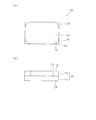
- thermosetting sealing sheet seat for thermosetting sealing with a separator which concerns on 1st Embodiment of this invention
- (b) is the front view.
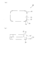
- (A) is a plane schematic diagram of the thermosetting sealing sheet with a separator concerning a 2nd embodiment of the present invention, and (b) is the front view.
- (A) is a plane schematic diagram of the thermosetting sealing sheet with a separator concerning a 3rd embodiment of the present invention, and (b) is the front view.
- FIG.1 (a) is a plane schematic diagram of the sheet
- FIG.1 (b) is the front view.
- the separator-attached thermosetting sealing sheet 10 has a configuration in which a thermosetting sealing sheet 16 is laminated on a separator 12.
- the thermosetting sealing sheet 16 has a rectangular shape in plan view, and rounds are formed at the four corners 18.
- the radius of curvature R1 of the radius formed at the corner portion 18 is in the range of 0.5 to 10 mm, preferably 1 to 5 mm. Since the radius of curvature R1 of the corner 18 is 0.5 mm or more, even if the corner 18 collides at the time of conveyance or the like, it receives a shock along the curved surface of the corner 18 so as to cause a large impact locally. Can be avoided. As a result, it is possible to prevent the sheet from being cracked or chipped. Moreover, since the curvature radius R1 is 10 mm or less, an area usable for sealing can be secured. Note that “R” refers to a rounded corner.
- the thermosetting sealing sheet 16 may have a tensile storage elastic modulus at 23 ° C. before thermosetting of 1 GPa to 20 GPa or 3 GPa to 5 GPa.
- the thermosetting sealing sheet 16 when the tensile storage modulus at 23 ° C. before thermosetting is 1 GPa or more, it is difficult to absorb the impact when an impact is applied.
- the thermosetting sealing sheet 16 according to this embodiment has rounded corners 18 and the radius of curvature R1 of these rounds is in the range of 0.5 to 10 mm. Even when the tensile storage modulus at 23 ° C. is relatively hard at 1 GPa or more, it is possible to avoid receiving a large impact locally by receiving an impact along the curved surface of the corner 18. As a result, it is possible to further prevent the sheet from being cracked or chipped.
- the said tensile storage elastic modulus is 5 GPa or less, adhesiveness with a separator is securable.
- the separator 12 has the same shape as the thermosetting sealing sheet 16 in plan view. Specifically, the separator 12 has a rectangular shape in plan view, and rounds are formed at the four corners 14.
- the radius of curvature R2 formed at the corner 14 is the same as the radius of curvature R1 formed at the corner 18 of the thermosetting sealing sheet 16. Since the separator 12 and the thermosetting sealing sheet 16 have the same shape in plan view, the curved surface of the corner portion 18 of the thermosetting sealing sheet 16 even if it collides during transportation or the like.
- by receiving an impact along the curved surface of the corner portion 14 of the separator 12 it is possible to further avoid receiving a large impact locally. As a result, it is possible to further prevent the sheet from being cracked or chipped.
- thermosetting sealing sheet 16 preferably contains an epoxy resin and a phenol resin. Thereby, favorable thermosetting is obtained.
- the epoxy resin is not particularly limited.
- triphenylmethane type epoxy resin, cresol novolac type epoxy resin, biphenyl type epoxy resin, modified bisphenol A type epoxy resin, bisphenol A type epoxy resin, bisphenol F type epoxy resin, modified bisphenol F type epoxy resin, dicyclopentadiene type Various epoxy resins such as an epoxy resin, a phenol novolac type epoxy resin, and a phenoxy resin can be used. These epoxy resins may be used alone or in combination of two or more.
- the epoxy equivalent is 150 to 250 and the softening point or the melting point is 50 to 130 ° C., solid at room temperature. From the viewpoint, triphenylmethane type epoxy resin, cresol novolac type epoxy resin, and biphenyl type epoxy resin are more preferable.
- the phenol resin is not particularly limited as long as it causes a curing reaction with the epoxy resin.
- a phenol novolac resin, a phenol aralkyl resin, a biphenyl aralkyl resin, a dicyclopentadiene type phenol resin, a cresol novolak resin, a resole resin, or the like is used.
- These phenolic resins may be used alone or in combination of two or more.
- phenolic resin those having a hydroxyl equivalent weight of 70 to 250 and a softening point of 50 to 110 ° C. are preferably used from the viewpoint of reactivity with the epoxy resin, and in particular, phenol novolak from the viewpoint of high curing reactivity. Resin can be used suitably. From the viewpoint of reliability, low hygroscopic materials such as phenol aralkyl resins and biphenyl aralkyl resins can also be suitably used.
- the blending ratio of the epoxy resin and the phenol resin is blended so that the total of hydroxyl groups in the phenol resin is 0.7 to 1.5 equivalents with respect to 1 equivalent of the epoxy group in the epoxy resin from the viewpoint of curing reactivity. It is preferable to use 0.9 to 1.2 equivalents.
- the total content of the epoxy resin and the phenol resin in the thermosetting sealing sheet 16 is preferably 2.0% by weight or more, and more preferably 3.0% by weight or more. Adhesive force is favorably obtained as it is 2.0% by weight or more.
- the total content of the epoxy resin and the phenol resin in the thermosetting sealing sheet 16 is preferably 20% by weight or less, and more preferably 10% by weight or less. If it is 20% by weight or less, the hygroscopicity can be lowered.
- the thermosetting sealing sheet 16 preferably contains a thermoplastic resin. Thereby, the handleability at the time of non-hardening and the low stress property of hardened
- Thermoplastic resins include natural rubber, butyl rubber, isoprene rubber, chloroprene rubber, ethylene-vinyl acetate copolymer, ethylene-acrylic acid copolymer, ethylene-acrylic acid ester copolymer, polybutadiene resin, polycarbonate resin, thermoplasticity.
- Polyimide resin, polyamide resin such as 6-nylon and 6,6-nylon, phenoxy resin, acrylic resin, saturated polyester resin such as PET and PBT, polyamideimide resin, fluororesin, styrene-isobutylene-styrene block copolymer Can be mentioned.
- These thermoplastic resins can be used alone or in combination of two or more. Of these, a styrene-isobutylene-styrene block copolymer is preferred from the viewpoint of low stress and low water absorption.
- the content of the thermoplastic resin in the thermosetting sealing sheet 16 is preferably 1.0% by weight or more, and more preferably 1.5% by weight or more.
- flexibility and flexibility are acquired as it is 1.0 weight% or more.
- the content of the thermoplastic resin in the thermosetting sealing sheet 16 is preferably 3.5% by weight or less, and more preferably 3% by weight or less. Adhesiveness with an electronic device or a board
- substrate can be improved as it is 3.5 weight% or less.
- thermosetting sealing sheet 16 preferably contains an inorganic filler.
- the inorganic filler is not particularly limited, and various conventionally known fillers can be used.
- quartz glass, talc, silica such as fused silica and crystalline silica
- alumina aluminum nitride, silicon nitride And boron nitride powder.
- silica and alumina are preferable, and silica is more preferable because the linear expansion coefficient can be satisfactorily reduced.
- silica powder is preferable, and fused silica powder is more preferable.
- fused silica powder examples include spherical fused silica powder and crushed fused silica powder. From the viewpoint of fluidity, spherical fused silica powder is preferable. Among these, those having an average particle diameter in the range of 10 to 30 ⁇ m are preferable, and those having a mean particle diameter in the range of 15 to 25 ⁇ m are more preferable.
- the average particle diameter can be derived, for example, by using a sample arbitrarily extracted from the population and measuring it using a laser diffraction / scattering particle size distribution measuring apparatus.
- the content of the inorganic filler in the thermosetting sealing sheet 16 is preferably 70% by volume or more, more preferably 74% by volume or more with respect to the entire thermosetting sealing sheet 16.
- a linear expansion coefficient can be designed low as it is 70 product% or more.
- the content of the inorganic filler is preferably 90% by volume or less, more preferably 85% by volume or less.
- liquidity, and adhesiveness are favorably obtained as it is 90 volume% or less.
- the content of the inorganic filler can be explained by using “wt%” as a unit. Typically, the content of silica will be described in units of “% by weight”. Since silica usually has a specific gravity of 2.2 g / cm 3 , the preferred range of the silica content (% by weight) is as follows. That is, the content of silica in the thermosetting sealing sheet 16 is preferably 81% by weight or more, and more preferably 84% by weight or more. The content of silica in the thermosetting sealing sheet 16 is preferably 94% by weight or less, and more preferably 91% by weight or less.
- the preferred range of the alumina content is as follows. That is, the content of alumina in the thermosetting sealing sheet 16 is preferably 88% by weight or more, and more preferably 90% by weight or more. The content of alumina in the thermosetting sealing sheet 16 is preferably 97% by weight or less, and more preferably 95% by weight or less.
- thermosetting sealing sheet 16 preferably contains a curing accelerator.
- the curing accelerator is not particularly limited as long as it can cure the epoxy resin and the phenol resin, and examples thereof include organophosphorus compounds such as triphenylphosphine and tetraphenylphosphonium tetraphenylborate; 2-phenyl-4, And imidazole compounds such as 5-dihydroxymethylimidazole and 2-phenyl-4-methyl-5-hydroxymethylimidazole.
- organophosphorus compounds such as triphenylphosphine and tetraphenylphosphonium tetraphenylborate
- 2-phenyl-4, And imidazole compounds such as 5-dihydroxymethylimidazole and 2-phenyl-4-methyl-5-hydroxymethylimidazole.
- the content of the curing accelerator is preferably 0.1 to 5 parts by weight with respect to 100 parts by weight of the total of the epoxy resin and the phenol resin.
- the thermosetting sealing sheet 16 preferably contains a flame retardant component. This can reduce the expansion of combustion when ignition occurs due to component short-circuiting or heat generation.
- a flame retardant component for example, various metal hydroxides such as aluminum hydroxide, magnesium hydroxide, iron hydroxide, calcium hydroxide, tin hydroxide, complex metal hydroxides; phosphazene flame retardants, etc. should be used. Can do.
- the content of the phosphorus element contained in the phosphazene flame retardant is preferably 12% by weight or more.
- the content of the flame retardant component in the thermosetting sealing sheet 16 is preferably 10% by weight or more, and more preferably 15% by weight or more in the total organic components excluding the filler. A flame retardance is favorably acquired as it is 10 weight% or more.
- the content of the thermoplastic resin in the thermosetting sealing sheet 16 is preferably 30% by weight or less, and more preferably 25% by weight or less. When the content is 30% by weight or less, there is a tendency that there is little decrease in physical properties of the cured product (specifically, physical properties such as glass transition temperature and high-temperature resin strength).
- the thermosetting sealing sheet 16 preferably contains a silane coupling agent.
- the silane coupling agent is not particularly limited, and examples thereof include 3-glycidoxypropyltrimethoxysilane.
- the content of the silane coupling agent in the thermosetting sealing sheet 16 is preferably 0.1 to 3% by weight. When the content is 0.1% by weight or more, sufficient strength of the cured product can be obtained and the water absorption rate can be lowered. Outgassing can be reduced as it is 3 weight% or less.
- the thermosetting sealing sheet 16 preferably contains a pigment.
- the pigment is not particularly limited, and examples thereof include carbon black.
- the pigment content in the thermosetting sealing sheet 16 is preferably 0.1 to 2% by weight.
- the content is 0.1% by weight or more, good marking properties can be obtained when marking is performed by laser marking or the like.
- the content is 2% by weight or less, a cured product strength is sufficiently obtained.
- thermosetting sealing sheet 16 may have a single layer structure or a multilayer structure in which two or more thermosetting sealing sheets are laminated.
- the thickness of the thermosetting sealing sheet 16 is not particularly limited, but is, for example, 50 ⁇ m to 2000 ⁇ m from the viewpoint of use as a sealing sheet.
- the manufacturing method of the thermosetting sealing sheet 16 is not particularly limited, and a kneaded product of the resin composition for forming the thermosetting sealing sheet 16 is prepared, and the obtained kneaded product is plasticized into a sheet shape.
- a method of processing a method in which a resin composition for forming the thermosetting sealing sheet 16 dissolved or dispersed in a solvent (varnish) is applied on the separator 12 and then dried, the (varnish) Examples include a method of coating the release treatment sheet, drying the coating film to form the thermosetting sealing sheet 16, and then transferring the thermosetting sealing sheet 16 onto the separator 12. .
- the thermosetting sealing sheet 16 is a SAW (Surface Acoustic Wave) filter; a MEMS (Micro Electro Mechanical Systems) such as a pressure sensor or a vibration sensor; an IC such as an LSI; a semiconductor such as a transistor; an electronic device such as a resistor; Can be used for sealing.
- SAW Surface Acoustic Wave
- MEMS Micro Electro Mechanical Systems
- a pressure sensor or a vibration sensor such as a pressure sensor or a vibration sensor
- an IC such as an LSI
- a semiconductor such as a transistor
- an electronic device such as a resistor
- thermosetting sealing sheet 16 It does not specifically limit as a sealing method, It can seal by a conventionally well-known method. For example, a method of laminating (mounting) an uncured thermosetting sealing sheet 16 on a substrate so as to cover an electronic device on the substrate, and then curing the thermosetting sealing sheet 16 for sealing. Etc. It does not specifically limit as a board
- substrate For example, a printed wiring board, a ceramic substrate, a silicon substrate, a metal substrate etc. are mentioned.
- the method for laminating the thermosetting sealing sheet 16 on the substrate is not particularly limited, and can be performed by a known method such as hot pressing or laminator.
- the temperature is, for example, 40 to 100 ° C., preferably 50 to 90 ° C.
- the pressure is, for example, 0.1 to 10 MPa, preferably 0.5 to 8 MPa
- the time is, for example, 0.3 to 10 minutes, preferably 0.5 to 5 minutes.
- separator 12 examples include plastic base materials such as plastic sheets; rubber base materials such as rubber sheets; foam base materials such as foam sheets; metal base materials such as metal foils and metal plates; A fiber-based substrate such as felt or net; a paper-based substrate such as paper; a laminate of the above-described substrates can be used. Especially, a plastic-type base material can be used suitably.
- plastic material examples include olefin resins such as polyethylene (PE), polypropylene (PP), and ethylene-propylene copolymer; ethylene-vinyl acetate copolymer (EVA), ionomer resin, ethylene- Copolymers containing ethylene as a monomer component such as (meth) acrylic acid copolymers and ethylene- (meth) acrylic acid ester (random, alternating) copolymers; polyethylene terephthalate (PET), polyethylene naphthalate (PEN), Polyester such as polybutylene terephthalate (PBT); Acrylic resin; Polyvinyl chloride (PVC); Polyurethane; Polycarbonate; Polyphenylene sulfide (PPS); Amide resin such as polyamide (nylon) and wholly aromatic polyamide (aramid); Ether ether ketone (PEEK); polyimides; polyetherimides; polyvinylidene chloride; ABS (acrylonitrile - butadiene -
- the separator 12 has a surface on which the thermosetting sealing sheet 16 is laminated.
- release agent used for the release treatment examples include a fluorine release agent, a long-chain alkyl acrylate release agent, and a silicone release agent. Of these, silicone release agents are preferred.
- the thickness of the separator 12 is not particularly limited, but is preferably 3 to 300 ⁇ m, more preferably 5 to 200 ⁇ m, and still more preferably 10 to 100 ⁇ m.
- the thickness of the separator 42 is preferably 3 to 300 ⁇ m, more preferably 5 to 200 ⁇ m, and still more preferably 10 to 100 ⁇ m.
- FIG.2 (a) is a plane schematic diagram of the sheet
- FIG.2 (b) is the front view.
- the thermosetting sealing sheet with a separator according to the second embodiment is different from the thermosetting sealing sheet with a separator 10 according to the first embodiment in the shape of the separator. Common with the sheet 10. Therefore, in the following, the description will focus on parts that are different from the thermosetting sealing sheet 10 with a separator. Moreover, suppose that the same code
- thermosetting sealing sheet 20 with a separator has a configuration in which a thermosetting sealing sheet 16 is laminated on a separator 22. Since the thermosetting sealing sheet 16 is the same as that of the first embodiment, the description thereof is omitted.
- the separator 22 is rectangular in plan view, and no corners are formed at the corners 24. Each side of the separator 22 is flush with each side of the thermosetting sealing sheet 16 in plan view. While the corners 24 of the separator 22 are not rounded, the corners 18 of the thermosetting sealing sheet 16 are rounded.
- seat 16 for conductive sealing is not formed exists. Since there is a region 25 where the thermosetting sealing sheet 16 is not formed on the corner 24 of the separator 22, even if it collides from the corner 18 side during transportation or the like, Take the shock. Therefore, the impact on the thermosetting sealing sheet 16 can be reduced.
- the radius of curvature R1 formed at the corner 18 of the thermosetting sealing sheet 16 is within the range of 0.5 to 10 mm.
- an alignment hole may be formed in the corner 24 of the separator 22 or an alignment mark may be formed by printing or the like. This makes it possible to perform more accurate alignment.
- the same material as the separator 12 can be used.
- FIG.3 (a) is a plane schematic diagram of the sheet
- FIG.3 (b) is the front view.
- the thermosetting sealing sheet with a separator according to the third embodiment is different from the thermosetting sealing sheet with a separator 10 according to the first embodiment in the shape of the separator. Common with the sheet 10. Therefore, in the following, the description will focus on parts that are different from the thermosetting sealing sheet 10 with a separator. Moreover, suppose that the same code
- thermosetting sealing sheet 30 with a separator has a configuration in which a thermosetting sealing sheet 16 is laminated on a separator 32. Since the thermosetting sealing sheet 16 is the same as that of the first embodiment, the description thereof is omitted.
- the separator 32 has a rectangular shape in plan view, and rounds are formed at the four corners 34.
- the radius of curvature R2 formed at the corner 34 is not particularly limited as long as it is smaller than the radius of curvature R1 of the radius formed at the corner 18 of the thermosetting sealing sheet 16. It can be selected from a range of up to 10 mm.
- Each side of the separator 32 is flush with each side of the thermosetting sealing sheet 16 in plan view. Since the radius of curvature R2 formed in the corner 34 of the separator 32 is smaller than the radius of curvature R1 formed in the corner 18 of the thermosetting sealing sheet 16, the corner of the separator 32 is provided. An area 35 where the thermosetting sealing sheet 16 is not formed is present on 34.
- thermosetting sealing sheet 16 Since there is a region 35 where the thermosetting sealing sheet 16 is not formed on the corner 34 of the separator 32, even if it collides from the corner 18 side during transportation or the like, first, only by the separator 32. Take the shock. Therefore, the impact on the thermosetting sealing sheet 16 can be reduced. At this time, since corners 34 of the separator 32 are rounded, by receiving an impact along the curved surface of the corner 34 of the separator 32, it is possible to avoid receiving a large impact locally.
- the radius of curvature R1 formed at the corner 18 of the thermosetting sealing sheet 16 is in the range of 0.5 to 10 mm, so that the thermosetting By receiving an impact along the curved surface of the corner portion 18 of the sealing sheet 16, it is possible to avoid receiving a large impact locally. As a result, it is possible to prevent the sheet from being cracked or chipped. Moreover, since the area
- an alignment hole may be formed in the corner 34 of the separator 32, or an alignment mark may be formed by printing or the like. This makes it possible to perform more accurate alignment.
- the same material as the separator 12 can be used.
- thermosetting sealing sheet has a rectangular shape
- shape of the thermosetting sealing sheet of the present invention has rounded corners. If it is, it will not be limited to this example, For example, polygonal shape (for example, hexagonal shape) may be sufficient.
- the shape of the separator is not limited to this example, and may be set according to the shape of the thermosetting sealing sheet.
- it may be polygonal (for example, hexagonal).
- the corners of the thermosetting sealing sheet are preferably all rounded, but the present invention is not limited to this example. It is sufficient that a radius is formed in at least one corner of the sheet for sealing property. It is because it can avoid receiving a big impact locally in the location where the said round is formed, and can suppress that a crack and a chip
- the rounds are formed at the corners of the separator as in the first embodiment and the third embodiment described above, the rounds are preferably formed at all the corners. It suffices if a radius is formed in at least one corner of the separator. It is because it can avoid receiving a big impact locally in the location where the said round is formed, and can suppress that a crack and a chip
- the present invention is not limited to the above-described example, and it is possible to make design changes as appropriate within a range that satisfies the configuration of the present invention.
- Epoxy resin YSLV-80XY manufactured by Nippon Steel Chemical Co., Ltd. (bisphenol F type epoxy resin, epkin equivalent 200 g / eq. Softening point 80 ° C.)
- Phenol resin MEH-7785-SS (Maywa Kasei Co., Ltd.) (phenolic resin having a biphenylaralkyl skeleton, hydroxyl group equivalent 203 g / eq., Softening point 67 ° C.)
- Thermoplastic resin SIBSTER 072T (styrene-isobutylene-styrene block copolymer) manufactured by Kaneka Corporation
- Inorganic filler FB-9454FC manufactured by Denki Kagaku Kogyo Co., Ltd.
- Silane coupling agent KBM-403 (3-glycidoxypropyltrimethoxysilane) manufactured by Shin-Etsu Chemical Co., Ltd.
- Carbon black # 20 manufactured by Mitsubishi Chemical Flame retardant: FP-100 manufactured by Fushimi
- phosphazene flame retardant compound represented by formula (4)
- Curing accelerator 2PHZ-PW (2-phenyl-4,5-dihydroxymethylimidazole) manufactured by Shikoku Kasei Kogyo Co., Ltd.
- thermosetting sealing sheet with separator Examples 1 to 3, Comparative Example 1
- Each component was blended according to the blending ratio shown in Table 1, and melt-kneaded under a reduced pressure condition (0.01 kg / cm 2 ) at 60 to 120 ° C. for 10 minutes using a biaxial kneader to prepare a kneaded product.
- the obtained kneaded material was formed into a sheet shape by a flat plate pressing method to produce a thermosetting sealing sheet having a size of 100 mm ⁇ 100 mm ⁇ thickness 0.5 mm (no corners are rounded).
- the separator was affixed on the obtained thermosetting sealing sheet.
- Example 1 As the separator, product name: MRF-50 (100 mm ⁇ 100 mm ⁇ thickness 0.05 mm (there is no corner at the corner)) manufactured by Mitsubishi Chemical Corporation was used.
- a round having a radius of curvature of 1 mm was formed at the corner of the sealing sheet using a Thomson mold. Note that punching with a Thomson die is performed only on the sealing sheet, and the separator is not punched.
- Example 2 the sealing sheet and the separator were simultaneously punched out using a Thomson die, and a radius with a radius of curvature of 3 mm was formed at the corner of the sealing sheet and the corner of the separator.
- Example 3 first, a round having a radius of curvature of 5 mm was formed at the corner of the sealing sheet using a Thomson mold. Next, a round having a radius of curvature of 1 mm was formed at the corner of the separator using another Thomson mold. When the sealing sheet is punched, only the sealing sheet is used, and the separator is not punched. For Comparative Example 1, no punching was performed.
- MEK methyl ethyl ketone
- the separator was affixed on the obtained thermosetting sealing sheet.
- a round having a radius of curvature of 1 mm was formed at the corner of the sealing sheet using a Thomson mold. Note that punching with a Thomson die is performed only on the sealing sheet, and the separator is not punched.
- thermosetting sealing sheet ⁇ Measurement of tensile storage elastic modulus at 23 ° C. before thermosetting of thermosetting sealing sheet>
- the separator was peeled off from the produced thermosetting sealing sheet with a separator.
- the tensile storage elastic modulus at 23 ° C. before thermosetting of the thermosetting sealing sheet was measured using a viscoelasticity measuring apparatus (Rheometrics: model: RSA-II). More specifically, the sample size is 30.0 ⁇ length 5.0 ⁇ thickness 0.1 mm, the measurement sample is set in a film tension measurement jig, and the frequency is in the temperature range of ⁇ 30 ° C. to 250 ° C. The measurement was performed under the conditions of 1.0 Hz, a strain of 0.025%, and a heating rate of 10 ° C./min. As a result, the storage elastic modulus at 23 was 3.0 GPa.
- thermosetting sealing 10
- separator 12 22
- Separator 14 24
- Corner 16 of separator 16 Sheet for thermosetting sealing 18 Corner 25 of sheet for thermosetting sealing, 35 Region where thermosetting sealing sheet is not formed
Landscapes
- Laminated Bodies (AREA)
- Sealing Material Composition (AREA)
- Adhesive Tapes (AREA)
- Adhesives Or Adhesive Processes (AREA)
- Structures Or Materials For Encapsulating Or Coating Semiconductor Devices Or Solid State Devices (AREA)
Abstract
隅部にアールが形成されており、アールの曲率半径R1が0.5~10mmの範囲内である熱硬化性封止用シート。
Description
本発明は、熱硬化性封止用シート、及び、セパレータ付き熱硬化性封止用シートに関する。
電子デバイスパッケージの作製には、代表的に、基板などに固定された1又は複数の電子デバイスを封止樹脂にて封止し、必要に応じて封止体を電子デバイス単位のパッケージとなるようにダイシングするという手順が採用されている。このような封止樹脂として、熱硬化性樹脂シートが用いられていることがある(例えば、特許文献1参照)。
しかしながら、上述した従来の熱硬化性樹脂シートは、平面視で矩形状のシートとして搬送される場合、隅部が衝突し、シートに割れや欠けが発生するおそれがあるといった問題があった。特に、熱硬化性樹脂シートは、電子デバイスパッケージの製造工程において熱硬化を進行させないように低温(例えば、-20~60℃)に維持して搬送が行なわれる場合がある。しかしながら、低温時には、熱硬化性樹脂シートは、硬い状態であるため、衝撃が加えられるとその衝撃を吸収しにくく割れや欠けが発生しやすいといった問題があった。また、製品として出荷された熱硬化性樹脂シートが顧客先まで輸送される際にも、隅部が衝突し、シートに割れや欠けが発生するおそれがあるといった問題があった。
本発明は上述した課題に鑑みてなされたものであり、その目的は、輸送、搬送時等に隅部が衝突し、シートに割れや欠けが発生することを抑制することが可能な熱硬化性封止用シート、及び、セパレータ付き熱硬化性封止用シートを提供することにある。
本願発明者等は、下記の構成を採用することにより、前記の課題を解決できることを見出して本発明を完成させるに至った。
すなわち、本発明は、熱硬化性封止用シートであって、
隅部にアールが形成されており、前記アールの曲率半径R1が0.5~10mmの範囲内であることを特徴とする。
隅部にアールが形成されており、前記アールの曲率半径R1が0.5~10mmの範囲内であることを特徴とする。
本発明に係る熱硬化性封止用シートによれば、隅部にアールが形成されており、前記アールの曲率半径R1が0.5mm以上であるため、搬送時等に隅部が衝突したとしても、隅部の曲面に沿って衝撃を受けることにより、局所的に大きな衝撃を受けることを回避できる。その結果、シートに割れや欠けが発生することを抑制することができる。また、前記曲率半径R1が10mm以下であるため、封止に使用可能なエリアを確保できる。
また、本発明に係るセパレータ付き熱硬化性封止用シートは、前記に記載の熱硬化性封止用シートが、セパレータ上に積層されており、
前記セパレータの隅部上には、前記熱硬化性封止用シートが形成されていない領域が存在することを特徴とする。
前記セパレータの隅部上には、前記熱硬化性封止用シートが形成されていない領域が存在することを特徴とする。
前記構成によれば、セパレータの隅部上には、熱硬化性封止用シートが形成されていない領域が存在するため、搬送時等に隅部側から衝突したとしても、まず、セパレータのみにより衝撃を受け止める。従って、熱硬化性封止用シートへの衝撃を緩和することができる。
また、セパレータで衝撃を吸収しきれなくても、熱硬化性封止用シートの隅部に形成されたアールの曲率半径R1が0.5~10mmの範囲内であるため、熱硬化性封止用シートの隅部の曲面に沿って衝撃を受けることにより、局所的に大きな衝撃を受けることを回避できる。その結果、シートに割れや欠けが発生することを抑制することができる。
また、セパレータの隅部上には、熱硬化性封止用シートが形成されていない領域が設けられているため、セパレータを容易に熱硬化性封止用シートから剥離することができる。
また、セパレータで衝撃を吸収しきれなくても、熱硬化性封止用シートの隅部に形成されたアールの曲率半径R1が0.5~10mmの範囲内であるため、熱硬化性封止用シートの隅部の曲面に沿って衝撃を受けることにより、局所的に大きな衝撃を受けることを回避できる。その結果、シートに割れや欠けが発生することを抑制することができる。
また、セパレータの隅部上には、熱硬化性封止用シートが形成されていない領域が設けられているため、セパレータを容易に熱硬化性封止用シートから剥離することができる。
また、本発明に係るセパレータ付き熱硬化性封止用シートは、前記に記載の熱硬化性封止用シートが、セパレータ上に積層されており、
前記セパレータと前記熱硬化性封止用シートとが、平面視で同一の形状を有していることを特徴とする。
前記セパレータと前記熱硬化性封止用シートとが、平面視で同一の形状を有していることを特徴とする。
前記構成によれば、セパレータと前記熱硬化性封止用シートとが、平面視で同一の形状を有しているため、前記セパレータの隅部の曲率半径は、前記熱硬化性封止用シートの隅部の曲率半径R1と同一となる。従って、搬送時等に衝突したとしても、熱硬化性封止用シートの隅部の曲面だけでなく、セパレータの隅部の曲面に沿って衝撃を受けることにより、局所的に大きな衝撃を受けることをより回避できる。その結果、シートに割れや欠けが発生することをより抑制することができる。
前記熱硬化性封止用シートにおいては、熱硬化前における23℃での引張貯蔵弾性率が、1GPa~5GPaであってもよい。
また、前記セパレータ付き熱硬化性封止用シートにおいては、前記熱硬化性封止用シートの熱硬化前における23℃での引張貯蔵弾性率が、1GPa~5GPaであってもよい。
また、前記セパレータ付き熱硬化性封止用シートにおいては、前記熱硬化性封止用シートの熱硬化前における23℃での引張貯蔵弾性率が、1GPa~5GPaであってもよい。
熱硬化前における23℃での引張貯蔵弾性率が、1GPa以上である熱硬化性封止用シートは、比較的硬く、衝撃が加えられるとその衝撃を吸収しにくい。しかしながら、本発明の熱硬化性封止用シートは、隅部の曲率半径R1が0.5~10mmの範囲内であるため、熱硬化前における23℃での引張貯蔵弾性率が、1GPa以上と比較的硬いものであっても、隅部の曲面に沿って衝撃を受けることにより、局所的に大きな衝撃を受けることを回避できる。その結果、シートに割れや欠けが発生することをさらに抑制することができる。また、前記引張貯蔵弾性率が、5GPa以下であるため、セパレータとの密着性を維持できる。
本発明によれば、搬送時等に隅部が衝突し、シートに割れや欠けが発生することを抑制することが可能な熱硬化性封止用シート、及び、セパレータ付き熱硬化性封止用シートを提供することができる。
以下、本発明の実施形態について、図面を参照しつつ説明する。ただし、本発明はこれらの実施形態のみに限定されるものではない。
[第1実施形態]
図1(a)は、本発明の第1実施形態に係るセパレータ付き熱硬化性封止用シートの平面模式図であり、図1(b)は、その正面図である。セパレータ付き熱硬化性封止用シート10は、セパレータ12上に熱硬化性封止用シート16が積層された構成を有する。
図1(a)は、本発明の第1実施形態に係るセパレータ付き熱硬化性封止用シートの平面模式図であり、図1(b)は、その正面図である。セパレータ付き熱硬化性封止用シート10は、セパレータ12上に熱硬化性封止用シート16が積層された構成を有する。
熱硬化性封止用シート16は、平面視で矩形状の形状を有しており、4つの隅部18にアールが形成されている。隅部18に形成されているアールの曲率半径R1は、0.5~10mmの範囲内であり、好ましくは、1~5mmである。隅部18のアールの曲率半径R1が0.5mm以上であるため、搬送時等に隅部18が衝突したとしても、隅部18の曲面に沿って衝撃を受けることにより、局所的に大きな衝撃を受けることを回避できる。その結果、シートに割れや欠けが発生することを抑制することができる。また、前記曲率半径R1が10mm以下であるため、封止に使用可能なエリアを確保できる。なお、アールとは、角を丸めて円弧状にしたものをいう。
熱硬化性封止用シート16は、熱硬化前における23℃での引張貯蔵弾性率が、1GPa~20GPaであってもよく、3GPa~5GPaであってもよい。熱硬化性封止用シートにおいて、熱硬化前における23℃での引張貯蔵弾性率が1GPa以上である場合、衝撃が加えられるとその衝撃を吸収しにくい。しかしながら、本実施形態に係る熱硬化性封止用シート16は、隅部18にアールが形成されており、このアールの曲率半径R1が0.5~10mmの範囲内であるため、熱硬化前における23℃での引張貯蔵弾性率が、1GPa以上と比較的硬いものであっても、隅部18の曲面に沿って衝撃を受けることにより、局所的に大きな衝撃を受けることを回避できる。その結果、シートに割れや欠けが発生することをさらに抑制することができる。また、前記引張貯蔵弾性率が、5GPa以下であるため、セパレータとの密着性を確保できる。
セパレータ12は、平面視で熱硬化性封止用シート16と同一の形状を有している。具体的に、セパレータ12は、平面視で矩形状の形状を有しており、4つの隅部14にアールが形成されている。隅部14に形成されているアールの曲率半径R2は、熱硬化性封止用シート16の隅部18に形成されているアールの曲率半径R1と同一である。セパレータ12と熱硬化性封止用シート16とが、平面視で同一の形状を有しているため、搬送時等に衝突したとしても、熱硬化性封止用シート16の隅部18の曲面だけでなく、セパレータ12の隅部14の曲面に沿って衝撃を受けることにより、局所的に大きな衝撃を受けることをより回避できる。その結果、シートに割れや欠けが発生することをより抑制することができる。
(熱硬化性封止用シート)
熱硬化性封止用シート16はエポキシ樹脂、及びフェノール樹脂を含むことが好ましい。これにより、良好な熱硬化性が得られる。
熱硬化性封止用シート16はエポキシ樹脂、及びフェノール樹脂を含むことが好ましい。これにより、良好な熱硬化性が得られる。
エポキシ樹脂としては、特に限定されるものではない。例えば、トリフェニルメタン型エポキシ樹脂、クレゾールノボラック型エポキシ樹脂、ビフェニル型エポキシ樹脂、変性ビスフェノールA型エポキシ樹脂、ビスフェノールA型エポキシ樹脂、ビスフェノールF型エポキシ樹脂、変性ビスフェノールF型エポキシ樹脂、ジシクロペンタジエン型エポキシ樹脂、フェノールノボラック型エポキシ樹脂、フェノキシ樹脂などの各種のエポキシ樹脂を用いることができる。これらエポキシ樹脂は単独で用いてもよいし2種以上併用してもよい。
エポキシ樹脂の硬化後の靭性及びエポキシ樹脂の反応性を確保する観点からは、エポキシ当量150~250、軟化点もしくは融点が50~130℃の常温で固形のものが好ましく、なかでも、信頼性の観点から、トリフェニルメタン型エポキシ樹脂、クレゾールノボラック型エポキシ樹脂、ビフェニル型エポキシ樹脂がより好ましい。
フェノール樹脂は、エポキシ樹脂との間で硬化反応を生起するものであれば特に限定されるものではない。例えば、フェノールノボラック樹脂、フェノールアラルキル樹脂、ビフェニルアラルキル樹脂、ジシクロペンタジエン型フェノール樹脂、クレゾールノボラック樹脂、レゾール樹脂などが用いられる。これらフェノール樹脂は単独で用いてもよいし、2種以上併用してもよい。
フェノール樹脂としては、エポキシ樹脂との反応性の観点から、水酸基当量が70~250、軟化点が50~110℃のものを用いることが好ましく、なかでも硬化反応性が高いという観点から、フェノールノボラック樹脂を好適に用いることができる。また、信頼性の観点から、フェノールアラルキル樹脂やビフェニルアラルキル樹脂のような低吸湿性のものも好適に用いることができる。
エポキシ樹脂とフェノール樹脂の配合割合は、硬化反応性という観点から、エポキシ樹脂中のエポキシ基1当量に対して、フェノール樹脂中の水酸基の合計が0.7~1.5当量となるように配合することが好ましく、より好ましくは0.9~1.2当量である。
熱硬化性封止用シート16中のエポキシ樹脂及びフェノール樹脂の合計含有量は、2.0重量%以上が好ましく、3.0重量%以上がより好ましい。2.0重量%以上であると、接着力が良好に得られる。熱硬化性封止用シート16中のエポキシ樹脂及びフェノール樹脂の合計含有量は、20重量%以下が好ましく、10重量%以下がより好ましい。20重量%以下であると、吸湿性を低くすることができる。
熱硬化性封止用シート16は、熱可塑性樹脂を含むことが好ましい。これにより、未硬化時のハンドリング性や、硬化物の低応力性が得られる。
熱可塑性樹脂としては、天然ゴム、ブチルゴム、イソプレンゴム、クロロプレンゴム、エチレン-酢酸ビニル共重合体、エチレン-アクリル酸共重合体、エチレン-アクリル酸エステル共重合体、ポリブタジエン樹脂、ポリカーボネート樹脂、熱可塑性ポリイミド樹脂、6-ナイロンや6,6-ナイロンなどのポリアミド樹脂、フェノキシ樹脂、アクリル樹脂、PETやPBTなどの飽和ポリエステル樹脂、ポリアミドイミド樹脂、フッ素樹脂、スチレン-イソブチレン-スチレンブロック共重合体などが挙げられる。これらの熱可塑性樹脂は単独で、又は2種以上を併用して用いることができる。なかでも、低応力性、低吸水性という観点から、スチレン-イソブチレン-スチレンブロック共重合体が好ましい。
熱硬化性封止用シート16中の熱可塑性樹脂の含有量は、1.0重量%以上が好ましく、1.5重量%以上がより好ましい。1.0重量%以上であると、柔軟性、可撓性が得られる。熱硬化性封止用シート16中の熱可塑性樹脂の含有量は、3.5重量%以下が好ましく、3重量%以下がより好ましい。3.5重量%以下であると、電子デバイスや基板との接着性を高められる。
熱硬化性封止用シート16は、無機質充填剤を含むことが好ましい。
無機質充填剤は、特に限定されるものではなく、従来公知の各種充填剤を用いることができ、例えば、石英ガラス、タルク、シリカ(溶融シリカや結晶性シリカなど)、アルミナ、窒化アルミニウム、窒化珪素、窒化ホウ素の粉末が挙げられる。これらは単独で用いてもよいし、2種以上併用してもよい。なかでも、線膨張係数を良好に低減できるという理由から、シリカ、アルミナが好ましく、シリカがより好ましい。
シリカとしては、シリカ粉末が好ましく、溶融シリカ粉末がより好ましい。溶融シリカ粉末としては、球状溶融シリカ粉末、破砕溶融シリカ粉末が挙げられるが、流動性という観点から、球状溶融シリカ粉末が好ましい。なかでも、平均粒径が10~30μmの範囲のものが好ましく、15~25μmの範囲のものがより好ましい。
なお、平均粒径は、例えば、母集団から任意に抽出される試料を用い、レーザー回折散乱式粒度分布測定装置を用いて測定することにより導き出すことができる。
なお、平均粒径は、例えば、母集団から任意に抽出される試料を用い、レーザー回折散乱式粒度分布測定装置を用いて測定することにより導き出すことができる。
熱硬化性封止用シート16中の無機質充填剤の含有量は、熱硬化性封止用シート16全体に対して、好ましくは70体積%以上であり、より好ましくは74体積%以上である。70積%以上であると、線膨張係数を低く設計できる。一方、無機質充填剤の含有量は、好ましくは90体積%以下であり、より好ましくは85体積%以下である。90体積%以下であると、柔軟性、流動性、接着性が良好に得られる。
無機質充填剤の含有量は、「重量%」を単位としても説明できる。代表的にシリカの含有量について、「重量%」を単位として説明する。
シリカは通常、比重2.2g/cm3であるので、シリカの含有量(重量%)の好適範囲は以下のとおりである。
すなわち、熱硬化性封止用シート16中のシリカの含有量は、81重量%以上が好ましく、84重量%以上がより好ましい。熱硬化性封止用シート16中のシリカの含有量は、94重量%以下が好ましく、91重量%以下がより好ましい。
シリカは通常、比重2.2g/cm3であるので、シリカの含有量(重量%)の好適範囲は以下のとおりである。
すなわち、熱硬化性封止用シート16中のシリカの含有量は、81重量%以上が好ましく、84重量%以上がより好ましい。熱硬化性封止用シート16中のシリカの含有量は、94重量%以下が好ましく、91重量%以下がより好ましい。
アルミナは通常、比重3.9g/cm3であるので、アルミナの含有量(重量%)の好適範囲は以下のとおりである。
すなわち、熱硬化性封止用シート16中のアルミナの含有量は、88重量%以上が好ましく、90重量%以上がより好ましい。熱硬化性封止用シート16中のアルミナの含有量は、97重量%以下が好ましく、95重量%以下がより好ましい。
すなわち、熱硬化性封止用シート16中のアルミナの含有量は、88重量%以上が好ましく、90重量%以上がより好ましい。熱硬化性封止用シート16中のアルミナの含有量は、97重量%以下が好ましく、95重量%以下がより好ましい。
熱硬化性封止用シート16は、硬化促進剤を含むことが好ましい。
硬化促進剤としては、エポキシ樹脂とフェノール樹脂の硬化を進行させるものであれば特に限定されず、例えば、トリフェニルホスフィン、テトラフェニルホスホニウムテトラフェニルボレートなどの有機リン系化合物;2-フェニル-4,5-ジヒドロキシメチルイミダゾール、2-フェニル-4-メチル-5-ヒドロキシメチルイミダゾールなどのイミダゾール系化合物;などが挙げられる。
硬化促進剤の含有量は、エポキシ樹脂及びフェノール樹脂の合計100重量部に対して0.1~5重量部が好ましい。
熱硬化性封止用シート16は、難燃剤成分を含むことが好ましい。これにより、部品ショートや発熱などにより発火した際の、燃焼拡大を低減できる。難燃剤組成分としては、例えば水酸化アルミニウム、水酸化マグネシウム、水酸化鉄、水酸化カルシウム、水酸化スズ、複合化金属水酸化物などの各種金属水酸化物;ホスファゼン系難燃剤などを用いることができる。
少量でも難燃効果を発揮するという観点から、ホスファゼン系難燃剤に含まれるリン元素の含有率は、12重量%以上であることが好ましい。
熱硬化性封止用シート16中の難燃剤成分の含有量は、フィラーを除いた全有機成分中、10重量%以上が好ましく、15重量%以上がより好ましい。10重量%以上であると、難燃性が良好に得られる。熱硬化性封止用シート16中の熱可塑性樹脂の含有量は、30重量%以下が好ましく、25重量%以下がより好ましい。30重量%以下であると、硬化物の物性低下(具体的には、ガラス転移温度や高温樹脂強度などの物性の低下)が少ない傾向がある。
熱硬化性封止用シート16は、シランカップリング剤を含むことが好ましい。シランカップリング剤としては特に限定されず、3-グリシドキシプロピルトリメトキシシランなどが挙げられる。
熱硬化性封止用シート16中のシランカップリング剤の含有量は、0.1~3重量%が好ましい。0.1重量%以上であると、硬化物の強度が十分得られ吸水率を低くできる。3重量%以下であると、アウトガスを低減できる。
熱硬化性封止用シート16は、顔料を含むことが好ましい。顔料としては特に限定されず、カーボンブラックなどが挙げられる。
熱硬化性封止用シート16中の顔料の含有量は、0.1~2重量%が好ましい。0.1重量%以上であると、レーザーマーキング等によるマーキングをした際の良好なマーキング性が得られる。2重量%以下であると、硬化物強度が十分得られる。
なお、樹脂組成物には、上記の各成分以外に必要に応じて、他の添加剤を適宜配合できる。
熱硬化性封止用シート16は、単層構造であってもよいし、2以上の熱硬化性封止用シートを積層した多層構造であってもよい。
熱硬化性封止用シート16の厚さは、特に限定されないが、封止用シートとして使用する観点から、例えば、50μm~2000μmである。
熱硬化性封止用シート16の製造方法は特に限定されず、熱硬化性封止用シート16を形成するための樹脂組成物の混練物を調製し、得られた混練物をシート状に塑性加工する方法、熱硬化性封止用シート16を形成するための樹脂組成物を溶剤に溶解又は分散させたもの(ワニス)をセパレータ12上に塗布し、その後乾燥させる方法、該(ワニス)を離型処理シート上に塗布し、塗布膜を乾燥させて熱硬化性封止用シート16を形成した上で、この熱硬化性封止用シート16をセパレータ12上に転写する方法などが挙げられる。
熱硬化性封止用シート16は、SAW(Surface Acoustic Wave)フィルタ;圧力センサ、振動センサなどのMEMS(Micro Electro Mechanical Systems);LSIなどのIC、トランジスタなどの半導体;コンデンサ;抵抗などの電子デバイスの封止に使用することができる。
封止方法としては特に限定されず、従来公知の方法で封止できる。例えば、基板上の電子デバイスを覆うように未硬化の熱硬化性封止用シート16を基板上に積層(載置)し、次いで熱硬化性封止用シート16を硬化させて封止する方法などが挙げられる。基板としては特に限定されず、例えば、プリント配線基板、セラミック基板、シリコン基板、金属基板などが挙げられる。
熱硬化性封止用シート16を基板上に積層する方法は特に限定されず、熱プレスやラミネータなど公知の方法により行うことができる。熱プレス条件としては、温度が、例えば、40~100℃、好ましくは50~90℃であり、圧力が、例えば、0.1~10MPa、好ましくは0.5~8MPaであり、時間が、例えば0.3~10分間、好ましくは0.5~5分間である。これにより、電子デバイスが熱硬化性封止用シート16に埋め込まれた電子デバイスパッケージを得ることができる。
(セパレータ)
セパレータ12としては、例えば、プラスチックシートなどのプラスチック系基材;ゴムシートなどのゴム系基材;発泡シートなどの発泡体基材;金属箔、金属板などの金属系基材;布、不織布、フェルト、ネットなどの繊維系基材;紙などの紙系基材;前記基材の積層体等を用いることができる。なかでも、プラスチック系基材を好適に用いることができる。このようなプラスチック材における素材としては、例えば、ポリエチレン(PE)、ポリプロピレン(PP)、エチレン-プロピレン共重合体等のオレフィン系樹脂;エチレン-酢酸ビニル共重合体(EVA)、アイオノマー樹脂、エチレン-(メタ)アクリル酸共重合体、エチレン-(メタ)アクリル酸エステル(ランダム、交互)共重合体等のエチレンをモノマー成分とする共重合体;ポリエチレンテレフタレート(PET)、ポリエチレンナフタレート(PEN)、ポリブチレンテレフタレート(PBT)等のポリエステル;アクリル系樹脂;ポリ塩化ビニル(PVC);ポリウレタン;ポリカーボネート;ポリフェニレンスルフィド(PPS);ポリアミド(ナイロン)、全芳香族ポリアミド(アラミド)等のアミド系樹脂;ポリエーテルエーテルケトン(PEEK);ポリイミド;ポリエーテルイミド;ポリ塩化ビニリデン;ABS(アクリロニトリル-ブタジエン-スチレン共重合体);セルロース系樹脂;シリコーン樹脂;フッ素樹脂などが挙げられる。なお、セパレータ12の製造方法としては、従来公知の方法により形成することができる。
セパレータ12としては、例えば、プラスチックシートなどのプラスチック系基材;ゴムシートなどのゴム系基材;発泡シートなどの発泡体基材;金属箔、金属板などの金属系基材;布、不織布、フェルト、ネットなどの繊維系基材;紙などの紙系基材;前記基材の積層体等を用いることができる。なかでも、プラスチック系基材を好適に用いることができる。このようなプラスチック材における素材としては、例えば、ポリエチレン(PE)、ポリプロピレン(PP)、エチレン-プロピレン共重合体等のオレフィン系樹脂;エチレン-酢酸ビニル共重合体(EVA)、アイオノマー樹脂、エチレン-(メタ)アクリル酸共重合体、エチレン-(メタ)アクリル酸エステル(ランダム、交互)共重合体等のエチレンをモノマー成分とする共重合体;ポリエチレンテレフタレート(PET)、ポリエチレンナフタレート(PEN)、ポリブチレンテレフタレート(PBT)等のポリエステル;アクリル系樹脂;ポリ塩化ビニル(PVC);ポリウレタン;ポリカーボネート;ポリフェニレンスルフィド(PPS);ポリアミド(ナイロン)、全芳香族ポリアミド(アラミド)等のアミド系樹脂;ポリエーテルエーテルケトン(PEEK);ポリイミド;ポリエーテルイミド;ポリ塩化ビニリデン;ABS(アクリロニトリル-ブタジエン-スチレン共重合体);セルロース系樹脂;シリコーン樹脂;フッ素樹脂などが挙げられる。なお、セパレータ12の製造方法としては、従来公知の方法により形成することができる。
セパレータ12は、熱硬化性封止用シート16が積層される面が剥離処理されていることが好ましい。
前記剥離処理に用いられる離型剤としては、フッ素系剥離剤、長鎖アルキルアクリレート系剥離剤、シリコーン系離型剤等を挙げることができる。なかでも、シリコーン系剥離剤が好ましい。
セパレータ12の厚さは、特に制限されないが、3~300μmが好ましく、5~200μmがより好ましく、10~100μmがさらに好ましい。セパレータ42の厚さを10μm以上とすることにより、衝撃を緩和しやすくなる。また、300μm以下とすることにより、剥離が容易となる。
以上、第1実施形態では、セパレータと熱硬化性封止用シートとが、平面視で同一の形状を有している場合について説明した。
[第2実施形態]
図2(a)は、本発明の第2実施形態に係るセパレータ付き熱硬化性封止用シートの平面模式図であり、図2(b)は、その正面図である。第2実施形態に係るセパレータ付き熱硬化性封止用シートは、セパレータの形状が第1実施形態に係るセパレータ付き熱硬化性封止用シート10と異なり、その他でセパレータ付き熱硬化性封止用シート10と共通する。そこで、以下では、セパレータ付き熱硬化性封止用シート10と異なる部分を中心に説明する。また、セパレータ付き熱硬化性封止用シート10と共通する部分については、同一の符号を付すこととする。
図2(a)は、本発明の第2実施形態に係るセパレータ付き熱硬化性封止用シートの平面模式図であり、図2(b)は、その正面図である。第2実施形態に係るセパレータ付き熱硬化性封止用シートは、セパレータの形状が第1実施形態に係るセパレータ付き熱硬化性封止用シート10と異なり、その他でセパレータ付き熱硬化性封止用シート10と共通する。そこで、以下では、セパレータ付き熱硬化性封止用シート10と異なる部分を中心に説明する。また、セパレータ付き熱硬化性封止用シート10と共通する部分については、同一の符号を付すこととする。
セパレータ付き熱硬化性封止用シート20は、セパレータ22上に熱硬化性封止用シート16が積層された構成を有する。熱硬化性封止用シート16については、第1実施形態と同様であるから説明を省略する。
セパレータ22は、平面視で矩形であり、隅部24にはアールが形成されていない。また、セパレータ22の各辺は、熱硬化性封止用シート16の各辺と平面視で面一となっている。セパレータ22の隅部24にはアールが形成されていない一方、熱硬化性封止用シート16の隅部18にはアールが形成されているため、セパレータ22の隅部24上には、熱硬化性封止用シート16が形成されていない領域25が存在する。セパレータ22の隅部24上には、熱硬化性封止用シート16が形成されていない領域25が存在するため、搬送時等に隅部18側から衝突したとしても、まず、セパレータ22のみにより衝撃を受け止める。従って、熱硬化性封止用シート16への衝撃を緩和することができる。また、セパレータ22で衝撃を吸収しきれなくても、熱硬化性封止用シート16の隅部18に形成されたアールの曲率半径R1が0.5~10mmの範囲内であるため、熱硬化性封止用シート16の隅部18の曲面に沿って衝撃を受けることにより、局所的に大きな衝撃を受けることを回避できる。その結果、シートに割れや欠けが発生することを抑制することができる。また、セパレータ22の隅部24上には、熱硬化性封止用シート16が形成されていない領域25が存在するため、セパレータ22を容易に熱硬化性封止用シート16から剥離することができる。
なお、セパレータ22の隅部24には、位置合わせ用の穴を形成するか、印刷等により位置合わせ用のマークを形成しておいてもよい。これにより、より正確な位置合わせを行なうことが可能となる。
セパレータ22の材質としては、セパレータ12と同様のものを用いることができる。
[第3実施形態]
図3(a)は、本発明の第3実施形態に係るセパレータ付き熱硬化性封止用シートの平面模式図であり、図3(b)は、その正面図である。第3実施形態に係るセパレータ付き熱硬化性封止用シートは、セパレータの形状が第1実施形態に係るセパレータ付き熱硬化性封止用シート10と異なり、その他でセパレータ付き熱硬化性封止用シート10と共通する。そこで、以下では、セパレータ付き熱硬化性封止用シート10と異なる部分を中心に説明する。また、セパレータ付き熱硬化性封止用シート10と共通する部分については、同一の符号を付すこととする。
図3(a)は、本発明の第3実施形態に係るセパレータ付き熱硬化性封止用シートの平面模式図であり、図3(b)は、その正面図である。第3実施形態に係るセパレータ付き熱硬化性封止用シートは、セパレータの形状が第1実施形態に係るセパレータ付き熱硬化性封止用シート10と異なり、その他でセパレータ付き熱硬化性封止用シート10と共通する。そこで、以下では、セパレータ付き熱硬化性封止用シート10と異なる部分を中心に説明する。また、セパレータ付き熱硬化性封止用シート10と共通する部分については、同一の符号を付すこととする。
セパレータ付き熱硬化性封止用シート30は、セパレータ32上に熱硬化性封止用シート16が積層された構成を有する。熱硬化性封止用シート16については、第1実施形態と同様であるから説明を省略する。
セパレータ32は、平面視で矩形状の形状を有しており、4つの隅部34にアールが形成されている。隅部34に形成されているアールの曲率半径R2は、熱硬化性封止用シート16の隅部18に形成されているアールの曲率半径R1よりも小さければ、特に限定されず、0.5~10mmの範囲内から選択できる。また、セパレータ32の各辺は、熱硬化性封止用シート16の各辺と平面視で面一となっている。セパレータ32の隅部34に形成されているアールの曲率半径R2が、熱硬化性封止用シート16の隅部18に形成されているアールの曲率半径R1よりも小さいため、セパレータ32の隅部34上には、熱硬化性封止用シート16が形成されていない領域35が存在する。セパレータ32の隅部34上には、熱硬化性封止用シート16が形成されていない領域35が存在するため、搬送時等に隅部18側から衝突したとしても、まず、セパレータ32のみにより衝撃を受け止める。従って、熱硬化性封止用シート16への衝撃を緩和することができる。この際、セパレータ32の隅部34にはアールが形成されているため、セパレータ32の隅部34の曲面に沿って衝撃を受けることにより、局所的に大きな衝撃を受けることを回避できる。また、セパレータ32で衝撃を吸収しきれなくても、熱硬化性封止用シート16の隅部18に形成されたアールの曲率半径R1が0.5~10mmの範囲内であるため、熱硬化性封止用シート16の隅部18の曲面に沿って衝撃を受けることにより、局所的に大きな衝撃を受けることを回避できる。その結果、シートに割れや欠けが発生することを抑制することができる。
また、セパレータ32の隅部34上には、熱硬化性封止用シート16が形成されていない領域35が存在するため、セパレータ32を容易に熱硬化性封止用シート16から剥離することができる。
また、セパレータ32の隅部34上には、熱硬化性封止用シート16が形成されていない領域35が存在するため、セパレータ32を容易に熱硬化性封止用シート16から剥離することができる。
なお、セパレータ32の隅部34には、位置合わせ用の穴を形成するか、印刷等により位置合わせ用のマークを形成しておいてもよい。これにより、より正確な位置合わせを行なうことが可能となる。
セパレータ32の材質としては、セパレータ12と同様のものを用いることができる。
第1実施形態~第3実施形態では、熱硬化性封止用シートが矩形状である場合について説明したが、本発明の熱硬化性封止用シートの形状は、隅部にアールが形成されていればこの例に限定されず、例えば、多角形状(例えば、六角形状)であってもよい。
第1実施形態~第3実施形態では、セパレータが矩形状である場合について説明したが、セパレータの形状はこの例に限定されず、熱硬化性封止用シートの形状に応じて設定することができ、例えば、多角形状(例えば、六角形状)であってもよい。
第1実施形態~第3実施形態のように、熱硬化性封止用シートの隅部は、すべてアールが形成されていることが好ましいが、本発明においてはこの例に限定されず、熱硬化性封止用シートの隅部の少なくとも一箇所にアールが形成されていればよい。当該アールが形成されている箇所において、局所的に大きな衝撃を受けることを回避でき、シートに割れや欠けが発生することを抑制することができるからである。
また、上述した第1実施形態、及び、第3実施形態のように、セパレータの隅部にアールを形成する場合、すべての隅部にアールが形成されていることが好ましいが、本発明においてはセパレータの隅部の少なくとも一箇所にアールが形成されていればよい。当該アールが形成されている箇所において、局所的に大きな衝撃を受けることを回避でき、シートに割れや欠けが発生することを抑制することができるからである。
以上、本発明の実施形態について説明したが、本発明は、上述した例に限定されるものではなく、本発明の構成を充足する範囲内で、適宜設計変更を行うことが可能である。
以下に、この発明の好適な実施例を例示的に詳しく説明する。ただし、この実施例に記載されている材料や配合量などは、特に限定的な記載がない限りは、この発明の範囲をそれらのみに限定する趣旨のものではない。
実施例で使用した成分について説明する。
エポキシ樹脂:新日鐵化学(株)製のYSLV-80XY(ビスフェノールF型エポキシ樹脂、エポキン当量200g/eq.軟化点80℃)
フェノール樹脂:明和化成社製のMEH-7851-SS(ビフェニルアラルキル骨格を有するフェノール樹脂、水酸基当量203g/eq.、軟化点67℃)
熱可塑性樹脂:カネカ社製のSIBSTER 072T(スチレン-イソブチレン-スチレンブロック共重合体)
無機充填剤:電気化学工業社製のFB-9454FC(溶融球状シリカ、平均粒子径20μm)
シランカップリング剤:信越化学社製のKBM-403(3-グリシドキシプロピルトリメトキシシラン)
カーボンブラック:三菱化学社製の#20
難燃剤:伏見製薬所製のFP-100(ホスファゼン系難燃剤:式(4)で表される化合物)

(式中、mは3~4の整数を表す。)
硬化促進剤:四国化成工業社製の2PHZ-PW(2-フェニル-4,5-ジヒドロキシメチルイミダゾール)
エポキシ樹脂:新日鐵化学(株)製のYSLV-80XY(ビスフェノールF型エポキシ樹脂、エポキン当量200g/eq.軟化点80℃)
フェノール樹脂:明和化成社製のMEH-7851-SS(ビフェニルアラルキル骨格を有するフェノール樹脂、水酸基当量203g/eq.、軟化点67℃)
熱可塑性樹脂:カネカ社製のSIBSTER 072T(スチレン-イソブチレン-スチレンブロック共重合体)
無機充填剤:電気化学工業社製のFB-9454FC(溶融球状シリカ、平均粒子径20μm)
シランカップリング剤:信越化学社製のKBM-403(3-グリシドキシプロピルトリメトキシシラン)
カーボンブラック:三菱化学社製の#20
難燃剤:伏見製薬所製のFP-100(ホスファゼン系難燃剤:式(4)で表される化合物)
(式中、mは3~4の整数を表す。)
硬化促進剤:四国化成工業社製の2PHZ-PW(2-フェニル-4,5-ジヒドロキシメチルイミダゾール)
<セパレータ付き熱硬化性封止用シートの作製>
実施例1~3、比較例1
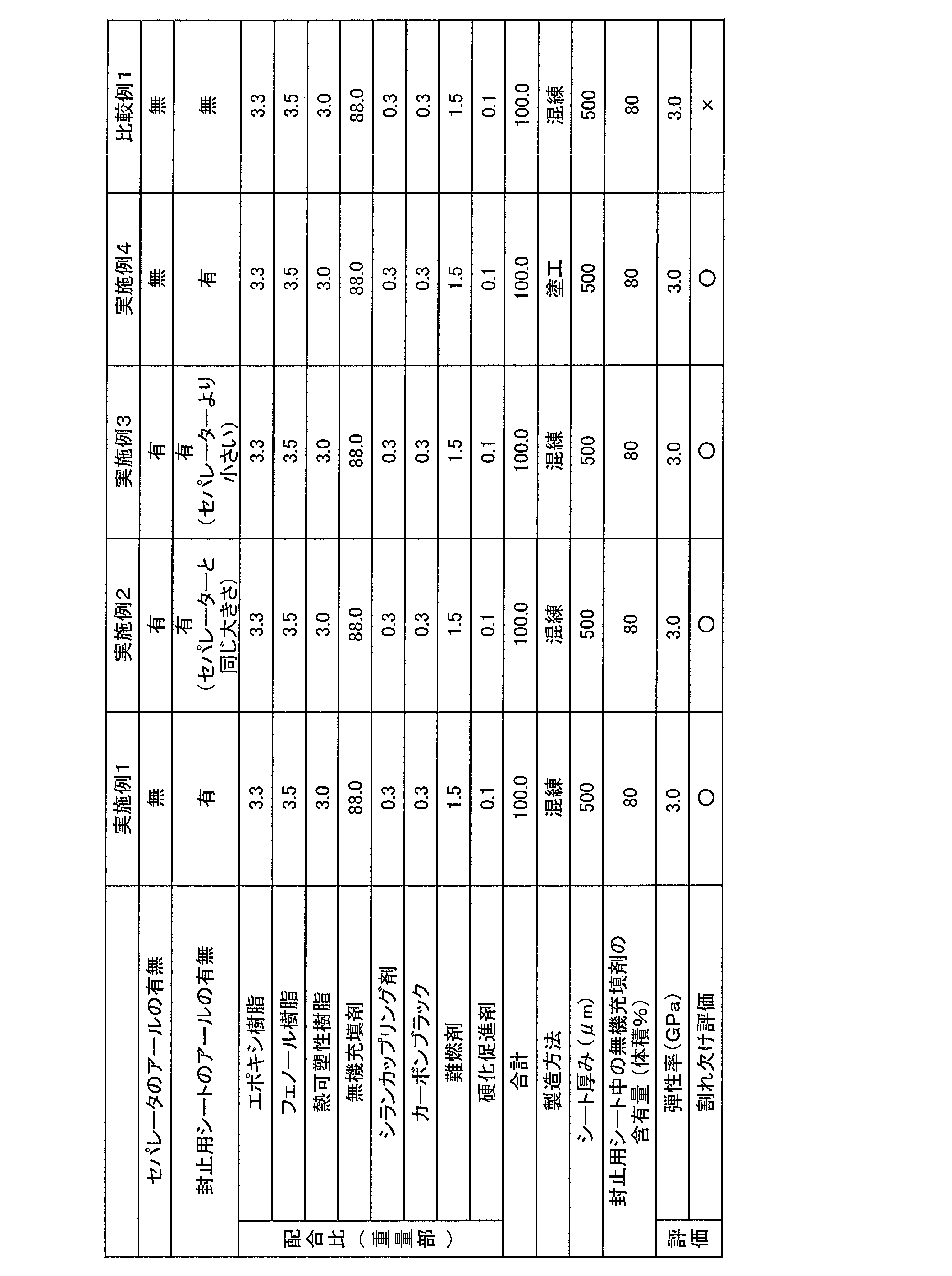
表1に記載の配合比に従い、各成分を配合し、2軸混練機により60~120℃、10分間、減圧条件下(0.01kg/cm2)で溶融混練し、混練物を調製した。次いで、得られた混練物を、平板プレス法により、シート状に形成して100mm×100mm×厚さ0.5mm(隅部にアール無し)の熱硬化性封止用シートを作製した。得られた熱硬化性封止用シートに、セパレータを貼り付けた。なお、セパレータには、三菱化学社製、製品名:MRF-50(100mm×100mm×厚さ0.05mm(隅部にアール無し))を用いた。
次に、実施例1に関しては、トムソン金型を用いて封止用シートの隅部に曲率半径が1mmのアールを形成した。なお、トムソン金型による打ち抜きは、封止用シートのみとし、セパレータは打ち抜きを行なっていない。
実施例2に関しては、トムソン金型を用いて封止用シートとセパレータとを同時に打ち抜き、封止用シートの隅部とセパレータの隅部とに曲率半径が3mmのアールを形成した。
実施例3に関しては、まず、トムソン金型を用いて封止用シートの隅部に曲率半径が5mmのアールを形成した。次に、別のトムソン金型を用いてセパレータの隅部に曲率半径が1mmのアールを形成した。なお、封止用シートの打ち抜きの際は、封止用シートのみとし、セパレータは打ち抜きを行なっていない。
比較例1に関しては、打ち抜きを行なわなかった。
実施例1~3、比較例1
表1に記載の配合比に従い、各成分を配合し、2軸混練機により60~120℃、10分間、減圧条件下(0.01kg/cm2)で溶融混練し、混練物を調製した。次いで、得られた混練物を、平板プレス法により、シート状に形成して100mm×100mm×厚さ0.5mm(隅部にアール無し)の熱硬化性封止用シートを作製した。得られた熱硬化性封止用シートに、セパレータを貼り付けた。なお、セパレータには、三菱化学社製、製品名:MRF-50(100mm×100mm×厚さ0.05mm(隅部にアール無し))を用いた。
次に、実施例1に関しては、トムソン金型を用いて封止用シートの隅部に曲率半径が1mmのアールを形成した。なお、トムソン金型による打ち抜きは、封止用シートのみとし、セパレータは打ち抜きを行なっていない。
実施例2に関しては、トムソン金型を用いて封止用シートとセパレータとを同時に打ち抜き、封止用シートの隅部とセパレータの隅部とに曲率半径が3mmのアールを形成した。
実施例3に関しては、まず、トムソン金型を用いて封止用シートの隅部に曲率半径が5mmのアールを形成した。次に、別のトムソン金型を用いてセパレータの隅部に曲率半径が1mmのアールを形成した。なお、封止用シートの打ち抜きの際は、封止用シートのみとし、セパレータは打ち抜きを行なっていない。
比較例1に関しては、打ち抜きを行なわなかった。
実施例4
表1の記載の配合に従い、溶剤(重量比で、メチルエチルケトン(MEK):トルエン=1:1)に各成分を配合し、非溶剤成分濃度90%の塗工液を得た。
次いで、得られた塗工液を、シリコーン離型処理した厚さが50μmのポリエチレンテレフタレートフィルム上に塗布し、120℃3分間、乾燥させることにより、厚さ50μmの樹脂シートを作製した。さらに作製した樹脂シートをロールラミネーターにて、90℃で貼り合わせをすることによって、100mm×100mm×厚さ0.5mm(隅部にアール無し)の熱硬化性封止用シートを作製した。得られた熱硬化性封止用シートに、セパレータを貼り付けた。なお、セパレータには、三菱化学社製、製品名:MRF-50(100mm×100mm×厚さ0.05mm(隅部にアール無し))を用いた。
次に、トムソン金型を用いて封止用シートの隅部に曲率半径が1mmのアールを形成した。なお、トムソン金型による打ち抜きは、封止用シートのみとし、セパレータは打ち抜きを行なっていない。
表1の記載の配合に従い、溶剤(重量比で、メチルエチルケトン(MEK):トルエン=1:1)に各成分を配合し、非溶剤成分濃度90%の塗工液を得た。
次いで、得られた塗工液を、シリコーン離型処理した厚さが50μmのポリエチレンテレフタレートフィルム上に塗布し、120℃3分間、乾燥させることにより、厚さ50μmの樹脂シートを作製した。さらに作製した樹脂シートをロールラミネーターにて、90℃で貼り合わせをすることによって、100mm×100mm×厚さ0.5mm(隅部にアール無し)の熱硬化性封止用シートを作製した。得られた熱硬化性封止用シートに、セパレータを貼り付けた。なお、セパレータには、三菱化学社製、製品名:MRF-50(100mm×100mm×厚さ0.05mm(隅部にアール無し))を用いた。
次に、トムソン金型を用いて封止用シートの隅部に曲率半径が1mmのアールを形成した。なお、トムソン金型による打ち抜きは、封止用シートのみとし、セパレータは打ち抜きを行なっていない。
<熱硬化性封止用シートの熱硬化前における23℃での引張貯蔵弾性率の測定>
作製したセパレータ付き熱硬化性封止用シートからセパレータを剥離した。次に、粘弾性測定装置(レオメトリックス社製:形式:RSA-II)を用いて、熱硬化性封止用シートの熱硬化前における23℃での引張貯蔵弾性率を測定した。より詳細には、サンプルサイズを長さ30.0×幅5.0×厚さ0.1mmとし、測定試料をフィルム引っ張り測定用治具にセットし、-30℃~250℃の温度域で周波数1.0Hz、歪み0.025%、昇温速度10℃/分の条件下で測定した。その結果、23での貯蔵弾性率は3.0GPaであった。
作製したセパレータ付き熱硬化性封止用シートからセパレータを剥離した。次に、粘弾性測定装置(レオメトリックス社製:形式:RSA-II)を用いて、熱硬化性封止用シートの熱硬化前における23℃での引張貯蔵弾性率を測定した。より詳細には、サンプルサイズを長さ30.0×幅5.0×厚さ0.1mmとし、測定試料をフィルム引っ張り測定用治具にセットし、-30℃~250℃の温度域で周波数1.0Hz、歪み0.025%、昇温速度10℃/分の条件下で測定した。その結果、23での貯蔵弾性率は3.0GPaであった。
<衝突時のシート割れ欠けがないことの評価>
実施例、及び、比較例のセパレータ付き熱硬化性封止用シートをコンクリート上高さ1mの場所から落下させ、隅部を衝突させた。落下試験は、23℃の条件で行なった。その後、熱硬化性封止用シートの隅部を20倍の顕微鏡で観察し、割れ欠けの有無を確認した。割れや欠けが視認できなかった場合を〇、視認できた場合を×として評価した。結果を表1に示す。
実施例、及び、比較例のセパレータ付き熱硬化性封止用シートをコンクリート上高さ1mの場所から落下させ、隅部を衝突させた。落下試験は、23℃の条件で行なった。その後、熱硬化性封止用シートの隅部を20倍の顕微鏡で観察し、割れ欠けの有無を確認した。割れや欠けが視認できなかった場合を〇、視認できた場合を×として評価した。結果を表1に示す。
10、20、30 セパレータ付き熱硬化性封止用シート
12、22、32 セパレータ
14、24、34 セパレータの隅部
16 熱硬化性封止用シート
18 熱硬化性封止用シートの隅部
25、35 熱硬化性封止用シートが形成されていない領域
12、22、32 セパレータ
14、24、34 セパレータの隅部
16 熱硬化性封止用シート
18 熱硬化性封止用シートの隅部
25、35 熱硬化性封止用シートが形成されていない領域
Claims (5)
- 隅部にアールが形成されており、前記アールの曲率半径R1が0.5~10mmの範囲内であることを特徴とする熱硬化性封止用シート。
- 請求項1に記載の熱硬化性封止用シートが、セパレータ上に積層されており、
前記セパレータの隅部上には、前記熱硬化性封止用シートが形成されていない領域が存在することを特徴とするセパレータ付き熱硬化性封止用シート。 - 請求項1に記載の熱硬化性封止用シートが、セパレータ上に積層されており、
前記セパレータと前記熱硬化性封止用シートとが、平面視で同一の形状を有していることを特徴とするセパレータ付き熱硬化性封止用シート。 - 熱硬化前における23℃での引張貯蔵弾性率が、1GPa~5GPaであることを特徴とする請求項1に記載の熱硬化性封止用シート。
- 前記熱硬化性封止用シートの熱硬化前における23℃での引張貯蔵弾性率が、1GPa~5GPaであることを特徴とする請求項2又は3に記載のセパレータ付き熱硬化性封止用シート。
Applications Claiming Priority (4)
| Application Number | Priority Date | Filing Date | Title |
|---|---|---|---|
| JP2013-069795 | 2013-03-28 | ||
| JP2013069795 | 2013-03-28 | ||
| JP2014-022235 | 2014-02-07 | ||
| JP2014022235A JP2014209564A (ja) | 2013-03-28 | 2014-02-07 | 熱硬化性封止用シート、及び、セパレータ付き熱硬化性封止用シート |
Publications (1)
| Publication Number | Publication Date |
|---|---|
| WO2014156779A1 true WO2014156779A1 (ja) | 2014-10-02 |
Family
ID=51623760
Family Applications (1)
| Application Number | Title | Priority Date | Filing Date |
|---|---|---|---|
| PCT/JP2014/057173 Ceased WO2014156779A1 (ja) | 2013-03-28 | 2014-03-17 | 熱硬化性封止用シート、及び、セパレータ付き熱硬化性封止用シート |
Country Status (3)
| Country | Link |
|---|---|
| JP (1) | JP2014209564A (ja) |
| TW (1) | TW201448136A (ja) |
| WO (1) | WO2014156779A1 (ja) |
Families Citing this family (1)
| Publication number | Priority date | Publication date | Assignee | Title |
|---|---|---|---|---|
| JP7264593B2 (ja) * | 2018-01-30 | 2023-04-25 | 日東電工株式会社 | 半導体背面密着フィルム及びダイシングテープ一体型半導体背面密着フィルム |
Citations (6)
| Publication number | Priority date | Publication date | Assignee | Title |
|---|---|---|---|---|
| JPH11297904A (ja) * | 1998-04-14 | 1999-10-29 | Nitto Denko Corp | 半導体装置 |
| JP2000058716A (ja) * | 1998-08-14 | 2000-02-25 | Toshiba Corp | 半導体装置 |
| JP2006321216A (ja) * | 2005-04-19 | 2006-11-30 | Hitachi Chem Co Ltd | 封止用シート |
| JP2012212917A (ja) * | 2007-06-07 | 2012-11-01 | Semiconductor Energy Lab Co Ltd | 半導体装置 |
| JP2012227516A (ja) * | 2011-04-05 | 2012-11-15 | Nitto Denko Corp | 封止シート、発光ダイオード装置およびその製造方法 |
| JP2013021284A (ja) * | 2011-06-14 | 2013-01-31 | Nitto Denko Corp | 封止用シートおよび光半導体素子装置 |
-
2014
- 2014-02-07 JP JP2014022235A patent/JP2014209564A/ja active Pending
- 2014-03-17 WO PCT/JP2014/057173 patent/WO2014156779A1/ja not_active Ceased
- 2014-03-26 TW TW103111308A patent/TW201448136A/zh unknown
Patent Citations (6)
| Publication number | Priority date | Publication date | Assignee | Title |
|---|---|---|---|---|
| JPH11297904A (ja) * | 1998-04-14 | 1999-10-29 | Nitto Denko Corp | 半導体装置 |
| JP2000058716A (ja) * | 1998-08-14 | 2000-02-25 | Toshiba Corp | 半導体装置 |
| JP2006321216A (ja) * | 2005-04-19 | 2006-11-30 | Hitachi Chem Co Ltd | 封止用シート |
| JP2012212917A (ja) * | 2007-06-07 | 2012-11-01 | Semiconductor Energy Lab Co Ltd | 半導体装置 |
| JP2012227516A (ja) * | 2011-04-05 | 2012-11-15 | Nitto Denko Corp | 封止シート、発光ダイオード装置およびその製造方法 |
| JP2013021284A (ja) * | 2011-06-14 | 2013-01-31 | Nitto Denko Corp | 封止用シートおよび光半導体素子装置 |
Also Published As
| Publication number | Publication date |
|---|---|
| TW201448136A (zh) | 2014-12-16 |
| JP2014209564A (ja) | 2014-11-06 |
Similar Documents
| Publication | Publication Date | Title |
|---|---|---|
| JP5735036B2 (ja) | 電子部品装置の製造方法、及び、積層シート | |
| JP6643791B2 (ja) | 中空封止用樹脂シート及び中空パッケージの製造方法 | |
| JP6735071B2 (ja) | 封止樹脂シート | |
| JP5793160B2 (ja) | 電子デバイス封止用樹脂シート及び電子デバイスパッケージの製造方法 | |
| JP6497998B2 (ja) | 封止用シートおよびパッケージの製造方法 | |
| CN105229780A (zh) | 电子部件装置的制造方法 | |
| JP2016175972A (ja) | 封止用シートおよびパッケージの製造方法 | |
| JP6379051B2 (ja) | 中空型電子デバイス封止用シート | |
| WO2014156779A1 (ja) | 熱硬化性封止用シート、及び、セパレータ付き熱硬化性封止用シート | |
| CN105684143B (zh) | 电子器件密封用树脂片及电子器件封装体的制造方法 | |
| JP5239661B2 (ja) | カバーレイフィルム | |
| JP5735030B2 (ja) | 電子デバイス封止用樹脂シート及び電子デバイスパッケージの製造方法 | |
| WO2014156777A1 (ja) | 中空型電子デバイス封止用シート、及び、中空型電子デバイスパッケージの製造方法 | |
| TWI715541B (zh) | 附分隔件之密封用片材、及半導體裝置之製造方法 | |
| WO2014188824A1 (ja) | 電子部品装置の製造方法 | |
| JP6434181B2 (ja) | 中空型電子デバイス封止用シート、及び、中空型電子デバイスパッケージの製造方法 | |
| WO2014168047A1 (ja) | セパレータ付き樹脂シート、電子部品装置の製造方法及び電子部品装置 | |
| TWI643890B (zh) | Resin sheet for hollow sealing and manufacturing method of hollow package | |
| WO2015079871A1 (ja) | 中空封止用樹脂シート、及び、中空パッケージの製造方法 | |
| JP2019083342A (ja) | セパレータ付き封止用シート、及び、半導体装置の製造方法 |
Legal Events
| Date | Code | Title | Description |
|---|---|---|---|
| 121 | Ep: the epo has been informed by wipo that ep was designated in this application |
Ref document number: 14773716 Country of ref document: EP Kind code of ref document: A1 |
|
| NENP | Non-entry into the national phase |
Ref country code: DE |
|
| 122 | Ep: pct application non-entry in european phase |
Ref document number: 14773716 Country of ref document: EP Kind code of ref document: A1 |