WO2014156511A1 - 蓄電装置およびその電極用材料 - Google Patents
蓄電装置およびその電極用材料 Download PDFInfo
- Publication number
- WO2014156511A1 WO2014156511A1 PCT/JP2014/055471 JP2014055471W WO2014156511A1 WO 2014156511 A1 WO2014156511 A1 WO 2014156511A1 JP 2014055471 W JP2014055471 W JP 2014055471W WO 2014156511 A1 WO2014156511 A1 WO 2014156511A1
- Authority
- WO
- WIPO (PCT)
- Prior art keywords
- active material
- negative electrode
- positive electrode
- quinone
- hydroquinone
- Prior art date
- Legal status (The legal status is an assumption and is not a legal conclusion. Google has not performed a legal analysis and makes no representation as to the accuracy of the status listed.)
- Ceased
Links
Images







Classifications
-
- H—ELECTRICITY
- H01—ELECTRIC ELEMENTS
- H01G—CAPACITORS; CAPACITORS, RECTIFIERS, DETECTORS, SWITCHING DEVICES, LIGHT-SENSITIVE OR TEMPERATURE-SENSITIVE DEVICES OF THE ELECTROLYTIC TYPE
- H01G11/00—Hybrid capacitors, i.e. capacitors having different positive and negative electrodes; Electric double-layer [EDL] capacitors; Processes for the manufacture thereof or of parts thereof
- H01G11/22—Electrodes
- H01G11/30—Electrodes characterised by their material
- H01G11/32—Carbon-based
- H01G11/34—Carbon-based characterised by carbonisation or activation of carbon
-
- H—ELECTRICITY
- H01—ELECTRIC ELEMENTS
- H01G—CAPACITORS; CAPACITORS, RECTIFIERS, DETECTORS, SWITCHING DEVICES, LIGHT-SENSITIVE OR TEMPERATURE-SENSITIVE DEVICES OF THE ELECTROLYTIC TYPE
- H01G11/00—Hybrid capacitors, i.e. capacitors having different positive and negative electrodes; Electric double-layer [EDL] capacitors; Processes for the manufacture thereof or of parts thereof
- H01G11/22—Electrodes
- H01G11/30—Electrodes characterised by their material
- H01G11/32—Carbon-based
- H01G11/38—Carbon pastes or blends; Binders or additives therein
-
- H—ELECTRICITY
- H01—ELECTRIC ELEMENTS
- H01G—CAPACITORS; CAPACITORS, RECTIFIERS, DETECTORS, SWITCHING DEVICES, LIGHT-SENSITIVE OR TEMPERATURE-SENSITIVE DEVICES OF THE ELECTROLYTIC TYPE
- H01G11/00—Hybrid capacitors, i.e. capacitors having different positive and negative electrodes; Electric double-layer [EDL] capacitors; Processes for the manufacture thereof or of parts thereof
- H01G11/22—Electrodes
- H01G11/30—Electrodes characterised by their material
- H01G11/32—Carbon-based
- H01G11/36—Nanostructures, e.g. nanofibres, nanotubes or fullerenes
-
- Y—GENERAL TAGGING OF NEW TECHNOLOGICAL DEVELOPMENTS; GENERAL TAGGING OF CROSS-SECTIONAL TECHNOLOGIES SPANNING OVER SEVERAL SECTIONS OF THE IPC; TECHNICAL SUBJECTS COVERED BY FORMER USPC CROSS-REFERENCE ART COLLECTIONS [XRACs] AND DIGESTS
- Y02—TECHNOLOGIES OR APPLICATIONS FOR MITIGATION OR ADAPTATION AGAINST CLIMATE CHANGE
- Y02E—REDUCTION OF GREENHOUSE GAS [GHG] EMISSIONS, RELATED TO ENERGY GENERATION, TRANSMISSION OR DISTRIBUTION
- Y02E60/00—Enabling technologies; Technologies with a potential or indirect contribution to GHG emissions mitigation
- Y02E60/13—Energy storage using capacitors
Definitions
- the present invention relates to a power storage device and a material for an electrode thereof, for example, a power storage device including a porous material carrying quinone or hydroquinone and a material for the electrode.
- Non-Patent Document 1 discloses an electrochemical capacitor using a composite of 1,2-dihydroxybenzene and activated carbon for the positive electrode and a composite of anthraquinone and activated carbon for the negative electrode.
- Non-Patent Document 2 discloses an electrochemical capacitor that uses a composite of ruthenium oxide and activated carbon for the positive electrode and a composite of anthracene and activated carbon for the negative electrode.
- Patent Document 1 discloses that a polymer bonded with a quinone compound is used for an electrode.
- Patent Document 2 a 1,4,5,8-anthracenetetron compound or a 5,7,12,14-pentacenetron compound having a hydrogen atom, an alkyl group or a halogen group is used for the positive electrode, and lithium is used for the negative electrode.
- a secondary battery is disclosed.
- Non-Patent Document 1 it is expected that a rocking chair electrochemical capacitor capable of conducting protons can be realized by using a quinone compound or a hydroquinone compound for both the positive electrode and the negative electrode.
- a quinone compound or a hydroquinone compound for both the positive electrode and the negative electrode.
- the metal can be minimized. Accordingly, for example, a power storage device that does not use rare elements or toxic substances can be realized.
- the quinone compound or hydroquinone compound is supported on the porous body, the quinone compound or hydroquinone compound is eluted from the porous body. For this reason, the lifetime of the power storage device is shortened.
- This invention is made in view of the said subject, and aims at extending the lifetime of an electrical storage apparatus.
- the present invention is an electrode material for a power storage device comprising an active material containing at least one of a quinone having a halogen group and hydroquinone, and a porous body supporting the active material.
- the porous body may include activated carbon or nanocarbon.
- the halogen group may be a chloro group.
- the present invention is a power storage device including an electrode material in at least one of a positive electrode and a negative electrode.
- the present invention provides a positive electrode active material containing at least one of quinone and hydroquinone, a positive electrode porous material carrying the positive electrode active material, a negative electrode active material containing at least one of quinone and hydroquinone, and the negative electrode A negative electrode containing an active material-carrying negative electrode, and an electrolyte provided between the positive electrode and the negative electrode, and included in at least one of the positive electrode active material and the negative electrode active material
- at least one of the quinone and hydroquinone has a halogen group.
- At least one of quinone and hydroquinone contained in the negative electrode active material may contain more benzene rings than at least one of quinone and hydroquinone contained in the positive electrode active material.
- At least one of quinone and hydroquinone contained in the negative electrode active material may have the halogen group.
- At least one of quinone and hydroquinone contained in the negative electrode active material and at least one of quinone and hydroquinone contained in the positive electrode active material can both have the halogen group.
- the life of the power storage device can be extended.
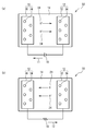
- FIG. 1 (a) and FIG.1 (b) are the schematic diagrams of the electrical storage apparatus which concerns on embodiment of this invention.
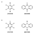
- FIG. 2A is a diagram illustrating examples of the positive electrode active material and the negative electrode active material in a discharged state
- FIG. 2B is a diagram illustrating examples of the positive electrode active material and the negative electrode active material in a charged state.
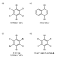
- FIG. 3A to FIG. 3D are diagrams showing chemical formulas of examples of hydroquinone contained in the positive electrode active material.
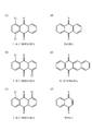
- FIG. 4A to FIG. 4F are diagrams (part 1) illustrating chemical formulas of examples of quinones included in the negative electrode active material.
- FIG. 5A to FIG. 5D are diagrams (part 2) illustrating chemical formulas of examples of quinones included in the negative electrode active material.
- FIG. 6A to FIG. 6D are diagrams (part 3) illustrating chemical formulas of examples of quinones included in the negative electrode active material.
- FIG. 7 is a diagram illustrating the power storage device according to the first to fifth embodiments.
- FIG. 8 is a diagram illustrating the voltage with respect to the capacitance in the first embodiment.
- FIG. 9 is a diagram illustrating the potential with respect to time in the first embodiment.
- FIG. 10 is a diagram illustrating a potential with respect to time of each cycle in the first embodiment.
- FIG. 11 is a diagram illustrating a potential with respect to time of each cycle in the second embodiment.
- FIG. 12 is a diagram illustrating the potential with respect to time of each cycle in the third embodiment.
- FIG. 13 is a diagram illustrating the potential with respect to time of each cycle in the fourth embodiment.
- FIG. 14 is a diagram showing the energy density with respect to the cycle in Example 4.
- FIG. 15 is a diagram illustrating the potential with respect to time of each cycle in the fifth embodiment.
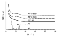
- FIG. 16 is a diagram showing the results of X-ray diffraction analysis.
- FIG. 17 is a diagram showing the pore area distribution with respect to the pore radius.
- FIG. 18 is a diagram showing dV m / dr m with respect to the pore radius.
- FIG. 19 is a diagram showing the area distribution with respect to the pore radius.
- FIG. 20 is a schematic diagram showing quinones in the pores.
- FIG. 21A is a diagram showing the voltage with respect to time in Example 6, and FIG.
- FIG. 21B is a diagram showing the energy density with respect to the cycle.
- FIG. 22A is a diagram showing the voltage with respect to time in Example 7, and
- FIG. 22B is a diagram showing the energy density with respect to the cycle.
- FIG. 23A shows the molecular formula of hydroquinone, and
- FIG. 23B shows the discharge capacity rate with respect to the number of cycles.
- the power storage device 50 includes a positive electrode 10, a negative electrode 12, and an electrolyte 14.
- the positive electrode 10 includes a positive electrode porous body 30 and a positive electrode active material 34.
- the positive electrode porous body 30 carries a positive electrode active material 34.
- the negative electrode 12 includes a negative electrode porous body 32 and a negative electrode active material 36.
- the negative electrode porous body 32 carries a negative electrode active material 36. Referring to FIG. 1A, when charging power storage device 50, DC power supply 16 is connected so that a positive voltage is applied to positive electrode 10 and a negative voltage is applied to negative electrode 12.
- a current I1 flows from the negative electrode 12 to the positive electrode 10 via the DC power supply 16.
- Proton 24 (H + ) is conducted from the positive electrode 10 to the negative electrode 12 in the electrolyte 14.
- load 18 is connected between positive electrode 10 and negative electrode 12.
- a current I2 flows from the positive electrode 10 to the negative electrode 12 in the load 18.
- Proton 24 (H + ) is conducted from the negative electrode 12 to the positive electrode 10 in the electrolyte 14.
- FIG. 2A is a diagram illustrating examples of the positive electrode active material and the negative electrode active material in a discharged state
- FIG. 2B is a diagram illustrating examples of the positive electrode active material and the negative electrode active material in a charged state.
- the positive electrode active material 34 is tetrachlorohydroquinone
- the negative electrode active material 36 is anthraquinone.
- the positive electrode active material 34 is hydroquinone in a discharged state, is quinone in a charged state, and is in a mixed state of quinone and hydroquinone in the middle of discharging or charging.
- the negative electrode active material 36 is quinone in a discharged state, hydroquinone in a charged state, and is a mixed state of hydroquinone and quinone during discharge or charging.
- the quinone and / or hydroquinone as the positive electrode active material 34 and the negative electrode active material 36 are supported on the positive electrode porous body 30 and the negative electrode porous body 32 such as activated carbon.
- the power storage performance deteriorates.
- the present inventors considered that quinone and / or hydroquinone would elute into the electrolyte 14 as a cause of the deterioration of the electricity storage performance.
- quinone and / or hydroquinone have a halogen group. Since the halogen group has a large electron withdrawing property, the intermolecular force with the functional group such as carbon of the positive electrode porous body 30 and the negative electrode porous body 32 is increased. For this reason, quinone and / or hydroquinone are difficult to elute into the electrolyte 14.
- the electrode material included in at least one of the positive electrode 10 and the negative electrode 12 of the power storage device includes an active material containing at least one of a quinone having a halogen group and hydroquinone, a porous body supporting the active material, including. This makes it difficult for quinone and / or hydroquinone to elute into the electrolyte 14. Thus, the life of the power storage device can be extended.
- the positive electrode 10 includes a positive electrode active material 34 containing at least one of quinone and hydroquinone, and a positive electrode porous body 30 supporting the positive electrode active material 34.
- the negative electrode 12 includes a negative electrode active material 36 containing at least one of quinone and hydroquinone, and a negative electrode porous body 32 that supports the negative electrode active material 36.
- at least one of quinone and hydroquinone contained in at least one of the positive electrode active material 34 and the negative electrode active material 36 has a halogen group. Accordingly, a power storage device with high energy density and a long lifetime can be provided.
- the quinone and / or hydroquinone used in this embodiment is a cyclic organic compound, and includes, for example, one or more benzene rings.
- the quinone and / or hydroquinone contained in the positive electrode active material 34 preferably has few benzene rings in order to lower the reaction potential.
- the quinone and / or hydroquinone contained in the negative electrode active material 36 preferably has many benzene rings in order to increase the reaction potential.
- the quinone and / or hydroquinone contained in the positive electrode active material 34 preferably has fewer benzene rings than the negative electrode active material 36.
- the quinone and / or hydroquinone contained in the positive electrode active material 34 preferably has one benzene ring
- the quinone and / or hydroquinone contained in the negative electrode active material 36 preferably contains three or more benzene rings.
- quinone and / or hydroquinone in the electrolyte 14 due to ⁇ - ⁇ interaction between the benzene ring of quinone and / or hydroquinone and the benzene ring of the porous body. Elution is difficult. Therefore, it is preferable that quinone and / or hydroquinone contain many benzene rings. However, as described above, the quinone and / or hydroquinone contained in the positive electrode active material 34 preferably has few benzene rings. For this reason, the ⁇ - ⁇ interaction between the positive electrode active material 34 and the positive electrode porous body 30 is reduced. Therefore, the quinone and / or hydroquinone contained in the positive electrode active material 34 preferably has a halogen group.
- FIGS. 3A to 3D are diagrams showing chemical formulas of examples of hydroquinone contained in the positive electrode active material.
- the positive electrode active material 34 for example, tetrachlorohydroquinone, 2,5 dichloro 3,5 ethylhydroquinone, or naphthohydroquinone can be used.
- the positive electrode active material 34 may be hydroquinone in which R in the chemical formula shown in FIG. 3D is any one of a halogen group, an alkyl group, and a hydrogen atom.
- 3A and 3B are examples of FIG. 3D.
- 4 (a) to 6 (d) are diagrams showing chemical formulas of examples of quinones contained in the negative electrode active material.
- 4 (a) to 4 (f) as the negative electrode active material 36, for example, 1,4-dichloroanthraquinone, 1,5-dichloroanthraquinone, 1,8-dichloroanthraquinone, anthraquinone, 5,12- Naphthacenequinone or naphthoquinone can be used.
- 5,7,12,14-pentacentetron, 1,2,4,8,9,11-hexachloro 5,7,12,14-pentacentetron 1,2,3,4,8,9,10,11-octachloro 5,7,12,14-pentacentetron or 1,2,3,4,6,8,9,10,11,13-octachloro 5,7,12,14-pentacentetron can be used.
- the negative electrode active material 36 may be hydroquinone in which R in the chemical formulas shown in FIGS. 6A to 6D is any one of a halogen group, an alkyl group, and a hydrogen atom.
- FIG. 4F is an example of FIG. FIG. 4 (e) is an example of FIG. 6 (b).
- FIG.5 (b) to FIG.5 (d) is an example of FIG.6 (c).
- FIG. 4A to FIG. 4D are examples of FIG. 6D.
- the arrangement and number of ketone structures and halogen groups are arbitrary.
- hydroquinone the arrangement and number of OH groups and halogen groups are arbitrary.
- the quinone and / or hydroquinone may have at least one of an alkyl group, a vinyl group, and an aryl group. Arrangement and number of at least one of the alkyl group, vinyl group and aryl group are arbitrary.
- the halogen group may be at least one of a fluoro group, a chloro group, a bromo group, an iodo group, and an astero group.
- a chloro group having moderate electron withdrawing properties is preferable.
- the diameter of the positive electrode porous body 30 and / or the negative electrode porous body 32 is, for example, 2 ⁇ m to 100 ⁇ m.
- the positive electrode porous body 30 and / or the negative electrode porous body 32 preferably have pores with a radius of 3 nm or less.
- the positive electrode porous body 30 and / or the negative electrode porous body 32 preferably contains activated carbon or nanometer-size carbon (nanocarbon) so that a ⁇ - ⁇ interaction occurs with quinone and / or hydroquinone. By agglomerating nanocarbon, it has voids and becomes a porous body. Examples of the nanocarbon include at least one of graphene, carbon nanotube, and carbon nanofiber.
- the electrolyte 14 a water-soluble electrolyte, a solid electrolyte, and an organic electrolyte can be used.
- the electrolyte 14 is preferably acidic with a pH of 7 or higher.
- the electrolyte 14 preferably contains an acid such as sulfuric acid, nitric acid or hydrochloric acid. In order to extend the life of the power storage device, it is preferable that the oxygen concentration in the electrolyte 14 is low.
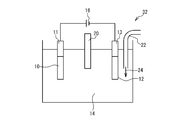
- FIG. 7 is a diagram illustrating the power storage device according to the first to fifth embodiments.
- the power storage device 52 includes a positive electrode 10, a current collector 11, a negative electrode 12, a current collector 13, an electrolyte 14, a reference electrode 20, and a tube 22.
- the positive electrode 10 and the negative electrode 12 are connected to a DC power source 16 or a load via current collectors 11 and 13, respectively.
- the current collector 11 is an Au (gold) mesh
- the current collector 13 is an Au (gold) mesh.
- the electrolyte 14 is a sulfuric acid (H 2 SO 4 ) aqueous solution.
- the reference electrode 20 is a mixture of Ag (silver) and AgCl (silver chloride).
- the tube 22 supplies nitrogen gas into the electrolyte 14 for bubbling. Thereby, oxygen in the electrolyte 14 is degassed.
- the manufacturing method of the positive electrode 10 and the negative electrode 12 in Examples 1 to 5 is as follows. Quinone or hydroquinone and activated carbon are dispersed in an organic solvent (acetone in the examples). The temperature is higher than room temperature (about 70 ° C. in the embodiment), and the organic solvent is evaporated. As a result, quinone or hydroquinone is supported on the activated carbon. Activated carbon and a binder (PTFE in the examples) are mixed. Molding a mixture of activated carbon and binder.
- Table 1 is a table showing the material of the positive electrode 10, the material of the negative electrode 12, the weight ratio of the positive electrode 10 and the negative electrode 12, the sulfuric acid concentration of the electrolyte 14, the reference electrode 20 and the C rate in Example 1.
- tetrachlorohydroquinone Chloranol : TCHQ
- activated carbon 1 and PTFE polytetrafluoroethylene
- Anthraquinone (AQ) activated carbon 1 and PTFE were used for the negative electrode 12.
- Activated carbon 1 is Maxsorb (registered trademark), which is relatively expensive but has many pores with a radius of 3 nm or less.
- the weight ratio between the positive electrode 10 and the negative electrode 12 is 1: 1.
- the sulfuric acid concentration of the electrolyte 14 is 0.5 mol / liter.
- the reference electrode 20 is a mixture of Ag and AgCl.
- the C rate for the measurement of the charge characteristic and the discharge characteristic was set to 5C based on the AQ standard.
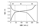
- FIG. 8 is a diagram showing the voltage with respect to the capacitance in the first embodiment.
- a solid line indicates a voltage between the positive electrode 10 and the negative electrode 12 during charging, and a broken line indicates a voltage between the positive electrode 10 and the negative electrode 12 during discharging.
- the capacity is expressed per unit mass of the positive electrode 10. Referring to FIG. 8, at the time of charging, the voltage suddenly rises to about 40 mAh / g, the slope becomes gentle from 40 mAh / g to about 180 mAh / g, and suddenly rises again at 180 mAh / g or more.
- the voltage rapidly decreases to about 40 mAh / g, gradually decreases from 40 mAh / g to about 150 mAh / g, rapidly decreases again at 150 mAh / g or more, and reaches 0 V at about 220 mAh / g.
- FIG. 9 is a diagram showing the potential with respect to time in Example 1.
- the solid line indicates the potential of the positive electrode 10 with respect to the reference electrode 20, and the broken line indicates the potential of the negative electrode 12 with respect to the reference electrode 20.
- the charging time is from 0 second to about 650 seconds, and the discharging time is from about 650 seconds to about 1250 seconds.
- the average potential of the positive electrode 10 is 0.501V, and the average potential of the negative electrode 12 is ⁇ 0.159V.
- the reaction potential is about 0.65V.
- the potential difference between the positive electrode 10 and the negative electrode 12 in FIG. 9 corresponds to the voltage in FIG.
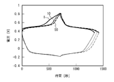
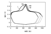
- FIG. 10 is a diagram showing the potential with respect to time of each cycle in the first embodiment.
- the numbers attached to the curves in FIG. 10 indicate cycles.
- the cycle is the number of times charging and discharging are repeated.
- the thick line indicates the potential of the positive electrode 10 with respect to the reference electrode 20, and the thin line indicates the potential of the negative electrode 12 with respect to the reference electrode 20. The same applies to FIGS. 11 to 13 and FIG.
- Table 2 is a table
- the energy density is about 14 Wh / kg to about 18 Wh / kg from the first cycle to the 50th cycle.
- E (energy density) 1/2 ⁇ C (EDLC capacity) ⁇ V (voltage) 2 .
- the energy density and the EDLC capacity are increased compared to the 1st cycle.
- the 50th cycle and the 10th cycle have almost the same energy density and EDLC capacity.
- the energy density is almost the same up to the 100th cycle. Nitrogen gas bubbling was stopped at the 100th cycle. In the 150th cycle, the energy density decreases. Thus, the lifetime can be extended by reducing the oxygen concentration in the electrolyte 14 by nitrogen bubbling.
- Table 3 is a table showing the material of the positive electrode 10, the material of the negative electrode 12, the weight ratio of the positive electrode 10 and the negative electrode 12, the sulfuric acid concentration of the electrolyte 14, the reference electrode 20 and the C rate in Example 2.
- the weight ratio between the positive electrode 10 and the negative electrode 12 was set to 1: 1.2.
- C rate was based on tetrachlorohydroquinone.
- the other materials used, the method for producing the positive electrode 10 and the negative electrode 12, and the method for measuring the charge characteristics and the discharge characteristics are the same as those in Example 1, and the description thereof is omitted.
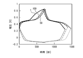
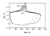
- FIG. 11 is a diagram illustrating a potential with respect to time of each cycle in the second embodiment.
- Table 4 is a table
- the energy density is about 10 Wh / kg to 13 Wh / kg. Moreover, the energy density has hardly decreased until the 100th cycle.
- Example 2 is 10 Wh / kg or more although energy density is smaller than Example 1.
- Table 5 is a table showing the material of the positive electrode 10, the material of the negative electrode 12, the weight ratio of the positive electrode 10 and the negative electrode 12, the sulfuric acid concentration of the electrolyte 14, the reference electrode 20 and the C rate in Example 3.
- the concentration of the electrolyte 14 was set to 1.75 mol / liter.
- the other materials used, the method for producing the positive electrode 10 and the negative electrode 12, and the method for measuring the charge characteristics and the discharge characteristics are the same as those in Example 2, and the description thereof is omitted.
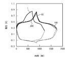
- FIG. 12 is a diagram illustrating the potential with respect to time of each cycle in the third embodiment.
- Table 6 is a table
- FIG. 12 is a diagram illustrating the potential with respect to time of each cycle in the third embodiment.
- the energy density is about 13 Wh / kg to 18 Wh / kg. Moreover, the energy density has hardly decreased until the 150th cycle. In Example 3, the energy density is the same as in Example 1 even if the C rate is doubled compared to Example 1.
- the energy density and the C rate can be optimized by appropriately setting the ratio between the positive electrode 10 and the negative electrode 12 and the sulfuric acid concentration of the electrolyte 14.
- Table 7 is a table showing the material of the positive electrode 10, the material of the negative electrode 12, the weight ratio of the positive electrode 10 and the negative electrode 12, the sulfuric acid concentration of the electrolyte 14, the reference electrode 20 and the C rate in Example 4.
- activated carbon 2 was used as the activated carbon for positive electrode 10 and negative electrode 12.
- insulator pattern charcoal is used as the activated carbon 2. Insulator pattern charcoal is less expensive than Maxsorb (registered trademark), but has few pores with a radius of 3 nm or less.
- Carbon black (KB) is added to the positive electrode 10 and the negative electrode 12. When carbon black is added as in a general power storage device, the capacity is improved.
- the other materials used, the method for producing the positive electrode 10 and the negative electrode 12, and the method for measuring the charge characteristics and the discharge characteristics are the same as those in Example 1, and the description thereof is omitted.
- FIG. 13 is a diagram showing the potential with respect to time of each cycle in Example 4.
- FIG. 14 is a diagram showing the energy density with respect to the cycle in Example 4. Referring to FIGS. 13 and 14, the energy density is 8 Wh / kg to 12 Wh / kg. Although the energy density decreases with the number of cycles, the energy density is about 80% in the first cycle even at the 1800th cycle. Thus, the decrease in energy density due to the charge / discharge cycle is small.
- Example 4 a large energy density of about 10 Wh / kg can be realized even if inexpensive cocoon pattern charcoal is used. Further, even when charging / discharging for about 2000 cycles is performed, the deterioration is small.
- Table 8 is a table showing the material of the positive electrode 10, the material of the negative electrode 12, the weight ratio of the positive electrode 10 and the negative electrode 12, the sulfuric acid concentration of the electrolyte 14, the reference electrode 20 and the C rate in Example 5.
- 1,5-dichloroanthraquinone (DCAQ) is used as the negative electrode active material.
- C rate is based on 1,5-dichloroanthraquinone.
- the other materials used, the method for producing the positive electrode 10 and the negative electrode 12, and the method for measuring the charge characteristics and the discharge characteristics are the same as those in Example 1, and the description thereof is omitted.
- FIG. 15 is a diagram illustrating the potential with respect to time of each cycle in the fifth embodiment.
- Table 9 is a table
- the energy density is about 9 Wh / kg to about 16 Wh / kg.
- the energy density is improved up to the 200th cycle.
- the energy density is slightly reduced after the 10th cycle, whereas in Example 5, the energy density is improved up to the 200th cycle.
- the negative electrode active material has a halogen group in addition to the positive electrode active material, thereby suppressing elution of the negative electrode active material into the electrolyte.
- 1,8-dichloroanthraquinone was used as the active material, it was difficult to suppress the solute in the electrolyte 14 compared to 1,5-dichloroanthraquinone. From this result, it is considered that the halogen group is preferably arranged at a point-symmetrical position in quinone or hydroquinone.
- the positive electrode active material and / or the negative electrode active material when the positive electrode active material and / or the negative electrode active material has a halogen group, elution of the positive electrode active material and / or the negative electrode active material into the electrolyte is suppressed, and the charge / discharge cycle characteristics are improved. It can be improved.
- the quinone and / or hydroquinone mainly contained in the negative electrode active material preferably has a halogen group because it has a small number of benzene rings.
- both the quinone and / or hydroquinone mainly contained in the negative electrode active material and the quinone and / or hydroquinone mainly contained in the positive electrode active material preferably have a halogen group.
- the energy density of about 20 Wh / kg which is the energy density of the lead secondary battery, can be realized by using rare elements and highly toxic elements.
- the porous body, the active material and the electrolyte By optimizing the porous body, the active material and the electrolyte, a higher energy density can be realized.
- FIG. 16 is a diagram showing the results of X-ray diffraction analysis. Referring to FIG. 16, crystal signals are observed for AQ and NQ. Since the activated carbon 1 has a large number of pores, the signal becomes a gentle signal. In the complex of AQ and activated carbon 1, and the complex of NQ and activated carbon 1, the signal is gentle. This indicates that the AQ or NQ crystal supported on the activated carbon 1 has a nanometer size.
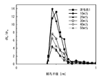
- complex which added 10 wt% to 50 wt% AQ to activated carbon 1 were produced.
- the area distribution per unit weight of the activated carbon 1 with respect to the pore radius was measured using BJH (Barrett-Joyner-Halenda).
- the dV m / dr m with respect to the pore radius was measured using a nitrogen adsorption / desorption measurement MP (Micropore analysis) method.
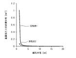
- the area distribution per unit weight with respect to the pore radius of activated carbon 2 (coconut pattern charcoal) was measured using the BJH method.
- FIG. 17 is a diagram showing the area distribution with respect to the pore radius.
- FIG. 18 is a diagram showing dV m / dr m with respect to the pore radius.
- dV m / dr m As the AQ concentration increases, the number of pores having a small radius decreases. Further, dV m / dr m decreases.
- dV m / dr m (cm 3 ⁇ g ⁇ 1 ⁇ nm ⁇ 1 ) is a value twice as large as each pore area. This indicates that AQ particles grow in the pores when the AQ concentration increases.
- FIG. 19 is a diagram showing the area distribution with respect to the pore radius.
- the solid line indicates activated carbon 1 and the broken line indicates activated carbon 2.
- the activated carbon 1 has more pores having a radius of 3 nm or less than the activated carbon 2, and particularly has very many pores having a radius of 2 nm or less.
- the reason why the energy density of Example 1 is higher than that of Example 4 is considered to be because there are many pores having a small radius (for example, micropores having a diameter of 2 nm or less).
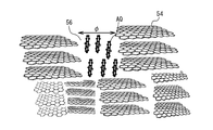
- FIG. 20 is a schematic diagram showing quinones in the pores. Pores 56 are formed in the molecules 54 of the porous body. AQ particles are formed as quinone and / or hydroquinone in the pores 56. As described above, quinone and / or hydroquinone which are active materials are crystallized in the pores 56 of the porous body.
- the porous body can carry more quinone and / or hydroquinone in the pores.
- the energy density of the power storage device can be improved.
- the area of the micropores having a diameter of 2 nm or less is preferably 50% or more of the total surface area, and more preferably 70% or more. Thereby, the energy density of an electrical storage apparatus can be improved.
- Example 6 is an example in which charge / discharge characteristics of the power storage device having the same configuration as Table 1 of Example 1 were measured up to 1000 cycles.
- FIG. 21A is a diagram showing the voltage with respect to time in Example 6, and
- FIG. 21B is a diagram showing the energy density with respect to the cycle.
- the numbers attached to the curves in FIG. 21 (a) indicate the number of cycles.
- the voltage when the cell voltage is 0 V is increased to the positive electrode side as compared to the 100th cycle (see arrow). This indicates that energy loss is caused by the deterioration of the negative electrode.
- the maximum energy density is about 19 Wh / kg, and then the energy density decreases as the number of cycles increases.
- the energy density at the 1000th cycle is about 71% of the maximum energy density.
- the charge / discharge characteristics are good up to the 1000th cycle.
- the capacities of the negative electrode and the positive electrode were measured from the charge / discharge curve at the 50th cycle.
- the capacity of the negative electrode was 199 mAh / g. This is 77% of the anthraquinone theoretical capacity of 257 mAh / g.
- the capacity of the positive electrode was 186 mAh / g, which is 86% of the theoretical capacity of tetrachlorohydroquinone 216 mAh / g. Thus, a capacity close to the theoretical capacity could be obtained.
- Example 7 is an example in which charge / discharge characteristics of the power storage device having the same configuration as Table 8 of Example 5 were measured up to 1000 cycles.
- FIG. 22A is a diagram showing the voltage with respect to time in Example 7
- FIG. 22B is a diagram showing the energy density with respect to the cycle.
- the numbers attached to the curves in FIG. 22 (a) indicate the number of cycles.
- FIG. 22B shows the sixth embodiment and the seventh embodiment.
- the charge / discharge characteristics hardly change between the 100th cycle and the 1000th cycle.
- the maximum energy density of Example 7 is about 12 Wh / kg.
- the energy density at the 1000th cycle is about 95% of the maximum energy density.
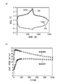
- the positive electrode active material was hydroquinone (Comparative Example 1) or tetrachlorohydroquinone (Example 8), and the negative electrode was only activated carbon. Others are the same as in the first embodiment.
- FIG. 23A shows the molecular formula of hydroquinone. As shown in FIG. 23 (a), hydroquinone has no chloro group bonded to the tetrachloroquinone of FIG. 2 (b).
- FIG. 23B is a diagram showing the discharge capacity rate with respect to the number of cycles. As shown in FIG. 23B, in Comparative Example 1, the discharge capacity rate decreases as the number of cycles increases. On the other hand, in Example 8, the discharge capacity rate hardly changes even when the number of cycles increases. Thus, when an active material has a halogen group, a high potential reaction and cycling characteristics can be made compatible.
Landscapes
- Engineering & Computer Science (AREA)
- Power Engineering (AREA)
- Chemical & Material Sciences (AREA)
- Materials Engineering (AREA)
- Microelectronics & Electronic Packaging (AREA)
- Battery Electrode And Active Subsutance (AREA)
- Electric Double-Layer Capacitors Or The Like (AREA)
- Secondary Cells (AREA)
Abstract
Description
有機溶剤(実施例ではアセトン)にキノンまたはヒドロキノンと活性炭とを分散させる。
室温より高温(実施例では約70℃)とし、有機溶剤を蒸発させる。これにより、活性炭にキノンまたはヒドロキノンが担持される。
活性炭と結合剤(実施例ではPTFE)を混合する。
活性炭と結合剤との混合体を成型する。









12 負極
14 電解質
30 正極多孔質体
32 負極多孔質体
34 正極活物質
36 負極活物質
56 細孔
Claims (8)
- ハロゲン基を有するキノンおよびヒドロキノンの少なくとも一方を含む活物質と、
前記活物質を担持した多孔質体と、
を含むことを特徴とする蓄電装置の電極用材料。 - 前記多孔質体は、活性炭またはナノカーボンを含むことを特徴とする請求項1記載の蓄電装置の電極用材料。
- 前記ハロゲン基はクロロ基であることを特徴とする請求項1または2記載の蓄電装置の電極用材料。
- 請求項1から3のいずれか一項記載の蓄電装置の電極用材料を正極および負極の少なくとも一方に含むことを特徴とする蓄電装置。
- キノンおよびヒドロキノンの少なくとも一方を含む正極活物質と、前記正極活物質を担持した正極多孔質体と、を含む正極と、
キノンおよびヒドロキノンの少なくとも一方を含む負極活物質と、前記負極活物質を担持した負極多孔質体と、を含む負極と、
前記正極と前記負極との間に設けられた電解質と、
を具備し、
前記正極活物質と前記負極活物質との少なくとも一方に含まれる前記キノンおよびヒドロキノンの少なくとも一方は、ハロゲン基を有することを特徴とする蓄電装置。 - 前記負極活物質に含まれるキノンおよびヒドロキノンの少なくとも一方は、前記正極活物質に含まれるキノンおよびヒドロキノンの少なくとも一方よりベンゼン環を多く含むことを特徴とする請求項5記載の蓄電装置。
- 前記負極活物質に含まれるキノンおよびヒドロキノンの少なくとも一方は、前記ハロゲン基を有することを特徴とする請求項5または6記載の蓄電装置。
- 前記負極活物質に含まれるキノンおよびヒドロキノンの少なくとも一方と、前記正極活物質に含まれるキノンおよびヒドロキノンの少なくとも一方と、はともに前記ハロゲン基を有することを特徴とする請求項5または6記載の蓄電装置。
Priority Applications (4)
| Application Number | Priority Date | Filing Date | Title |
|---|---|---|---|
| KR1020157026262A KR101834623B1 (ko) | 2013-03-28 | 2014-03-04 | 축전 장치 및 그 전극용 재료 |
| CN201480017828.6A CN105247639B (zh) | 2013-03-28 | 2014-03-04 | 蓄电装置及其电极材料 |
| JP2015508220A JP6158308B2 (ja) | 2013-03-28 | 2014-03-04 | 蓄電装置およびその電極用材料 |
| US14/773,425 US9620297B2 (en) | 2013-03-28 | 2014-03-04 | Electricity storage device and electrode material therefor |
Applications Claiming Priority (2)
| Application Number | Priority Date | Filing Date | Title |
|---|---|---|---|
| JP2013070369 | 2013-03-28 | ||
| JP2013-070369 | 2013-03-28 |
Publications (1)
| Publication Number | Publication Date |
|---|---|
| WO2014156511A1 true WO2014156511A1 (ja) | 2014-10-02 |
Family
ID=51623501
Family Applications (1)
| Application Number | Title | Priority Date | Filing Date |
|---|---|---|---|
| PCT/JP2014/055471 Ceased WO2014156511A1 (ja) | 2013-03-28 | 2014-03-04 | 蓄電装置およびその電極用材料 |
Country Status (5)
| Country | Link |
|---|---|
| US (1) | US9620297B2 (ja) |
| JP (1) | JP6158308B2 (ja) |
| KR (1) | KR101834623B1 (ja) |
| CN (1) | CN105247639B (ja) |
| WO (1) | WO2014156511A1 (ja) |
Cited By (4)
| Publication number | Priority date | Publication date | Assignee | Title |
|---|---|---|---|---|
| JP2016170955A (ja) * | 2015-03-12 | 2016-09-23 | 株式会社リコー | 二次電池 |
| JP2019125679A (ja) * | 2018-01-16 | 2019-07-25 | 株式会社トーキン | 電極ペースト、電気二重層キャパシタ及びその製造方法、並びにゲル状電解液 |
| JP2023098109A (ja) * | 2021-12-28 | 2023-07-10 | 国立大学法人東北大学 | レドックスキャパシタおよびレドックスキャパシタシステム |
| WO2024180819A1 (ja) * | 2023-03-01 | 2024-09-06 | 国立大学法人東北大学 | 電極用複合材料、蓄電装置、および電極用複合材料の製造方法 |
Families Citing this family (17)
| Publication number | Priority date | Publication date | Assignee | Title |
|---|---|---|---|---|
| ES2785095T3 (es) | 2011-12-21 | 2020-10-05 | Univ California | Red a base de carbono corrugada interconectada |
| AU2013230195B2 (en) | 2012-03-05 | 2017-04-20 | The Regents Of The University Of California | Capacitor with electrodes made of an interconnected corrugated carbon-based network |
| KR102443607B1 (ko) | 2014-06-16 | 2022-09-16 | 더 리전트 오브 더 유니버시티 오브 캘리포니아 | 하이브리드 전기화학 전지 |
| WO2016081638A1 (en) | 2014-11-18 | 2016-05-26 | The Regents Of The University Of California | Porous interconnected corrugated carbon-based network (iccn) composite |
| US10655020B2 (en) | 2015-12-22 | 2020-05-19 | The Regents Of The University Of California | Cellular graphene films |
| WO2017127539A1 (en) | 2016-01-22 | 2017-07-27 | The Regents Of The University Of California | High-voltage devices |
| AU2017238201B2 (en) | 2016-03-23 | 2022-01-27 | Nanotech Energy, Inc. | Devices and methods for high voltage and solar applications |
| US10622163B2 (en) * | 2016-04-01 | 2020-04-14 | The Regents Of The University Of California | Direct growth of polyaniline nanotubes on carbon cloth for flexible and high-performance supercapacitors |
| US11097951B2 (en) | 2016-06-24 | 2021-08-24 | The Regents Of The University Of California | Production of carbon-based oxide and reduced carbon-based oxide on a large scale |
| JP7109790B2 (ja) | 2016-08-31 | 2022-08-01 | ザ リージェンツ オブ ザ ユニバーシティ オブ カリフォルニア | 炭素系材料を含むデバイス及びその製造 |
| KR102093998B1 (ko) * | 2017-04-20 | 2020-03-26 | 서울대학교산학협력단 | 이차 전지용 전극 활물질 및 이를 포함하는 이차 전지 |
| CN110892572B (zh) | 2017-07-14 | 2023-02-17 | 加利福尼亚大学董事会 | 用碳纳米点制备高导电多孔石墨烯用于超级电容器应用的简单方法 |
| CN109411754A (zh) * | 2017-08-17 | 2019-03-01 | 江苏中安环能新能源科技有限公司 | 一种新型全醌水体系二次电池 |
| JP6656697B2 (ja) * | 2018-06-20 | 2020-03-04 | 国立大学法人東北大学 | 発電池用の負極、胃酸電池、金属イオン二次電池、システム、及び、電池の使用方法 |
| US10938032B1 (en) | 2019-09-27 | 2021-03-02 | The Regents Of The University Of California | Composite graphene energy storage methods, devices, and systems |
| CN115117467B (zh) * | 2022-07-04 | 2025-07-11 | 常州大学 | 基于二羟基萘二酮衍生物的酸性水系全有机对称电池 |
| CN116470109B (zh) * | 2023-04-23 | 2026-03-17 | 中国科学技术大学 | 水系有机-氢气质子电池 |
Citations (4)
| Publication number | Priority date | Publication date | Assignee | Title |
|---|---|---|---|---|
| JPH0656989A (ja) * | 1992-03-03 | 1994-03-01 | Osaka Gas Co Ltd | 酸化還元性ポリマーおよびその製造方法 |
| JPH10294107A (ja) * | 1997-04-18 | 1998-11-04 | Matsushita Electric Ind Co Ltd | アルカリ蓄電池用負極活物質とこれを用いた電池 |
| JP2004043528A (ja) * | 2002-07-09 | 2004-02-12 | Nec Corp | 重合体及びその製造方法 |
| JP2004137133A (ja) * | 2002-10-21 | 2004-05-13 | Sanyo Electric Co Ltd | 多孔質複合体およびその製造方法ならびに多孔質複合体を用いたキャパシタおよびその製造方法 |
Family Cites Families (11)
| Publication number | Priority date | Publication date | Assignee | Title |
|---|---|---|---|---|
| AU721291C (en) * | 1996-05-15 | 2003-02-27 | Hyperion Catalysis International, Inc. | Graphitic nanofibers in electrochemical capacitors |
| JP5034159B2 (ja) | 2004-11-15 | 2012-09-26 | 株式会社Gsユアサ | 鉛蓄電池用負極活物質及びそれを用いた鉛蓄電池 |
| JP2007305430A (ja) | 2006-05-11 | 2007-11-22 | Matsushita Electric Ind Co Ltd | 電気化学素子 |
| US7948739B2 (en) * | 2007-08-27 | 2011-05-24 | Nanotek Instruments, Inc. | Graphite-carbon composite electrode for supercapacitors |
| US8497225B2 (en) * | 2007-08-27 | 2013-07-30 | Nanotek Instruments, Inc. | Method of producing graphite-carbon composite electrodes for supercapacitors |
| JP2009217992A (ja) | 2008-03-07 | 2009-09-24 | Univ Waseda | キノンポリマー電極、電荷貯蔵材料、及び電池 |
| CN102047475B (zh) * | 2008-03-28 | 2013-12-04 | 松下电器产业株式会社 | 蓄电装置用电极活性物质、蓄电装置以及电子设备和运输设备 |
| US20120196182A1 (en) * | 2009-11-12 | 2012-08-02 | National Institute Of Advanced Industrial Science And Technolgoy | Positive electrode active material for nonaqueous secondary battery |
| JP4913266B2 (ja) * | 2010-03-12 | 2012-04-11 | パナソニック株式会社 | 蓄電デバイス用電極活物質およびそれを用いた蓄電デバイス |
| JP5565814B2 (ja) | 2011-01-24 | 2014-08-06 | 独立行政法人産業技術総合研究所 | 非水系二次電池用正極活物質 |
| US9269504B2 (en) * | 2011-05-25 | 2016-02-23 | Panasonic Intellectual Property Management Co., Ltd. | Electrode, method for producing electrode, and energy device, electronic device, and transportation device including electrode |
-
2014
- 2014-03-04 KR KR1020157026262A patent/KR101834623B1/ko active Active
- 2014-03-04 WO PCT/JP2014/055471 patent/WO2014156511A1/ja not_active Ceased
- 2014-03-04 CN CN201480017828.6A patent/CN105247639B/zh active Active
- 2014-03-04 US US14/773,425 patent/US9620297B2/en active Active
- 2014-03-04 JP JP2015508220A patent/JP6158308B2/ja active Active
Patent Citations (4)
| Publication number | Priority date | Publication date | Assignee | Title |
|---|---|---|---|---|
| JPH0656989A (ja) * | 1992-03-03 | 1994-03-01 | Osaka Gas Co Ltd | 酸化還元性ポリマーおよびその製造方法 |
| JPH10294107A (ja) * | 1997-04-18 | 1998-11-04 | Matsushita Electric Ind Co Ltd | アルカリ蓄電池用負極活物質とこれを用いた電池 |
| JP2004043528A (ja) * | 2002-07-09 | 2004-02-12 | Nec Corp | 重合体及びその製造方法 |
| JP2004137133A (ja) * | 2002-10-21 | 2004-05-13 | Sanyo Electric Co Ltd | 多孔質複合体およびその製造方法ならびに多孔質複合体を用いたキャパシタおよびその製造方法 |
Cited By (4)
| Publication number | Priority date | Publication date | Assignee | Title |
|---|---|---|---|---|
| JP2016170955A (ja) * | 2015-03-12 | 2016-09-23 | 株式会社リコー | 二次電池 |
| JP2019125679A (ja) * | 2018-01-16 | 2019-07-25 | 株式会社トーキン | 電極ペースト、電気二重層キャパシタ及びその製造方法、並びにゲル状電解液 |
| JP2023098109A (ja) * | 2021-12-28 | 2023-07-10 | 国立大学法人東北大学 | レドックスキャパシタおよびレドックスキャパシタシステム |
| WO2024180819A1 (ja) * | 2023-03-01 | 2024-09-06 | 国立大学法人東北大学 | 電極用複合材料、蓄電装置、および電極用複合材料の製造方法 |
Also Published As
| Publication number | Publication date |
|---|---|
| JPWO2014156511A1 (ja) | 2017-02-16 |
| KR20150135297A (ko) | 2015-12-02 |
| JP6158308B2 (ja) | 2017-07-05 |
| US9620297B2 (en) | 2017-04-11 |
| KR101834623B1 (ko) | 2018-03-05 |
| CN105247639A (zh) | 2016-01-13 |
| CN105247639B (zh) | 2018-01-23 |
| US20160035498A1 (en) | 2016-02-04 |
Similar Documents
| Publication | Publication Date | Title |
|---|---|---|
| JP6158308B2 (ja) | 蓄電装置およびその電極用材料 | |
| Kim et al. | High electrocatalytic performance of N and O atomic co-functionalized carbon electrodes for vanadium redox flow battery | |
| CN109671576B (zh) | 碳纳米管-MXene复合三维多孔碳材料及其制备方法 | |
| Lai et al. | Mesostructured NiO/Ni composites for high-performance electrochemical energy storage | |
| Lee et al. | Activated carbon nanotubes/polyaniline composites as supercapacitor electrodes | |
| CN103545536B (zh) | 一种碳纤维负载金属催化剂及其制备方法和应用 | |
| Zhou et al. | Functionalized single wall carbon nanotubes treated with pyrrole for electrochemical supercapacitor membranes | |
| Zhang et al. | Supercapacitors based on reduced graphene oxide nanofibers supported Ni (OH) 2 nanoplates with enhanced electrochemical performance | |
| JP6198810B2 (ja) | 触媒担体用炭素材料 | |
| Ma et al. | Multilayered paper-like electrodes composed of alternating stacked mesoporous Mo2N nanobelts and reduced graphene oxide for flexible all-solid-state supercapacitors | |
| Pan et al. | Supercapacitor electrodes from tubes-in-tube carbon nanostructures | |
| CN106602092B (zh) | 一种单壁碳纳米管空心球氧还原催化剂的制备方法及应用 | |
| CN104332596B (zh) | 一种富氮多孔材料/碳纳米材料复合材料及其制备方法和用途 | |
| Li et al. | Micelle-template synthesis of a 3D porous FeNi alloy and nitrogen-codoped carbon material as a bifunctional oxygen electrocatalyst | |
| Kumar et al. | Hydrovoltaic power generation from multiwalled carbon nanotubes | |
| CN109052367B (zh) | 吡啶氮富集超薄碳纳米片材料及其金属复合材料的制备方法 | |
| Kim et al. | Novel porous carbon electrode derived from hypercross-linked polymer of poly (divinylbenzene-co-vinyl benzyl chloride) for supercapacitor applications | |
| CN104538596A (zh) | 一种碳材料/共价有机二维网格复合电极材料及其制备方法与应用 | |
| Tang et al. | Achievement of high energy carbon based supercapacitors in acid solution enabled by the balance of SSA with abundant micropores and conductivity | |
| Li et al. | Graphene-enabled improved supercapacitor performance of polyaniline nanofiber composites | |
| Bairi et al. | Nanoporous nitrogen-doped graphitic carbon hollow spheres with enhanced electrochemical properties | |
| Su et al. | Schiff-base polymer derived nitrogen-rich microporous carbon spheres synthesized by molten-salt route for high-performance supercapacitors | |
| Cao et al. | Bottom-up fabrication of triazine-based frameworks as metal-free materials for supercapacitors and oxygen reduction reaction | |
| CN107342173A (zh) | 一种柔性超级电容器电极及其制备方法 | |
| Liu et al. | One-pot synthesis of PtRu nanoparticle decorated ordered mesoporous carbons with improved hydrogen storage capacity |
Legal Events
| Date | Code | Title | Description |
|---|---|---|---|
| 121 | Ep: the epo has been informed by wipo that ep was designated in this application |
Ref document number: 14773959 Country of ref document: EP Kind code of ref document: A1 |
|
| ENP | Entry into the national phase |
Ref document number: 2015508220 Country of ref document: JP Kind code of ref document: A |
|
| WWE | Wipo information: entry into national phase |
Ref document number: 14773425 Country of ref document: US |
|
| ENP | Entry into the national phase |
Ref document number: 20157026262 Country of ref document: KR Kind code of ref document: A |
|
| NENP | Non-entry into the national phase |
Ref country code: DE |
|
| 122 | Ep: pct application non-entry in european phase |
Ref document number: 14773959 Country of ref document: EP Kind code of ref document: A1 |