WO2014156474A1 - 蓄電装置 - Google Patents
蓄電装置 Download PDFInfo
- Publication number
- WO2014156474A1 WO2014156474A1 PCT/JP2014/055127 JP2014055127W WO2014156474A1 WO 2014156474 A1 WO2014156474 A1 WO 2014156474A1 JP 2014055127 W JP2014055127 W JP 2014055127W WO 2014156474 A1 WO2014156474 A1 WO 2014156474A1
- Authority
- WO
- WIPO (PCT)
- Prior art keywords
- electrode assembly
- tabs
- electrodes
- group
- tab group
- Prior art date
- Legal status (The legal status is an assumption and is not a legal conclusion. Google has not performed a legal analysis and makes no representation as to the accuracy of the status listed.)
- Ceased
Links
Images


Classifications
-
- H—ELECTRICITY
- H01—ELECTRIC ELEMENTS
- H01M—PROCESSES OR MEANS, e.g. BATTERIES, FOR THE DIRECT CONVERSION OF CHEMICAL ENERGY INTO ELECTRICAL ENERGY
- H01M10/00—Secondary cells; Manufacture thereof
- H01M10/04—Construction or manufacture in general
- H01M10/0413—Large-sized flat cells or batteries for motive or stationary systems with plate-like electrodes
-
- H—ELECTRICITY
- H01—ELECTRIC ELEMENTS
- H01M—PROCESSES OR MEANS, e.g. BATTERIES, FOR THE DIRECT CONVERSION OF CHEMICAL ENERGY INTO ELECTRICAL ENERGY
- H01M10/00—Secondary cells; Manufacture thereof
- H01M10/02—Details
-
- H—ELECTRICITY
- H01—ELECTRIC ELEMENTS
- H01M—PROCESSES OR MEANS, e.g. BATTERIES, FOR THE DIRECT CONVERSION OF CHEMICAL ENERGY INTO ELECTRICAL ENERGY
- H01M50/00—Constructional details or processes of manufacture of the non-active parts of electrochemical cells other than fuel cells, e.g. hybrid cells
- H01M50/10—Primary casings; Jackets or wrappings
- H01M50/102—Primary casings; Jackets or wrappings characterised by their shape or physical structure
- H01M50/103—Primary casings; Jackets or wrappings characterised by their shape or physical structure prismatic or rectangular
-
- H—ELECTRICITY
- H01—ELECTRIC ELEMENTS
- H01M—PROCESSES OR MEANS, e.g. BATTERIES, FOR THE DIRECT CONVERSION OF CHEMICAL ENERGY INTO ELECTRICAL ENERGY
- H01M50/00—Constructional details or processes of manufacture of the non-active parts of electrochemical cells other than fuel cells, e.g. hybrid cells
- H01M50/10—Primary casings; Jackets or wrappings
- H01M50/116—Primary casings; Jackets or wrappings characterised by the material
- H01M50/117—Inorganic material
- H01M50/119—Metals
-
- H—ELECTRICITY
- H01—ELECTRIC ELEMENTS
- H01M—PROCESSES OR MEANS, e.g. BATTERIES, FOR THE DIRECT CONVERSION OF CHEMICAL ENERGY INTO ELECTRICAL ENERGY
- H01M50/00—Constructional details or processes of manufacture of the non-active parts of electrochemical cells other than fuel cells, e.g. hybrid cells
- H01M50/40—Separators; Membranes; Diaphragms; Spacing elements inside cells
- H01M50/471—Spacing elements inside cells other than separators, membranes or diaphragms; Manufacturing processes thereof
- H01M50/474—Spacing elements inside cells other than separators, membranes or diaphragms; Manufacturing processes thereof characterised by their position inside the cells
-
- H—ELECTRICITY
- H01—ELECTRIC ELEMENTS
- H01M—PROCESSES OR MEANS, e.g. BATTERIES, FOR THE DIRECT CONVERSION OF CHEMICAL ENERGY INTO ELECTRICAL ENERGY
- H01M50/00—Constructional details or processes of manufacture of the non-active parts of electrochemical cells other than fuel cells, e.g. hybrid cells
- H01M50/40—Separators; Membranes; Diaphragms; Spacing elements inside cells
- H01M50/471—Spacing elements inside cells other than separators, membranes or diaphragms; Manufacturing processes thereof
- H01M50/477—Spacing elements inside cells other than separators, membranes or diaphragms; Manufacturing processes thereof characterised by their shape
-
- H—ELECTRICITY
- H01—ELECTRIC ELEMENTS
- H01M—PROCESSES OR MEANS, e.g. BATTERIES, FOR THE DIRECT CONVERSION OF CHEMICAL ENERGY INTO ELECTRICAL ENERGY
- H01M50/00—Constructional details or processes of manufacture of the non-active parts of electrochemical cells other than fuel cells, e.g. hybrid cells
- H01M50/50—Current conducting connections for cells or batteries
- H01M50/531—Electrode connections inside a battery casing
- H01M50/54—Connection of several leads or tabs of plate-like electrode stacks, e.g. electrode pole straps or bridges
-
- H—ELECTRICITY
- H01—ELECTRIC ELEMENTS
- H01M—PROCESSES OR MEANS, e.g. BATTERIES, FOR THE DIRECT CONVERSION OF CHEMICAL ENERGY INTO ELECTRICAL ENERGY
- H01M50/00—Constructional details or processes of manufacture of the non-active parts of electrochemical cells other than fuel cells, e.g. hybrid cells
- H01M50/60—Arrangements or processes for filling or topping-up with liquids; Arrangements or processes for draining liquids from casings
- H01M50/609—Arrangements or processes for filling with liquid, e.g. electrolytes
- H01M50/627—Filling ports
-
- H—ELECTRICITY
- H01—ELECTRIC ELEMENTS
- H01M—PROCESSES OR MEANS, e.g. BATTERIES, FOR THE DIRECT CONVERSION OF CHEMICAL ENERGY INTO ELECTRICAL ENERGY
- H01M2220/00—Batteries for particular applications
- H01M2220/20—Batteries in motive systems, e.g. vehicle, ship, plane
-
- H—ELECTRICITY
- H01—ELECTRIC ELEMENTS
- H01M—PROCESSES OR MEANS, e.g. BATTERIES, FOR THE DIRECT CONVERSION OF CHEMICAL ENERGY INTO ELECTRICAL ENERGY
- H01M50/00—Constructional details or processes of manufacture of the non-active parts of electrochemical cells other than fuel cells, e.g. hybrid cells
- H01M50/10—Primary casings; Jackets or wrappings
- H01M50/172—Arrangements of electric connectors penetrating the casing
- H01M50/174—Arrangements of electric connectors penetrating the casing adapted for the shape of the cells
- H01M50/176—Arrangements of electric connectors penetrating the casing adapted for the shape of the cells for prismatic or rectangular cells
-
- H—ELECTRICITY
- H01—ELECTRIC ELEMENTS
- H01M—PROCESSES OR MEANS, e.g. BATTERIES, FOR THE DIRECT CONVERSION OF CHEMICAL ENERGY INTO ELECTRICAL ENERGY
- H01M50/00—Constructional details or processes of manufacture of the non-active parts of electrochemical cells other than fuel cells, e.g. hybrid cells
- H01M50/50—Current conducting connections for cells or batteries
- H01M50/543—Terminals
- H01M50/547—Terminals characterised by the disposition of the terminals on the cells
- H01M50/55—Terminals characterised by the disposition of the terminals on the cells on the same side of the cell
-
- H—ELECTRICITY
- H01—ELECTRIC ELEMENTS
- H01M—PROCESSES OR MEANS, e.g. BATTERIES, FOR THE DIRECT CONVERSION OF CHEMICAL ENERGY INTO ELECTRICAL ENERGY
- H01M50/00—Constructional details or processes of manufacture of the non-active parts of electrochemical cells other than fuel cells, e.g. hybrid cells
- H01M50/50—Current conducting connections for cells or batteries
- H01M50/543—Terminals
- H01M50/552—Terminals characterised by their shape
- H01M50/553—Terminals adapted for prismatic, pouch or rectangular cells
-
- Y—GENERAL TAGGING OF NEW TECHNOLOGICAL DEVELOPMENTS; GENERAL TAGGING OF CROSS-SECTIONAL TECHNOLOGIES SPANNING OVER SEVERAL SECTIONS OF THE IPC; TECHNICAL SUBJECTS COVERED BY FORMER USPC CROSS-REFERENCE ART COLLECTIONS [XRACs] AND DIGESTS
- Y02—TECHNOLOGIES OR APPLICATIONS FOR MITIGATION OR ADAPTATION AGAINST CLIMATE CHANGE
- Y02E—REDUCTION OF GREENHOUSE GAS [GHG] EMISSIONS, RELATED TO ENERGY GENERATION, TRANSMISSION OR DISTRIBUTION
- Y02E60/00—Enabling technologies; Technologies with a potential or indirect contribution to GHG emissions mitigation
- Y02E60/10—Energy storage using batteries
-
- Y—GENERAL TAGGING OF NEW TECHNOLOGICAL DEVELOPMENTS; GENERAL TAGGING OF CROSS-SECTIONAL TECHNOLOGIES SPANNING OVER SEVERAL SECTIONS OF THE IPC; TECHNICAL SUBJECTS COVERED BY FORMER USPC CROSS-REFERENCE ART COLLECTIONS [XRACs] AND DIGESTS
- Y02—TECHNOLOGIES OR APPLICATIONS FOR MITIGATION OR ADAPTATION AGAINST CLIMATE CHANGE
- Y02P—CLIMATE CHANGE MITIGATION TECHNOLOGIES IN THE PRODUCTION OR PROCESSING OF GOODS
- Y02P70/00—Climate change mitigation technologies in the production process for final industrial or consumer products
- Y02P70/50—Manufacturing or production processes characterised by the final manufactured product
Definitions
- the present invention relates to a power storage device having an electrolyte injection hole in a wall portion of a case.
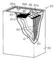
- the secondary battery 80 includes an electrode assembly 83 having a plurality of alternately stacked positive electrodes 81 and a plurality of negative electrodes 82, and a case 84 for housing the electrode assembly 83.
- the positive electrode 81 and the negative electrode 82 are insulated from each other.
- Each of the positive electrode 81 and the negative electrode 82 has a metal foil and an active material disposed on both sides of the metal foil.
- a positive electrode tab 81 a is provided on one side of each positive electrode 81.
- a negative electrode tab 82 a is provided on one side of each negative electrode 82.
- the secondary battery 80 further includes a positive electrode conductive member 85 joined to the plurality of positive electrode tabs 81 a and a negative electrode conductive member 86 joined to the plurality of negative electrode tabs 82 a.
- the lid member 84 a of the case 84 includes an injection hole 84 b for injecting the electrolytic solution into the case 84.
- the electrolytic solution is injected into the case from the injection hole, and the electrolytic solution is impregnated with the active material in the case, but it takes a lot of time to impregnate the active solution with the electrolytic solution. It is done.
- an embodiment of the power storage device is an electrode assembly having a plurality of first electrodes and a plurality of second electrodes, and the first electrode and the second electrode are stacked.
- An electrode assembly comprising: alternately stacked in directions and insulated from each other, each of the first electrode and the second electrode comprising a metal foil and an active material layer provided on at least one surface of the metal foil;
- a case for containing a liquid and the electrode assembly the case having a wall portion having a liquid injection hole for the electrolyte, the electrode assembly and the case insulated, and disposed in the case And an insulating member.
- the first tab group and the second tab group are spaced apart from each other in a direction orthogonal to the stacking direction along the opposing surface of the electrode assembly, and the first tab group and the second tab group Each is bent so that the first side faces the opposite side of the electrode assembly and the second side faces the wall of the case.
- the insulating member opens the entire facing surface of the electrode assembly to the outside of the insulating member.
- the liquid injection hole is sandwiched by the area of the wall where the first tab group and the second tab group are projected by viewing the wall in a direction orthogonal to the opposing surface of the electrode assembly. It is placed in position.
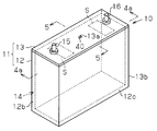
- FIG. 2 is a perspective view showing the appearance of the secondary battery of FIG. 1;
- 4A is a cross-sectional view taken along line 4a-4a of FIG. 2, and
- FIG. 4B is an enlarged cross-sectional view showing a curved surface portion in the vicinity of the bottom plate of the case.
- 5 is a cross-sectional view taken along line 5-5 of FIG.
- Sectional drawing which shows a secondary battery when the electrolyte solution is inject
- the perspective view which shows another example of an insulation member. The figure which shows background art.
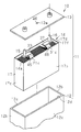
- the secondary battery 10 includes an electrode assembly 14 as a charge / discharge element, an electrolyte 18 as an electrolyte, an electrode assembly 14 and an electrolyte 18 And a case 11 for containing.
- the case 11 has a bottomed rectangular main body member 12 and a rectangular flat lid member 13.
- the lid member 13 and the main member 12 are welded by laser welding.
- the main body member 12 has a rectangular bottom plate 12a, short side walls 12b erected from a pair of opposed short side edges of the bottom plate 12a, and long side walls 12c erected from a pair of opposed long side edges of the bottom plate 12a.
- the main body member 12 has an insertion opening 12 d for inserting the electrode assembly 14.
- an inner corner portion formed by the short side walls 12b and the bottom plate 12a is a curved surface portion R having an arc-shaped cross section.
- the main body member 12 and the lid member 13 are both made of metal (for example, stainless steel or aluminum), and the lid member 13 closes the insertion port 12 d.
- the secondary battery 10 of the present embodiment is a rectangular battery whose appearance is a square shape, and is a lithium ion battery.
- the positive electrode terminal 15 and the negative electrode terminal 16 for extracting electricity from the electrode assembly 14 are electrically connected to the electrode assembly 14.
- the positive electrode terminal 15 and the negative electrode terminal 16 penetrate the lid member 13 and protrude outside the case 11.
- the electrode assembly 14 is configured by alternately laminating a plurality of positive electrode sheets 21 as a first electrode and a plurality of negative electrode sheets 31 as a second electrode.
- the direction in which the positive electrode sheet 21 and the negative electrode sheet 31 are stacked is referred to as a stacking direction.
- the separator 19 which insulates both from each other is arrange
- the positive electrode sheet 21 has a rectangular positive electrode metal foil (in the embodiment, an aluminum foil) 21 a and a positive electrode active material layer 21 b applied on both sides of the positive electrode metal foil 21 a.
- the negative electrode sheet 31 has a rectangular negative electrode metal foil (a copper foil in the present embodiment) 31 a and a negative electrode active material layer 31 b applied on both sides of the negative electrode metal foil 31 a.
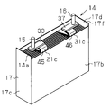
- the electrode assembly 14 has a first surface 14 a formed by gathering one side of the positive electrode sheet 21 and one side of the negative electrode sheet 31, that is, an opposing surface facing the lid member 13.
- the positive electrode tab group 45 protrudes from the first surface 14 a.
- the positive electrode tab group 45 has a first side and a second side opposite to the first side.
- the positive electrode tab group 45 is bent so that the first side faces the first side 14 a of the electrode assembly 14 and the second side faces the lid member 13.
- the positive electrode conductive member 33 is connected to the second side surface of the positive electrode tab group 45, and the positive electrode terminal 15 is connected to the positive electrode conductive member 33.
- All the negative electrode current collection tabs 31 c are gathered near the first end of the electrode assembly 14 to form the negative electrode tab group 46, and all the negative electrode current collection tabs 31 c are directed to the second end of the electrode assembly 14 It has been folded back.
- the negative electrode tab group 46 protrudes from the first surface 14 a of the electrode assembly 14.
- the negative electrode tab group 46 has a first side surface and a second side surface opposite to the first side surface.
- the negative electrode tab group 46 is bent so that the first side faces the first face 14 a of the electrode assembly 14 and the second side faces the lid member 13.
- the negative electrode conductive member 37 is connected to the second side surface of the negative electrode tab group 46, and the negative electrode terminal 16 is connected to the negative electrode conductive member 37.
- the positive electrode current collection tab 21c and the negative electrode current collection tab 31c are collected so as not to contact each other, and the positive electrode tab group 45 and the negative electrode tab group 46 are separated in the direction orthogonal to the stacking direction and along the first surface 14a. Are arranged.
- an insulating member 17 made of resin and having a square box shape is accommodated inside the main body member 12.
- the electrode assembly 14 has a second surface 14b opposite to the first surface 14a.
- the insulating member 17 includes a bottom covering portion 17 a that insulates between the second surface 14 b of the electrode assembly 14 and the bottom plate 12 a of the case 11. Further, the electrode assembly 14 has two surfaces orthogonal to the first surface 14 a and parallel to the stacking direction, that is, two side surfaces 14 d.
- the insulating member 17 includes second covering portions 17 c disposed between the side surfaces 14 d of the electrode assembly 14 and the short side walls 12 b of the main body member 12.
- the insulating member 17 is placed on the bottom plate 12a so that the bottom side covering portion 17a is not placed on the both curved surface portions R, and each second covering portion 17c is provided.
- a gap F is formed between the outer surface of and the corresponding short side wall 12b.
- the electrode assembly 14 has two surfaces orthogonal to the first surface 14a and orthogonal to the stacking direction, that is, two end surfaces 14c.
- the end surfaces 14 c are surfaces located at both ends of the electrode assembly 14 in the stacking direction.
- the insulating member 17 is provided with a first covering portion 17 b which insulates between each end face 14 c of the electrode assembly 14 and each long side wall 12 c of the main body member 12. Furthermore, the insulating member 17 has an opening 17 d for inserting the electrode assembly 14, and the entire first surface 14 a of the electrode assembly 14 is open to the outside of the insulating member 17.
- the opening end 17f of the insulating member 17 is located above the first surface 14a in the direction in which the positive electrode current collection tab 21c and the negative electrode current collection tab 31c protrude from the first surface 14a. That is, the first covering portion 17 b and the second covering portion 17 c of the insulating member 17 extend beyond the first surface 14 a in the direction orthogonal to the first surface 14 a of the electrode assembly 14, and the opening end 17 f of the insulating member 17
- the first surface 14a is located at a lower position than that.
- the outer surfaces of both first covering portions 17b are hardly separated from the opposing long side wall 12c.
- the cover member 13 is provided with the liquid injection hole 13a penetrated in the thickness direction. Therefore, in the present embodiment, the lid member 13 constitutes the wall of the case 11 having the liquid injection hole 13a.
- the two regions S surrounded by dotted lines are lids on which the positive electrode tab group 45 and the negative electrode tab group 46 are projected when the cover member 13 is viewed from the direction orthogonal to the first surface 14 a of the electrode assembly 14.
- the liquid injection hole 13 a is provided at a position between the two regions S.
- the liquid injection hole 13a is disposed at a position not facing the positive electrode tab group 45 and the negative electrode tab group 46, and the liquid injection hole 13a is a first surface 14a of the electrode assembly 14. It is directly opposed to.
- the liquid injection hole 13 a is disposed at the center of the lid 13 in the longitudinal direction and at the center of the lid 13 in the lateral direction. That is, the liquid injection holes 13a are disposed at positions equidistant from the two regions S. Further, the liquid injection hole 13 a is sealed by the sealing member 40, and the leakage of the gas and the electrolytic solution 18 from the inside of the case 11 is prevented.
- the electrode assembly 14 is covered with the insulating member 17, and the electrode assembly 14 is inserted into the main body member 12 together with the insulating member 17 from the bottom covering portion 17 a through the insertion port 12 d.
- the lid member 13 is joined to the opening end of the main body member 12 and the insertion port 12 d is closed by the lid member 13 and the case 11 is formed.
- the electrolytic solution 18 is injected into the case 11 from the injection hole 13a. Then, when the electrolytic solution 18 is injected from the liquid injection hole 13a, the liquid injection hole 13a is sealed by the sealing member 40, and the secondary battery 10 is assembled.
- the electrolytic solution 18 is poured into a region of the first surface 14 a of the electrode assembly 14 sandwiched between the positive electrode tab group 45 and the negative electrode tab group 46. Then, a part of the electrolytic solution 18 flows in all directions including the stacking direction along the first surface 14 a of the electrode assembly 14. At this time, when the electrolytic solution 18 contacts the positive electrode tab group 45 and the negative electrode tab group 46, the flow of the electrolytic solution 18 toward the short side walls 12b becomes gentle. Further, the electrolytic solution 18 is temporarily blocked by the open end 17 f side of the insulating member 17 on both sides in the stacking direction. As a result, on the first surface 14 a of the electrode assembly 14, the electrolytic solution 18 temporarily stays between the positive electrode tab group 45 and the negative electrode tab group 46.
- the secondary battery 10 is completed.
- the positive electrode tab group 45 and the negative electrode tab group 46 allow the electrolyte 18 poured from the liquid injection hole 13 a to be temporarily retained on the first surface 14 a of the electrode assembly 14. Therefore, in the case where the electrolytic solution 18 can be impregnated with the active material from both the first surface 14 a and the second surface 14 b of the electrode assembly 14, and is impregnated only by the capillary phenomenon against gravity from the second surface 14 b alone. Compared to the above, the time required to impregnate the active material with the electrolytic solution 18 can be shortened.
- the insulating member 17 has the opening 17 d and opens the entire first surface 14 a of the electrode assembly 14 to the outside of the insulating member 17. For this reason, the electrolytic solution 18 poured into the case 11 from the liquid injection hole 13a can be reliably supplied onto the first surface 14a of the electrode assembly 14, and can be made to stay on the first surface 14a.
- each second covering portion of the insulating member 17 A clearance F is formed between the outer surface of 17 c and the inner surface of each short side wall 12 b.
- the electrolytic solution 18 easily flows into the space F, and when the electrolytic solution 18 flows into the space F, the electrolytic solution 18 hardly stays on the first surface 14 a of the electrode assembly 14. However, by causing the electrolytic solution 18 to flow gently by the positive electrode tab group 45 and the negative electrode tab group 46, even if the gap F is formed, the electrolytic solution 18 is retained on the first surface 14 a of the electrode assembly 14 be able to.
- All the positive electrode sheets 21 are provided with the positive electrode current collection tab 21c, and the positive electrode tab group 45 is formed using all the positive electrode current collection tabs 21c.
- all the negative electrode sheets 31 are provided with the negative electrode current collection tab 31c, and the negative electrode tab group 46 is formed using all the negative electrode current collection tabs 31c. Therefore, the gap between the positive electrode current collecting tabs 21c in the positive electrode tab group 45 and the gap between the negative electrode current collecting tabs 31c in the negative electrode tab group 46 can be narrowed, so that the electrolyte 18 flows gently and reliably. can do.
- the liquid injection holes 13a are arranged at equal distances from the two regions S of the lid 13 onto which the positive electrode tab group 45 and the negative electrode tab group 46 are projected. Therefore, the electrolytic solution 18 can be poured to an intermediate position between the positive electrode tab group 45 and the negative electrode tab group 46, and the electrolytic solution 18 can be made less likely to be uneven on the first surface 14a. Therefore, the electrolytic solution 18 can be impregnated substantially uniformly in all directions from the first surface 14 a of the electrode assembly 14.
- the liquid injection hole 13a is at a position deviated from the center in the longitudinal direction and the short direction of the lid member 13 if the lid member 13 is sandwiched by the region S where the positive electrode tab group 45 and the negative electrode tab group 46 are projected. It may be arranged.
- the second covering portion 17 c of the insulating member 17 protrudes from the first surface 14 a of the electrode assembly 14 in the direction in which the tabs 21 c and 31 c protrude (a direction orthogonal to the first surface 14 a May be extended to According to this structure, the second covering portion 17c can reliably prevent the flow of the electrolytic solution 18 into the gap F between the outer surface of each of the second covering portions 17c and the inner surface of each of the short side walls 12b.
- the electrolyte 18 can be retained on the first surface 14 a of the electrode assembly 14.
- the first covering portion 17b may be formed of each of the tabs 21c and 31c from the first surface 14a. It may be extended in the projecting direction (the direction orthogonal to the first surface 14a).
- the opening end 17f of the insulating member 17 is located above the first surface 14a along the direction in which the positive electrode current collection tab 21c and the negative electrode current collection tab 31c protrude from the first surface 14a (the direction orthogonal to the first surface 14a). Instead of being located, it may be located on the same plane as the first surface 14a.
- the liquid injection hole 13a is provided in the lid member 13 as the wall portion of the case 11, but the liquid injection hole is the bottom plate 12a, the short side wall 12b, or the long side wall 12c in the main body member 12 as the wall portion of the case 11. It may be provided in In this case, the way of inserting the electrode assembly 14 into the body member 12 is adjusted such that the first surface 14a of the electrode assembly 14 faces the bottom plate 12a, the short side wall 12b, or the long side wall 12c.
- the number of positive electrode sheets 21 and negative electrode sheets 31 constituting the electrode assembly 14 may be changed as appropriate.
- the positive electrode active material layer 21b may be provided only on one side of the positive electrode metal foil 21a, and the negative electrode active material layer 31b may be provided only on one side of the negative electrode metal foil 31a.
- the power storage device may be a nickel hydrogen secondary battery.
Landscapes
- Chemical & Material Sciences (AREA)
- Chemical Kinetics & Catalysis (AREA)
- Electrochemistry (AREA)
- General Chemical & Material Sciences (AREA)
- Engineering & Computer Science (AREA)
- Manufacturing & Machinery (AREA)
- Inorganic Chemistry (AREA)
- Secondary Cells (AREA)
- Connection Of Batteries Or Terminals (AREA)
- Cell Separators (AREA)
- Filling, Topping-Up Batteries (AREA)
- Sealing Battery Cases Or Jackets (AREA)
Abstract
Description
Claims (5)
- 複数の第1電極と複数の第2電極とを有する電極組立体であって、前記第1電極と前記第2電極とは積層方向に交互に積層されるとともに互いから絶縁され、前記第1電極及び前記第2電極の各々は金属箔と同金属箔の少なくとも一面に設けられた活物質層とを有する、電極組立体と、
電解液と前記電極組立体とを収容するケースであって、前記電解液の注液孔を有する壁部を備えたケースと、
前記電極組立体と前記ケースとを絶縁するとともに、前記ケース内に配置される絶縁部材と、を備え、
前記電極組立体は前記ケースの壁部に対向する対向面を有し、前記複数の第1電極のうちの少なくとも一部は同第1電極から電気を取り出すために第1電極の一辺から突出する第1タブを有し、前記複数の第2電極のうちの少なくとも一部は同第2電極から電気を取り出すために第2電極の一辺から突出する第2タブを有し、前記第1タブは前記電極組立体の前記対向面において第1タブ群を形成するように前記積層方向に集められており、前記第2タブは前記電極組立体の前記対向面において第2タブ群を形成するように前記積層方向に集められており、前記第1タブ群及び前記第2タブ群の各々は互いに反対側の第1側面及び第2側面を有し、
前記第1タブ群と前記第2タブ群とは、前記電極組立体の対向面に沿って前記積層方向に直交する方向に互いに離間しており、前記第1タブ群及び前記第2タブ群の各々は前記第1側面が前記電極組立体の前記対向面に対向するとともに前記第2側面が前記ケースの前記壁部に対向する状態に曲げられており、
前記絶縁部材は、前記電極組立体の前記対向面全体を前記絶縁部材外に開放させ、
前記注液孔は、前記電極組立体の前記対向面に直交する方向から前記壁部を見て前記第1タブ群と前記第2タブ群とが投影される前記壁部の領域に挟まれた位置に配置されている蓄電装置。 - 全ての前記第1電極が前記第1タブを有しており、前記第1タブ群は全ての前記第1タブを含み、全ての前記第2電極が前記第2タブを有しており、前記第2タブ群は全ての前記第2タブを含む請求項1に記載の蓄電装置。
- 前記絶縁部材は、前記対向面に直交する前記電極組立体の複数の面をそれぞれ覆う複数の被覆部を有し、
前記被覆部の少なくとも1つは、前記電極組立体の前記対向面に直交する方向において同対向面を超えて延びている請求項1又は請求項2に記載の蓄電装置。 - 前記電極組立体は、前記対向面に直交するとともに前記積層方向における電極組立体の両端面を含まない2つの面を有し、
前記絶縁部材は、前記電極組立体の前記2つの面の少なくとも1つを覆う被覆部を有し、
前記被覆部は、前記電極組立体の前記対向面に直交する方向において同対向面を超えて延びている請求項1又は請求項2に記載の蓄電装置。 - 前記蓄電装置は二次電池である請求項1~請求項4のうちいずれか一項に記載の蓄電装置。
Priority Applications (3)
| Application Number | Priority Date | Filing Date | Title |
|---|---|---|---|
| US14/779,740 US9755219B2 (en) | 2013-03-29 | 2014-02-28 | Electrical storage apparatus |
| DE112014001743.4T DE112014001743T5 (de) | 2013-03-29 | 2014-02-28 | Elektrospeichervorrichtung |
| CN201480017530.5A CN105122530B (zh) | 2013-03-29 | 2014-02-28 | 蓄电装置 |
Applications Claiming Priority (2)
| Application Number | Priority Date | Filing Date | Title |
|---|---|---|---|
| JP2013073816A JP5574003B1 (ja) | 2013-03-29 | 2013-03-29 | 蓄電装置 |
| JP2013-073816 | 2013-03-29 |
Publications (1)
| Publication Number | Publication Date |
|---|---|
| WO2014156474A1 true WO2014156474A1 (ja) | 2014-10-02 |
Family
ID=51578979
Family Applications (1)
| Application Number | Title | Priority Date | Filing Date |
|---|---|---|---|
| PCT/JP2014/055127 Ceased WO2014156474A1 (ja) | 2013-03-29 | 2014-02-28 | 蓄電装置 |
Country Status (5)
| Country | Link |
|---|---|
| US (1) | US9755219B2 (ja) |
| JP (1) | JP5574003B1 (ja) |
| CN (1) | CN105122530B (ja) |
| DE (1) | DE112014001743T5 (ja) |
| WO (1) | WO2014156474A1 (ja) |
Cited By (1)
| Publication number | Priority date | Publication date | Assignee | Title |
|---|---|---|---|---|
| CN108028350A (zh) * | 2015-09-18 | 2018-05-11 | 锂能源和电力有限责任两合公司 | 电化学能量储存装置 |
Families Citing this family (8)
| Publication number | Priority date | Publication date | Assignee | Title |
|---|---|---|---|---|
| JP6506575B2 (ja) * | 2015-03-13 | 2019-04-24 | マクセルホールディングス株式会社 | 電池 |
| US12191499B2 (en) | 2017-02-27 | 2025-01-07 | Sanyo Electric Co., Ltd. | Rectangular secondary battery and method of manufacturing the same |
| JP6669303B2 (ja) * | 2017-02-28 | 2020-03-18 | 株式会社豊田自動織機 | 蓄電装置の製造方法 |
| JP7055648B2 (ja) * | 2018-01-26 | 2022-04-18 | 三洋電機株式会社 | 蓄電装置 |
| EP4044354A4 (en) * | 2019-10-10 | 2024-02-28 | Murata Manufacturing Co., Ltd. | SECONDARY BATTERY |
| CN121282315A (zh) * | 2021-02-10 | 2026-01-06 | 宁德时代新能源科技股份有限公司 | 电池单体、电池、用电设备及电池单体的制造设备和方法 |
| CN115101822A (zh) * | 2022-06-13 | 2022-09-23 | 宁德新能源科技有限公司 | 电化学装置及用电设备 |
| CN117438749A (zh) * | 2022-07-14 | 2024-01-23 | 宁德时代新能源科技股份有限公司 | 电池单体、电池及用电装置 |
Citations (5)
| Publication number | Priority date | Publication date | Assignee | Title |
|---|---|---|---|---|
| JP2001110692A (ja) * | 1999-10-08 | 2001-04-20 | Kansai Coke & Chem Co Ltd | 電気二重層コンデンサ用電極積層体、並びに該電気二重層コンデンサ用電極積層体の不純物除去装置及び電解液含浸装置 |
| JP2002270218A (ja) * | 2001-03-12 | 2002-09-20 | Shin Kobe Electric Mach Co Ltd | 小形制御弁式鉛蓄電池及びその製造方法 |
| JP2012014935A (ja) * | 2010-06-30 | 2012-01-19 | Mitsubishi Heavy Ind Ltd | 電池 |
| WO2012140716A1 (ja) * | 2011-04-11 | 2012-10-18 | 三菱重工業株式会社 | 電解液注液装置 |
| JP2014026867A (ja) * | 2012-07-27 | 2014-02-06 | Toyota Industries Corp | 蓄電装置 |
Family Cites Families (9)
| Publication number | Priority date | Publication date | Assignee | Title |
|---|---|---|---|---|
| JP2003229112A (ja) | 2002-02-04 | 2003-08-15 | Mitsubishi Heavy Ind Ltd | 非水電解質2次電池及び非水電解質2次電池の製造方法 |
| JP4296522B2 (ja) * | 2007-08-23 | 2009-07-15 | トヨタ自動車株式会社 | 電池およびその製造方法 |
| CN102576826B (zh) * | 2009-09-24 | 2014-11-19 | 株式会社Lg化学 | 具有切口凹槽的矩形可充电电池 |
| KR101036089B1 (ko) | 2010-01-27 | 2011-05-19 | 에스비리모티브 주식회사 | 절연 백을 갖는 이차전지 |
| KR101116577B1 (ko) * | 2010-02-03 | 2012-02-24 | 에스비리모티브 주식회사 | 이차전지 및 그 제조 방법 |
| US20110206976A1 (en) * | 2010-02-19 | 2011-08-25 | Kyung-Mo Yoo | Electrode assembly and secondary battery using the same |
| CN102055007A (zh) * | 2010-12-13 | 2011-05-11 | 湖南科力远新能源股份有限公司 | 具有特殊结构的电池及其制作方法 |
| KR101222309B1 (ko) * | 2010-12-29 | 2013-01-15 | 로베르트 보쉬 게엠베하 | 이차전지 |
| CN105261798B (zh) * | 2015-11-07 | 2018-05-01 | 合肥国轩高科动力能源有限公司 | 一种适用于装配方形锂电池极组的装配装置及装配方法 |
-
2013
- 2013-03-29 JP JP2013073816A patent/JP5574003B1/ja active Active
-
2014
- 2014-02-28 CN CN201480017530.5A patent/CN105122530B/zh active Active
- 2014-02-28 DE DE112014001743.4T patent/DE112014001743T5/de not_active Ceased
- 2014-02-28 WO PCT/JP2014/055127 patent/WO2014156474A1/ja not_active Ceased
- 2014-02-28 US US14/779,740 patent/US9755219B2/en active Active
Patent Citations (5)
| Publication number | Priority date | Publication date | Assignee | Title |
|---|---|---|---|---|
| JP2001110692A (ja) * | 1999-10-08 | 2001-04-20 | Kansai Coke & Chem Co Ltd | 電気二重層コンデンサ用電極積層体、並びに該電気二重層コンデンサ用電極積層体の不純物除去装置及び電解液含浸装置 |
| JP2002270218A (ja) * | 2001-03-12 | 2002-09-20 | Shin Kobe Electric Mach Co Ltd | 小形制御弁式鉛蓄電池及びその製造方法 |
| JP2012014935A (ja) * | 2010-06-30 | 2012-01-19 | Mitsubishi Heavy Ind Ltd | 電池 |
| WO2012140716A1 (ja) * | 2011-04-11 | 2012-10-18 | 三菱重工業株式会社 | 電解液注液装置 |
| JP2014026867A (ja) * | 2012-07-27 | 2014-02-06 | Toyota Industries Corp | 蓄電装置 |
Cited By (1)
| Publication number | Priority date | Publication date | Assignee | Title |
|---|---|---|---|---|
| CN108028350A (zh) * | 2015-09-18 | 2018-05-11 | 锂能源和电力有限责任两合公司 | 电化学能量储存装置 |
Also Published As
| Publication number | Publication date |
|---|---|
| US9755219B2 (en) | 2017-09-05 |
| US20160056445A1 (en) | 2016-02-25 |
| CN105122530A (zh) | 2015-12-02 |
| JP2014199727A (ja) | 2014-10-23 |
| CN105122530B (zh) | 2017-05-17 |
| JP5574003B1 (ja) | 2014-08-20 |
| DE112014001743T5 (de) | 2015-12-17 |
Similar Documents
| Publication | Publication Date | Title |
|---|---|---|
| US9767965B2 (en) | Electric storage device, and electric storage apparatus | |
| JP5574003B1 (ja) | 蓄電装置 | |
| JP6226413B2 (ja) | 蓄電素子及び蓋板の製造方法 | |
| JP6158474B2 (ja) | 二次電池 | |
| CN104185912B (zh) | 蓄电装置 | |
| CN107431153B (zh) | 蓄电元件 | |
| JP5858074B2 (ja) | 蓄電装置 | |
| JP5742869B2 (ja) | 蓄電装置 | |
| US10991985B2 (en) | Secondary battery | |
| WO2015098955A1 (ja) | 蓄電装置 | |
| CN105870389A (zh) | 二次电池 | |
| JP2015032386A (ja) | 蓄電装置 | |
| JP2015185470A (ja) | 蓄電素子 | |
| CN108028350A (zh) | 电化学能量储存装置 | |
| JP6722545B2 (ja) | 絶縁部材と二次電池 | |
| JP2018206758A (ja) | 蓄電装置及び蓄電装置の製造方法 | |
| JP2019121433A (ja) | 蓄電装置 | |
| CN107834012A (zh) | 层叠型电池 | |
| JP2021026983A (ja) | 蓄電装置 | |
| JP2016021281A (ja) | 蓄電装置 | |
| JP2018139215A (ja) | 蓄電素子 | |
| JP2014082070A (ja) | 蓄電装置 | |
| US20260074298A1 (en) | Electricity storage device | |
| JP2019175689A (ja) | 蓄電装置 | |
| JP2020053207A (ja) | 蓄電素子 |
Legal Events
| Date | Code | Title | Description |
|---|---|---|---|
| 121 | Ep: the epo has been informed by wipo that ep was designated in this application |
Ref document number: 14773573 Country of ref document: EP Kind code of ref document: A1 |
|
| WWE | Wipo information: entry into national phase |
Ref document number: 14779740 Country of ref document: US |
|
| WWE | Wipo information: entry into national phase |
Ref document number: 1120140017434 Country of ref document: DE Ref document number: 112014001743 Country of ref document: DE |
|
| 122 | Ep: pct application non-entry in european phase |
Ref document number: 14773573 Country of ref document: EP Kind code of ref document: A1 |