WO2014156468A1 - 制振構造、および、それに用いる制振シート材 - Google Patents
制振構造、および、それに用いる制振シート材 Download PDFInfo
- Publication number
- WO2014156468A1 WO2014156468A1 PCT/JP2014/055068 JP2014055068W WO2014156468A1 WO 2014156468 A1 WO2014156468 A1 WO 2014156468A1 JP 2014055068 W JP2014055068 W JP 2014055068W WO 2014156468 A1 WO2014156468 A1 WO 2014156468A1
- Authority
- WO
- WIPO (PCT)
- Prior art keywords
- vibration
- sheet material
- damping
- vibrating member
- vibration member
- Prior art date
- Legal status (The legal status is an assumption and is not a legal conclusion. Google has not performed a legal analysis and makes no representation as to the accuracy of the status listed.)
- Ceased
Links
Images
Classifications
-
- B—PERFORMING OPERATIONS; TRANSPORTING
- B32—LAYERED PRODUCTS
- B32B—LAYERED PRODUCTS, i.e. PRODUCTS BUILT-UP OF STRATA OF FLAT OR NON-FLAT, e.g. CELLULAR OR HONEYCOMB, FORM
- B32B25/00—Layered products comprising a layer of natural or synthetic rubber
- B32B25/14—Layered products comprising a layer of natural or synthetic rubber comprising synthetic rubber copolymers
-
- B—PERFORMING OPERATIONS; TRANSPORTING
- B32—LAYERED PRODUCTS
- B32B—LAYERED PRODUCTS, i.e. PRODUCTS BUILT-UP OF STRATA OF FLAT OR NON-FLAT, e.g. CELLULAR OR HONEYCOMB, FORM
- B32B25/00—Layered products comprising a layer of natural or synthetic rubber
- B32B25/04—Layered products comprising a layer of natural or synthetic rubber comprising rubber as the main or only constituent of a layer, which is next to another layer of the same or of a different material
-
- C—CHEMISTRY; METALLURGY
- C08—ORGANIC MACROMOLECULAR COMPOUNDS; THEIR PREPARATION OR CHEMICAL WORKING-UP; COMPOSITIONS BASED THEREON
- C08J—WORKING-UP; GENERAL PROCESSES OF COMPOUNDING; AFTER-TREATMENT NOT COVERED BY SUBCLASSES C08B, C08C, C08F, C08G or C08H
- C08J5/00—Manufacture of articles or shaped materials containing macromolecular substances
- C08J5/18—Manufacture of films or sheets
-
- C—CHEMISTRY; METALLURGY
- C08—ORGANIC MACROMOLECULAR COMPOUNDS; THEIR PREPARATION OR CHEMICAL WORKING-UP; COMPOSITIONS BASED THEREON
- C08L—COMPOSITIONS OF MACROMOLECULAR COMPOUNDS
- C08L53/00—Compositions of block copolymers containing at least one sequence of a polymer obtained by reactions only involving carbon-to-carbon unsaturated bonds; Compositions of derivatives of such polymers
- C08L53/02—Compositions of block copolymers containing at least one sequence of a polymer obtained by reactions only involving carbon-to-carbon unsaturated bonds; Compositions of derivatives of such polymers of vinyl-aromatic monomers and conjugated dienes
- C08L53/025—Compositions of block copolymers containing at least one sequence of a polymer obtained by reactions only involving carbon-to-carbon unsaturated bonds; Compositions of derivatives of such polymers of vinyl-aromatic monomers and conjugated dienes modified
-
- B—PERFORMING OPERATIONS; TRANSPORTING
- B32—LAYERED PRODUCTS
- B32B—LAYERED PRODUCTS, i.e. PRODUCTS BUILT-UP OF STRATA OF FLAT OR NON-FLAT, e.g. CELLULAR OR HONEYCOMB, FORM
- B32B2307/00—Properties of the layers or laminate
- B32B2307/50—Properties of the layers or laminate having particular mechanical properties
- B32B2307/51—Elastic
-
- B—PERFORMING OPERATIONS; TRANSPORTING
- B32—LAYERED PRODUCTS
- B32B—LAYERED PRODUCTS, i.e. PRODUCTS BUILT-UP OF STRATA OF FLAT OR NON-FLAT, e.g. CELLULAR OR HONEYCOMB, FORM
- B32B2457/00—Electrical equipment
-
- C—CHEMISTRY; METALLURGY
- C08—ORGANIC MACROMOLECULAR COMPOUNDS; THEIR PREPARATION OR CHEMICAL WORKING-UP; COMPOSITIONS BASED THEREON
- C08J—WORKING-UP; GENERAL PROCESSES OF COMPOUNDING; AFTER-TREATMENT NOT COVERED BY SUBCLASSES C08B, C08C, C08F, C08G or C08H
- C08J2309/00—Characterised by the use of homopolymers or copolymers of conjugated diene hydrocarbons
- C08J2309/06—Copolymers with styrene
-
- C—CHEMISTRY; METALLURGY
- C08—ORGANIC MACROMOLECULAR COMPOUNDS; THEIR PREPARATION OR CHEMICAL WORKING-UP; COMPOSITIONS BASED THEREON
- C08J—WORKING-UP; GENERAL PROCESSES OF COMPOUNDING; AFTER-TREATMENT NOT COVERED BY SUBCLASSES C08B, C08C, C08F, C08G or C08H
- C08J2409/00—Characterised by the use of homopolymers or copolymers of conjugated diene hydrocarbons
- C08J2409/06—Copolymers with styrene
-
- C—CHEMISTRY; METALLURGY
- C08—ORGANIC MACROMOLECULAR COMPOUNDS; THEIR PREPARATION OR CHEMICAL WORKING-UP; COMPOSITIONS BASED THEREON
- C08K—Use of inorganic or non-macromolecular organic substances as compounding ingredients
- C08K5/00—Use of organic ingredients
- C08K5/04—Oxygen-containing compounds
- C08K5/14—Peroxides
Definitions
- the present invention relates to a vibration damping structure, and a vibration damping sheet material used therefor, and more specifically, a vibration damping structure configured to reduce vibration generated in a part constituting a casing or a part such as an electric / electronic device, and
- the present invention relates to a vibration damping sheet material used therefor.
- a damping steel plate that suppresses vibration of the thin plate portion itself is also known as a method of damping the thin plate portion of the housing or component (see, for example, Patent Document 2).
- the vibration-damping rigid plate has a problem that the workability is poor, the degree of freedom in housing design cannot be secured, and the size reduction cannot be sufficiently achieved.
- An object of the present invention is to provide a vibration damping structure having good vibration damping properties and a vibration damping sheet material used for the vibration damping sheet material, which is less likely to be deformed or drooped and is reduced in size. .
- the elastic modulus and the vibration member is 1.0 ⁇ 10 10 Pa or more
- the non-vibrating member to which the elastic modulus is 1.0 ⁇ 10 10 Pa or more, generated in the vibration member vibrating Including a styrene copolymer rubber which is interposed between the vibrating member and the non-vibrating member, has a glass transition point of ⁇ 25 ° C. or higher, and is crosslinked.
- the styrene copolymer rubber is crosslinked using an organic peroxide.
- the styrene copolymer rubber is selected from the group consisting of a styrene butadiene random copolymer, a styrene butadiene block copolymer, a styrene isoprene block copolymer, and hydrogenated products thereof. It is preferable that it is at least one kind.
- the vibration damping sheet material of the present invention is a vibration damping sheet material used for damping a vibration member having an elastic modulus of 1.0 ⁇ 10 10 Pa or more, and has a glass transition point of ⁇ 25 ° C. or more. Yes, it is characterized by containing a crosslinked styrene copolymer rubber.
- the vibration damping sheet material used in the reinforcing structure of the present invention contains a styrene copolymer rubber having a glass transition point of ⁇ 25 ° C. or higher and crosslinked. Therefore, the vibration damping sheet material is not easily deformed or drooped even in a high temperature environment.
- the elastic member has a modulus of elasticity of 1.0 ⁇ 10 10 Pa or more in the path through which vibration generated in the vibrating member is transmitted to the non-vibrating member;
- the vibration-damping sheet material of the present invention is interposed between the non-vibrating member that is 0 ⁇ 10 10 Pa or more. Therefore, the vibration member can be sufficiently damped while reducing the size of the reinforcing structure.
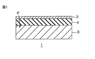
- FIG. 1 is a side sectional view of an embodiment of the vibration damping structure of the present invention.
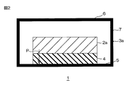
- FIG. 2 is a side sectional view of another embodiment of the vibration damping structure of the present invention (a structure in which a vibration member is accommodated inside a non-vibration member).
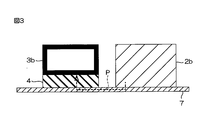
- FIG. 3 is a side cross-sectional view of an embodiment of a vibration damping structure using the vibration damping member of the present invention (a structure in which a vibration member and a vibration damping sheet material are arranged at an interval).
- the vibration damping structure 1 is interposed between the vibration member 2, the non-vibration member 3 that is disposed to face the vibration member 2 with a space therebetween, and the vibration member 2 and the non-vibration member 3.
- the sheet material 4 is provided.
- the path P through which the vibration generated in the vibration member 2 is transmitted to the non-vibration member 3 extends from the vibration member 2 to the non-vibration member 3 along the opposing direction of the vibration member 2 and the non-vibration member 3. Formed to head toward.
- the vibration member 2 has, for example, a substantially rectangular shape in plan view and is formed in a flat plate.
- the elastic modulus of the vibrating member 2 is 1.0 ⁇ 10 10 Pa or more, preferably 1.5 ⁇ 10 10 Pa or more. For example, 6.0 ⁇ 10 11 Pa or less, preferably 5.0 ⁇ 10 11 Pa or less.
- the elastic modulus is measured by a tensile test (JIS Z 2280).
- Examples of the material constituting the vibration member 2 include metals such as aluminum, iron, copper, titanium, and nickel, metal oxides such as alumina, and curable resins such as epoxy resins.
- metals such as aluminum, iron, copper, titanium, and nickel
- metal oxides such as alumina
- curable resins such as epoxy resins.
- a metal more preferably aluminum is used.
- the thickness of the vibration member 2 is, for example, 0.2 mm or more, preferably 0.5 mm or more, and, for example, 5.0 mm or less, preferably 3.5 mm or less.
- the non-vibrating member 3 is opposed to the vibrating member 2 on the lower side.
- the non-vibrating member 3 has, for example, a substantially rectangular shape in plan view, is formed in a flat plate, and is disposed so as to overlap with the vibrating member 2 when projected in the thickness direction.
- the elastic modulus of the non-vibrating member 3 is 1.0 ⁇ 10 10 Pa or more, preferably 1.5 ⁇ 10 10 Pa or more, for example, 6.0 ⁇ 10 11 Pa or less, preferably 5. 0 ⁇ 10 11 Pa or less.
- the non-vibrating member 3 acts as a constraining layer having rigidity, and the vibrating member 2 can be satisfactorily damped via the sheet material 4.
- the material constituting the non-vibrating member 3 is the same material as that constituting the vibrating member 2.
- aluminum is used. If the non-vibrating member 3 is made of aluminum, good heat dissipation can be ensured when the damping structure 1 is an electric / electronic device.
- the thickness of the non-vibrating member 3 is, for example, 0.2 mm or more, preferably 0.5 mm or more, and, for example, 5.0 mm or less, preferably 3.5 mm or less.
- the sheet material 4 is interposed between the vibrating member 2 and the non-vibrating member 3 facing each other. Specifically, the sheet material 4 is formed between the vibrating member 2 and the non-vibrating member 3 such that one surface (upper surface) is in contact with the vibrating member 2 and the other surface (lower surface) is in contact with the non-vibrating member 3. Arranged between.
- the sheet material 4 has, for example, a substantially rectangular shape in plan view, is formed in a flat plate, and is formed so as to overlap the vibration member 2 and the non-vibration member 3 when projected in the thickness direction.
- the sheet material 4 is formed from a resin composition containing a styrene copolymer rubber.
- styrene copolymer rubber contained in the resin composition examples include styrene butadiene random copolymer (SBR), styrene butadiene block copolymer (SBS), styrene isoprene block copolymer (SIS), and hydrogenation thereof.
- SBR styrene butadiene random copolymer
- SBS styrene butadiene block copolymer
- SIS styrene isoprene block copolymer
- hydrogenation thereof hydrogenation thereof.
- SEBS, SEPS styrene butadiene random copolymer
- SEBS styrene butadiene block copolymer
- SIS styrene isoprene block copolymer
- hydrogenation thereof hydrogenation thereof.
- SEBS styrene butadiene random copolymer
- SBS styrene butadiene block copoly
- the styrene content of the styrene copolymer rubber is preferably 10% by mass or more, preferably 15% by mass or more, and for example, 80% by mass or less, preferably 70% by mass or less.
- the glass transition point of the sheet material 4 can be set to ⁇ 25 ° C. or more, and the vibration damping property is excellent.
- the Mooney viscosity of SBR is, for example, 30 to 80 (ML5 + 4, at 100 ° C.), preferably 40 to 70 (ML 5 + 4, at 100 ° C.).
- MFR melt flow rate
- styrene copolymer rubbers may be used alone or in combination of two or more.
- SBR and SIS are used in combination.
- SBR: SIS 90: 10 to 70:30, preferably 85:15 to 75:25.
- the resin composition preferably contains a crosslinking agent in addition to the styrene copolymer rubber.
- a crosslinking agent By containing a crosslinking agent, the styrene copolymer rubber can be crosslinked. Thereby, even when the sheet material 4 is heated to a high temperature, it is possible to make the sheet material 4 less likely to sag or deform.
- crosslinking agent examples include sulfur, sulfur compounds, selenium, magnesium oxide, lead monoxide, organic peroxides, polyamines, oximes, nitroso compounds, resins, and ammonium salts.
- a crosslinking agent may be used independently and can also be used together 2 or more types.
- organic peroxides are preferable from the viewpoint of preventing corrosion and providing good heat resistance.
- organic peroxide examples include dicumyl peroxide, dimethyldi (t-butylperoxy) hexane, dimethyldi (t-butylperoxy) hexyne, bis (t-butylperoxyisopropyl) benzene, 1,1-diter
- dicumyl peroxide dimethyldi (t-butylperoxy) hexane
- dimethyldi (t-butylperoxy) hexyne examples include bis (t-butylperoxyisopropyl) benzene, 1,1-diter
- tributyl peroxy-3,3,5-trimethylcyclohexane examples include tributyl peroxy-3,3,5-trimethylcyclohexane, tertiary butyl peroxyketone, and tertiary butyl peroxybenzoate).
- physical crosslinking agents Specifically, dicumyl peroxide (1 minute half-life temperature: 175 ° C.), dimethyldi (t-butylperoxy) hexane (1 minute half-life temperature: 180 ° C.), bis (t-butylperoxyisopropyl) benzene (1 minute half-life temperature: 175 ° C.). Particularly preferred is dicumyl peroxide.
- the blending ratio of the crosslinking agent is, for example, 0.1 parts by mass or more, preferably 0.5 parts by mass or more, and, for example, 10 parts by mass or less, preferably 100 parts by mass of styrene copolymer rubber. Is 5 parts by mass or less.
- the resin composition can contain a crosslinking accelerator as necessary together with the crosslinking agent.
- crosslinking agent accelerator examples include zinc oxide, disulfides, dithiocarbamic acids, thiazoles, guanidines, sulfenamides, thiurams, xanthogenic acids, aldehyde ammonias, aldehyde amines, and thioureas.
- crosslinking accelerators can be used alone or in combination of two or more.
- the blending ratio is, for example, 0.5 parts by mass or more, preferably 1 part by mass or more, and, for example, 20 parts by mass with respect to 100 parts by mass of the styrene copolymer rubber. Part or less, preferably 15 parts by weight or less.
- the resin composition can contain, for example, a filler and a softener as necessary.
- Fillers are blended to improve handling, and specifically include, for example, magnesium oxide, calcium carbonate (eg, heavy calcium carbonate, light calcium carbonate, white glaze), talc, mica, clay, mica powder. , Bentonite (eg, organic bentonite), silica, alumina, aluminum hydroxide, aluminum silicate, titanium oxide, carbon black (eg, insulating carbon black, acetylene black, etc.), aluminum powder, and the like.
- magnesium oxide eg, calcium carbonate (eg, heavy calcium carbonate, light calcium carbonate, white glaze), talc, mica, clay, mica powder.
- Bentonite eg, organic bentonite
- silica eg, alumina, aluminum hydroxide, aluminum silicate, titanium oxide, carbon black (eg, insulating carbon black, acetylene black, etc.), aluminum powder, and the like.
- fillers can be used alone or in combination of two or more.
- the blending ratio of the filler is, for example, 1 to 300 parts by mass with respect to 100 parts by mass of the styrene copolymer rubber.
- the blending ratio is 50 to 200 parts by weight with respect to 100 parts by weight of the styrene copolymer rubber, and when the filler is carbon black, the blending ratio is The amount is 1 to 100 parts by mass with respect to 100 parts by mass of the styrene copolymer rubber.
- the softening agent is blended in order to improve adhesion and vibration damping properties.
- liquid rubber such as liquid isoprene rubber, liquid butadiene rubber, polybutene, polyisobutylene, for example, terpene liquid resin, for example
- aliphatic and alicyclic process oils such as adipic acid oils such as phthalic acid esters and phosphoric acid esters such as chlorinated paraffins.
- aliphatic and alicyclic process oils are used.
- These softeners can be used alone or in combination of two or more.
- the blending ratio of the softening agent is, for example, 5 parts by mass or more, preferably 15 parts by mass or more, for example, 50 parts by mass or less, preferably 30 parts by mass with respect to 100 parts by mass of the styrene copolymer rubber. Or less.
- the blending ratio of the softening agent exceeds the above range, the strength may decrease excessively.
- the resin composition may not be sufficiently softened.
- the resin composition may further include, for example, a tackifier (for example, rosin resin), a lubricant (for example, stearic acid, a metal salt thereof), an anti-aging agent (for example, Amine-ketone compounds), foaming agents, foaming aids, thixotropic agents (for example, montmorillonite), fats and oils (for example, animal fats, vegetable fats, mineral oils, etc.), pigments, scorch inhibitors, stabilizers Further, known additives such as a plasticizer, an antioxidant, an ultraviolet absorber, a colorant, an antifungal agent, and a flame retardant can be appropriately contained.
- the sheet material 4 is preferably a non-foamed sheet material. That is, the resin composition preferably does not contain a foaming agent and a foaming aid.
- each above-mentioned component is mix
- a mixing roll, a pressure kneader, or an extruder is used for kneading each component.
- the obtained kneaded material is processed into a sheet by a known processing method such as calendar molding, extrusion molding, press molding, or the like.
- the kneaded product (or sheet) is heated simultaneously with or after processing.
- a crosslinking agent particularly, organic peroxide
- the styrene copolymer rubber is crosslinked.
- a heating press that presses the sheet with a heated flat plate is exemplified, and when the heating is performed after the processing, for example, a method using a dryer or an autoclave can be used.
- the heating temperature is, for example, 120 ° C. or more, preferably 150 ° C. or more, and for example, 230 ° C. or less, preferably 200 ° C. or less.
- the heating time is, for example, 3 minutes or more, preferably 5 minutes or more, and for example, 2 hours or less, preferably 1 hour or less.
- the thickness of the sheet material 4 obtained in this way is, for example, 0.3 mm or more, preferably 0.5 mm or more, and for example, 5 mm or less, preferably 3 mm or less.
- the glass transition point of the sheet material 4 is ⁇ 25 ° C. or higher, preferably ⁇ 22 ° C. or higher, more preferably ⁇ 20 ° C. or higher, and for example, 20 ° C. or lower, preferably 15 ° C. or lower.
- the vibration damping property of the vibration member 2 is excellent at normal temperature (for example, 20 ° C.) or higher.
- the vibration damping property in a higher temperature range for example, 40 to 80 ° C.
- the flexibility of the sheet is improved and the handleability is excellent.
- the sheet material 4 is used as a vibration damping material, for example, by contacting or sticking between a target casing or a part to be dampened.
- the damping structure 1 includes a vibration member 2 is the modulus of elasticity 1.0 ⁇ 10 10 Pa or more, and a non-vibrating member 3 to which the elastic modulus is 1.0 ⁇ 10 10 Pa or more. Further, between the vibrating member 2 and the non-vibrating member 3 facing each other, a sheet material 4 having a glass transition point of ⁇ 25 ° C. or higher and containing a crosslinked styrene copolymer rubber is interposed. .
- the non-vibrating member 3 having an elastic modulus of 1.0 ⁇ 10 10 Pa or more can control the vibrating member 2 via the sheet material 4. Further, since the sheet material 4 has a glass transition point of ⁇ 25 ° C. or higher and contains a crosslinked styrene copolymer rubber, deformation, sagging, and flow out of the sheet material 4 are suppressed in a high temperature environment. ing. Therefore, contamination around the sheet material 4 can be suppressed.
- this sheet material 4 when the styrene copolymer rubber is crosslinked using an organic peroxide, deformation, sagging, and flow out of the sheet material 4 can be more reliably suppressed.
- the styrene copolymer rubber contained in the sheet material 4 is a styrene butadiene rubber and a styrene isoprene block copolymer, the deformation, sagging, and flow out of the sheet material 4 can be more reliably suppressed. it can.
- the sheet material 4 is used as a vibration damping sheet material for damping the vibration member 2 having an elastic modulus of 1.0 ⁇ 10 10 Pa or more, for example, and has a glass transition point of ⁇ 25 ° C. or more. , Containing a crosslinked styrene copolymer rubber. Therefore, the vibration member 2 having an elastic modulus of 1.0 ⁇ 10 10 Pa or more can be effectively damped. Further, the sheet material 4 can suppress deformation, sagging, and flow out of the sheet material 4 in a high temperature environment. Therefore, contamination around the damping member can be suppressed.
- the non-vibrating member 3 is formed as a flat plate.
- the non-vibrating member 3 includes the vibrating member 2 and the sheet material inside. 4 can be used as the housing 3a.
- the vibration damping structure 1 of the embodiment of FIG. 2 includes the vibration member 2a, the non-vibration member 3a capable of accommodating the vibration member 2a, and the non-vibration member 3a. And a sheet material 4 interposed between the members 3a.
- the non-vibrating member 3 a is a housing, and includes a bottom wall 5, an upper wall 6 disposed on the upper side with a space from the bottom wall 5, a peripheral end portion of the bottom wall 5, and a peripheral end of the top wall 6.
- the side wall 7 which connects a part is provided.
- the sheet material 4 and the vibration member 2a are sequentially laminated on the substantially central portion of the upper surface of the bottom wall 5 of the non-vibration member 3a.
- the sheet material 4 is disposed so as to face the lower surface thereof in contact with the upper surface of the bottom wall 5.
- the lower surface of the vibration member 2a is disposed so as to be in contact with the upper surface of the sheet material 4, and the upper surface is disposed so as to be opposed to the upper wall 6 of the non-vibration member 3a with a space therebetween.
- the sheet material 4 is interposed between the vibration member 2a and the bottom wall 5 (a part of the non-vibration member 3a) facing each other, and vibrations generated in the vibration member 2a are generated.
- a path P transmitted to the non-vibrating member 3a is formed so as to go from the vibrating member 2a to the bottom wall 5 along the facing direction of the vibrating member 2a and the bottom wall 5 (a part of the non-vibrating member 3a).
- the sheet material 4 can be arranged and used so as to be separated from the vibration member 2 b.
- the sheet material 4 is disposed on the upper surface of the table 7, and the non-vibrating member 3 b is disposed on the upper surface of the sheet material 4.
- the non-vibrating member 3b is disposed so as to overlap the sheet material 4 when projected in the thickness direction.
- the vibration member 2b is disposed on the upper surface of the base 7 with a gap in the lateral direction (the surface direction of the sheet material 4) from the sheet material 4 and the non-vibration member 3b.
- the vibration member 2b and the non-vibration member 3b are not opposed to the thickness direction of the sheet material 4, in other words, the vibration member 2b and the non-vibration member 3b are in the lateral direction.
- the sheet material 4 is not interposed between the vibrating member 2b and the non-vibrating member 3b in the facing direction.
- the path P through which the vibration generated in the vibration member 2b is transmitted to the non-vibration member 3b is transferred from the vibration member 2b to the table 7, and further from the table 7 to the sheet material 4. And it forms so that it may transmit from the sheet
- seat material 4 is interposed between the vibration member 2b and the non-vibration member 3b, and more specifically between the stand 7 and the non-vibration member 3b.
- the vibration member 2 has been described by taking a flat plate member as an example, but may be a thick member such as an electronic component.
- Specific examples of the vibrating member 2 include, for example, an electric motor, an inverter, and a speaker in an electric / electronic device.
- non-vibrating member 3 examples include an electric motor, an inverter, a housing that houses a speaker, a support plate, and the like.
- Example 1 (Examples 1-4 and Comparative Examples 1-2) (Vibration control sheet) According to the formulation in Table 1, each component was blended and kneaded. The kneaded material was processed into a 1.5 mm thick sheet by pressing. Next, heating was continued while pressing at 150 ° C. for 20 minutes to crosslink the styrene copolymer rubber of the sheet component (Comparative Example 2 was not crosslinked). This was cut into 10 mm ⁇ 250 mm to obtain a vibration damping sheet material.
- a loss coefficient is 0.05 or more is evaluated as favorable, and the case where it is 0.1 or more is evaluated as excellent.
- the vibration damping sheet material and the vibration damping structure of the present invention can be applied to various industrial products, and can be used for, for example, electric / electronic devices such as electric motors, inverters, and speakers.
Landscapes
- Chemical & Material Sciences (AREA)
- Engineering & Computer Science (AREA)
- Chemical Kinetics & Catalysis (AREA)
- Medicinal Chemistry (AREA)
- Polymers & Plastics (AREA)
- Organic Chemistry (AREA)
- Health & Medical Sciences (AREA)
- Manufacturing & Machinery (AREA)
- Materials Engineering (AREA)
- Compositions Of Macromolecular Compounds (AREA)
- Vibration Prevention Devices (AREA)
- Manufacture Of Macromolecular Shaped Articles (AREA)
- Laminated Bodies (AREA)
Abstract
制振構造は、弾性率が1.0×10¹⁰Pa以上である振動部材と、弾性率が1.0×10¹⁰Pa以上である非振動部材と、振動部材において発生する振動が非振動部材に伝達される経路において、振動部材と非振動部材との間に介在され、ガラス転移点が-25℃以上であって、架橋されてなるスチレン共重合体系ゴムを含有するシート材とを備えている。
Description
本発明は、制振構造、および、それに用いる制振シート材、詳しくは、電気・電子機器などの筐体や部品を構成する部分で生じる振動を低減させるように構成される制振構造、およびそれに用いる制振シート材に関するものである。
近年、インバーターなどの電気・電子機器が多く使用されるようになってきている。このような電気・電子機器は、筐体内部に、種々の振動源を備えているため、振動源による振動が、電気・電子機器の筐体を共振させて、騒音の原因となっている。
そのため、制振処理として、筐体に制振材(樹脂)を配置して使用することが知られている(例えば、特許文献1参照)。
一方、筐体や部品の薄板部分を制振する方法として、薄板部分そのものの振動を抑制する制振鋼板も知られている(例えば、特許文献2参照)。
しかしながら、電気・電子機器などの筐体には、小型化が求められている。そのため、そのような内部空間が狭い筐体内部に制振材を配置すると、筐体内部の部品に制振材が接触して変形したり、また、内部温度が上昇したときに、制振材を構成する樹脂が垂れたり、流れ出す場合がある。そうすると、制振材の周辺が汚染されるという不具合を生じる。
また、制振剛板は、加工性が不良で、筐体設計の自由度が確保できず、小型化を十分に図ることができないという不具合がある。
本発明の目的は、制振シート材に変形や垂れが生じにくく、小型化を図りつつ、良好な制振性を備える制振構造、および、それに用いられる制振シート材を提供することにある。
本発明の制振構造は、弾性率が1.0×10¹⁰Pa以上である振動部材と、弾性率が1.0×10¹⁰Pa以上である非振動部材と、前記振動部材において発生する振動が前記非振動部材に伝達される経路において、前記振動部材と前記非振動部材との間に介在され、ガラス転移点が-25℃以上であって、架橋されてなるスチレン共重合体系ゴムを含有するシート材とを備えることを特徴としている。
また、本発明の制振構造では、前記スチレン共重合体系ゴムは、有機過酸化物を用いて架橋されていることが好適である。
また、本発明の制振構造では、前記スチレン共重合体系ゴムは、スチレンブタジエンランダム共重合体、スチレンブタジエンブロック共重合体、スチレンイソプレンブロック共重合体およびこれらの水添物からなる群から選択される少なくとも1種であることが好適である。
本発明の制振シート材は、弾性率が1.0×10¹⁰Pa以上である振動部材を制振するように使用される制振シート材であって、ガラス転移点が-25℃以上であり、架橋されてなるスチレン共重合体系ゴムを含有することを特徴としている。
本発明の補強構造に使用される制振シート材は、ガラス転移点が-25℃以上であって、架橋されてなるスチレン共重合体系ゴムを含有する。そのため、制振シート材は、高温環境下でも、変形や垂れなどが生じにくい。
また、本発明の補強構造では、前記振動部材において発生する振動が前記非振動部材に伝達される経路において、弾性率が1.0×10¹⁰Pa以上である振動部材と、弾性率が1.0×10¹⁰Pa以上である非振動部材との間に、本発明の制振シート材が介在されている。そのため、補強構造の小型化を図りつつ、振動部材を十分に制振することができる。
図1に示すように、制振構造1は、振動部材2と、振動部材2に間隔を隔てて対向配置される非振動部材3と、振動部材2と非振動部材3との間に介在されるシート材4とを備える。
この制振構造1では、振動部材2において発生する振動が非振動部材3に伝達される経路Pが、振動部材2と非振動部材3との対向方向に沿って振動部材2から非振動部材3へ向かうように形成される。
振動部材2は、例えば、平面視略矩形状であり、平板に形成されている。
振動部材2の弾性率は、1.0×10¹⁰Pa以上、好ましくは、1.5×10¹⁰Pa以上であり、また、例えば、6.0×10¹¹Pa以下、好ましくは、5.0×10¹¹Pa以下である。
なお、弾性率は、引張り試験(JIS Z 2280)によって測定される。
振動部材2を構成する材料としては、例えば、アルミニウム、鉄、銅、チタン、ニッケルなどの金属、アルミナなどの金属酸化物、エポキシ樹脂などの硬化性樹脂などが挙げられる。好ましくは、金属、より好ましくは、アルミニウムが挙げられる。
振動部材2の厚みは、例えば、0.2mm以上、好ましくは、0.5mm以上であり、また、例えば、5.0mm以下、好ましくは、3.5mm以下である。
非振動部材3は、振動部材2に対して下側に対向配置されている。
非振動部材3は、例えば、平面視略矩形状であり、平板に形成されており、厚み方向に投影したときに、振動部材2と重複するように配置されている。
非振動部材3の弾性率は、1.0×10¹⁰Pa以上、好ましくは、1.5×10¹⁰Pa以上であり、また、例えば、6.0×10¹¹Pa以下、好ましくは、5.0×10¹¹Pa以下である。弾性率を上記の範囲内とすることにより、非振動部材3が、剛性を備える拘束層として作用し、シート材4を介して振動部材2を良好に制振することができる。
非振動部材3を構成する材料としては、振動部材2を構成する材料と同一の材料が挙げられる。好ましくは、アルミニウムが挙げられる。非振動部材3をアルミニウムによって構成すれば、制振構造1が、電気・電子機器である場合には、良好な放熱性を確保することができる。
非振動部材3の厚みは、例えば、0.2mm以上、好ましくは、0.5mm以上であり、また、例えば、5.0mm以下、好ましくは、3.5mm以下である。
シート材4は、互いに対向する振動部材2と非振動部材3との間に介在されている。具体的には、シート材4は、その一方面(上面)が振動部材2と接触し、他方面(下面)が非振動部材3と接触するように、振動部材2と非振動部材3との間に配置されている。
シート材4は、例えば、平面視略矩形状であり、平板に形成されており、厚み方向に投影したときに、振動部材2および非振動部材3と重複するように形成されている。
シート材4は、スチレン共重合体系ゴムを含有する樹脂組成物から形成されている。
樹脂組成物に含有されるスチレン共重合体系ゴムは、例えば、スチレンブタジエンランダム共重合体(SBR)、スチレンブタジエンブロック共重合体(SBS)、スチレンイソプレンブロック共重合体(SIS)、これらの水添物(SEBS、SEPS)などが挙げられる。好ましくはSBR、SISが挙げられる。スチレン共重合体系ゴムを含有することにより、スチレン含有量を調整し、所望のガラス転移点に調整することができる。
スチレン共重合体系ゴムのスチレン含有量は、好ましくは10質量%以上、好ましくは、15質量%以上であり、また、例えば、80質量%以下、好ましくは、70質量%以下である。スチレン含有量を上記の範囲とすることにより、シート材4のガラス転移点を-25℃以上とすることができ、制振性に優れる。
スチレン共重合体系ゴムとしてSBRを使用する場合、SBRのムーニー粘度は、例えば、30~80(ML5+4、at100℃)、好ましくは、40~70(ML5+4、at100℃)である。また、スチレン共重合体系ゴムとしてSISを使用する場合、そのメルトフローレート(MFR)は、温度190℃、質量2.16kgの条件で、例えば、1~10g/10min、好ましくは、2~7g/10minである。
これらのスチレン共重合体系ゴムは、1種単独使用してもよく、2種以上併用してもよい。
本発明では、好ましくは、SBRとSISとを併用する。併用する際におけるSBRとSISとの配合割合(質量比)は、例えば、SBR:SIS=10:90~90:10であり、好ましくは、20:80~80:20である。この範囲とすることにより、ガラス転移点の調整やシート化が容易となる。また、制振性などが良好となる。
また、高温度領域(例えば、40~80℃)における制振性を高める観点では、SBR:SIS=90:10~70:30であり、好ましくは、85:15~75:25である。
樹脂組成物は、スチレン共重合体系ゴムに加えて、好ましくは、架橋剤を含有する。架橋剤を含有することにより、スチレン共重合体系ゴムを架橋することができる。これにより、シート材4が高温に加熱された場合でも、シート材4の垂れや変形を生じにくくすることができる。
架橋剤としては、例えば、硫黄、硫黄化合物、セレン、酸化マグネシウム、一酸化鉛、有機過酸化物、ポリアミン類、オキシム類、ニトロソ化合物類、樹脂類、アンモニウム塩類などが挙げられる。架橋剤は、単独で使用してもよく、また、2種以上併用することもできる。
これらの架橋剤の中でも、腐食を防止して、良好な耐熱性を備える観点から、好ましくは、有機過酸化物が挙げられる。
有機過酸化物としては、例えば、ジクミルパーオキサイド、ジメチルジ(t-ブチルパーオキシ)ヘキサン、ジメチルジ(t-ブチルパーオキシ)ヘキシン、ビス(t-ブチルパーオキシイソプロピル)ベンゼン、1,1-ジターシャリブチルパーオキシ-3,3,5-トリメチルシクロヘキサン、ターシャリブチルパーオキシケトン、ターシャリブチルパーオキシベンゾエート)などが挙げられる。
これらの有機過酸化物の中でも、好ましくは、1分半減期温度が160℃~200℃の有機過酸化物系架橋剤、より好ましくは、1分半減期温度が170~190℃の有機過酸化物系架橋剤が挙げられる。具体的には、ジクミルパーオキサイド(1分半減期温度:175℃)、ジメチルジ(t-ブチルパーオキシ)ヘキサン(1分半減期温度:180℃)、ビス(t-ブチルパーオキシイソプロピル)ベンゼン(1分半減期温度:175℃)などが挙げられる。特に好ましくは、ジクミルパーオキシドが挙げられる。
架橋剤の配合割合は、例えば、スチレン共重合体系ゴム100質量部に対して、0.1質量部以上、好ましくは、0.5質量部以上であり、また、例えば、10質量部以下、好ましくは、5質量部以下である。
樹脂組成物は、架橋剤とともに、必要に応じて、架橋促進剤を含有することができる。
架橋剤促進剤としては、例えば、酸化亜鉛、ジスルフィド類、ジチオカルバミン酸類、チアゾール類、グアニジン類、スルフェンアミド類、チウラム類、キサントゲン酸類、アルデヒドアンモニア類、アルデヒドアミン類、チオウレア類などが挙げられる。
これら架橋促進剤は、単独使用または2種以上併用できる。
架橋促進剤を含有する場合、その配合割合は、例えば、スチレン共重合体系ゴム100質量部に対して、0.5質量部以上、好ましくは、1質量部以上であり、また、例えば、20質量部以下、好ましくは、15質量部以下である。
樹脂組成物は、必要に応じて、例えば、充填剤、軟化剤を含有することができる。
充填剤は、取扱性を向上させるために配合され、具体的には、例えば、酸化マグネシウム、炭酸カルシウム(例えば、重質炭酸カルシウム、軽質炭酸カルシウム、白艶華など)、タルク、マイカ、クレー、雲母粉、ベントナイト(例えば、有機ベントナイトなど)、シリカ、アルミナ、水酸化アルミニウム、アルミニウムシリケート、酸化チタン、カーボンブラック(例えば、絶縁性カーボンブラック、アセチレンブラックなど)、アルミニウム粉などが挙げられる。
これら充填剤は、単独使用または2種以上併用できる。
充填剤の配合割合は、スチレン共重合体系ゴム100質量部に対して、例えば、1~300質量部である。充填材が炭酸カルシウムである場合は、その配合割合は、スチレン共重合体系ゴム100質量部に対して、50~200質量部であり、充填材がカーボンブラックである場合は、その配合割合は、スチレン共重合体系ゴム100質量部に対して、1~100質量部である。
軟化剤は、密着性や制振性を向上させるために配合され、具体的には、例えば、液状イソプレンゴム、液状ブタジエンゴム、ポリブテン、ポリイソブチレンなどの液状ゴム、例えば、テルペン系液状樹脂、例えば、脂肪族系や脂環族系プロセスオイル、例えば、アジピン酸オイル系、例えば、フタル酸エステル、リン酸エステルなどのエステル、例えば、塩化パラフィンなどが挙げられる。好ましくは、脂肪族系や脂環族系プロセスオイルが挙げられる。
これら軟化剤は、単独使用または2種以上併用できる。
軟化剤の配合割合は、スチレン共重合体系ゴム100質量部に対して、例えば、5質量部以上、好ましくは、15質量部以上であり、また、例えば、50質量部以下、好ましくは、30質量部以下である。軟化剤の配合割合が上記範囲を超える場合には、強度が過度に低下する場合がある。軟化剤の配合割合が上記範囲に満たない場合には、樹脂組成物を十分に軟化することができない場合がある。
樹脂組成物は、上記成分に加えて、さらに必要に応じて、例えば、粘着付与剤(例えば、ロジン系樹脂など)、滑剤(例えば、ステアリン酸、その金属塩など)、老化防止剤(例えば、アミン-ケトン系化合物など)、発泡剤、発泡助剤、揺変剤(例えば、モンモリロナイトなど)、油脂類(例えば、動物性油脂、植物性油脂、鉱油など)、顔料、スコーチ防止剤、安定剤、可塑剤、酸化防止剤、紫外線吸収剤、着色剤、防カビ剤、難燃剤などの公知の添加剤を適宜含有することもできる。なお、シート材4は、好ましくは、非発泡シート材である。すなわち、樹脂組成物は、好ましくは、発泡剤および発泡助剤を含有しない。
そして、シート材4を形成するには、上記した各成分を上記した配合割合で配合して、これらを均一に混合(混練)する。
各成分の混練には、例えば、ミキシングロール、加圧式ニーダ、押出機などが用いられる。
次いで、得られた混練物を、例えば、カレンダー成形、押出成形、プレス成形などの公知の加工方法によってシート状に加工する。
好ましくは、加工と同時にまたは加工後に、混練物(またはシート)を加熱する。加熱により、架橋剤(特に、有機過酸化物)が活性し、スチレン共重合体系ゴムが架橋される。
加熱は加工と同時に実施する際は、例えば、加熱された平板によりシートを押圧する加熱プレスが挙げられ、加工後に実施する際は、例えば、乾燥機、オートクレーブを用いる方法などが挙げられる。
加熱温度は、例えば、120℃以上、好ましくは、150℃以上であり、また、例えば、230℃以下、好ましくは、200℃以下である。
加熱時間は、例えば、3分以上、好ましくは、5分以上であり、また、例えば、2時間以下、好ましくは、1時間以下である。
これにより、架橋されたスチレン共重合体系ゴムを含有するシート材4が得られる。
このようにして得られるシート材4の厚みは、例えば、0.3mm以上、好ましくは、0.5mm以上であり、また、例えば、5mm以下、好ましくは、3mm以下である。
シート材4のガラス転移点は、-25℃以上、好ましくは、-22℃以上、より好ましくは、-20℃以上であり、また、例えば、20℃以下、好ましくは、15℃以下である。シート材4のガラス転移点を上記範囲内とすることにより、常温(例えば、20℃)以上において、振動部材2の制振性に優れる。特に、-25℃以上のガラス転移点とすることにより、より高温度領域(例えば、40~80℃)での制振性に優れる。一方、20℃以下のガラス転移点とすることにより、シートの柔軟性が良好となり、取扱い性に優れる。
シート材4は、例えば、制振材として、制振したい目的の筐体や部品間などに接触または貼着して用いられる。
そして、この制振構造1は、弾性率が1.0×10¹⁰Pa以上である振動部材2と、弾性率が1.0×10¹⁰Pa以上である非振動部材3とを備えている。また、互いに対向する振動部材2と非振動部材3との間に、ガラス転移点が-25℃以上であって、架橋されてなるスチレン共重合体系ゴムを含有するシート材4が介在されている。
そのため、弾性率が1.0×10¹⁰Pa以上である非振動部材3が、シート材4を介して、振動部材2を制振することができる。また、シート材4は、ガラス転移点が-25℃以上であって、架橋されてなるスチレン共重合体系ゴムを含有するため、高温環境下において、シート材4の変形、垂れ、流れ出しが抑制されている。したがって、シート材4の周辺の汚染を抑制することができる。
また、このシート材4においては、スチレン共重合体系ゴムが、有機過酸化物を用いて架橋されている場合には、シート材4の変形、垂れ、流れ出しをより確実に抑制することができる。
また、このシート材4に含まれるスチレン共重合体系ゴムが、スチレンブタジエンゴムおよびスチレンイソプレンブロック共重合体である場合には、より確実に、シート材4の変形、垂れ、流れ出しを抑制することができる。
また、このシート材4は、例えば、弾性率が1.0×10¹⁰Pa以上である振動部材2を制振するための制振シート材として用いられ、ガラス転移点が-25℃以上であり、架橋されてなるスチレン共重合体系ゴムを含有する。そのため、弾性率が1.0×10¹⁰Pa以上である振動部材2を効果的に制振できる。また、シート材4は、高温環境下において、シート材4の変形、垂れ、流れ出しを抑制することができる。したがって、制振部材周辺の汚染を抑制することができる。
なお、図1の実施形態の制振構造1では、非振動部材3が平板に形成されているが、例えば、図2に示すように、非振動部材3を、内部に振動部材2およびシート材4を収容可能な筐体3aとすることもできる。
すなわち、図2の実施形態の制振構造1は、振動部材2aと、振動部材2aを内部に収容可能な非振動部材3aと、非振動部材3aの内部に収容され、振動部材2aと非振動部材3aとの間に介在されるシート材4とを備える。
非振動部材3aは、筐体であって、底壁5と、底壁5と間隔を隔てて上側に対向配置される上壁6と、底壁5の周端部と上壁6の周端部とを連結する側壁7とを備えている。非振動部材3aの底壁5の上面の略中央部に、シート材4および振動部材2aが順に積層されている。
シート材4は、その下面が底壁5の上面と接触するように対向配置されている。
振動部材2aは、その下面が、シート材4の上面と接触するように対向配置され、かつ、その上面が、非振動部材3aの上壁6と間隔を隔てて対向配置されている。
図2に示す制振構造1では、互いに対向する振動部材2aと底壁5(非振動部材3aの一部)との間にシート材4が介在されており、振動部材2aにおいて発生する振動が非振動部材3aに伝達される経路Pが、振動部材2aと底壁5(非振動部材3aの一部)との対向方向に沿って振動部材2aから底壁5へ向かうように形成される。
シート材4は、例えば、図3に示すように、振動部材2bと離間するように配置して使用することもできる。
すなわち、シート材4が、台7の上面に配置されており、そのシート材4の上面に非振動部材3bが配置されている。非振動部材3bは、厚み方向に投影したときに、シート材4と重複するように配置されている。一方、振動部材2bが、台7の上面に、シート材4および非振動部材3bと、横方向(シート材4の面方向)に間隔を隔てて配置されている。
図3に示す制振構造1では、振動部材2bと非振動部材3bとは、シート材4の厚み方向に対向しておらず、換言すると、振動部材2bと、非振動部材3bとは横方向に対向するが、その対向方向において、振動部材2bと非振動部材3bとの間にシート材4は介在されていない。そして、図3に示す制振構造1では、振動部材2bにおいて発生する振動が非振動部材3bに伝達される経路Pが、振動部材2bから台7へ、さらに、台7からシート材4へ、そして、シート材4から非振動部材3bへと伝達されるように形成される。そして、シート材4は、その経路Pにおいて、振動部材2bと非振動部材3bとの間、より具体的には、台7と非振動部材3bとの間に介在されている。
図2および図3の実施形態も、図1の実施形態と同様の作用効果を奏する。
なお、図1~図3において、振動部材2は、平板部材を例に挙げて説明したが、例えば、電子部品などの厚みのある部材であってもよい。振動部材2の具体例としては、例えば、電気・電子機器における電動モーター、インバーター、スピーカーなどが挙げられる。
非振動部材3の具体例としては、電動モーター、インバーター、スピーカーなどを収容する筐体、支持板などが挙げられる。
以下、本発明を実施例および比較例に基づいて説明するが、本発明はこれらにより何ら限定されるものではない。
なお、以下に示す実施例の数値は、上記の実施形態において記載される数値(すなわち、上限値または下限値)に代替することができる。
(実施例1~4および比較例1~2)
(制振シート)
表1の処方に従い、各成分を配合し、混練した。その混練物を厚さ1.5mmシートにプレスにより加工した。次いで、150℃で20分間プレスしながら加熱を続けて、シート成分のスチレン共重合体系ゴムを架橋させた(比較例2については、架橋しなかった)。これを10mm×250mmに裁断し、制振シート材を得た。
(制振シート)
表1の処方に従い、各成分を配合し、混練した。その混練物を厚さ1.5mmシートにプレスにより加工した。次いで、150℃で20分間プレスしながら加熱を続けて、シート成分のスチレン共重合体系ゴムを架橋させた(比較例2については、架橋しなかった)。これを10mm×250mmに裁断し、制振シート材を得た。
(制振構造)
次いで、振動部材として、厚さ0.5mmのアルミニウム板(弾性率:7.0×10¹⁰Pa、10mm×250mm)、非振動部材として、厚さ3.0mmのアルミニウム板(弾性率:7.0×10¹⁰Pa、10mm×250mm)を用いて、振動部材と非振動部材との間に、制振シート材を挟み込むことにより、制振構造を製造した(図1参照)。
次いで、振動部材として、厚さ0.5mmのアルミニウム板(弾性率:7.0×10¹⁰Pa、10mm×250mm)、非振動部材として、厚さ3.0mmのアルミニウム板(弾性率:7.0×10¹⁰Pa、10mm×250mm)を用いて、振動部材と非振動部材との間に、制振シート材を挟み込むことにより、制振構造を製造した(図1参照)。
(評価)
(ガラス転移点)
得られた制振シート材について、周波数1Hz測定の粘弾性測定により、損失弾性率G´´のピークの温度をガラス転移点(Tg)とした。
測定機械:ARES、TAインスツルメント社製、測定温度領域-50~100℃、昇温速度5℃/min
この結果を表1に示す。
(ガラス転移点)
得られた制振シート材について、周波数1Hz測定の粘弾性測定により、損失弾性率G´´のピークの温度をガラス転移点(Tg)とした。
測定機械:ARES、TAインスツルメント社製、測定温度領域-50~100℃、昇温速度5℃/min
この結果を表1に示す。
(制振性)
製造した制振構造について、-10℃、0℃、20℃、40℃、60℃、80℃および100℃のそれぞれの温度における2次共振点の損失係数を、中央加振法にて測定した。この結果を表1に示す。
製造した制振構造について、-10℃、0℃、20℃、40℃、60℃、80℃および100℃のそれぞれの温度における2次共振点の損失係数を、中央加振法にて測定した。この結果を表1に示す。
なお、損失係数が0.05以上である場合を良好と評価し、0.1以上である場合を優良であると評価する。
(高温耐久性)
製造した制振構造について、100℃に加熱し、500時間保存した後に、制振シート材の状態を観察した。
製造した制振構造について、100℃に加熱し、500時間保存した後に、制振シート材の状態を観察した。
○:制振シート材に、変形、垂れおよび流れ出しのいずれもが観察されなかった。
×:制振シート材に、変形、垂れおよび流れ出しのいずれかが観察された。
この結果を表1に示す。

なお、表1中、特に言及しない限り、数字は質量部を示す。
・SBR:商品名「アサプレン6500P」、旭化成社製、スチレンブタジエンランダム共重合体、スチレン含有量65%、60(ML5+4、at100℃)
・SIS:商品名「ハイブラー5127」、クラレ社製、スチレンイソプレンブロック共重合体、スチレン含有量20%、ガラス転移点8℃、MFR(190℃、2.16kg)5〔g/10min〕
・NBR:「Nipol 1052J」、日本ゼオン社製、ニトリルゴム、アクリロニトリル含量33.5質量%、ムーニー粘度77.5(ML1+4、at100℃)、固形状(常温)
・有機過酸化物:「パークミルD-40」、日本油脂社製、ジクミルパーオキサイドの40重量%粉体
・炭酸カルシウム:丸尾カルシウム社製、重質炭酸カルシウム
・カーボンブラック:「旭#50」、旭カーボン社製
・プロセスオイル:「ダイナプロセスオイルPW-90」、出光興産社製、パラフィン系オイル
・アジピン酸系オイル:「ポリサイザーP103」、DIC社製
なお、上記発明は、本発明の例示の実施形態として提供したが、これは単なる例示に過ぎず、限定的に解釈してはならない。当該技術分野の当業者によって明らかな本発明の変形例は、後記請求の範囲に含まれる。
・SBR:商品名「アサプレン6500P」、旭化成社製、スチレンブタジエンランダム共重合体、スチレン含有量65%、60(ML5+4、at100℃)
・SIS:商品名「ハイブラー5127」、クラレ社製、スチレンイソプレンブロック共重合体、スチレン含有量20%、ガラス転移点8℃、MFR(190℃、2.16kg)5〔g/10min〕
・NBR:「Nipol 1052J」、日本ゼオン社製、ニトリルゴム、アクリロニトリル含量33.5質量%、ムーニー粘度77.5(ML1+4、at100℃)、固形状(常温)
・有機過酸化物:「パークミルD-40」、日本油脂社製、ジクミルパーオキサイドの40重量%粉体
・炭酸カルシウム:丸尾カルシウム社製、重質炭酸カルシウム
・カーボンブラック:「旭#50」、旭カーボン社製
・プロセスオイル:「ダイナプロセスオイルPW-90」、出光興産社製、パラフィン系オイル
・アジピン酸系オイル:「ポリサイザーP103」、DIC社製
なお、上記発明は、本発明の例示の実施形態として提供したが、これは単なる例示に過ぎず、限定的に解釈してはならない。当該技術分野の当業者によって明らかな本発明の変形例は、後記請求の範囲に含まれる。
本発明の制振シート材および制振構造は、各種の工業製品に適用することができ、例えば、電動モーター、インバーター、スピーカーなどの電気・電子機器に用いることができる。
1 制振構造
2 振動部材
3 非振動部材
4 制振シート材
2 振動部材
3 非振動部材
4 制振シート材
Claims (4)
- 弾性率が1.0×10¹⁰Pa以上である振動部材と、
弾性率が1.0×10¹⁰Pa以上である非振動部材と、
前記振動部材において発生する振動が前記非振動部材に伝達される経路において、前記振動部材と前記非振動部材との間に介在され、ガラス転移点が-25℃以上であって、架橋されてなるスチレン共重合体系ゴムを含有するシート材と、
を備えることを特徴とする、制振構造。 - 前記スチレン共重合体系ゴムは、有機過酸化物を用いて架橋されていることを特徴とする、請求項1に記載の制振構造。
- 前記スチレン共重合体系ゴムは、スチレンブタジエンランダム共重合体、スチレンブタジエンブロック共重合体、スチレンイソプレンブロック共重合体およびこれらの水添物からなる群から選択される少なくとも1種であることを特徴とする、請求項1または2に記載の制振構造。
- 弾性率が1.0×10¹⁰Pa以上である振動部材を制振するように使用される制振シート材であって、
ガラス転移点が-25℃以上であり、
架橋されてなるスチレン共重合体系ゴムを含有することを特徴とする、制振シート材。
Applications Claiming Priority (2)
| Application Number | Priority Date | Filing Date | Title |
|---|---|---|---|
| JP2013066214A JP6027475B2 (ja) | 2013-03-27 | 2013-03-27 | 制振構造、および、それに用いる制振シート材 |
| JP2013-066214 | 2013-03-27 |
Publications (1)
| Publication Number | Publication Date |
|---|---|
| WO2014156468A1 true WO2014156468A1 (ja) | 2014-10-02 |
Family
ID=51623462
Family Applications (1)
| Application Number | Title | Priority Date | Filing Date |
|---|---|---|---|
| PCT/JP2014/055068 Ceased WO2014156468A1 (ja) | 2013-03-27 | 2014-02-28 | 制振構造、および、それに用いる制振シート材 |
Country Status (2)
| Country | Link |
|---|---|
| JP (1) | JP6027475B2 (ja) |
| WO (1) | WO2014156468A1 (ja) |
Cited By (1)
| Publication number | Priority date | Publication date | Assignee | Title |
|---|---|---|---|---|
| TWI909860B (zh) * | 2024-12-03 | 2025-12-21 | 英業達股份有限公司 | 減振結構及電子裝置 |
Citations (4)
| Publication number | Priority date | Publication date | Assignee | Title |
|---|---|---|---|---|
| JPH10138365A (ja) * | 1996-11-12 | 1998-05-26 | Cci Corp | 非拘束型制振材 |
| JP2003253056A (ja) * | 2001-12-28 | 2003-09-10 | Jsr Corp | ゴム組成物及び防振ゴム並びに防振用マウント |
| JP2003261717A (ja) * | 2002-03-12 | 2003-09-19 | Tokai Rubber Ind Ltd | 高減衰エラストマー組成物 |
| JP2004263053A (ja) * | 2003-02-28 | 2004-09-24 | Cci Corp | 減衰組成物 |
-
2013
- 2013-03-27 JP JP2013066214A patent/JP6027475B2/ja active Active
-
2014
- 2014-02-28 WO PCT/JP2014/055068 patent/WO2014156468A1/ja not_active Ceased
Patent Citations (4)
| Publication number | Priority date | Publication date | Assignee | Title |
|---|---|---|---|---|
| JPH10138365A (ja) * | 1996-11-12 | 1998-05-26 | Cci Corp | 非拘束型制振材 |
| JP2003253056A (ja) * | 2001-12-28 | 2003-09-10 | Jsr Corp | ゴム組成物及び防振ゴム並びに防振用マウント |
| JP2003261717A (ja) * | 2002-03-12 | 2003-09-19 | Tokai Rubber Ind Ltd | 高減衰エラストマー組成物 |
| JP2004263053A (ja) * | 2003-02-28 | 2004-09-24 | Cci Corp | 減衰組成物 |
Cited By (1)
| Publication number | Priority date | Publication date | Assignee | Title |
|---|---|---|---|---|
| TWI909860B (zh) * | 2024-12-03 | 2025-12-21 | 英業達股份有限公司 | 減振結構及電子裝置 |
Also Published As
| Publication number | Publication date |
|---|---|
| JP6027475B2 (ja) | 2016-11-16 |
| JP2014190426A (ja) | 2014-10-06 |
Similar Documents
| Publication | Publication Date | Title |
|---|---|---|
| CN104159962A (zh) | 减振片 | |
| JP5086386B2 (ja) | 高減衰組成物 | |
| JP5436026B2 (ja) | 免震装置用プラグ及びその製造方法 | |
| CN108473724B (zh) | 腈橡胶组合物、交联性腈橡胶组合物和橡胶交联物 | |
| TWI575007B (zh) | 高衰減組成物 | |
| WO2012002079A1 (ja) | 熱伝導性補強組成物、熱伝導性補強シート、補強方法および補強構造 | |
| JP6027475B2 (ja) | 制振構造、および、それに用いる制振シート材 | |
| JPWO2019093248A1 (ja) | 水素化ニトリルゴムの製造方法 | |
| CN107709449B (zh) | 卤化丁基橡胶组合物和防振垫圈 | |
| JP5231148B2 (ja) | 防振ゴム組成物の製法およびそれによって得られた防振ゴム組成物 | |
| KR20170142861A (ko) | 고감쇠 고무 조성물 및 점탄성 댐퍼 | |
| JP6133257B2 (ja) | 高熱伝導性絶縁架橋性組成物、高熱伝導性絶縁架橋組成物、高熱伝導性絶縁架橋成形体及びその製造方法 | |
| JP5376878B2 (ja) | 防振ゴム組成物の製法およびそれによって得られた防振ゴム組成物ならびに防振ゴム | |
| JP4839348B2 (ja) | 防振ゴム及びモーター固定用マウント | |
| JP2009096980A (ja) | 防振ゴム組成物の製法およびそれによって得られた防振ゴム組成物 | |
| JP3952192B2 (ja) | 減衰組成物 | |
| EP2725448A2 (en) | Reinforcing structure of image display device and producing method of image display device | |
| JP2006008859A (ja) | 高減衰エラストマー組成物 | |
| JP2011132363A (ja) | 高減衰積層体用ゴム組成物および高減衰積層体 | |
| JP6327749B2 (ja) | 粘弾性ダンパとその製造方法 | |
| JP2000344943A (ja) | ゴム組成物 | |
| JP5174443B2 (ja) | 免震構造体 | |
| JP2000044814A (ja) | 高減衰材料組成物 | |
| JP2008180327A (ja) | 防振ゴム用ゴム組成物 | |
| JP5506315B2 (ja) | 制振組成物、制振基材および制振シート |
Legal Events
| Date | Code | Title | Description |
|---|---|---|---|
| 121 | Ep: the epo has been informed by wipo that ep was designated in this application |
Ref document number: 14775301 Country of ref document: EP Kind code of ref document: A1 |
|
| NENP | Non-entry into the national phase |
Ref country code: DE |
|
| 122 | Ep: pct application non-entry in european phase |
Ref document number: 14775301 Country of ref document: EP Kind code of ref document: A1 |