WO2014156404A1 - 塗布装置 - Google Patents
塗布装置 Download PDFInfo
- Publication number
- WO2014156404A1 WO2014156404A1 PCT/JP2014/054215 JP2014054215W WO2014156404A1 WO 2014156404 A1 WO2014156404 A1 WO 2014156404A1 JP 2014054215 W JP2014054215 W JP 2014054215W WO 2014156404 A1 WO2014156404 A1 WO 2014156404A1
- Authority
- WO
- WIPO (PCT)
- Prior art keywords
- varnish
- discharge
- manifold
- shim
- resin
- Prior art date
- Legal status (The legal status is an assumption and is not a legal conclusion. Google has not performed a legal analysis and makes no representation as to the accuracy of the status listed.)
- Ceased
Links
Images







Classifications
-
- B—PERFORMING OPERATIONS; TRANSPORTING
- B05—SPRAYING OR ATOMISING IN GENERAL; APPLYING FLUENT MATERIALS TO SURFACES, IN GENERAL
- B05C—APPARATUS FOR APPLYING FLUENT MATERIALS TO SURFACES, IN GENERAL
- B05C5/00—Apparatus in which liquid or other fluent material is projected, poured or allowed to flow on to the surface of the work
- B05C5/02—Apparatus in which liquid or other fluent material is projected, poured or allowed to flow on to the surface of the work the liquid or other fluent material being discharged through an outlet orifice by pressure, e.g. from an outlet device in contact or almost in contact, with the work
- B05C5/0254—Coating heads with slot-shaped outlet
-
- B—PERFORMING OPERATIONS; TRANSPORTING
- B05—SPRAYING OR ATOMISING IN GENERAL; APPLYING FLUENT MATERIALS TO SURFACES, IN GENERAL
- B05C—APPARATUS FOR APPLYING FLUENT MATERIALS TO SURFACES, IN GENERAL
- B05C11/00—Component parts, details or accessories not specifically provided for in groups B05C1/00 - B05C9/00
- B05C11/10—Storage, supply or control of liquid or other fluent material; Recovery of excess liquid or other fluent material
- B05C11/1002—Means for controlling supply, i.e. flow or pressure, of liquid or other fluent material to the applying apparatus, e.g. valves
Definitions
- the present invention relates to a coating apparatus, and more particularly, to a coating apparatus for coating a varnish containing particles and a resin.
- both ends of the coating film are raised as compared to the center. There is. Such a raised portion impairs the flatness of the coating film.
- a slot die in which a slot for supplying a coating liquid to the coating substrate is formed, the slot faces the coating substrate, and the cross section of the slot facing the coating substrate has coating liquid at both ends thereof.
- a slot die coating apparatus formed in a shape that relatively suppresses supply has been proposed (see, for example, Patent Document 1 below).
- An object of the present invention is to provide a coating apparatus capable of ensuring the uniformity of particles in a coating film while ensuring the flatness of the coating film.
- a coating apparatus of the present invention is a coating apparatus for coating a varnish containing particles and a resin, and a manifold for spreading the varnish in a first direction perpendicular to the discharge direction;
- a discharge part for discharging the varnish expanded in the first direction by the manifold, and the manifold has an enlarged part that gradually increases in length in the first direction toward the downstream side in the discharge direction.
- the discharge unit is provided with a discharge suppression unit for relatively suppressing discharge of the varnish at the end in the first direction of the discharge unit.
- the discharge suppression unit can relatively suppress the discharge of varnish at the first direction end of the discharge unit. Therefore, the swell at the end portion in the first direction of the coating film can be suppressed, and the flatness of the coating film can be ensured.
- the manifold is supplied with varnish, and an opening cross-sectional area along a direction orthogonal to the discharge direction expands toward the downstream side in the discharge direction; Provided on the downstream side in the discharge direction, the varnish is discharged from the inflow portion, and the opening cross-sectional area along the orthogonal direction includes an outflow portion that decreases toward the discharge direction. It is suitable that it is provided.
- an attachment member that can be attached to and detached from the manifold for partitioning the enlarged portion is provided at the end in the first direction on the upstream side in the discharge direction of the manifold. It is preferable that
- the attachment member can be attached to and detached from the manifold, it can be replaced with an attachment member having a desired shape according to the characteristics of the varnish.
- the coating apparatus of the present invention includes a transparent member that can visually observe the varnish that passes through the enlarged portion.
- the uniformity of particles in the obtained coating film can be sufficiently ensured.
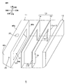
- FIG. 1 shows a perspective view of an embodiment of a coating apparatus of the present invention.
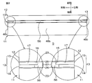
- FIG. 2 shows a plan view of the nozzle of the coating apparatus of FIG.
- FIG. 3 shows a bottom view of the nozzle of FIG.
- FIG. 4 shows a side view of the nozzle of FIG.
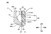
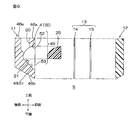
- FIG. 5 shows a side sectional view of the nozzle of FIG. 2 along the line AA.
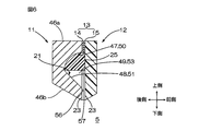
- FIG. 6 shows a side sectional view of the nozzle of FIG. 2 along the line BB.
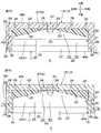
- 7A-7B are front sectional views of the nozzle of FIG. 2
- FIG. 7A is a front sectional view showing the first shim without the second shim
- FIG. 7B is a front sectional view showing the second shim. Indicates.
- FIG. 7A is a front sectional view showing the first shim without the second shim
- FIG. 7B is a front sectional view showing the second shim. Indicates.
- FIG. 7A is a
- FIG. 8 shows an exploded perspective view of the nozzle of FIG.
- FIG. 9 shows an exploded side sectional view of the nozzle of FIG.
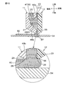
- FIG. 10 shows a state in which the varnish is applied by the nozzle shown in FIG.
- FIG. 11 shows the bottom view of the nozzle of other embodiment of the coating device of this invention.
- FIG. 12 shows a bottom view of a nozzle of another embodiment of the coating apparatus of the present invention.
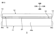
- FIG. 13 shows the bottom view of the nozzle of other embodiment of the coating device of this invention.
- FIG. 14 shows the front sectional drawing of the nozzle of other embodiment of the coating device of this invention.
- FIG. 15 is an image processing diagram of a photograph of a nozzle varnish of the coating apparatus of Example 1.
- FIG. 16 is an image processing diagram of a photograph of a nozzle varnish of the coating apparatus of Comparative Example 1.
- the left-right direction of the paper surface is “left-right direction” (first direction or width direction)
- the vertical direction of the paper surface is “front-back direction” (second direction or thickness direction)
- the thickness direction is “up-down direction” (first direction) 3 directions or discharge directions), specifically, in accordance with the direction arrow shown in FIG.
- the drawings other than FIG. 2 are also based on the direction of FIG.
- the second block 12 (described later) is omitted in order to clearly show the relative arrangement of the manifold 21 (described later), the shim 13 (described later), and the attachment member 25 (described later).
- the attachment member 25 is omitted in order to clearly show the relative arrangement of the shim 13, the first block 11, and the second block 12.
- the first shim 14 (described later) is omitted in order to clearly show the shape of the second shim 15 (described later).
- the coating device 1 is a coating device for coating a varnish containing particles and a resin (described in detail later).
- the coating apparatus 1 includes a tank 2, a pump 3, and a nozzle 5.
- the tank 2, the pump 3 and the nozzle 5 are sequentially arranged from the upstream side to the downstream side in the discharge direction of the varnish.
- the tank 2 is a reservoir for storing the varnish, and is provided in the upper part of the coating apparatus 1.
- the pump 3 is connected to the tank 2 via the first pipe 61, and specifically, is disposed on the front side of the tank 2.
- the pump 3 is not particularly limited as long as the pump can discharge the varnish stored in the tank 2 with a predetermined pressure applied to the nozzle 5.
- the pump 3 can be a MONO pump (specifically, a Heisin MONO pump (Hyojin Equipment Co., Ltd.). Etc.) and a commercially available pump.
- the nozzle 5 is, for example, a slot die coater, and is specifically disposed below the pump 3 and connected to the pump 3 via a second pipe 69.
- the nozzle 5 is formed in a thick plate shape extending in the vertical direction and the horizontal direction.
- the nozzle 5 includes a first block 11, a second block 12 disposed to face the front side of the first block 11, and a shim 13 interposed between the first block 11 and the second block 12.
- the first block 11 is made of, for example, a metal such as stainless steel or a resin such as acrylic resin.
- the first block 11 is preferably made of metal from the viewpoint of durability.
- the first block 11 has a thick flat plate shape extending in the vertical direction and the horizontal direction.
- the first block 11 is formed in a substantially rectangular shape in a plan view and a front view.
- the upper part is formed in a substantially rectangular shape
- the lower part is formed in a substantially triangular shape whose length in the front-rear direction becomes shorter toward the lower side.
- the 1st block 11 is formed in the bottomed frame shape where the center part of the front surface is dented in the back side.
- the first block 11 integrally includes an upper wall 46a, a lower wall 46b, and a pair of side walls 46c.
- the upper wall 46a is formed in a substantially rectangular shape in plan view extending in the left-right direction and in a substantially rectangular shape in front view. Further, as shown in FIGS. 5 and 6, the upper wall 46a is formed so that the upper portion is substantially rectangular in a side view and the lower surface 47 of the lower portion is a curved surface. Specifically, the lower surface 47 of the upper wall 46a is formed in an arc shape that gradually curves downward as it goes rearward.
- the lower wall 46b is provided adjacent to the lower end of the upper wall 46a.
- the lower wall 46b is formed in a substantially rectangular shape in bottom view extending in the left-right direction and in a substantially rectangular shape in front view.
- the lower wall 46 b is formed as an inclined surface that is linearly inclined downward as the lower surface thereof is directed to the front side, and the upper surface 48 is directed to the front side, as viewed from the side. Accordingly, it is formed as an inclined surface inclined linearly downward.
- the upper end edge of the upper surface 48 of the lower wall 46b is formed to be continuous with the lower end edge of the lower surface 47 of the upper wall 46a.
- the pair of side walls 46c are continuous to both ends in the left-right direction of the upper wall 46a and the lower wall 46b, and are formed in a substantially rectangular shape in plan view extending in the up-down direction. Yes. Further, the side wall 46c is formed in a substantially triangular shape in which the upper part has a substantially rectangular shape in a side view and the lower part has a length in the front-rear direction that decreases toward the lower side.
- the front surfaces of the upper wall 46a, the lower wall 46b, and the pair of side walls 46c are formed in a substantially rectangular frame shape when viewed from the front. Further, as shown in FIGS. 5 and 7A-7B, in the first block 11, from the lower surface 47 of the upper wall 46a, the upper surface 48 of the lower wall 46b, and the inner surfaces (inner side surfaces) of the pair of side walls 46c, A manifold 21 is formed.
- the manifold 21 is provided to spread a varnish supplied from a supply hole 20 described later in the left-right direction.
- the manifold 21 includes an inflow portion 50 and an outflow portion 51.
- the inflow portion 50 is formed by the lower surface 47 of the upper wall 46a and the inner surfaces (inner surfaces) of the pair of side walls 46c.
- the inflow portion 50 is formed such that the opening cross-sectional area along the left-right direction and the front-rear direction (the direction orthogonal to the discharge direction) increases as it goes downward (downstream in the discharge direction).
- the inflow space 52 is partitioned by the inflow portion 50.
- the outflow portion 51 is formed by the upper surface 48 of the lower wall 46b and the inner surfaces (inner surfaces) of the pair of side walls 46c.
- the outflow portion 51 is formed such that the opening cross-sectional area along the left-right direction and the front-rear direction (the direction orthogonal to the discharge direction) decreases as it goes toward the discharge direction.
- the outflow space 53 is partitioned by the outflow portion 51 so as to communicate with the inflow space 52.
- This manifold 21 partitions the manifold space.
- the manifold space is formed by an inflow space 52 and an outflow space 53.
- the supply hole 20 penetrating the upper wall 46a in the vertical direction is formed in the upper wall 46a.
- the supply hole 20 is formed in the upper wall 46a in order to supply varnish to the cavity 49 (described later) from the pump 3 through the second pipe 69, and has a substantially cylindrical shape.
- the supply hole 20 is provided at a substantially central portion in the left-right direction of the upper wall 46 a in plan view.
- the lower end portion of the supply hole 20 is bent forward and obliquely downward, and is opened on the lower surface 47 of the upper wall 46a.
- the upper wall 46a and the pair of side walls 46c are formed with first fixing holes 28 that are perforated from the front to the rear.
- a plurality of first fixing holes 28 are provided at intervals.
- the first fixing holes 28 are formed at equal intervals in the left-right direction on the front surface of the upper wall 46a.
- the first fixing holes 28 are formed at equal intervals in the vertical direction on the front surfaces of the pair of side walls 46c.
- the pair of side walls 46c is formed with a second fixing hole 29 penetrating in the left-right direction.
- the second fixing hole 29 is provided at a position communicating with the inflow space 52 (see FIG. 5) in the pair of side walls 46c.
- an attachment member 25 is attached to the manifold 21.
- the two attachment members 25 are provided on the upper side (upstream side in the discharge direction) of the manifold 21 at intervals in the left-right direction.
- each attachment member 25 has a substantially rectangular shape in plan view extending in the left-right direction, and the outer side surface in the left-right direction is formed in a flat shape extending in the up-down direction. Further, the attachment member 25 has a fan shape when viewed from the side, the lower surface is formed as a flat surface, and the upper surface is formed in an arc shape that gradually curves downward as it goes rearward.
- the attachment member 25 is formed in a substantially triangular shape (specifically, a right triangle shape) when viewed from the front, as indicated by the hatching of thick and thin lines in FIGS. 7A-7B.
- the lower surfaces of the two attachment members 25 are formed as inclined surfaces that are inclined downwardly toward the outer side in the left-right direction when viewed from the front, and are disposed so as to face each other in the left-right direction.
- the attachment member 25 is formed with a protruding portion that slightly protrudes forward from the first block 11 when projected in the vertical direction and the horizontal direction.
- the left and right outer edges of the lower surface of the attachment member 25 are arranged so as to overlap the lower edge of the lower surface 47 of the upper wall 46a when projected in the front-rear direction. Yes.
- the left and right inner end edges of the lower surface of the attachment member 25 are adjacent to both left and right ends of the supply hole 20 and adjacent to both outer sides of the lower end of the supply hole 20 so as to expose the supply hole 20. Has been placed.
- an enlarged portion 33 is formed in the inflow space 52 of the cavity 49 that gradually increases in length in the left-right direction toward the lower side.
- the enlarged portion 33 is formed in a substantially inverted V shape so that the length in the left-right direction with respect to the supply hole 20 gradually increases as it goes downward.
- the second block 12 is a transparent member formed of a transparent material such as glass, acrylic resin (specifically, polymethyl methacrylate), or a transparent resin such as silicone resin.
- the second block 12 has a flat plate shape extending in the left-right direction, and the lower end portion is formed in a substantially triangular shape whose length in the front-rear direction becomes shorter toward the lower side.
- the second block 12 is formed so as to overlap the first block 11 when projected in the front-rear direction.
- the upper surface and both side surfaces of the second block 12 are formed flush with the upper surface and both side surfaces of the first block 11, and the lower end portion of the second block 12 is in the front-rear direction with the lower end portion of the first block 11. When projected, they are placed at the same position.
- the second block 12 is formed with a plurality of first fixing holes 28 (see FIGS. 7A-7B) having the same arrangement and size as the first block 11 in a front view.
- the shim 13 is made of the same material as that of the first block 11, for example.
- the shim 13 includes a first shim 14 and a second shim 15 disposed on the front side of the first shim 14.
- the first shim 14 is a thin plate formed in a substantially inverted U shape when viewed from the front with the lower side opened.
- the first shim 14 is arranged so as to overlap the front surface of the upper wall 46a of the first block 11 and the front surface of the pair of side walls 46c when projected in the front-rear direction.
- the second shim 15 is a thin plate formed in a substantially inverted U shape in front view with the lower side opened, as shown in FIG. 7B (see hatching indicated by thin lines) and FIG.
- the second shim 15 is formed so as to bulge inward from the first shim 14 in a front view. Specifically, when the second shim 15 is projected in the front-rear direction, the overlapping portion 17 that overlaps with the first shim 14 is exposed to the inner side in the left-right direction from the first shim 14, and the inner side from the overlapping portion 17 And a bulging portion 16 that bulges integrally.
- the bulging portion 16 is formed so as to bulge in a substantially rectangular shape inward in the left-right direction from the side wall facing portion 17 c facing the pair of side walls 46 c in the second shim 15. As shown in FIG. 7B, the bulging portion 16 has an upper end portion cut out in a substantially rectangular shape in front view so as not to overlap with the attachment member 25 when projected in the front-rear direction. Specifically, the bulging portion 16 is cut away from the inner end edge of the upper end portion toward both outer sides in the left-right direction.
- each of the first shim 14 and the second shim 15 is formed with a plurality of first fixing holes 28 (see FIG. 7) having the same arrangement and size as the first block 11 in a front view.
- the first block 11, the attachment member 25, the first shim 14, the second shim 15, and the second block 12 are prepared.
- the attachment member 25 is attached to the manifold 21 of the first block 11, and the shim 13 (the first shim 14 and the second shim 15) is attached to the front surface of the upper wall 46a and the front surface of the lower wall 46b (see FIGS. 7A-7B). ).
- a fixing member (not shown) is inserted into the second fixing hole 29 (see FIGS. 4 and 7A-7B) to reach the attachment member 25,
- the attachment member 25 is fixed to the manifold 21.
- the first shim 14 is brought into contact with the front surface of the upper wall 46a and the front surface of the lower wall 46b.
- the overlapping portion 17 of the second shim 15 is brought into contact with the front surface of the first shim 14.
- the second shim 15 is disposed on the first shim 14 so that the bulging portion 16 is exposed from the first shim 14 in the left-right direction.
- the attachment member 25 is passed through the cutout portion of the bulging portion 16 of the second shim 15.
- the rear surface of the second block 12 is brought into contact with the front surface of the second shim 15 and the front surface of the attachment member 25.
- a fixing member (not shown) is inserted through the first fixing holes 28 (see FIGS. 7A-7B) of the first block 11, the shim 13, and the second block 12 and fixed. Accordingly, the shim 13 (the first shim 14 and the second shim 15) is sandwiched between the first block 11 and the second block 12, and the nozzle 5 is assembled.
- the nozzle 5 is formed with a cavity 21 partitioned by the manifold 21 of the first block 11, the inner surface of the shim 13, and the rear surface of the second block 12.
- a slit 56 is formed which is partitioned by the front surface of the lower wall 46b of the first block 11, the inner side surface of the shim 13 (see FIGS. 7A-7B and FIG. 8), and the rear surface of the second block 12.
- the slit 56 is opened in a substantially rectangular shape in plan view extending in the left-right direction, and is also opened in a substantially rectangular shape in side view extending in the vertical direction.
- a slot 57 is opened at the lower end (discharge port) of the slit 56.
- the slot 57 is formed as a discharge port that is elongated in the left-right direction when viewed from the bottom.
- the slot 57 is formed as a discharge port in which the bulging portion 16 bulges at the front end portion in the left-right direction end portion.
- the bulging portion 16 reduces the opening cross-sectional area at the end in the left-right direction of the slot 57 relative to the opening cross-sectional area in the middle in the left-right direction (center portion) by the amount bulging from the first shim 14. Yes.
- the length in the front-rear direction is about 2 minutes compared with the length in the front-rear direction in the middle of the left-right direction (center portion) because the bulging portion 16 is provided at both ends in the left-right direction of the slot 57. 1.
- the discharge flow is reduced as compared with the center (in the middle) of the left and right direction of the slot 57 where the opening cross sectional area is maintained because the opening cross sectional area is reduced.
- the lower wall 46 b, the shim 13, and the second block 12 that partition the slit 56 serve as the discharge unit 23.
- the dimensions of the nozzle 5 are appropriately set according to the physical properties (including viscosity) of the varnish, the shape and / or thickness of the coating film 60 (see FIG. 10), and are not particularly limited.
- the width (length in the left-right direction) of the nozzle 5 is, for example, 30 mm or more, preferably 50 mm or more, and, for example, 500 mm or less, preferably 200 mm or less.
- the internal diameter of the supply hole 20 is 2 mm or more, for example, Preferably, it is 5 mm or more, for example, is 30 mm or less, Preferably, it is 15 mm or less.
- the width (length in the left-right direction) of the cavity 49, the slit 56, and the slot 57 is, for example, 10 mm or more, preferably 30 mm or more, and, for example, 450 mm or less, preferably 150 mm or less.
- the length of the inflow space 52 in the vertical direction is, for example, 3 mm or more, preferably 5 mm or more, for example, 80 mm or less, preferably 50 mm or less, and the length in the front-rear direction is, for example, 3 mm or more.
- the thickness is preferably 5 mm or more, and for example, 50 mm or less, preferably 30 mm or less.
- the vertical length of the outflow space 53 is, for example, 3 mm or more, preferably 5 mm or more, and for example, 80 mm or less, preferably 50 mm or less.
- the width (length in the left-right direction) of the attachment member 25 is, for example, 5 mm or more, preferably 15 mm or more, and for example, 200 mm or less, preferably 70 mm or less.
- the vertical length of the attachment member 25 is, for example, 3 mm or more, preferably 5 mm or more, and for example, 80 mm or less, preferably 50 mm or less.
- the length in the front-rear direction of the attachment member 25 is, for example, 3 mm or more, preferably 5 mm or more, and, for example, 50 mm or less, preferably 30 mm or less.
- the length of the slit 56 in the front-rear direction and the length of the slot 57 (discharge port) in the front-rear direction are substantially the same as the length of the shim 13 in the front-rear direction, for example, 0.1 mm or more, preferably 0.5 mm or more. Also, for example, 3 mm or less, preferably 2 mm or less.
- the thickness of the first shim 14 is, for example, 0.05 mm or more, preferably 0.2 mm or more, and, for example, 3 mm or less, preferably 1.5 mm or less.
- the thickness of the second shim 15 is, for example, the same as that of the first shim 14, specifically, for example, 0.05 mm or more, preferably 0.2 mm or more, and, for example, 3 mm or less, Preferably, it is 1.5 mm or less.
- the bulging length (left-right direction length) of the bulging part 16 is 0.2 mm or more, for example, Preferably, it is 1 mm or more, for example, is 6 mm or less, Preferably, it is 3 mm or less.
- the coating device 1 is provided with a moving device 55 that can move the nozzle 5 in the front-rear direction, the left-right direction, and / or the up-down direction, adjacent to the upper side of the pump 3. .
- the varnish contains particles and resin as essential components.
- the particles are appropriately set according to the application and purpose of the coating, and examples thereof include phosphors and fillers.
- the phosphor has a wavelength conversion function, and examples thereof include a yellow phosphor capable of converting blue light into yellow light, and a red phosphor capable of converting blue light into red light.
- yellow phosphor examples include silicate phosphors such as (Ba, Sr, Ca) 2 SiO 4 ; Eu, (Sr, Ba) 2 SiO 4 : Eu (barium orthosilicate (BOS)), for example, Y 3 Al Garnet-type phosphors having a garnet-type crystal structure such as 5 O 12 : Ce (YAG (yttrium, aluminum, garnet): Ce), Tb 3 Al 3 O 12 : Ce (TAG (terbium, aluminum, garnet): Ce) Examples thereof include oxynitride phosphors such as Ca- ⁇ -SiAlON.
- silicate phosphors such as (Ba, Sr, Ca) 2 SiO 4 ; Eu, (Sr, Ba) 2 SiO 4 : Eu (barium orthosilicate (BOS)
- Y 3 Al Garnet-type phosphors having a garnet-type crystal structure such as 5 O 12 : Ce (YAG (yttrium, aluminum, garnet): Ce
- red phosphor examples include nitride phosphors such as CaAlSiN 3 : Eu and CaSiN 2 : Eu.
- Examples of the shape of the phosphor include a spherical shape, a plate shape, and a needle shape.
- spherical shape is mentioned from a fluid viewpoint.
- the average value of the maximum length of the phosphor (in the case of a sphere, the average particle diameter) is, for example, 0.1 ⁇ m or more, preferably 1 ⁇ m or more, and for example, 200 ⁇ m or less, preferably 100 ⁇ m or less. But there is.
- the specific gravity of the phosphor is, for example, 2.0 or more, for example, 9.0 or less.
- Fluorescent substances can be used alone or in combination.
- the blending ratio of the phosphor is, for example, 0.1 parts by mass or more, preferably 0.5 parts by mass or more, for example, 80 parts by mass or less, preferably 60 parts by mass or less with respect to 100 parts by mass of the resin. But there is.
- the filler is blended into the varnish to improve the toughness of the coating film, and examples thereof include organic fine particles such as silicone particles, and inorganic fine particles such as silica, talc, alumina, aluminum nitride, and silicon nitride.
- the specific gravity of the filler is, for example, 0.5 or more, and, for example, 7.0 or less.
- the average value of the maximum length of the filler (in the case of a spherical shape, the average particle diameter) is, for example, 0.1 ⁇ m or more, preferably 0.5 ⁇ m or more, and, for example, 200 ⁇ m or less, preferably It is also 100 ⁇ m or less.
- ⁇ Fillers can be used alone or in combination.
- the blending ratio of the filler is, for example, 0.1 parts by mass or more, preferably 0.5 parts by mass or more, and, for example, 70 parts by mass or less, preferably 50 parts by mass with respect to 100 parts by mass of the resin. It is also below the department.
- the total amount of the phosphor and the filler is, for example, 0.1 parts by mass or more, preferably 0.5 mass with respect to 100 parts by mass of the resin.
- Part or more for example, 80 parts by mass or less, preferably 60 parts by mass or less.
- the resin examples include curable resins such as silicone resin, epoxy resin, polyimide resin, phenol resin, urea resin, melamine resin, and unsaturated polyester resin.
- the resin examples include polyolefin (eg, polyethylene, polypropylene, ethylene-propylene copolymer), acrylic resin (eg, polymethyl methacrylate), polyvinyl acetate, ethylene-vinyl acetate copolymer, polychlorinated resin.
- the resin is preferably a curable resin, more preferably a curable silicone resin.
- curable silicone resin examples include a two-stage curable silicone resin and a one-stage curable silicone resin.
- the two-stage curable silicone resin has a two-stage reaction mechanism, and is curable by B-stage (semi-curing) by the first-stage reaction and C-stage (full-curing) by the second-stage reaction. Silicone resin.
- the B stage is a state in which the two-stage curable silicone resin is between the A stage soluble in the solvent and the fully cured C stage, and the curing and gelation progresses slightly, and the solvent swells. However, it is not completely dissolved and is softened by heating but not melted.
- the one-step curable silicone resin has a one-step reaction mechanism and is a curable silicone resin that is completely cured by the first-step reaction.
- the curable silicone resin examples include a thermosetting silicone resin that is cured by heating, such as an active energy ray-curable silicone resin that is cured by irradiation with active energy rays (for example, ultraviolet rays and electron beams). .
- a thermosetting silicone resin is used.
- the specific gravity of the resin is, for example, lighter than the specific gravity of the phosphor and / or filler, specifically, for example, 0.5 or more, and, for example, 2.0 or less.
- the blending ratio of the resin is, for example, 0.1% by mass or more, preferably 0.5% by mass or more, and for example, less than 100% by mass, preferably 99.5% by mass or less with respect to the varnish. It is.
- arbitrary components such as a solvent and an additive, can be mix
- the solvent include aliphatic hydrocarbons such as hexane, aromatic hydrocarbons such as xylene, and siloxanes such as vinylmethyl cyclic siloxane and both-end vinyl polydimethylsiloxane.
- additives examples include surface conditioners such as dispersants, silane coupling agents, and leveling agents.
- a varnish is prepared by blending the above components and stirring and mixing them.
- the viscosity of the varnish at 25 ° C. and 1 atm is, for example, 1,000 mPa ⁇ s or more, preferably 4,000 mPa ⁇ s or more, and, for example, 1,000,000 mPa ⁇ s or less, preferably , 100,000 mPa ⁇ s or less.
- the viscosity is measured at a rotational speed of 99 s -1 by adjusting the temperature of the varnish to 25 ° C. and using an E-type cone.
- the base material 54 is prepared.
- the base material 54 is formed in a sheet shape, and the outer shape thereof is not particularly limited.
- the base material 54 is formed in a substantially rectangular shape in plan view (including a strip shape and a long shape). ing.
- the base material 54 is arrange
- the base material 54 is formed in a sheet shape from a resin such as a polyester resin such as polyethylene terephthalate (PET), for example, a polyolefin resin such as polypropylene. Moreover, the base material 54 can also be formed from a metal, for example. The surface of the substrate 54 can be subjected to a peeling treatment or the like.
- a resin such as a polyester resin such as polyethylene terephthalate (PET), for example, a polyolefin resin such as polypropylene.
- PET polyethylene terephthalate
- the base material 54 can also be formed from a metal, for example.
- the surface of the substrate 54 can be subjected to a peeling treatment or the like.
- the discharge unit 23 (slot 57) of the nozzle 5 is opposed to the base material 54, and the discharge unit 23 is brought close to the base material 54.
- the vertical length of the doctor 26 and the base material 54 is set to, for example, a desired thickness of the coating film 60 (see FIG. 10) or more, for example, the same thickness. It is 10 ⁇ m or more, preferably 30 ⁇ m or more, and is set to, for example, 3000 ⁇ m or less, preferably 2800 ⁇ m or less.
- the pump 3 is driven and the nozzle 5 is horizontally moved forward by the moving device 55.
- the varnish is guided from the tank 2 to the supply hole 20 (see FIG. 5) through the first pipe 61, the pump 3, and the second pipe 69 by driving the pump 3.
- the varnish flows into the inflow space 52 and gradually expands in the left-right direction in the enlarged portion 33 as shown in FIGS. 7A-7B, and into the outflow space 53 by driving the pump 3 and / or gravity. Leaked. Subsequently, in the outflow space 53, as shown in FIG. 6, the varnish flows downward and reaches the slit 56 while being narrowed in the front-rear direction.
- the flow at both ends in the left-right direction (both ends in the first direction) is suppressed by the bulging portion 16, while the discharge at the both ends in the left-right direction is also suppressed by the bulging portion 16 in the discharge portion 23.
- the ink is discharged from the slot 57 toward the base material 54.
- the thickness of the varnish discharged to the base material 54 is adjusted by the doctor 26 of the first block 11 of the nozzle 5 that moves forward.
- the varnish is dried to form the coating film 60.
- the coating film 60 can be formed in a single wafer type by intermittently applying the varnish to the base material 54, or by continuously discharging the varnish to the base material 54, The coating film 60 can also be formed continuously. After that, the continuous coating film 60 can be made into a single wafer type by external processing such as cutting.
- the resin contains a curable resin
- a curing treatment is performed by heat or active energy rays. Thereby, the coating film 60 after the curing (or after the semi-curing) is formed.
- the resin contains a thermoplastic resin
- a heater is provided in the coating apparatus 1 and the above-described treatment is performed while the resin is melted or softened.
- the bulging portion 16 can relatively suppress the discharge of the varnish at the left and right ends of the discharge portion 23. That is, the discharge of the varnish at both ends in the left-right direction of the discharge unit 23 can be suppressed with respect to the discharge of the varnish at the middle part in the left-right direction of the discharge unit 23. Therefore, the bulge in the thickness direction at both left and right end portions of the coating film 60 can be suppressed, and the flatness of the coating film 60 can be ensured.
- the inflow space 52 has a larger opening cross-sectional area along the direction perpendicular to the discharge direction than the supply hole 20, and the opening cross-sectional area in the inflow space 52 expands downward. Can be quickly expanded in the left-right direction.
- the opening cross-sectional area of the outflow space 53 decreases as it goes downward, the outflow space 53 can be fed into the slit 56 while applying pressure to the varnish.
- the attachment member 25 is configured to be detachable from the manifold 21, but, for example, the attachment member 25 may be configured integrally with the manifold 21 although not shown.
- the attachment member 25 is configured to be detachable from the manifold 21. According to such a coating device 1, it can be replaced with an attachment member 25 having a desired shape according to the characteristics of the varnish. Specifically, the inclination angle of the lower surface (inclined surface) of the attachment member 25 is changed according to the viscosity of the varnish.
- the inclination angle of the (inclined surface) of the attachment member 25 described above is determined according to the type of particles, the mixing ratio, the shape, the average particle diameter, the type of resin, the mixing ratio, the viscosity, etc. It is possible to easily prevent the varnish from staying as described above.
- the second block 12 is a transparent member, it can also be an opaque member made of metal, for example.
- the second block 12 is a transparent member. According to such a coating apparatus 1, since the varnish which passes the cavity 49 containing the enlarged part 33 can be visually observed through the 2nd block 12 which is a transparent member, the state of the particle
- the part (for example, window part) facing the enlarged part 33 ) May be formed of a transparent material, and the other part may be an opaque member.
- the nozzle 5 is moved with respect to the base material 54.
- the base material 54 and the nozzle 5 only need to move relative to each other.
- the substrate 54 can also be moved.
- the nozzle 5 is provided so that the slot 57 faces downward, but it can also be directed sideways or upward, for example.
- the bulging portion 16 is provided in the second shim 15, but it can also be provided in the first shim 14, for example, as shown in FIG.
- the two bulging portions 16 are both provided in the second shim 15.
- one bulging portion 16 is connected to the second shim of the right side portion. 15 and the other bulging portion 16 can be provided on the first shim 14 on the left side.
- the bulging portion 16 is formed in a substantially rectangular shape when viewed from the bottom.
- the bulging portion 16 can also be formed in a triangular shape.
- the bulging portion 16 is formed over the portion corresponding to the cavity 49 and the slit 56.
- the bulging portion 16 is formed only in the portion corresponding to the slit 56. You can also
- the nozzle 5 is moved forward, but the moving direction is not limited to this, and for example, the nozzle 5 can be moved backward. In this case, as shown in FIG. 10, the thickness of the coating film 60 is adjusted by the doctor 26 of the second block 12.
- each part in the nozzle 5 can be subjected to processing such as chamfering.
- Example 1 Preparation of varnish> 80 parts by mass of liquid silicone resin (LR7665 A solution, one-step curable silicone resin, specific gravity 1.0, manufactured by Shin-Etsu Chemical Co., Ltd.), silicone particles (Tospearl 2000B, specific gravity 1.32, Momentive Performance Materials, 20 parts by mass of Japan) and 15 parts by mass of YAG: Ce (Y-468, specific gravity 4.5, yellow phosphor, manufactured by Nemoto Lumi Materials) are added, and these are stirred and mixed. A varnish was prepared.
- liquid silicone resin LR7665 A solution, one-step curable silicone resin, specific gravity 1.0, manufactured by Shin-Etsu Chemical Co., Ltd.
- silicone particles Tospearl 2000B, specific gravity 1.32, Momentive Performance Materials, 20 parts by mass of Japan
- YAG: Ce Y-468, specific gravity 4.5, yellow phosphor, manufactured by Nemoto Lumi Materials
- the viscosity of the varnish at 25 ° C. and 1 atm was 40,000 mPa ⁇ s.
- a coating apparatus including a tank, a pump, a nozzle (including an attachment member and a bulging portion), and a moving device was prepared.
- the dimensions of the nozzle are shown below.
- Nozzle width 70mm Inside diameter of supply hole 10.5mm Cavity width (maximum length in the left-right direction) 54 mm
- the vertical length of the inflow space is 10mm
- the length of the inflow space in the longitudinal direction Length of outflow space in the vertical direction 10mm Attachment member width 22mm
- 10mm vertical length of attachment member Attachment member length 10mm Slot width (maximum length in the left-right direction) 50 mm Length of slit in the front-rear direction 1mm
- the thickness of the first shim (length in the front-rear direction) 0.4 mm
- the thickness of the second shim (length in the front-rear direction) 0.6 mm
- the bulging length of the bulging part (length in the left-right direction) 3 mm
- the prepared varnish was put into a tank, and a base material made of PET was prepared separately.
- the nozzle slot was made to face the substrate so that the vertical length of the doctor and the substrate was 400 ⁇ m by the moving device.
- the pump was driven and the nozzle was moved horizontally by 140 mm forward by the moving device.
- Comparative Example 1 A coating film was produced in the same manner as in Example 1 except that the attachment member was not attached to the nozzle.
- Example 1 Compared with Comparative Example 1, in Example 1, a dilute portion of YAG: Ce (yellow phosphor) was not confirmed in the varnish, and it was found that YAG: Ce (yellow phosphor) was uniform.
- the coating device is used for coating film production.
Landscapes
- Coating Apparatus (AREA)
Abstract
塗布装置(1)は、粒子および樹脂を含むワニスを塗布するための塗布装置(1)である。塗布装置(1)は、ワニスを、吐出方向と直交する第1方向に広げるためのマニホールド(21)と、マニホールド(21)によって第1方向に広げられたワニスを吐出するための吐出部(23)とを備える。マニホールド(21)には、第1方向長さが、吐出方向下流側に向かうに従って、次第に長くなる拡大部(33)が設けられる。吐出部(23)には、吐出部(23)の第1方向端部におけるワニスの吐出を相対的に抑制するための吐出抑制部(16)が設けられている。
Description
本発明は、塗布装置、詳しくは、粒子および樹脂を含むワニスを塗布するための塗布装置に関する。
従来、樹脂を含むワニスを塗布するための塗布装置が種々知られている。
また、ワニスが非ニュートン流体である場合、あるいは、ワニスと、ワニスが塗布される基材との親和性が低い場合には、塗膜の両端部が中央部に比べて盛り上がる盛り上がり部分を生じる場合がある。このような盛り上がり部分は、上記した塗膜の平坦性を損なう。
例えば、塗布基材に塗布液を供給するためのスロットが形成されたスロットダイを備え、スロットが塗布基材に対向し、塗布基材に対向するスロットの断面が、その両端部において塗布液の供給を相対的に抑制する形状に形成されるスロットダイ塗布装置が提案されている(例えば、下記特許文献1参照)。
しかるに、粒子をさらに含むワニスを、特許文献1に記載のスロットダイ塗布装置で塗布すると、スロットの両端部において、吐出流れが低下していることから、スロットダイのマニホールドの両端部において、吐出圧が低下するので、ワニスの流れが著しく緩慢になる。そのため、ワニスが滞留し易く、そのようなワニスの滞留部分では、粒子の比重が相対的に大きいと、粒子が沈降する。そのため、滞留部分における粒子の分布が不均一、さらには、マニホールドにおける粒子の分布が不均一になり易いという不具合がある。その結果、塗膜における粒子の分布が不均一になるという不具合がある。
本発明の目的は、塗膜の平坦性を確保しながら、塗膜における粒子の均一性を確保することのできる塗布装置を提供することにある。
上記目的を達成するために、本発明の塗布装置は、粒子および樹脂を含むワニスを塗布するための塗布装置であり、ワニスを、吐出方向と直交する第1方向に広げるためのマニホールドと、前記マニホールドによって前記第1方向に広げられたワニスを吐出するための吐出部とを備え、前記マニホールドには、前記第1方向長さが、前記吐出方向下流側に向かうに従って、次第に長くなる拡大部が設けられ、前記吐出部には、前記吐出部の前記第1方向端部における前記ワニスの吐出を相対的に抑制するための吐出抑制部が設けられていることを特徴としている。
この装置では、吐出抑制部によって、吐出部の第1方向端部におけるワニスの吐出を相対的に抑制することができる。そのため、塗膜の第1方向端部における盛り上がりを抑制して、塗膜の平坦性を確保することができる。
一方、この塗布装置では、吐出部の第1方向端部において、ワニスの吐出流れが低下すると、マニホールドを通過するワニスは、拡大部において、吐出方向下流側に向かうに従って、第1方向外側に次第に広げられるので、ワニスが粒子を含むことに起因するワニスの吐出流れが緩慢になることを防止し、ワニスの滞留が生じることを防止することができる。その結果、マニホールドにおいてワニスにおける粒子の不均一性を解消することができる。従って、得られる塗膜の平坦性を確保しながら、塗膜における粒子の均一性を十分に確保することができる。
また、本発明の塗布装置では、前記マニホールドは、ワニスが流入され、前記吐出方向に対する直交方向に沿う開口断面積が、前記吐出方向下流側に向かうに従って拡大する流入部と、前記流入部の前記吐出方向下流側に設けられ、ワニスが前記流入部から流出され、前記直交方向に沿う開口断面積が、前記吐出方向に向かうに従って縮小する流出部とを備え、前記拡大部は、前記流入部に設けられていることが好適である。
マニホールドにおいて、直交方向に沿う開口断面積が吐出方向下流側に向かうに従って拡大する流入部では、直交方向に沿う開口断面積が吐出方向に向かうに従って縮小する流出部に比べて、上記したワニスの吐出流れが緩慢になり易く、それに起因するワニスの滞留を生じ易い。
しかし、この塗布装置では、拡大部が流入部に設けられているので、上記したワニスの吐出流れが緩慢になることを防止して、ワニスの滞留が生じることを防止することができる。
また、本発明の塗布装置には、前記拡大部を区画するための、前記マニホールドに対して着脱可能なアタッチメント部材が、前記マニホールドの前記吐出方向上流側における前記第1方向端部に設けられていることが好適である。
この塗布装置によれば、アタッチメント部材が、マニホールドに対して着脱可能であるので、ワニスの特性に応じて、所望形状のアタッチメント部材に交換することができる。
また、本発明の塗布装置は、前記拡大部を通過するワニスを目視することのできる透明部材を備えていることが好適である。
この塗布装置によれば、透明部材を介して、拡大部を通過するワニスを目視することができるので、ワニスにおける粒子の状態を簡単に検査することができる。
本発明の塗布装置によれば、得られる塗膜における粒子の均一性を十分に確保することができる。
図1~図10を参照して、本発明の塗布装置の一実施形態について説明する。
図2において、紙面左右方向を「左右方向」(第1方向あるいは幅方向)とし、紙面上下方向を「前後方向」(第2方向あるいは厚み方向)とし、紙厚方向を「上下方向」(第3方向あるいは吐出方向)とし、具体的には、図2に記載の方向矢印に準拠する。図2以外の図面についても、図2の方向を基準とする。
なお、図7Aおよび図7Bにおいて、マニホールド21(後述)、シム13(後述)およびアタッチメント部材25(後述)の相対配置を明確に示すために、第2ブロック12(後述)を省略している。さらに、図8において、シム13、第1ブロック11および第2ブロック12の相対配置を明確に示すために、アタッチメント部材25を省略している。また、図7Bにおいて、第2シム15(後述)の形状を明確に示すために、第1シム14(後述)を省略している。
図1において、この塗布装置1は、粒子および樹脂を含むワニス(後で詳述する)を塗布するための塗布装置である。塗布装置1は、タンク2と、ポンプ3と、ノズル5とを備える。タンク2、ポンプ3およびノズル5は、ワニスの吐出方向上流側から下流側に向かって、順次配置されている。
タンク2は、ワニスを貯蔵するリザーバであって、塗布装置1の上側部分に設けられている。
ポンプ3は、タンク2と第1配管61を介して接続されており、具体的には、タンク2の前側に配置されている。ポンプ3は、タンク2内に貯蔵されるワニスをノズル5に所定の圧力を負荷して吐出できるポンプであれば特に限定されず、例えば、モーノポンプ(具体的には、ヘイシンモーノポンプ(兵神装備社製)として市販されるポンプなど)などが挙げられる。
図1に示すように、ノズル5は、例えば、スロットダイコータであって、具体的には、ポンプ3の下側に配置されており、ポンプ3に第2配管69を介して接続されている。ノズル5は、上下方向および左右方向に延びる厚肉平板形状に形成されている。ノズル5は、第1ブロック11と、第1ブロック11の前側に対向配置される第2ブロック12と、第1ブロック11および第2ブロック12の間に介在するシム13とを備える。
第1ブロック11は、例えば、ステンレスなどの金属、あるいは、アクリル樹脂などの樹脂から形成されている。第1ブロック11は、好ましくは、耐久性の観点から、金属から形成されている。
図2および図8に示すように、第1ブロック11は、上下方向および左右方向に延びる厚肉平板形状をなし、具体的には、平面視および正面視において、略矩形状に形成され、側面視において、上側部分が略矩形状に形成され、下側部分が、下側に向かうに従って前後方向長さが短くなる略三角形状に形成されている。また、第1ブロック11は、前面の中央部が後側に凹む有底枠形状に形成されている。第1ブロック11は、上壁46aと、下壁46bと、1対の側壁46cとを一体的に備える。
上壁46aは、左右方向に延びる平面視略矩形状、かつ、正面視略矩形状に形成されている。また、上壁46aは、図5および図6に示すように、側面視において、上側部分が略矩形状をなし、下側部分の下面47が湾曲面となるように形成されている。具体的には、上壁46aの下面47は、後方に向かうに従って次第に下側に湾曲する円弧形状に形成されている。
下壁46bは、上壁46aの下端部に隣接して設けられている。下壁46bは、図3および図7A-7Bに示すように、左右方向に延びる底面視略矩形状、かつ、正面視略矩形状に形成されている。また、下壁46bは、図5および図6に示すように、側面視において、その下面が前側に向かうに従って下方に直線状に傾斜する傾斜面として形成されるとともに、その上面48が前側に向かうに従って下方に直線状に傾斜する傾斜面として形成される。下壁46bの上面48の上端縁は、上壁46aの下面47の下端縁に連続するように形成されている。
1対の側壁46cは、図7A-7Bおよび図8に示すように、上壁46aおよび下壁46bの左右方向両端部に連続しており、上下方向に延びる平面視略矩形状に形成されている。また、側壁46cは、側面視において、上側部分が略矩形状をなし、下側部分が、下側に向かうに従って前後方向長さが短くなる略三角形状に形成されている。
そして、第1ブロック11では、上壁46a、下壁46bおよび1対の側壁46cの前面が、面一の正面視略矩形枠状に形成されている。また、図5および図7A-7Bに示すように、第1ブロック11では、上壁46aの下面47と、下壁46bの上面48と、1対の側壁46cの内面(内側面)とから、マニホールド21が形成される。マニホールド21は、後述する供給孔20から供給されるワニスを左右方向に広げるために設けられる。
具体的には、マニホールド21は、流入部50および流出部51を備える。
流入部50は、上壁46aの下面47と、1対の側壁46cの内面(内側面)とによって形成される。流入部50は、左右方向および前後方向(吐出方向に対する直交方向)に沿う開口断面積が、下方(吐出方向下流側)に向かうに従って拡大するように、形成されている。この流入部50によって、流入空間52が仕切られる。
流出部51は、下壁46bの上面48と、1対の側壁46cの内面(内側面)とによって形成される。流出部51は、左右方向および前後方向(吐出方向に対する直交方向)に沿う開口断面積が、吐出方向に向かうに従って縮小するように、形成されている。この流出部51によって、流出空間53が、流入空間52に連通するように、仕切られる。
このマニホールド21によって、マニホールド空間が仕切られる。
マニホールド空間は、流入空間52と、流出空間53とから形成される。
また、上壁46aには、上壁46aを上下方向に貫通する供給孔20が形成されている。供給孔20は、ポンプ3から第2配管69を介してワニスをキャビティ49(後述する)に供給するために上壁46aに形成されており、略円柱形状にされている。また、図2に示すように、供給孔20は、平面視において、上壁46aの左右方向略中央部に設けられている。なお、図5に示すように、供給孔20の下端部は、下側斜め前方に屈曲して、上壁46aの下面47に開口されている。
また、図7A-7Bに示すように、上壁46aおよび1対の側壁46cには、それらの前面から後方に向かって穿孔される第1固定孔28が形成される。第1固定孔28は、互いに間隔を隔てて複数設けられている。具体的には、第1固定孔28は、上壁46aの前面において、左右方向に等間隔を隔てて形成されている。また、第1固定孔28は、1対の側壁46cの前面において、上下方向に等間隔を隔てて形成されている。
さらに、図4および図7A-7Bに示すように、1対の側壁46cには、左右方向を貫通する第2固定孔29が形成されている。第2固定孔29は、1対の側壁46cにおいて、流入空間52(図5参照)に連通する位置に設けられている。
そして、図6および図7A-7Bに示すように、マニホールド21には、アタッチメント部材25が装着されている。
アタッチメント部材25は、マニホールド21の上側(吐出方向上流側)部分において、左右方向に互いに間隔を隔てて2つ設けられている。
各アタッチメント部材25は、図2の破線および図6に示すように、左右方向に延びる平面視略矩形状をなし、その左右方向外側面が、上下方向に延びる平坦状に形成されている。また、アタッチメント部材25は、側面視扇状をなし、その下面が平坦面に形成されており、上面が、後方に向かうに従って次第に下側に湾曲する円弧形状に形成されている。アタッチメント部材25は、図7A-7Bの太線および細線のハッチングで示されるように、正面視略三角形状(具体的には、直角三角形状)に形成されている。また、2つのアタッチメント部材25の下面は、正面視において、左右方向外側に向かうに従って下側に傾斜する傾斜面として形成されており、それらは、左右方向に互いに対向するように配置されている。
また、図6に示すように、アタッチメント部材25には、上下方向および左右方向に投影したときに、第1ブロック11から前側にわずかに突出する突出部分が形成されている。
図6および図7A-7Bに示すように、アタッチメント部材25の下面の左右方向両外端縁は、前後方向に投影したときに、上壁46aの下面47の下端縁に重なるように配置されている。また、アタッチメント部材25の下面の左右方向内端縁は、供給孔20の左右方向両端部に隣接して、供給孔20を露出するように、供給孔20の下端部の左右方向両外側に隣接配置されている。
このアタッチメント部材25がマニホールド21に装着されることによって、キャビティ49の流入空間52に、左右方向長さが、下側に向かうに従って、次第に長くなる拡大部33が形成される。
拡大部33は、供給孔20を中心として、その左右方向長さが、下方に向かうに従って、次第に長くなるように、略逆V字形状に形成されている。
第2ブロック12は、例えば、ガラス、アクリル樹脂(具体的には、ポリメタクリル酸メチル)、シリコーン樹脂などの透明樹脂などの透明材料から形成される透明部材である。
第2ブロック12は、図8に示すように、左右方向に延びる平板形状をなし、下端部が、下側に向かうに従って前後方向長さが短くなる略三角形状に形成されている。また、第2ブロック12は、前後方向に投影したときに、第1ブロック11と重複するように形成されている。第2ブロック12の上面および両側面は、第1ブロック11における上面および両側面と面一に形成され、また、第2ブロック12の下端部は、第1ブロック11における下端部と、前後方向に投影したときに、同一位置に配置されている。
なお、図示しないが、第2ブロック12には、正面視において、第1ブロック11と同じ配置および大きさの複数の第1固定孔28(図7A-7B参照)が形成されている。
シム13は、例えば、第1ブロック11と同様の材料から形成されている。シム13は、第1シム14と、第1シム14の前側に配置される第2シム15とを備える。
第1シム14は、下側が開放される正面視略逆U字形状に形成される薄板である。第1シム14は、前後方向に投影したときに、第1ブロック11の上壁46aの前面および1対の側壁46cの前面と重複するように配置されている。
第2シム15は、図7B(細線で示すハッチング参照)および図8に示すように、下側が開放される正面視略逆U字形状に形成される薄板である。また、第2シム15は、正面視において、第1シム14より内側に膨出するように形成されている。具体的には、第2シム15は、前後方向に投影したときに、第1シム14と重複する重複部17と、第1シム14から左右方向内側に露出し、かつ、重複部分17から内側に膨出する膨出部16とを一体的に備える。
膨出部16は、第2シム15における1対の側壁46cと対向する側壁対向部17cから左右方向内側に略矩形状に膨出するように形成されている。図7Bに示すように、膨出部16は、前後方向に投影したときに、アタッチメント部材25に重複しないように、上端部分が正面視略矩形状に切り欠かれている。詳しくは、膨出部16は、上端部の内端縁から左右方向両外側に向かって切り欠かれている。
また、第1シム14および第2シム15のそれぞれには、正面視において、第1ブロック11と同じ配置および大きさの複数の第1固定孔28(図7参照)が形成されている。
次に、ノズル5の組み付けについて、図8および図9を参照して説明する。
まず、第1ブロック11、アタッチメント部材25、第1シム14、第2シム15および第2ブロック12のそれぞれを用意する。
次いで、第1ブロック11のマニホールド21に、アタッチメント部材25を装着するとともに、上壁46aの前面および下壁46bの前面(図7A-7B参照)にシム13(第1シム14および第2シム15)を配置する。
具体的には、アタッチメント部材25を、マニホールド21に嵌め込んだ後、図示しない固定部材を第2固定孔29(図4および図7A-7B参照)に挿通し、アタッチメント部材25に到達させ、これによって、アタッチメント部材25をマニホールド21に固定する。
また、第1シム14を、上壁46aの前面および下壁46bの前面に接触させる。
続いて、第2シム15の重複部分17を第1シム14の前面に接触させる。この際、膨出部16が、第1シム14から左右方向内側に露出するように、第2シム15を第1シム14に配置する。また、第2シム15の膨出部16の切欠部分に、アタッチメント部材25を通過させる。
次いで、第2ブロック12の後面を、第2シム15の前面と、アタッチメント部材25の前面とに接触させる。続いて、図示しない固定部材を、第1ブロック11、シム13および第2ブロック12の第1固定孔28(図7A-7B参照)に挿通し、固定する。これによって、第1ブロック11および第2ブロック12によって、シム13(第1シム14および第2シム15)を挟み込み、ノズル5を組み付ける。
これによって、図5に示すように、ノズル5には、第1ブロック11のマニホールド21と、シム13の内側面と、第2ブロック12の後面とによって仕切られるキャビティ49とが形成される。
これとともに、第1ブロック11の下壁46bの前面と、シム13の内側面(図7A-7Bおよび図8参照)と、第2ブロック12の後面とによって仕切られるスリット56が形成される。スリット56は、左右方向に延びる平面視略矩形状に開口され、また、上下方向に延びる側面視略矩形状に開口されている。
また、図3および図5に示すように、スリット56の下端部(吐出口)は、スロット57が開口される。スロット57は、底面視において、左右方向に細長く延びる吐出口として形成される。
また、図3に示すように、スロット57は、その左右方向端部の前端部に膨出部16が膨出した吐出口として形成される。詳しくは、膨出部16は、第1シム14から膨出する分、スロット57の左右方向端部の開口断面積を、左右方向途中(中央部)の開口断面積に対して、減少させている。具体的には、スロット57の左右方向両端部では、膨出部16が設けられる分、その前後方向長さは、左右方向途中(中央部)の前後方向長さに比べて、約2分の1である。
そのため、スロット57は、左右方向両端部におけるワニス吐出流れは、膨出部16によって抑制される。
そのため、スロット57の左右方向両端部では、開口断面積が減少する分、開口断面積が維持されたスロット57の左右方向中央(途中)部に比べて、吐出流れが、低下する。
スリット56を仕切る下壁46b、シム13および第2ブロック12は、吐出部23とされる。
ノズル5の寸法は、ワニスの物性(粘度を含む)、塗膜60(図10参照)の形状および/または厚さによって適宜設定され、特に限定されない。ノズル5の幅(左右方向長さ)は、例えば、30mm以上、好ましくは、50mm以上であり、また、例えば、500mm以下、好ましくは、200mm以下である。また、供給孔20の内径は、例えば、2mm以上、好ましくは、5mm以上であり、また、例えば、30mm以下、好ましくは、15mm以下である。また、キャビティ49、スリット56およびスロット57の幅(左右方向長さ)は、例えば、10mm以上、好ましくは、30mm以上であり、また、例えば、450mm以下、好ましくは、150mm以下である。また、流入空間52の上下方向長さは、例えば、3mm以上、好ましくは、5mm以上であり、また、例えば、80mm以下、好ましくは、50mm以下であり、前後方向長さは、例えば、3mm以上、好ましくは、5mm以上であり、また、例えば、50mm以下、好ましくは、30mm以下である。流出空間53の上下方向長さは、例えば、3mm以上、好ましくは、5mm以上であり、また、例えば、80mm以下、好ましくは、50mm以下である。
また、アタッチメント部材25の幅(左右方向長さ)は、例えば、5mm以上、好ましくは、15mm以上であり、また、例えば、200mm以下、好ましくは、70mm以下である。また、アタッチメント部材25の上下方向長さは、例えば、3mm以上、好ましくは、5mm以上であり、また、例えば、80mm以下、好ましくは、50mm以下である。また、アタッチメント部材25の前後方向長さは、例えば、3mm以上、好ましくは、5mm以上であり、また、例えば、50mm以下、好ましくは、30mm以下である。
スリット56の前後方向長さおよびスロット57(吐出口)の前後方向長さは、シム13の前後方向の長さと実質的に同一であり、例えば、0.1mm以上、好ましくは、0.5mm以上であり、また、例えば、3mm以下、好ましくは、2mm以下である。
また、第1シム14の厚みは、例えば、0.05mm以上、好ましくは、0.2mm以上であり、また、例えば、3mm以下、好ましくは、1.5mm以下である。また、第2シム15の厚みは、例えば、第1シム14と同一であり、具体的には、例えば、0.05mm以上、好ましくは、0.2mm以上であり、また、例えば、3mm以下、好ましくは、1.5mm以下である。
また、膨出部16の膨出長さ(左右方向長さ)は、例えば、0.2mm以上、好ましくは、1mm以上であり、また、例えば、6mm以下、好ましくは、3mm以下である。
なお、この塗布装置1には、図1に示すように、ノズル5を前後方向、左右方向および/または上下方向に移動可能な移動装置55が、ポンプ3の上側に隣接して設けられている。
次いで、この塗布装置1を用いてワニスを塗布する方法について、図1および図10を参照して説明する。
この方法では、まず、ワニスを調製する。
ワニスは、粒子および樹脂を必須成分として含有する。
粒子としては、塗膜の用途および目的に応じて適宜設定され、例えば、蛍光体、充填剤が挙げられる。
蛍光体は、波長変換機能を有しており、例えば、青色光を黄色光に変換することのできる黄色蛍光体、青色光を赤色光に変換することのできる赤色蛍光体などが挙げられる。
黄色蛍光体としては、例えば、(Ba,Sr,Ca)2SiO4;Eu、(Sr,Ba)2SiO4:Eu(バリウムオルソシリケート(BOS))などのシリケート蛍光体、例えば、Y3Al5O12:Ce(YAG(イットリウム・アルミニウム・ガーネット):Ce)、Tb3Al3O12:Ce(TAG(テルビウム・アルミニウム・ガーネット):Ce)などのガーネット型結晶構造を有するガーネット型蛍光体、例えば、Ca-α-SiAlONなどの酸窒化物蛍光体などが挙げられる。
赤色蛍光体としては、例えば、CaAlSiN3:Eu、CaSiN2:Euなどの窒化物蛍光体などが挙げられる。
蛍光体の形状としては、例えば、球状、板状、針状などが挙げられる。好ましくは、流動性の観点から、球状が挙げられる。
蛍光体の最大長さの平均値(球状である場合には、平均粒子径)は、例えば、0.1μm以上、好ましくは、1μm以上であり、また、例えば、200μm以下、好ましくは、100μm以下でもある。
蛍光体の比重は、例えば、例えば、2.0以上であり、また、例えば、9.0以下である。
蛍光体は、単独使用または併用することができる。
蛍光体の配合割合は、樹脂100質量部に対して、例えば、0.1質量部以上、好ましくは、0.5質量部以上であり、例えば、80質量部以下、好ましくは、60質量部以下でもある。
充填剤は、塗膜の靱性を向上させるためにワニスに配合され、例えば、シリコーン粒子などの有機微粒子、例えば、シリカ、タルク、アルミナ、窒化アルミニウム、窒化ケイ素などの無機微粒子が挙げられる。
充填剤の比重は、例えば、0.5以上であり、また、例えば、7.0以下である。
充填剤の最大長さの平均値(球状である場合には、平均粒子径)は、例えば、0.1μm以上、好ましくは、0.5μm以上であり、また、例えば、200μm以下、好ましくは、100μm以下でもある。
充填剤は、単独使用または併用することができる。
充填剤の配合割合は、樹脂100質量部に対して、例えば、0.1質量部以上、好ましくは、0.5質量部以上であり、また、例えば、70質量部以下、好ましくは、50質量部以下でもある。
蛍光体と充填剤とを併用する場合の配合割合は、樹脂100質量部に対して、蛍光体と充填剤との合計量が、例えば、0.1質量部以上、好ましくは、0.5質量部以上であり、例えば、80質量部以下、好ましくは、60質量部以下である。
樹脂としては、例えば、シリコーン樹脂、エポキシ樹脂、ポリイミド樹脂、フェノール樹脂、尿素樹脂、メラミン樹脂、不飽和ポリエステル樹脂などの硬化性樹脂が挙げられる。
また、樹脂として、例えば、ポリオレフィン(例えば、ポリエチレン、ポリプロピレン、エチレン-プロピレン共重合体など)、アクリル樹脂(例えば、ポリメタクリル酸メチルなど)、ポリ酢酸ビニル、エチレン-酢酸ビニル共重合体、ポリ塩化ビニル、ポリスチレン、ポリアクリロニトリル、ポリアミド、ポリカーボネート、ポリアセタール、ポリエチレンテレフタレート、ポリフェニレンオキシド、ポリフェニレンスルフィド、ポリスルホン、ポリエーテルスルホン、ポリエーテルエーテルケトン、ポリアリルスルホン、熱可塑性ポリイミド、熱可塑性ウレタン樹脂、ポリアミノビスマレイミド、ポリアミドイミド、ポリエーテルイミド、ビスマレイミドトリアジン樹脂、ポリメチルペンテン、フッ化樹脂、液晶ポリマー、オレフィン-ビニルアルコール共重合体、アイオノマー、ポリアリレート、アクリロニトリル-エチレン-スチレン共重合体、アクリロニトリル-ブタジエン-スチレン共重合体、アクリロニトリル-スチレン共重合体などの熱可塑性樹脂も挙げられる。
樹脂として、好ましくは、硬化性樹脂、より好ましくは、硬化性シリコーン樹脂が挙げられる。
硬化性シリコーン樹脂としては、例えば、2段階硬化型シリコーン樹脂、1段階硬化型シリコーン樹脂などなどが挙げられる。
2段階硬化型シリコーン樹脂は、2段階の反応機構を有しており、1段階目の反応でBステージ化(半硬化)し、2段階目の反応でCステージ化(完全硬化)する硬化性シリコーン樹脂である。
また、Bステージは、2段階硬化型シリコーン樹脂が、溶剤に可溶なAステージと、完全硬化したCステージとの間の状態であって、硬化およびゲル化がわずかに進行し、溶剤に膨潤するが完全に溶解せず、加熱によって軟化するが溶融しない状態である。
1段階硬化型シリコーン樹脂は、1段階の反応機構を有しており、1段階目の反応で完全硬化する硬化性シリコーン樹脂である。
また、硬化性シリコーン樹脂として、例えば、加熱により硬化する熱硬化性シリコーン樹脂、例えば、活性エネルギー線(例えば、紫外線、電子線など)の照射により硬化する活性エネルギー線硬化性シリコーン樹脂などが挙げられる。好ましくは、熱硬化性シリコーン樹脂が挙げられる。
樹脂の比重は、例えば、蛍光体および/または充填剤の比重より軽く、具体的には、例えば、0.5以上であり、また、例えば、2.0以下である。
樹脂の配合割合は、ワニスに対して、例えば、0.1質量%以上、好ましくは、0.5質量%以上であり、また、例えば、100質量%未満、好ましくは、99.5質量%以下である。
また、ワニスには、必要により、溶媒や添加剤などの任意成分を適宜の割合で配合することができる。溶媒としては、例えば、ヘキサンなどの脂肪族炭化水素、例えば、キシレンなどの芳香族炭化水素、例えば、ビニルメチル環状シロキサン、両末端ビニルポリジメチルシロキサンなどのシロキサンなどが挙げられる。
添加剤としては、例えば、分散剤、シランカップリング剤、レベリング剤などの表面調整剤などが挙げられる。
上記した各成分を配合して、撹拌混合することによって、ワニスを調製する。
ワニスの25℃、1気圧の条件下における粘度は、例えば、1,000mPa・s以上、好ましくは、4,000mPa・s以上であり、また、例えば、1,000,000mPa・s以下、好ましくは、100,000mPa・s以下である。なお、粘度は、ワニスを25℃に温度調節し、E型コーンを用いて、回転数99s-1で測定される。
次いで、調製したワニスをタンク2に投入する。
別途、基材54を用意する。
基材54は、シート状に形成されており、その外形形状は特に限定されず、例えば、図1に示すように、平面視略矩形状(短冊状、長尺状を含む)などに形成されている。また、基材54は、水平方向に沿って配置される。
基材54は、例えば、ポリエチレンテレフタレート(PET)などのポリエステル樹脂、例えば、ポリプロピレンなどのポリオレフィン樹脂などの樹脂からシート状に形成されている。また、基材54を、例えば、金属から形成することもできる。基材54の表面には、剥離処理などを施すこともできる。
次いで、図10が参照されるように、ノズル5の吐出部23(スロット57)を、基材54に対向させて、吐出部23を基材54に近接させる。
この際、ドクター26と基材54との上下方向長さを、例えば、塗膜60(図10参照)の所望の厚み以上、あるいは、例えば、同じ厚みに設定し、具体的には、例えば、10μm以上、好ましくは、30μm以上であり、また、例えば、3000μm以下、好ましくは、2800μm以下に設定する。
続いて、ポンプ3を駆動させるとともに、移動装置55によって、ノズル5を前方に水平移動させる。
すると、ポンプ3の駆動により、ワニスは、タンク2から、第1配管61、ポンプ3および第2配管69を介して供給孔20(図5参照)に案内される。
すると、ワニスは、流入空間52に流入し、拡大部33において、図7A-7Bが参照されるように、左右方向に次第に広げられるとともに、ポンプ3の駆動および/または重力によって、流出空間53に流出される。続いて、流出空間53において、図6に示すように、ワニスは、前後方向に狭められながら、下方に流れ、スリット56に至る。
その後、スリット56では、膨出部16によって、左右方向両端部(第1方向両端部)の流れが抑制されながら、吐出部23においても、膨出部16によって、左右方向両端部の吐出が抑制されながら、スロット57から基材54に向けて吐出される。
基材54に吐出されたワニスは、前方に移動するノズル5の第1ブロック11のドクター26によって厚みが整えられる。
その後、必要により、ワニスを乾燥させて、塗膜60を形成する。
なお、ワニスを基材54に対して断続的に塗布することによって、塗膜60を枚葉式で形成することができ、あるいは、ワニスを基材54に対して連続的に吐出することによって、塗膜60を連続式で形成することもできる。なお、その後、連続式の塗膜60を、切断などの外形加工によって、枚葉式とすることもできる。
その後、必要により、樹脂が硬化性樹脂を含む場合には、熱や活性エネルギー線などによって、硬化処理を施す。これによって、硬化後(あるいは半硬化後)の塗膜60を形成する。
なお、樹脂が熱可塑性樹脂を含む場合には、塗布装置1にヒータを設けて、上記した処理を加熱して、樹脂を溶融あるいは軟化させながら、実施する。
そして、この塗布装置1では、膨出部16によって、吐出部23の左右方向両端部におけるワニスの吐出を相対的に抑制することができる。つまり、吐出部23の左右方向両端部におけるワニスの吐出を、吐出部23の左右方向途中部におけるワニスの吐出に対して、抑制することができる。そのため、塗膜60の左右方向両端部における厚み方向の盛り上がりを抑制して、塗膜60の平坦性を確保することができる。
一方、この塗布装置1では、吐出部23の左右方向両端部において、たとえ、ワニスの吐出流れが低下したとしても、マニホールド21を通過するワニスは、拡大部33において、下側(吐出方向下流側)に向かうに従って、左右方向両側(第1方向外側)に次第に広げられるので、ワニスが粒子を含むことに起因するワニスの吐出流れが緩慢になることを防止し、ワニスの滞留が生じることを防止することができる。その結果、マニホールド21においてワニスにおける粒子の不均一性を解消することができる。従って、得られる塗膜60の平坦性を確保しながら、塗膜60における粒子の均一性を十分に確保することができる。
また、流入空間52は、供給孔20に比べて、吐出方向と直交する方向に沿う開口断面積が大きくなり、しかも、流入空間52において、開口断面積が、下方に向かうに従って拡大するので、ワニスを、左右方向に迅速に広げることができる。一方、流出空間53は、開口断面積が、下方に向かうに従って縮小するので、ワニスに圧力を負荷しながらスリット56に送り込むことができる。
しかし、マニホールド21において、流入部50では、流出部51に比べて、上記したワニスの吐出流れが緩慢になり易く、それに起因するワニスの滞留を生じ易い。
しかし、この塗布装置1では、拡大部33が流入部50に設けられているので、上記したワニスの吐出流れが緩慢になることを防止して、ワニスの滞留が生じることを防止することができる。
図7A-7Bの説明では、アタッチメント部材25をマニホールド21に対して着脱可能に構成しているが、例えば、図示しないが、アタッチメント部材25をマニホールド21と一体的に構成することもできる。好ましくは、アタッチメント部材25をマニホールド21に対して着脱可能に構成する。このような塗布装置1によれば、ワニスの特性に応じて、所望形状のアタッチメント部材25に交換することができる。具体的には、ワニスの粘度に応じて、アタッチメント部材25の下面(傾斜面)の傾斜角を変更する。詳しくは、粒子の種類、配合割合、形状、平均粒子径や、樹脂の種類、配合割合、粘度など、つまり、ワニスの処方に応じて、上記したアタッチメント部材25の(傾斜面)の傾斜角を変更して、上記したワニスの滞留を簡単に防止することができる。
また、第2ブロック12を、透明部材としているが、例えば、金属からなる不透明部材とすることもできる。好ましくは、第2ブロック12を透明部材とする。このような塗布装置1によれば、透明部材である第2ブロック12を介して、拡大部33を含むキャビティ49を通過するワニスを目視することができるので、ワニスにおける粒子の状態を簡単に検査することができる。
なお、拡大部33においてワニスの滞留を確認するために、上記した透明材料からなる第2ブロック12に限定されず、例えば、第2ブロック12において、拡大部33に対向する部分(例えば、窓部)を、透明材料から形成し、それ以外の部分を、不透明部材とすることもできる。
なお、図1の実施形態では、基材54に対して、ノズル5を移動させているが、例えば、基材54とノズル5とが相対移動すればよく、図示しないが、ノズル5に対して基材54を移動させることもできる。
上記した説明では、スロット57を下方に向けるように、ノズル5を設けているが、例えば、側方または上方に向けることもできる。
また、図3の実施形態では、膨出部16を第2シム15に設けているが、例えば、図11に示すように、第1シム14に設けることもできる。
さらに、図3の実施形態では、2つの膨出部16をともに第2シム15に設けているが、例えば、図12に示すように、一方の膨出部16を、右側部分の第2シム15に設けて、かつ、他方の膨出部16を、左側部分の第1シム14に設けることもできる。
また、図3の実施形態では、膨出部16を底面視略矩形状に形成しているが、例えば、図13に示すように、後側に向かって左右方向長さが短くなる底面視略三角形状に形成することもできる。
また、図7Bの実施形態では、膨出部16を、キャビティ49およびスリット56に対応する部分にわたって、形成しているが、例えば、図15に示すように、スリット56に対応する部分のみに形成することもできる。
また、図1の実施形態では、ノズル5を前方に移動させているが、移動方向はこれに限定されず、例えば、ノズル5を後方に移動させることもできる。この場合には、図10が参照されるように、第2ブロック12のドクター26によって塗膜60の厚みを調整する。
また、上記各実施形態において、ノズル5における各部品に、面取り加工などの加工処理を施すこともできる。
以下に示す実施例および比較例における数値は、上記の実施形態において記載される対応する数値(すなわち、上限値または下限値)に代替することができる。
実施例1
<ワニスの調製>
液状シリコーン樹脂(LR7665のA液、1段階硬化型シリコーン樹脂、比重1.0、信越化学工業社製)80質量部に、シリコーン粒子(トスパール2000B、比重1.32、モメンティブ・パフォーマンス・マテリアルズ・ジャパン社製)20質量部を添加し、さらに、YAG:Ce(Y-468、比重4.5、黄色蛍光体、ネモト・ルミマテリアル社製)15質量部を添加して、これらを攪拌混合して、ワニスを調製した。
<ワニスの調製>
液状シリコーン樹脂(LR7665のA液、1段階硬化型シリコーン樹脂、比重1.0、信越化学工業社製)80質量部に、シリコーン粒子(トスパール2000B、比重1.32、モメンティブ・パフォーマンス・マテリアルズ・ジャパン社製)20質量部を添加し、さらに、YAG:Ce(Y-468、比重4.5、黄色蛍光体、ネモト・ルミマテリアル社製)15質量部を添加して、これらを攪拌混合して、ワニスを調製した。
ワニスの25℃、1気圧の条件下における粘度は、40,000mPa・sであった。
<基材への塗布>
図1~図10に示すように、タンク、ポンプ、ノズル(アタッチメント部材および膨出部を含む)および移動装置を備える塗布装置を用意した。ノズルの寸法を以下に示す。
図1~図10に示すように、タンク、ポンプ、ノズル(アタッチメント部材および膨出部を含む)および移動装置を備える塗布装置を用意した。ノズルの寸法を以下に示す。
[ノズル]
ノズルの幅(左右方向長さ) 70mm
供給孔の内径 10.5mm
キャビティの幅(左右方向の最大長さ) 54mm
流入空間の上下方向長さ 10mm
流入空間の前後方向長さ 10mm
流出空間の上下方向長さ 10mm
アタッチメント部材の幅 22mm
アタッチメント部材の上下方向長さ 10mm
アタッチメント部材の前後方向長さ 10mm
スロットの幅(左右方向の最大長さ) 50mm
スリットの前後方向長さ 1mm
スリットの上下方向長さ 10mm
スロットの前後方向長さ 1mm
第1シムの厚み(前後方向長さ) 0.4mm
第2シムの厚み(前後方向長さ) 0.6mm
膨出部の膨出長さ(左右方向長さ) 3mm
次いで、調製したワニスをタンクに投入し、別途、PETからなる基材を用意した。
ノズルの幅(左右方向長さ) 70mm
供給孔の内径 10.5mm
キャビティの幅(左右方向の最大長さ) 54mm
流入空間の上下方向長さ 10mm
流入空間の前後方向長さ 10mm
流出空間の上下方向長さ 10mm
アタッチメント部材の幅 22mm
アタッチメント部材の上下方向長さ 10mm
アタッチメント部材の前後方向長さ 10mm
スロットの幅(左右方向の最大長さ) 50mm
スリットの前後方向長さ 1mm
スリットの上下方向長さ 10mm
スロットの前後方向長さ 1mm
第1シムの厚み(前後方向長さ) 0.4mm
第2シムの厚み(前後方向長さ) 0.6mm
膨出部の膨出長さ(左右方向長さ) 3mm
次いで、調製したワニスをタンクに投入し、別途、PETからなる基材を用意した。
次いで、移動装置によって、ドクターと基材との上下方向長さが400μmとなるように、ノズルのスロットを基材に対向させた。
続いて、ポンプを駆動させるとともに、移動装置によって、ノズルを前方に140mmだけ水平移動させた。
これによって、左右方向長さ54mm、前後方向長さが140mm、厚み0.4mmの塗膜を製造した。
比較例1
ノズルにアタッチメント部材を装着しなかった以外は、実施例1と同様に処理して、塗膜を製造した。
ノズルにアタッチメント部材を装着しなかった以外は、実施例1と同様に処理して、塗膜を製造した。
<評価>
実施例1および比較例1における塗布時のノズルにおけるワニスを第2ブロック側から目視にて観察した。その写真を図15および図16に示す。
実施例1および比較例1における塗布時のノズルにおけるワニスを第2ブロック側から目視にて観察した。その写真を図15および図16に示す。
ノズルにアタッチメント部材を装着しない比較例1では、上側空間の上端部および左右方向両端部の隅部に、YAG:Ce(黄色蛍光体)が希薄となる希薄部分が確認でき、隅部において、ワニスの滞留が確認できた。
比較例1に対して、実施例1では、ワニスにおいてYAG:Ce(黄色蛍光体)の希薄部分が確認されず、YAG:Ce(黄色蛍光体)が均一であることが分かった。
なお、上記発明は、本発明の例示の実施形態として提供したが、これは単なる例示に過ぎず、限定的に解釈してはならない。当該技術分野の当業者によって明らかな本発明の変形例は、後記特許請求の範囲に含まれる。
塗布装置は、塗膜の製造に用いられる。
1 塗布装置
5 ノズル
12 第2ブロック(透明部材)
16 膨出部
21 マニホールド
23 吐出部
33 拡大部
5 ノズル
12 第2ブロック(透明部材)
16 膨出部
21 マニホールド
23 吐出部
33 拡大部
Claims (4)
- 粒子および樹脂を含むワニスを塗布するための塗布装置であり、
ワニスを、吐出方向と直交する第1方向に広げるためのマニホールドと、
前記マニホールドによって前記第1方向に広げられたワニスを吐出するための吐出部と
を備え、
前記マニホールドには、前記第1方向長さが、前記吐出方向下流側に向かうに従って、次第に長くなる拡大部が設けられ、
前記吐出部には、前記吐出部の前記第1方向端部における前記ワニスの吐出を相対的に抑制するための吐出抑制部が設けられていることを特徴とする、塗布装置。 - 前記マニホールドは、
ワニスが流入され、前記吐出方向に対する直交方向に沿う開口断面積が、前記吐出方向下流側に向かうに従って拡大する流入部と、
前記流入部の前記吐出方向下流側に設けられ、ワニスが前記流入部から流出され、前記直交方向に沿う開口断面積が、前記吐出方向に向かうに従って縮小する流出部と
を備え、
前記拡大部は、前記流入部に設けられていることを特徴とする、請求項1に記載の塗布装置。 - 前記拡大部を区画するための、前記マニホールドに対して着脱可能なアタッチメント部材が、前記マニホールドの前記吐出方向上流側における前記第1方向端部に設けられていることを特徴とする、請求項1に記載の塗布装置。
- 前記拡大部を通過するワニスを目視することのできる透明部材を備えていることを特徴とする、請求項1に記載の塗布装置。
Priority Applications (1)
| Application Number | Priority Date | Filing Date | Title |
|---|---|---|---|
| KR1020157026625A KR20150133206A (ko) | 2013-03-27 | 2014-02-21 | 도포 장치 |
Applications Claiming Priority (2)
| Application Number | Priority Date | Filing Date | Title |
|---|---|---|---|
| JP2013066023A JP2014188435A (ja) | 2013-03-27 | 2013-03-27 | 塗布装置 |
| JP2013-066023 | 2013-03-27 |
Publications (1)
| Publication Number | Publication Date |
|---|---|
| WO2014156404A1 true WO2014156404A1 (ja) | 2014-10-02 |
Family
ID=51591818
Family Applications (1)
| Application Number | Title | Priority Date | Filing Date |
|---|---|---|---|
| PCT/JP2014/054215 Ceased WO2014156404A1 (ja) | 2013-03-27 | 2014-02-21 | 塗布装置 |
Country Status (5)
| Country | Link |
|---|---|
| JP (1) | JP2014188435A (ja) |
| KR (1) | KR20150133206A (ja) |
| CN (2) | CN203862491U (ja) |
| TW (1) | TW201436883A (ja) |
| WO (1) | WO2014156404A1 (ja) |
Cited By (1)
| Publication number | Priority date | Publication date | Assignee | Title |
|---|---|---|---|---|
| EP4596112A1 (en) * | 2024-02-01 | 2025-08-06 | Samsung Sdi Co., Ltd. | Slot die coater |
Families Citing this family (9)
| Publication number | Priority date | Publication date | Assignee | Title |
|---|---|---|---|---|
| JP2014188435A (ja) * | 2013-03-27 | 2014-10-06 | Nitto Denko Corp | 塗布装置 |
| TWI558574B (zh) * | 2014-12-05 | 2016-11-21 | Metal Ind Res & Dev Ct | Slit Scraper Structure |
| KR101762813B1 (ko) * | 2015-01-14 | 2017-07-28 | 주식회사 엘지화학 | 두개의 심을 포함하는 슬롯 다이 및 이를 포함하는 코팅 장치 |
| CN108421678B (zh) * | 2018-05-14 | 2024-11-05 | 苏建贵 | 狭缝式挤压涂布机的涂布头 |
| JP6580807B1 (ja) * | 2019-06-06 | 2019-09-25 | 株式会社オリジン | 接合部材の製造装置及び製造方法 |
| JP7331300B2 (ja) * | 2019-08-20 | 2023-08-23 | 株式会社ヒラノテクシード | ダイ |
| KR20210083512A (ko) * | 2019-12-27 | 2021-07-07 | 주식회사 엘지에너지솔루션 | 코팅 균일성이 우수한 전극 슬러리 토출용 코팅 심 및 이를 포함하는 코팅 다이 |
| KR20210147306A (ko) | 2020-05-28 | 2021-12-07 | 주식회사 엘지에너지솔루션 | 슬롯 다이 코팅장치 |
| KR20220059744A (ko) | 2020-11-03 | 2022-05-10 | 주식회사 엘지에너지솔루션 | 다이 코터용 심, 이를 포함하는 다이 코터 및 이를 이용하여 제조된 양극을 포함하는 리튬 이차전지 |
Citations (6)
| Publication number | Priority date | Publication date | Assignee | Title |
|---|---|---|---|---|
| JP2004305955A (ja) * | 2003-04-09 | 2004-11-04 | Lintec Corp | スロットダイおよびスロットダイ塗布装置 |
| JP2008140825A (ja) * | 2006-11-30 | 2008-06-19 | Toppan Printing Co Ltd | スケルトンスピンレスノズル及びスケルトンスピンレスノズルを装備したレジスト塗布装置 |
| JP2009273997A (ja) * | 2008-05-14 | 2009-11-26 | Panasonic Corp | 塗布装置および塗布方法 |
| JP2010051953A (ja) * | 2008-07-30 | 2010-03-11 | Hitachi Chem Co Ltd | 塗工方法、塗工機、塗工フィルムの巻き取り方法及びロール巻き塗工フィルム |
| JP2010086811A (ja) * | 2008-09-30 | 2010-04-15 | Toshiba Corp | 塗工装置および塗工方法 |
| JP2013202558A (ja) * | 2012-03-29 | 2013-10-07 | Nitto Denko Corp | ダイコーター及び塗布膜の製造方法 |
Family Cites Families (4)
| Publication number | Priority date | Publication date | Assignee | Title |
|---|---|---|---|---|
| JP4852808B2 (ja) * | 2001-08-31 | 2012-01-11 | 大日本印刷株式会社 | 塗工装置 |
| JP2006102598A (ja) * | 2004-10-01 | 2006-04-20 | Matsushita Electric Ind Co Ltd | 塗布ノズル |
| JP5085046B2 (ja) * | 2006-03-24 | 2012-11-28 | 日東電工株式会社 | 塗布液の塗布方法、それに用いる塗布装置及びその設計方法 |
| JP2014188435A (ja) * | 2013-03-27 | 2014-10-06 | Nitto Denko Corp | 塗布装置 |
-
2013
- 2013-03-27 JP JP2013066023A patent/JP2014188435A/ja active Pending
-
2014
- 2014-02-21 KR KR1020157026625A patent/KR20150133206A/ko not_active Withdrawn
- 2014-02-21 WO PCT/JP2014/054215 patent/WO2014156404A1/ja not_active Ceased
- 2014-03-24 TW TW103110926A patent/TW201436883A/zh unknown
- 2014-03-27 CN CN201420142405.4U patent/CN203862491U/zh not_active Expired - Fee Related
- 2014-03-27 CN CN201410118126.9A patent/CN104069985A/zh active Pending
Patent Citations (6)
| Publication number | Priority date | Publication date | Assignee | Title |
|---|---|---|---|---|
| JP2004305955A (ja) * | 2003-04-09 | 2004-11-04 | Lintec Corp | スロットダイおよびスロットダイ塗布装置 |
| JP2008140825A (ja) * | 2006-11-30 | 2008-06-19 | Toppan Printing Co Ltd | スケルトンスピンレスノズル及びスケルトンスピンレスノズルを装備したレジスト塗布装置 |
| JP2009273997A (ja) * | 2008-05-14 | 2009-11-26 | Panasonic Corp | 塗布装置および塗布方法 |
| JP2010051953A (ja) * | 2008-07-30 | 2010-03-11 | Hitachi Chem Co Ltd | 塗工方法、塗工機、塗工フィルムの巻き取り方法及びロール巻き塗工フィルム |
| JP2010086811A (ja) * | 2008-09-30 | 2010-04-15 | Toshiba Corp | 塗工装置および塗工方法 |
| JP2013202558A (ja) * | 2012-03-29 | 2013-10-07 | Nitto Denko Corp | ダイコーター及び塗布膜の製造方法 |
Cited By (1)
| Publication number | Priority date | Publication date | Assignee | Title |
|---|---|---|---|---|
| EP4596112A1 (en) * | 2024-02-01 | 2025-08-06 | Samsung Sdi Co., Ltd. | Slot die coater |
Also Published As
| Publication number | Publication date |
|---|---|
| TW201436883A (zh) | 2014-10-01 |
| KR20150133206A (ko) | 2015-11-27 |
| JP2014188435A (ja) | 2014-10-06 |
| CN104069985A (zh) | 2014-10-01 |
| CN203862491U (zh) | 2014-10-08 |
Similar Documents
| Publication | Publication Date | Title |
|---|---|---|
| WO2014156404A1 (ja) | 塗布装置 | |
| JP5791649B2 (ja) | 塗布装置 | |
| JP6080919B2 (ja) | 塗布装置 | |
| CN103154146B (zh) | 含荧光体片材、使用其的led发光装置及其制造方法 | |
| CN104756265B (zh) | 含荧光体树脂片材及发光装置 | |
| TWI745346B (zh) | 熱傳導性樹脂成型品 | |
| TWI761689B (zh) | 發光裝置之製造方法 | |
| CN108474524B (zh) | 边缘照明型背光单元 | |
| JP6806555B2 (ja) | 波長変換フィルムおよび波長変換フィルムの製造方法 | |
| CN108474522A (zh) | 直下型背光单元 | |
| JP2009018311A (ja) | マイクロ流体チップ | |
| US20160011354A1 (en) | Backlight device | |
| TWI880093B (zh) | 熱傳導片材及熱傳導片材之製造方法 | |
| TWI837389B (zh) | 含量子點之構件、薄片構件、背光裝置及顯示裝置 | |
| US20150226385A1 (en) | Systems and Methods for Application of Coatings Including Thixotropic Agents onto Optical Elements, and Optical Elements Having Coatings Including Thixotropic Agents | |
| KR20150023304A (ko) | 롤 형상 시트 | |
| JP2014002980A (ja) | 蛍光体発光部、発光装置および蛍光体発光部の製造方法 | |
| KR101544786B1 (ko) | 파장 변환 점착 시트 | |
| JP6519133B2 (ja) | 積層構造体及び発光装置 | |
| CN109999739A (zh) | 一种均匀混合的微流控反应合成材料装置 | |
| TWI781254B (zh) | 被覆螢光體及其製造方法、螢光體片及發光裝置 | |
| WO2020235585A1 (ja) | 送液システム、送液制御方法、及び送液装置 | |
| JP2015134886A (ja) | 蛍光体固形物、該蛍光体固形物から製造された波長変換部材、及び該波長変換部材を備えた発光装置 | |
| KR20150023298A (ko) | 시트의 제조 방법 및 시트 제조 장치 | |
| JP2016139791A (ja) | 枠部材および封止光半導体素子の製造方法 |
Legal Events
| Date | Code | Title | Description |
|---|---|---|---|
| 121 | Ep: the epo has been informed by wipo that ep was designated in this application |
Ref document number: 14774117 Country of ref document: EP Kind code of ref document: A1 |
|
| ENP | Entry into the national phase |
Ref document number: 20157026625 Country of ref document: KR Kind code of ref document: A |
|
| NENP | Non-entry into the national phase |
Ref country code: DE |
|
| 122 | Ep: pct application non-entry in european phase |
Ref document number: 14774117 Country of ref document: EP Kind code of ref document: A1 |