WO2014156016A1 - ドアラッチ装置とそれを搭載した移動体 - Google Patents
ドアラッチ装置とそれを搭載した移動体 Download PDFInfo
- Publication number
- WO2014156016A1 WO2014156016A1 PCT/JP2014/001397 JP2014001397W WO2014156016A1 WO 2014156016 A1 WO2014156016 A1 WO 2014156016A1 JP 2014001397 W JP2014001397 W JP 2014001397W WO 2014156016 A1 WO2014156016 A1 WO 2014156016A1
- Authority
- WO
- WIPO (PCT)
- Prior art keywords
- power supply
- latch
- converter power
- supply unit
- converter
- Prior art date
Links
Images


Classifications
-
- E—FIXED CONSTRUCTIONS
- E05—LOCKS; KEYS; WINDOW OR DOOR FITTINGS; SAFES
- E05B—LOCKS; ACCESSORIES THEREFOR; HANDCUFFS
- E05B81/00—Power-actuated vehicle locks
- E05B81/54—Electrical circuits
- E05B81/80—Electrical circuits characterised by the power supply; Emergency power operation
-
- E—FIXED CONSTRUCTIONS
- E05—LOCKS; KEYS; WINDOW OR DOOR FITTINGS; SAFES
- E05B—LOCKS; ACCESSORIES THEREFOR; HANDCUFFS
- E05B81/00—Power-actuated vehicle locks
- E05B81/54—Electrical circuits
- E05B81/56—Control of actuators
-
- E—FIXED CONSTRUCTIONS
- E05—LOCKS; KEYS; WINDOW OR DOOR FITTINGS; SAFES
- E05B—LOCKS; ACCESSORIES THEREFOR; HANDCUFFS
- E05B77/00—Vehicle locks characterised by special functions or purposes
- E05B77/02—Vehicle locks characterised by special functions or purposes for accident situations
- E05B77/12—Automatic locking or unlocking at the moment of collision
Definitions
- the present technical field relates to a door latch device used for various vehicles and a movable body mounted with the same.
- FIG. 9 is a block diagram of a circuit using the conventional door latch device 1.
- the door latch device 1 includes a switch 4 connected to the vehicle battery 2 and the door handle 3, a latch portion 5, and a latch motor 6 for opening the latch portion 5.
- the switch 4 When an instruction to open the door 7 is issued from the door handle 3, the switch 4 is closed and power is supplied from the vehicle battery 2 to the latch motor 6. The latch motor 6 is driven to open the latch unit 5.
- the door latch device 1 operates by receiving the supply of power from the vehicle battery 2. Therefore, the door latch device 1 is reduced in size or weight as compared with the case where the mechanical opening operation function is used. As a result, the entire vehicle equipped with the door latch device 1 can be reduced in weight, and fuel consumption can be improved. (See, for example, Patent Document 1).
- the door latch device in the present disclosure includes a latch motor connection switch, a converter line portion, a latch motor, and a latch portion.
- the converter line portion has a converter power supply portion and is connected to the input side of the latch motor connection switch.
- the latch motor is connected to the output side of the latch motor connection switch and is driven when the latch motor connection switch is closed.
- the latch unit is opened by driving the latch motor. Based on an instruction to open the latch unit, the latch motor connection switch is closed and the converter power supply unit is activated to boost the input voltage to the converter power supply unit.
- the latch portion can be normally opened even when the voltage of the vehicle battery decreases. Therefore, it is not necessary to provide the mechanical opening operation function for emergency, and the door latch device and the vehicle can be reduced in weight by using only the door latch device having the electric opening operation function.
- FIG. 1 is an external view of a vehicle equipped with a door latch device according to the embodiment.
- FIG. 2 is a block diagram showing the door latch device in the first embodiment.
- FIG. 3 is a time-series diagram showing an operating state of a vehicle on which the door latch device of the first embodiment is mounted and a door latch.
- FIG. 4 is a block diagram showing a door latch device in the second embodiment.
- FIG. 5 is a block diagram showing another door latch device in the second embodiment.
- FIG. 6 is a time-series diagram showing an operation state of a vehicle on which the door latch device of the second embodiment is mounted and the door latch.
- FIG. 7 is a block diagram showing a door latch device in the third embodiment.
- FIG. 8 is a time-series diagram showing an operation state of a vehicle on which the door latch device of the third embodiment is mounted and the door latch.
- FIG. 9 is a block diagram showing a conventional door latch device.
- FIG. 1 is an external view of a vehicle 14 on which a door latch device 8 is mounted.
- the vehicle 14 has a body 17, a door 18, and a compartment 19 surrounded by the body 17 and the door 18.
- an open / close instruction unit 15 is provided inside the compartment 19 of the vehicle 14 or at the door 18.
- Representative examples of the opening and closing instruction unit 15 are door handles 20 and 21 provided on the door 18.
- the latch portion 13 engaging the door 18 with the body 17 is opened.
- the door 18 can be opened and the user can enter and exit the vehicle compartment 19.
- a door handle 21 is provided on the inside of the compartment 19 of the door 18.
- the latch portion 13 engaging the door 18 with the body 17 is also opened. By this, the door 18 can be opened.
- the door handles 20 and 21 are provided as the open / close instruction unit 15, but the open / close instruction unit 15 may be provided on the vehicle 14 as a button type or the like without being limited to the handle type.
- the door latch device 8 is provided on the door 18, or on the body 17, or across the door 18 and the body 17.
- the door latch devices 8A to 8D will be described in the first to third embodiments as a specific example of the door latch device 8.
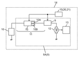
- FIG. 2 is a block diagram showing a door latch device 8A according to Embodiment 1 of the present invention.
- Door latch device 8A includes a latch motor connection switch 9, a converter line 11, a latch motor 12, and a latch 13.
- Converter line portion 11 is connected to the input side of latch motor connection switch 9 and has converter power supply portion 10.
- the latch motor 12 is connected to the output side of the latch motor connection switch 9 and is driven when the latch motor connection switch 9 is closed.
- the latch unit 13 is opened by driving the latch motor 12.
- the latch motor connection switch 9 is closed based on an instruction for opening the latch unit 13 by the user.
- converter power supply unit 10 is activated to boost the voltage input to converter power supply unit 10.
- the boosted voltage is output to the latch motor connection switch 9.
- latch unit 13 can normally operate. Therefore, the vehicle 14 does not have to have the mechanical opening operation function for emergency by providing only the door latch device 8A having the electric opening operation function for both normal use and emergency use. As a result, the vehicle 14 is reduced in weight.
- the door handles 20 and 21 may be considered as a type of switch.
- the user pulling on the door handle 20 corresponds to closing of a switch called the door handle 20, and in conjunction with this operation, the latch motor connection switch 9 is closed. That is, the operation of the user pulling the door handle 20 is an instruction for closing the latch motor connection switch 9.
- the door handle 20 instructs the converter power supply unit 10 to boost the terminal voltage of the vehicle battery (hereinafter, battery) 16. That is, the operation in which the user pulls the door handle 20 is an instruction for activating the converter power supply unit 10.
- the operation of boosting the terminal voltage of battery 16 by activation of converter power supply unit 10 is performed regardless of the value of the terminal voltage of battery 16.
- the boosted voltage value output from converter power supply unit 10 may be equal to or higher than the minimum voltage necessary to drive latch motor 12.
- the latch portion 13 can be opened by using the electric open operation function.
- the vehicle 14 there is no need to provide the vehicle 14 with a mechanical opening function for emergency use. That is, only the door latch device 8 capable of responding to both normal response and emergency response by the electric opening operation function is mounted on the vehicle 14, thereby reducing the weight of the vehicle 14 and the weight of the vehicle 14. Fuel efficiency can be improved.
- the electrical opening operation function can be activated unless the power supply from the battery 16 is completely stopped.
- the converter line portion 11 from the battery 16 to the converter power supply unit 10 is disconnected or the battery 16 is destroyed, the power supply from the battery 16 is completely stopped.
- the electrical opening function can be activated. Therefore, even if an accident occurs in the vehicle 14, the passenger can escape outside the vehicle by operating the door handle 21 on the indoor side. Furthermore, the third party can rescue the passenger from the cabin 19 to the outside of the vehicle by operating the door handle 20 from the outside of the vehicle 14 after the accident.
- the maintenance worker can enter and leave the vehicle 14 even when the battery 16 is out of order. Therefore, the worker can easily restore the vehicle 14 in order to replace the battery 16 or the like. Then, since converter power supply unit 10 operates only when door handle 20 is pulled, power is not constantly consumed in an idle state where vehicle 14 turns off the engine and completely stops the operation.
- converter power supply unit 10 and latch motor connection switch 9 will be described in detail.
- the converter power supply unit 10 receives an instruction from the door handle 20 for activating the converter power supply unit 10. Then, converter power supply unit 10 is activated using the power of battery 16 and measures the terminal voltage of battery 16.
- converter power supply unit 10 compares the measured value of the terminal voltage of battery 16 with the preset drivable voltage value of latch motor 12. Then, based on the comparison result, details of the step-up operation by converter power supply unit 10 and the opening / closing operation of latch motor connection switch 9 are determined.
- converter power supply unit 10 details of the boosting operation in converter power supply unit 10 may be determined based on the above comparison result. First, when the terminal voltage of battery 16 is higher than the drivable voltage value of latch motor 12 and converter power supply unit 10 determines that battery 16 is normal, converter power supply unit 10 does not need to be boosted. The part 10 makes a decision. Then, converter power supply unit 10 does not cause switching operation of boosting switching element 10A in converter power supply unit 10. As a result, converter power supply unit 10 exists as a simple conductor path, and the terminal voltage of battery 16 is supplied to latch motor connection switch 9 as it is.
- converter power supply unit 10 determines that the terminal voltage of battery 16 is low and battery 16 is abnormal lower than the drivable voltage value of latch motor 12, boosting by converter power supply unit 10 is necessary. Converter power supply unit 10 determines that it is. Then, converter power supply unit 10 causes switching circuit 10A in the converter power supply unit 10 to perform a switching operation. Thus, the terminal voltage of the battery 16 is boosted by the converter power supply unit 10 and supplied to the latch motor connection switch 9. Thus, in converter power supply portion 10, the operation period is limited including the comparison operation of the terminal voltage of battery 16 and the drivable voltage value of latch motor 12. Therefore, the power consumption which the battery 16 bears can be suppressed small.
- converter power supply portion 10 is limited to the boosting period and the boosting width so that the terminal voltage of battery 16 is boosted to the drivable voltage value of latch motor 12 only during the minimum necessary period for driving latch motor 12. To operate. For example, even if the door handle 20 is continuously pulled, the converter power supply unit 10 only has a period shorter than a period in which the door handle 20 issues an instruction to open the latch unit 13. It just works. Alternatively, the latch motor connection switch 9 may be closed only for a period shorter than a period in which the door handle 20 issues an instruction to open the latch portion 13. Thus, in converter power supply unit 10, the operation period is further shortened, including the comparison operation of the terminal voltage of battery 16 and the drivable voltage value of latch motor 12. Therefore, the power consumption borne by the battery 16 can be further reduced. As a result, even if the voltage of the battery 16 is lowered, the door latch device 8 can be repeatedly operated at many opportunities.
- converter power supply unit 10 controls the operation of boosting switching element 10A in accordance with the terminal voltage of battery 16 when it is determined that converter power supply unit 10 performs the boosting operation, and predetermined operation is performed. Output voltage.
- converter power supply unit 10 may operate boosting switching element 10A regardless of the terminal voltage of battery 16 and output the boosted voltage without setting it to a predetermined value. Either of the above operations may be selected according to the allowable range of the drivable voltage of the latch motor 12.
- converter power supply unit 10 may supply voltage equal to or higher than the lower limit voltage that latch motor 12 can drive to latch motor 12 by performing control for simple boosting. Further, when the upper limit value of the drivable voltage of latch motor 12 is low, converter power supply unit 10 may operate by defining the upper limit value of the output voltage. That is, converter power supply unit 10 does not output a predetermined voltage, but may output a voltage within a certain band between the upper limit voltage and the lower limit voltage that latch motor 12 can drive.
- converter power supply unit 10 supplies power to latch motor 12.
- converter power supply unit 10 closes latch motor connection switch 9 after determining that the output voltage of converter power supply unit 10 is within a predetermined range while outputting a voltage. Power may be supplied to the latch motor 12 in this manner.
- converter power supply unit 10 may operate for step-down. For example, when converter power supply unit 10 determines that the terminal voltage of battery 16 is sufficiently high and therefore requires step-down in converter power supply unit 10, switching operation of step-down switching element 10B performs switching operation. Outputs the voltage after step-down. Then, converter power supply unit 10 supplies the stepped-down voltage to latch motor 12 through latch motor connection switch 9.
- converter power supply unit 10 has both the function related to the boosting operation and the function related to the step-down operation, and in the case where the input voltage to converter power supply unit 10 is equal to or higher than the predetermined threshold
- the functions of converter power supply unit 10 are different.
- converter power supply unit 10 can limit the range of the output voltage by the step-up operation and step-down operation, and latch motor 12 can be appropriately operated.
- FIG. 3 is a time-series diagram showing an operating state of a vehicle and a door latch device 8A mounted on the vehicle.
- the curve of “Battery voltage” shows the fluctuation of the voltage of the battery 16 which is the main power supply.
- the curve of "instruction from the door handle” indicates a change in the maintenance of the open instruction or the closed state due to the door handle 20, 21 being pulled.
- the curve of “converter power supply unit output voltage” indicates the fluctuation of the output voltage of converter power supply unit 10.
- the curve of the "latch motor connection switch” shows the change of the open or closed state of the latch motor connection switch 9.
- the curve of "latch motor terminal voltage” shows the fluctuation of the terminal voltage of the latch motor 12.
- the curve of “Latch part operation” shows the change of the open state or the closed state in the latch part 13.
- the curve of "battery voltage” shows a state in which the voltage of the battery 16 drops when the vehicle is left over a long period of several weeks or several months as time elapsed on the horizontal axis.
- the output voltage of the converter power supply unit 10 is 10 V, which is the specified output value.
- This voltage is also an example of an appropriate value for driving the latch motor 12.
- Converter power supply unit 10 operates in response to the open instruction. However, since the terminal voltage of battery 16 is equal to or higher than the threshold value, when converter power supply unit 10 has only the boost function, converter power supply unit 10 outputs the terminal voltage of battery 16 as it is. On the other hand, when converter power supply unit 10 has a step-down function, converter power supply unit 10 outputs 10 V which is an output prescribed value.
- Converter power supply unit 10 operates in response to the open instruction. In this case, the converter power supply unit 10 boosts the terminal voltage of the battery 16 by the boosting function of the converter power supply unit 10 and outputs 10 V which is an output prescribed value.
- the curve of "latch motor connection switch”, the curve of "latch motor terminal voltage”, and the curve of “latch part operation” are the curve of "instruction from door handle” and the curve of "converter power supply output voltage"
- the instruction, the operation, and the on / off timing of the voltage also have a substantially identical shape.
- converter power supply unit 10 When converter power supply unit 10 operates to step up or step down, converter power supply unit 10 may operate in a minimum necessary period to drive latch motor 12. As described above, when the operation period is limited, the curve of "converter power supply output voltage", the curve of "latch motor connection switch”, the curve of "latch motor terminal voltage”, and the curve of "latch portion operation” are Each has a shape in which the period is shortened as shown by the broken line. That is, converter power supply unit 10 supplies power to latch motor 12 in a time shorter than the time for receiving an instruction for opening latch 13 from door handle 20.
- latch motor connection switch 9 may be connected for a time shorter than the time for receiving an instruction for opening latch 13 from door handle 20 without shortening the operation period of converter power supply 10.
- converter power supply 10 supplies power to latch motor 12 only for a time shorter than the open operation instruction.
- the curve of "latch motor terminal voltage" and the curve of "latch part operation” substantially correspond to the logical product of the curve of "converter power supply part output voltage” and the curve of "latch motor connection switch".
- converter power supply unit 10 compares the terminal voltage of battery 16 with a predetermined threshold in order to determine either the step-up operation or the step-down operation.
- the threshold value is 10 V
- the post-boost and post-buck correction values are also 10 V.
- these threshold values and correction values do not have to match.
- the threshold for determination regarding the boosting operation may be defined as 9 V
- the correction value after boosting may be defined as 9.5 V
- the sensitivity for the boosting operation may be reduced to reduce the width of boosting. This can further suppress the deterioration of the battery 16.
- FIG. 4 is a block diagram showing a door latch device 8B according to a second embodiment of the present invention.
- the door latch device 8B has a power supply line 22 and a controller 23 in addition to the configuration of the door latch 8A.
- the power supply line 22 connects the battery 16 and the input side of the latch motor connection switch 9. That is, converter line portion 11 and power supply line portion 22 are arranged in parallel connection.
- the control unit 23 is connected to the door handle 20. The other configuration is the same as the door latch device 8A. Then, control unit 23 controls the operation of converter power supply unit 10.
- the open / close instruction unit 15 instructs the latch unit 13 to open
- the latch motor connection switch 9 is closed.
- power is supplied from the battery 16 to the latch motor 12 through the converter power supply 10 or the power supply line 22.
- converter power supply unit 10 is activated as necessary, and converter power supply unit 10 boosts the voltage supplied from battery 16 to converter power supply unit 10.
- the latch portion 13 can be normally opened. Therefore, it is not necessary to provide the mechanical opening operation function for emergency by using only the door latch device 8 having the electric opening operation function for both normal use and emergency use, and the weight of the door latch device 8 and the vehicle 14 can be reduced. it can. That is, only the door latch device 8 having the electrical opening operation function is mounted on the vehicle 14, and even if the voltage of the battery 16 drops, the user can enter and exit the vehicle 14, and escape from the vehicle in an emergency or The response to the vehicle 14 including the replacement of the vehicle 16 becomes easy. In addition to this, the fuel efficiency of the vehicle 14 can be improved.
- the door latch device 8 B has a parallel path of the converter line portion 11 and the power supply line portion 22 in order to supply power to the latch motor 12. Therefore, when vehicle 14 encounters any accident, battery 16 can continue the power supply to latch motor 12 if either converter line 11 or power supply line 22 is normal.
- Door latch device 8 B includes a latch motor connection switch 9, a converter line 11, a latch motor 12, a latch 13, a power line 22, and a controller 23.
- Converter line portion 11 is connected to the input side of latch motor connection switch 9 and has converter power supply portion 10.
- the latch motor 12 is connected to the output side of the latch motor connection switch 9 and is driven when the latch motor connection switch 9 is closed.
- the latch unit 13 is opened by driving the latch motor 12.
- the power supply line 22 is connected to the input side of the latch motor connection switch 9 and is connected in parallel to the converter line 11.
- Control unit 23 is connected to power supply line 22 and converter power supply 10.
- converter power supply unit 10 is provided in converter line portion 11, and battery 16 is a latch motor via converter line portion 11 and latch motor connection switch 9 or a power supply line portion 22 and latch motor connection switch 9. Supply power to 12
- the user issues an instruction to open the latch unit 13.
- the door handle 20 from the outside of the vehicle 14 or pulls the door handle 21 from within the compartment 19 to instruct the latch unit 13 to be in the open state. Therefore, the door handles 20 and 21 may be considered as a kind of switch.
- the user pulling on the door handle 20 corresponds to closing of a switch called the door handle 20, and in conjunction with this operation, the latch motor connection switch 9 is closed. That is, the operation of the user pulling the door handle 20 is an instruction for closing the latch motor connection switch 9.
- the control unit 23 instructs the converter power supply unit 10 to boost the terminal voltage of the battery 16. That is, the operation of pulling the door handle 20 by the user causes the control unit 23 to be activated, and the control unit 23 instructs the converter power supply unit 10 to be activated.
- Control unit 23 starts the operation in response to the user pulling on door handle 20, controls the operation of converter power supply unit 10, and detects the voltage value of each of converter power supply unit 10 and power supply line unit 22. At this time, the control unit 23 particularly detects the voltage value of the power supply line portion 22 and compares the detected voltage with a predetermined threshold value to determine whether the battery 16 is in a normal state or in an abnormal state. Determine if there is.
- control portion 23 keeps converter power supply portion 10 stopped without being activated.
- the battery 16 does not supply power to the latch motor connection switch 9 via the converter power supply unit 10.
- This state corresponds to a state in which the terminal voltage of the battery 16 is normal and the battery 16 is not accompanied by deterioration or damage.
- control portion 23 activates converter power supply portion 10.
- the battery 16 supplies power to the latch motor connection switch 9 through the converter power supply unit 10.
- the predetermined threshold value here may be defined on the basis of a voltage value capable of driving the latch motor 12.
- the control unit 23 detects and operates, and then the latch motor connection switch 9 may be controlled to be closed.
- the operation of closing the latch motor connection switch 9 may be controlled by the door handle 20 at the same time as the door handle 20 is pulled.
- the door latch device 8 can open the latch portion 13 using the electric open operation function. For this reason, it is not necessary to provide the vehicle with an emergency mechanical opening operation function. Therefore, by mounting on the vehicle only the door latch device 8B having the electrical opening operation function having both the normal response and the emergency response, it is possible to reduce the weight of the vehicle and to improve the fuel consumption.
- the door latch device 8B when the battery 16 is normal, that is, in most of the period in which the vehicle 14 is operating, the battery 16 supplies power using the power supply line 22 where no electrical element exists.
- a diode (not shown) may be connected to the power supply line 22 with the battery 16 side as the cathode side in order to prevent reverse current, but when the diode operates in the forward direction, Although a voltage drop occurs, a large power loss does not occur. Thereby, when the battery 16 is normal, the loss of power can be minimized. As a result, the door latch device 8B can suppress the deterioration of the battery 16.
- converter power supply unit 10 stops the operation with a large power consumption. Therefore, the deterioration of the battery 16 can be suppressed also at this point.
- the control unit 23 detects the voltage value of the power supply line portion 22, but the control unit 23 may detect the voltage value of the input end of the latch motor connection switch 9. As a result, the control unit 23 can detect an abnormality that has occurred in all parts of the power supply line portion 22. That is, the control unit 23 can detect an abnormality occurring on the battery 16 side of the latch motor connection switch 9 over a wide range.
- the switching element 24 may be disposed between the output side of the converter power supply unit 10 and the latch motor connection switch 9. That is, converter power supply unit 10 and switching element 24 may be arranged in converter line portion 11A. Switching element 24 is arranged in series on the output side of converter power supply unit 10.
- the control unit 23 activates the converter power supply 10 and controls the switching element 24 to be in the cut-off state.
- the battery 16 does not supply power to the latch motor connection switch 9 via the converter power supply unit 10. This applies to a state where the terminal voltage of the battery 16 is normal and the battery 16 is not accompanied by deterioration or damage.
- control unit 23 controls converter power supply 10 to be activated.
- control unit 23 controls switching element 24 to switch from the cutoff state to the connection state.
- the battery 16 supplies power to the latch motor connection switch 9 via the converter power supply unit 10. This is applied when the terminal voltage of the battery 16 is abnormal and the battery 16 is in a state accompanied by deterioration or damage.
- the predetermined threshold value may be defined on the basis of a voltage value capable of driving the latch motor 12 as in the case described above.
- control unit 23 compares the voltage detected by the power supply line 22 with a preset threshold value. When control unit 23 determines that the voltage detected at power supply line unit 22 is lower than the threshold, control unit 23 instructs converter power supply unit 10 to start the boosting operation, and the switching element 24 is controlled to switch from the disconnected state to the connected state. Then, based on an instruction from the door handle 20, the latch motor connection switch 9 is closed. Thus, the voltage boosted by converter power supply unit 10 is supplied to latch motor connection switch 9 and latch motor 12.
- a reverse current prevention element (not shown) may be disposed in the power supply line portion 22.
- the reverse current preventing element may be opened in synchronization with the operation of converter power supply unit 10.
- the reverse current prevention element may be released after control unit 23 instructs converter power supply unit 10 to start the boosting operation and before the boosting operation of converter power supply unit 10 starts.
- FIG. 6 is a time-series diagram showing an operating state of the vehicle and the door latch device 8B or the door latch device 8C mounted on the vehicle. Each curve shows the same contents as in FIG.
- Converter power supply unit 10 operates in response to the open instruction. However, when the terminal voltage of battery 16 is equal to or higher than the threshold value, converter power supply unit 10 does not output a voltage.
- Converter power supply unit 10 operates in response to the open instruction. Then, the boosting function of converter power supply unit 10 operates, and converter power supply unit 10 boosts the terminal voltage of battery 16 to output 10 V which is an output prescribed value.
- the door latch devices 8B and 8C can be repeatedly operated at many opportunities.
- converter power supply unit 10 of the door latch devices 8B and 8C described here has the step-up operation function, it may have the function of both the step-up operation and the step-down operation.
- converter power supply unit 10 compares the terminal voltage of battery 16 with a predetermined threshold to determine either the boosting operation or the bucking operation. Further, as shown in FIG. 6, this threshold value is 10 V, and the post-boost and post-buck correction values are also 10 V. However, there is no need to make the correction values match these thresholds.
- the door latch devices 8A, 8B and 8C described in the first and second embodiments can operate when the battery 16 is deteriorated.
- the door latch device 8D described below can operate even when the battery 16 can not be discharged due to damage or the like.
- FIG. 7 is a block diagram showing a door latch device 8D according to a third embodiment of the present invention.
- the door latch device 8D includes a latch motor connection switch 9, a converter line portion 11B, a latch motor 12, a latch portion 13, a power supply line portion 22, and a control portion 23.
- the latch motor connection switch 9 is opened and closed by an instruction from an open / close instruction unit 15 provided in the vehicle 14.
- Converter line portion 11 B connects battery 16 arranged in vehicle 14 to the input side of latch motor connection switch 9.
- Converter line portion 11 B includes a converter power supply portion 110 and an interlock switch 25.
- the latch motor 12 is connected to the output side of the latch motor connection switch 9. Furthermore, the battery 16 and the input side of the latch motor connection switch 9 are connected by the power supply line 22.
- converter line portion 11B and power supply line portion 22 are connected in parallel.
- the control unit 23 is connected to the door handle 20. Then, control unit 23 detects the voltage of power supply line 22 and controls the operation of converter power supply 110.
- the latch unit 13 is opened by driving the latch motor 12 when the latch motor connection switch 9 is closed. Therefore, when the open / close instruction unit 15 instructs to open the latch unit 13, the latch motor connection switch 9 is closed. Then, power is supplied to latch motor 12 from converter power supply 110 or through power supply line 22. Then, converter power supply unit 110 is activated as required, and is supplied from converter power supply unit 110 to latch motor 12.
- the operation when the door latch device 8D is mounted on the vehicle 14 is shown as an example. Therefore, the operation of the door latch device 8D is based on when the interlock switch 25 or the engine switch 26 of the vehicle 14 is switched from OFF to ON or is ON. If the door latch device 8D operates alone, the operation of the door latch device 8D is based on the time when the power supply instruction to the converter power supply unit 110 is turned from OFF to ON, or when it is ON. And it is sufficient.
- converter power supply unit 110 has a storage function, and when engine switch 26 of vehicle 14 is turned on, converter power supply unit 110 internally starts charging.
- the control unit 23 when the engine switch 26 of the vehicle 14 is ON, the control unit 23 always detects the voltage value of the power supply line 22 and the control unit 23 compares the power supply line 22 with a predetermined threshold.
- the converter power supply 110 continues to operate. That is, converter power supply unit 110 continues boosting and charging.
- control unit 23 may control the operation of converter power supply unit 110.
- the power supply line 22 supplies power from the battery 16 to the latch motor connection switch 9.
- the control unit 23 determines that the power supply from the battery 16 is in a normal state.
- converter power supply portion 110 stops its operation and is put into the inactive state to boost the voltage. Stop charging. Thereafter, when the user instructs the door handle 20 to perform the opening operation and the door latch device 8D receives the instruction for opening the latch portion 13, the latch motor connection switch 9 is closed. At the same time, converter power supply unit 110 shifts from the stopped state to the operating state, starts the operation again, and supplies power to latch motor 12 through latch motor connection switch 9. That is, converter power supply unit 110 resumes boosting and charging. However, since the input voltage to converter power supply 110 is low or absent, converter power supply 110 is hardly charged in practice. At this time, since the voltage of the power supply line portion 22 is lower than the threshold, the control unit 23 determines that the power supply from the battery 16 is in an abnormal state.
- the latch portion 13 can be opened by only the electrical opening function as in the first embodiment.
- the vehicle 14 there is no need to provide the vehicle 14 with a mechanical opening function for emergency use. That is, only the door latch device 8D capable of responding to both normal response and emergency response by the electric opening operation function is mounted on the vehicle 14, thereby reducing the weight of the vehicle 14 and accordingly improving the fuel consumption. Is possible.
- the power supply from the battery 16 is interrupted particularly when the battery 16 is damaged or when the power supply line 22 is disconnected. Even in such a case, the electric open operation function can be activated by using the power stored in converter power supply unit 110.
- the third party can rescue the passenger from the cabin 19 to the outside of the vehicle by operating the door handle 20 from the outside of the vehicle 14 after the accident.
- the door latch device 8D includes a latch portion 13, a latch motor 12, a latch motor connection switch 9, a converter line portion 11B, and a power supply line portion 22 connected in parallel to the converter line portion 11B.
- the interlock switch 25 interlocked with the engine switch 26 and the converter power supply 110 are connected in series and arranged in the converter line 11B.
- the battery 16 supplies power to the latch motor 12 through the converter line portion 11 B and the latch motor connection switch 9 or through the power supply line portion 22 and the latch motor connection switch 9.
- the user issues an instruction to open the latch unit 13.
- the user pulls the door handle 20 from the outside of the vehicle 14 or pulls the door handle 21 from within the compartment 19 to open the latch portion 13.
- the door latch device 8D operates in the following order to open the latch portion 13. First, the user pulls on the door handle 20 to activate the control unit 23. Next, the control unit 23 detects the voltage value of the power supply line 22 and compares the detected voltage with a predetermined threshold to determine whether the battery 16 is in a normal state or in an abnormal state. judge.
- the battery 16 supplies power to the latch motor connection switch 9 and the latch motor 12 through the power supply line 22. Then, although converter power supply unit 110 operates, it does not output power, or outputs weak power of low current and low current.
- the operation in the case where the voltage value of the power supply line portion 22 is equal to or higher than a predetermined threshold value is substantially the same when the interlock switch 25 interlocked with the engine switch 26 and the engine switch 26 is ON and OFF.
- converter power supply unit 110 continues to operate for charging, and does not output power or outputs weak power.
- converter power supply unit 110 includes charge circuit 27, discharge circuit 29 and storage element 28.
- the discharge circuit 29 is connected to the latch motor connection switch 9, the charge circuit 27 is connected in series to the discharge circuit 29, and one end of the storage element 28 is connected to the connection point between the charge circuit 27 and the discharge circuit 29. .
- converter power supply 110 starts charging and discharging. That is, control unit 23 operates charging circuit 27 of converter power supply unit 110 for charging to charge storage element 28, and operates discharging circuit 29 at a low duty ratio for discharging to set storage element 28. Consume power. At this time, the output current from the discharge circuit 29 is approximately 0A. The above corresponds to a state in which the terminal voltage of the battery 16 is normal and the battery 16 is not accompanied by deterioration or damage.
- the operation of the door latch device 8D differs depending on the state of the engine switch 26.
- This state corresponds to, for example, the case where the terminal voltage of the battery 16 is lowered due to the vehicle 14 being left for a long time.
- the control unit 23 is activated by the door handle 20 being pulled. Then, the control unit 23 determines that the voltage of the battery 16 is lowered based on the result of comparison between the power supply line portion 22 and the predetermined threshold value. Next, control unit 23 causes discharge circuit 29 to boost the power stored in storage element 28. Then, the boosted voltage is supplied to the latch motor 12 through the closed latch motor connection switch 9, and the latch unit 13 is opened.
- the door latch device 8D can open and close the door 18 only by the electric opening operation function without using the mechanical opening operation function.
- a state in which a sharp drop occurs in the voltage of the power supply line portion 22 while the vehicle 14 is operating is, for example, a state where the instruction of the engine switch 26 is ON and the vehicle 14 is operating suddenly. This corresponds to, for example, the case where the terminal voltage of the battery 16 is lowered and the operation of the vehicle 14 is stopped. That is, for example, when the vehicle 14 encounters an accident and the battery 16 falls into a serious situation.
- control unit 23 determines that the vehicle 14 and the battery 16 are in an emergency based on the result of comparison between the power supply line 22 and the predetermined threshold.
- the control unit 23 stops the operation of the converter power supply unit 110. That is, control unit 23 stops the operation of charging circuit 27 and stops the operation of discharging circuit 29 to control converter power supply 110 in a state in which the power stored in storage element 28 is maintained.
- the stop state of converter power supply unit 110 is a temporary stop. That is, converter power supply unit 110 is ready to be restarted immediately upon receiving an instruction from control unit 23.
- control unit 23 receives supply of power from storage element 28 that enables operation such as calculation by control unit 23, and can operate regardless of the terminal voltage of battery 16. Therefore, when the terminal voltage of the battery 16 is normal, the battery 16 bears the power supply to the control unit 23, and when the terminal voltage of the battery 16 is detected as abnormal, the converter power supply unit 110 bears it. Then, when the passenger or a rescuer outside the vehicle pulls the door handle 21 or the door handle 20, the control unit 23 instructs the converter power supply unit 110 to restart.
- Converter power supply portion 110 including storage element 28 and discharge circuit 29 boosts the power stored in storage element 28 by discharge circuit 29 based on the instruction from control section 23, and supplies it to latch motor 12 through latch motor connection switch 9. Do.
- the power for activating control unit 23, the power for opening and closing latch motor connection switch 9, and the power for activating converter power supply unit 110 are such that the voltage value of power supply line 22 is higher than a predetermined threshold value Alternatively, it can be supplied by the battery 16 or the storage element 28 in order to be able to cope with the low case.
- the power stored in storage element 28 of converter power supply portion 110 is boosted by discharge circuit 29 except for the weak power applied to maintain the function of control portion 23, and then the latch motor 12 is generated. Can be supplied.
- door latch device 8D discharges latch motor 12 only when converter power supply 110, which has stored emergency power when the vehicle 14 enters an emergency and loses power, is instructed from door handle 20. to start. Therefore, the door latch device 8D can be opened not only immediately after the accident but also can be opened continuously or intermittently.
- the rescuer can latch the door latch from the outside of the vehicle 14 8D can be opened not only once but repeatedly.
- the control unit 23, the converter power supply unit 110, the latch motor connection switch 9, the latch motor 12, and the latch unit 13 may be concentrated in the door 18 to be opened. That is, all the connectors 30 which are conductors connecting the individual functional elements in the door latch device 8D may be made shorter than the power supply line portion 22 which is a normal power supply path.
- the door latch device 8D can be reduced in size and weight, and operates in response to an emergency such as an accident. Therefore, even if the vehicle 14 encounters an accident, the door latch device 8D has a short connection body 30 and therefore is less likely to be damaged such as a disconnection, and in particular, the operation reliability of the converter power supply 110 is improved. That is, the door latch device 8D can easily maintain its function by reducing the possibility of damage in the connector 30 than the possibility of damage in the power supply line portion 22.
- the door latch device 8D can cope with the normal time and the emergency time by the electric opening operation, and the door latch device 8D can be miniaturized and reduced in weight.
- the door latch 8D can be located anywhere in the door 18.
- the door 18 may be disposed at a biased position on the hinge side.
- the door latch device 8D may be disposed at a position at which the door 18 is subjected to an appropriate moment.
- the control unit 23 determines that the terminal voltage of the battery 16 suddenly falls and the vehicle 14 encounters an accident when the vehicle 14 is in operation with the engine switch 26 ON, the passenger or When the rescuer operates the door handle 20, the latch unit 13 may be opened, and the window 31 disposed close to the latch unit 13 may be opened. As a result, the number of routes for the passenger to leave the vehicle 14 increases, and the rescuer can rescue the passenger from the vehicle 14 more reliably.
- FIG. 8 is a time-series diagram showing an operation state of a vehicle and a door latch device 8D mounted on the vehicle.
- the curve of "the engine switch of the vehicle” shows the change of the instruction state about the start and stop from the engine switch 26 to the vehicle 14, and the curve of the "converter power supply output voltage” shows the fluctuation of the output voltage of the converter power supply 110 ing.
- the other curves are the same as in FIG.
- period A indicates the timing when the engine switch 26 switches from OFF to ON
- period C indicates the timing when the engine switch 26 switches from ON to OFF.
- the period A corresponding to the period before the user activates the vehicle 14 will be described. Although the timing at which the period A starts is not shown here, this timing is a timing at which the vehicle 14 is stopped in the correct procedure at the previous use.
- the control unit 23 Since engine switch 26 is in the OFF state, vehicle 14 is not operating in period A.
- the control unit 23 is activated to detect the voltage of the power supply line 22. Then, the control unit 23 compares this voltage with a predetermined threshold.
- the predetermined threshold may be set as a value that does not fall below the battery 16 as long as there is no abnormality.
- the predetermined threshold is shown as 6V. In period A, since the voltage of the battery 16 is normal 12 V and higher than the threshold, the control unit 23 determines that the battery 16 is normal.
- the power of the battery 16 is supplied to the latch motor 12 through the power supply line 22.
- control unit 23 controls converter power supply unit 110 not to operate.
- both the terminal voltage of the battery 16 and the terminal voltage of the latch motor 12 are approximately 12 V.
- the vehicle 14 By switching the engine switch 26 from OFF to ON, the vehicle 14 is activated. Further, the control unit 23 is activated in response to the activation of the vehicle 14.
- the control unit 23 always detects the voltage of the power supply line 22 while the engine switch 26 is in the ON state, that is, while the engine switch 26 is in the ON position. Then, the control unit 23 constantly compares the voltage of the power supply line 22 with the threshold value. In period B, since the voltage of the battery 16 is normal 12 V and higher than the threshold, the control unit 23 determines that the battery 16 is normal.
- converter power supply unit 110 is also activated in response to activation of vehicle 14.
- the charging circuit 27 of the converter power supply unit 110 operates to charge the storage element 28 to a fully charged state or a state close thereto.
- discharge circuit 29 of converter power supply 110 discharges part of the power stored in storage element 28, and converter power supply 110 outputs small power.
- the voltage output from converter power supply unit 10 is lower than the voltage of battery 16, and in particular lower than the threshold.
- the output current from converter power supply 110 can be prevented from flowing back into power supply line 22 and entering.
- the output current from converter power supply unit 110 is a minute current. That is, the discharge circuit 29 operates by switching with low on-duty.
- control unit 23 or converter power supply unit 10 may control discharge circuit 29 in this manner.
- the output voltage from converter power supply unit 110 is lower than the voltage of battery 16 is shown here as an example, even if the output voltage from converter power supply unit 110 is equal to the voltage of battery 16, or Above, it may be less than the voltage of the battery 16.
- a diode (not shown) may be connected to the power supply line 22 with the battery 16 side as the cathode side, and a reverse flow prevention function may be provided. In this case, when the diode operates in the forward direction, although a slight voltage drop occurs due to the forward voltage, no large power loss occurs.
- control unit 23 may detect the minute power of the weak current continuously or intermittently at the low voltage of the discharge circuit 29. Thus, it can be determined whether or not converter power supply unit 110 can operate normally.
- Control unit 23 controls converter power supply unit 110 to operate.
- converter power supply 110 outputs a weak current at a voltage lower than 6 V which is a threshold. Since the voltage of the battery 16 is supplied to the latch motor 12 as it is, both of the terminal voltage of the battery 16 and the terminal voltage of the latch motor 12 are approximately 12 V. Thus, when the user operates the door handle 20 in period B, the latch unit 13 is opened.
- converter power supply unit 110 continues the discharging operation by discharging circuit 29 in period B, and this operation ends in the middle of period C. Also, this duration may have a range of several minutes to several tens of minutes.
- control unit 23 estimates the capacity of storage element 28 from the constants of storage element 28, and control unit 23 further determines the discharge period of discharge circuit 29 based on the estimation result. Should be set.
- the storage element 28 has been described using an electric double layer capacitor, but the storage element 28 may be a secondary battery such as a lithium ion battery.
- the operating characteristics of converter power supply 110 are determined in accordance with the characteristics of storage element 28.
- the vehicle 14 By switching the engine switch 26 from OFF to ON, the vehicle 14 is activated. Further, in response to activation of the vehicle 14, the control unit 23 is activated, and the control unit 23 always keeps the voltage of the power supply line 22 while the engine switch 26 is in the ON state, ie, while the engine switch 26 is in the ON position. Detect Then, the control unit 23 constantly compares the voltage of the power supply line 22 with the threshold value. In period D, since the voltage of the battery 16 is normal 12 V and higher than the threshold, the control unit 23 determines that the battery 16 is normal. These operations and the operation of converter power supply unit 110 are the same as those described in period B. For example, the period D is a state in which the vehicle 14 is traveling or at rest because the engine switch 26 is turned ON.
- period E a period after the vehicle 14 encounters an accident or the like will be described.
- battery 16 and converter power supply 110 operate normally during period D described above, vehicle 14 encounters an emergency such as an accident and vehicle 14 loses power supply from battery 16.
- the period E corresponds to the time when the vehicle 14 loses the power supply from the battery 16 and the state thereafter.
- the control unit 23 Since the vehicle 14 is in operation and the instruction of the engine switch 26 is in the ON state, the control unit 23 already in operation detects the voltage of the battery 16. Furthermore, the control unit 23 determines that the vehicle 14 or the battery 16 is in an emergency state because the voltage is lower than the threshold. That is, the control unit 23 determines that the vehicle 14 is abnormal because the voltage of the battery 16 rapidly decreases even though the vehicle 14 is in the operating state by the normal startup.
- control unit 23 stops the operation of converter power supply unit 110 based on the above determination.
- the operations of charging circuit 27 and discharging circuit 29 are stopped, and discharging circuit 29 can be restarted immediately by an instruction from control unit 23 later. It is in the state of As described above, since the operation of charging circuit 27 and discharging circuit 29 is stopped, most of the power stored in storage element 28 is maintained in storage element 28. A part of the power stored in storage element 28 is used to maintain the operation of control unit 23 or to maintain the control function of converter power supply unit 110. The power required to maintain these operations and functions is very small. Therefore, these operations and functions can be continued for a long time.
- control unit 23 instructs converter power supply unit 110 to restart.
- Converter power supply unit 110 including storage element 28 and discharge circuit 29 boosts the power stored in storage element 28 by discharge circuit 29 based on an instruction from control unit 23.
- converter power supply unit 110 supplies power to latch motor 12 through latch motor connection switch 9.
- the boosting operation in the discharge circuit 29 is different from the operation in the period B, and the boosted voltage must be at a level at which the latch motor 12 can operate.
- the power supply line 22 corresponds to a disconnected state.
- the boosted voltage is not applied to the input side of converter power supply 110 regardless of whether or not the diode for preventing the backflow described above is connected.
- the discharge circuit 29 operates by switching with a high on-duty ratio as compared to the operation in the period B.
- the latch motor 12 requires a large amount of power to drive. Therefore, the current output from converter power supply 110 may be a large value compared to the current in period B, not a weak current.
- the door latch device 8D can realize size reduction and weight reduction, and can be operated in an unexpected situation. Therefore, the reliability of the operation of the door latch device 8D can be improved by reducing the device having the switching function for selecting the power supply path.
- Converter power supply 110 may operate only when door handle 20 or door handle 21 is operated. That is, the discharge circuit 29 may boost and output the power stored in the storage element 28 only when the output of the power is required.
- the door latch device 8D can be opened not only immediately after the vehicle 14 encounters an accident, but also can be continuously opened and intermittently repeated. That is, even if the vehicle 14 encounters an accident and the battery 16 falls into a serious situation, and a situation requiring a great deal of time from the accident to the rescue of the passenger, the rescuer can latch the door latch from the outside of the vehicle 14 8D can be opened not only once but repeatedly.
- the door latch device 8D can enhance the certainty regarding rescue.
- the closing period of the latch motor connection switch 9 may coincide with the period in which the door handle 20 is pulled to open the latch portion 13.
- the latch motor connection switch 9 may be set to remain closed while the voltage of the battery 16 suddenly drops and falls below the threshold although the engine switch 26 is in the ON state.
- a period in which the voltage of the battery 16 suddenly drops and falls below the threshold although the engine switch 26 is in the ON state corresponds to an emergency situation. Therefore, the reliability of the door latch device 8D can be improved by reducing the operation related to opening and closing as much as possible in this period.
- the latch motor connection switch 9 may be set to be closed after the above-described predetermined time has elapsed and the voltage of the battery 16 is below the threshold.
- the door latch device 8D can accurately grasp and operate that the decrease in the voltage of the battery 16 is not a temporary situation but an emergency situation. Further, during this period, the reliability of the door latch device 8 can be improved by minimizing the operation related to opening and closing.
- the operation of the door latch device 8D includes the battery 16, the interlock switch 25, and the engine switch 26.
- the battery 16 is disposed at any position of the vehicle 14 and is disposed outside the door latch device 8.
- the engine switch 26 is disposed at any position of the vehicle 14 and is disposed outside the door latch device 8D.
- the interlock switch 25 may be either inside or outside the door latch device 8D.
- interlock switch 25 is illustrated, this portion may be short-circuited without arranging the interlock switch 25.
- the determination reference of the state of the vehicle 14 by the control unit 23 of the door latch device 8D applies the voltage of the power supply line 22 corresponding to the voltage of the battery 16 and the state of the engine switch 26.
- the interlock switch 25 interlocks with the on / off of the engine switch 26 to switch on / off.
- the door latch device 8D uses the engine switch 26 as a reference. Therefore, the portion of the interlock switch 25 may be short-circuited.
- the door latch devices 8A to 8D have the electric opening operation function capable of coping with the normal condition or the emergency condition of the vehicle 14.
- a mechanical opening operation function may be additionally arranged as a second emergency door latch function.
- the door latch device 8 having the electrical opening operation function is small and light, the weight of the vehicle 14 does not significantly increase even if the mechanical opening operation function is added, and safety can be improved. .
- the second emergency door latch function having the mechanical opening operation function does not have to be provided on all the doors 18, and may be provided only on the frequently used doors. Further, the door latch devices 8A to 8D may be provided on the back door (not shown), the trunk door (not shown), and the fuel supply port cover (not shown). This allows the user to take out an emergency package or tool or discharge unnecessary fuel.
- control unit 23 is shown as an independent single circuit or element having various functions.
- control unit 23 may be included in the latch motor connection switch 9 or the converter power supply unit 110 and the like, and the functions of the control unit 23 described above may be distributed and provided as necessary.
- the vehicle 14 provided with the door latch devices 8A to 8D has been described.
- the door latch devices 8A to 8B are not limited to vehicles, but include mobile devices such as ships for transportation such as ships. It can apply.
- the latch portion can be normally opened even when the voltage of the battery decreases. Therefore, by using only the door latch device having the electrical opening operation function for both normal use and emergency use, the weight of the vehicle can be reduced and the fuel consumption of the vehicle can be reduced. Therefore, as a door latch device used for various vehicles It is valid.
Abstract
Description
図2は本発明の実施の形態1によるドアラッチ装置8Aを示すブロック図である。
図4は本発明の実施の形態2によるドアラッチ装置8Bを示すブロック図である。ドアラッチ装置8Bは、ドアラッチ装置8Aの構成に加え、電源路線部22と制御部23を有する。電源路線部22は、バッテリー16とラッチモータ接続スイッチ9の入力側とを接続する。つまり、コンバータ路線部11と電源路線部22とは並列接続で配置されている。また、制御部23はドアハンドル20に接続されている。これ以外の構成はドアラッチ装置8Aと同じである。そして制御部23はコンバータ電源部10の動作を制御する。開閉指示部15がラッチ部13を開動作させるための指示をすると、ラッチモータ接続スイッチ9が閉じられる。そして、バッテリー16からコンバータ電源部10もしくは電源路線部22を通じて、ラッチモータ12へ電力が供給される。またこのとき、コンバータ電源部10が必要に応じて起動し、バッテリー16からコンバータ電源部10へと供給された電圧をコンバータ電源部10が昇圧する。
実施の形態1、2で説明したドアラッチ装置8A、8B、8Cは、バッテリー16が劣化した場合に動作が可能である。以下で説明するドアラッチ装置8Dは、バッテリー16が破損などにより放電できなくなった場合にも動作することができる。
9 ラッチモータ接続スイッチ
10,110 コンバータ電源部
10A 昇圧用スイッチング素子
10B 降圧用スイッチング素子
11,11A,11B コンバータ路線部
12 ラッチモータ
13 ラッチ部
14 車両
15 開閉指示部
16 車両用バッテリー(バッテリー)
17 ボディー
18 ドア
19 車室
20,21 ドアハンドル
22 電源路線部
23 制御部
24 切り替え素子
25 連動スイッチ
26 エンジンスイッチ
27 充電回路
28 蓄電素子
29 放電回路
30 接続体
31 ウインドウ
Claims (12)
- ラッチモータ接続スイッチと、
前記ラッチモータ接続スイッチの入力側に接続されたコンバータ電源部を有するコンバータ路線部と、
前記ラッチモータ接続スイッチの出力側に接続され、前記ラッチモータ接続スイッチが閉じられた時に駆動するラッチモータと、
前記ラッチモータが駆動することで開動作されるラッチ部とを備え、
前記ラッチ部を開動作させるための指示に基づき、前記ラッチモータ接続スイッチが閉じるとともに、前記コンバータ電源部が起動して前記コンバータ電源部への入力電圧を昇圧して前記ラッチモータ接続スイッチへ出力するドアラッチ装置。 - 前記コンバータ電源部は、前記ラッチ部を開動作させるための指示を受ける期間よりも短い期間で前記ラッチモータへと電力を供給する、
請求項1に記載のドアラッチ装置。 - 前記コンバータ電源部は昇圧動作機能および降圧動作機能を有し、
前記コンバータ電源部への前記入力電圧が閾値以上であるときは前記コンバータ電源部は降圧動作し、
前記コンバータ電源部への前記入力電圧が前記閾値よりも低いときは前記コンバータ電源部は昇圧動作する、
請求項1に記載のドアラッチ装置。 - 前記ラッチモータ接続スイッチの入力側に接続されるとともに前記コンバータ路線部に並列接続された電源路線部と、
前記電源路線部の電圧を検知して、前記コンバータ電源部を起動させる制御部と、をさらに備えた、
請求項1に記載のドアラッチ装置。 - 前記電源路線部の電圧が閾値よりも低下した状態で前記ラッチ部を開動作させるための指示が行われた場合に、
前記ラッチ部を開動作させるための指示に基づき前記ラッチモータ接続スイッチが閉じるとともに、
前記制御部の指示に基づき前記コンバータ電源部が起動する、
請求項4に記載のドアラッチ装置。 - 前記コンバータ電源部は蓄電機能を有し、前記コンバータ電源部への電力供給指示がONとなることで前記コンバータ電源部は充電を開始し、
その後に前記コンバータ電源部への前記電力供給指示がONとなっている状態で前記電源路線部の電圧が閾値以上である場合は前記コンバータ電源部が継続して動作するとともに、前記電源路線部が前記ラッチモータ接続スイッチへと電力を供給し、
前記コンバータ電源部への前記電力供給指示の指示がONとなっている状態で前記電源路線部の電圧が閾値未満となった場合は前記コンバータ電源部は動作停止し、その後に前記ラッチ部を開動作させるための指示を受け、前記ラッチモータ接続スイッチが閉じるとともに前記コンバータ電源部が停止から動作へと移行して前記コンバータ電源部は前記コンバータ電源部に充電された電力を昇圧して前記ラッチモータへ供給する、
請求項4に記載のドアラッチ装置。 - 前記コンバータ電源部は、
前記ラッチモータ接続スイッチに接続された放電回路と、
前記放電回路に直列接続された充電回路と、
前記充電回路と前記放電回路との接続点に一端を接続された蓄電素子と、を有する、
請求項6に記載のドアラッチ装置。 - 前記コンバータ電源部への前記入力電圧からの電力供給が正常状態で前記コンバータ電源部への前記電力供給指示をOFFにして前記車両を停止した場合は、前記車両の停止後にも前記放電回路は所定の期間に動作継続する、
請求項6に記載のドアラッチ装置。 - 前記ラッチモータ接続スイッチの入力側に接続されるとともに前記コンバータ路線部に並列接続された電源路線部と、
前記ラッチモータ接続スイッチの前記入力側の電圧を検知して前記コンバータ電源部を起動させる制御部と、をさらに備えた、
請求項1に記載のドアラッチ装置。 - 前記ラッチモータ接続スイッチの前記入力側の電圧が閾値よりも低下した状態で前記ラッチ部を開動作させるための指示が行われた場合に、
前記ラッチ部を開動作させるための指示に基づき前記ラッチモータ接続スイッチが閉じるとともに、
前記制御部の指示に基づき前記コンバータ電源部が起動する、
請求項9に記載のドアラッチ装置。 - 本体と、
前記本体に設けられたドアと、
前記ドアに配置されたドア開閉指示部と、
前記本体に設けられたバッテリーと、
ラッチモータ接続スイッチと、
前記バッテリーと前記ラッチモータ接続スイッチの入力側とを接続するコンバータ電源部を有するコンバータ路線部と、
前記ラッチモータ接続スイッチの出力側に接続され、前記ラッチモータ接続スイッチが閉じられた時に駆動するラッチモータと、
前記ラッチモータが駆動することで開動作されるラッチ部と、を備え、
前記ドア開閉指示部から前記ラッチ部を開動作させるための指示を受け、前記ラッチモータ接続スイッチが閉じるとともに、前記コンバータ電源部が起動して、前記バッテリーから前記コンバータ電源部への入力電圧を昇圧させる、
移動体。 - 本体と、
前記本体に設けられたドアと、
前記ドアに配置されたドア開閉指示部と、
前記本体に設けられたバッテリーと、
前記本体に設けられたエンジンスイッチと、
ラッチモータ接続スイッチと、
蓄電素子を含むコンバータ電源部を有し、前記バッテリーと前記ラッチモータ接続スイッチの入力側とを接続するコンバータ路線部と、
前記バッテリーと前記ラッチモータ接続スイッチの入力側とを接続し、かつ、前記コンバータ路線部に並列接続された電源路線部と、
前記ラッチモータ接続スイッチの出力側に接続され、前記ラッチモータ接続スイッチが閉じられた時に駆動するラッチモータと、
前記ラッチモータが駆動することで開動作されるラッチ部と、
前記電源路線部の電圧を検知し、かつ、前記コンバータ電源部を制御する制御部と、を備え、
前記エンジンスイッチがONとなると前記コンバータ電源部は前記蓄電素子への充電を開始し、
その後に、
前記エンジンスイッチがONとなっている状態で前記電源路線部の電圧が閾値以上である場合は、前記制御部は前記コンバータ電源部を継続して動作させるとともに、前記電源路線部によって前記ラッチモータ接続スイッチへと電力を供給し、
前記エンジンスイッチがONとなっている状態で前記電源路線部の電圧が閾値未満である場合は、前記制御部は前記コンバータ電源部を動作停止させ、その後に前記ドア開閉指示部から開動作の指示によって前記ラッチモータ接続スイッチを閉じるとともに前記コンバータ電源部を停止から動作へと移行させて、前記コンバータ電源部は前記コンバータ電源部に充電された電力を昇圧して前記ラッチモータへ供給する、
移動体。
Priority Applications (3)
| Application Number | Priority Date | Filing Date | Title |
|---|---|---|---|
| US14/778,580 US10480222B2 (en) | 2013-03-29 | 2014-03-12 | Door latching device and moving body mounted with same |
| JP2015508020A JP5866563B2 (ja) | 2013-03-29 | 2014-03-12 | ドアラッチ装置とそれを搭載した移動体 |
| CN201480018748.2A CN105121766B (zh) | 2013-03-29 | 2014-03-12 | 门锁止装置和搭载有该门锁止装置的移动体 |
Applications Claiming Priority (4)
| Application Number | Priority Date | Filing Date | Title |
|---|---|---|---|
| JP2013071695 | 2013-03-29 | ||
| JP2013-071695 | 2013-03-29 | ||
| JP2013145217 | 2013-07-11 | ||
| JP2013-145217 | 2013-07-11 |
Publications (1)
| Publication Number | Publication Date |
|---|---|
| WO2014156016A1 true WO2014156016A1 (ja) | 2014-10-02 |
Family
ID=51623037
Family Applications (1)
| Application Number | Title | Priority Date | Filing Date |
|---|---|---|---|
| PCT/JP2014/001397 WO2014156016A1 (ja) | 2013-03-29 | 2014-03-12 | ドアラッチ装置とそれを搭載した移動体 |
Country Status (4)
| Country | Link |
|---|---|
| US (1) | US10480222B2 (ja) |
| JP (1) | JP5866563B2 (ja) |
| CN (1) | CN105121766B (ja) |
| WO (1) | WO2014156016A1 (ja) |
Cited By (1)
| Publication number | Priority date | Publication date | Assignee | Title |
|---|---|---|---|---|
| WO2019054046A1 (ja) | 2017-09-14 | 2019-03-21 | パナソニックIpマネジメント株式会社 | ドアラッチ電源装置、ドアラッチ電源システム、およびそれを用いた車両 |
Families Citing this family (21)
| Publication number | Priority date | Publication date | Assignee | Title |
|---|---|---|---|---|
| US9260882B2 (en) | 2009-03-12 | 2016-02-16 | Ford Global Technologies, Llc | Universal global latch system |
| US9551166B2 (en) | 2011-11-02 | 2017-01-24 | Ford Global Technologies, Llc | Electronic interior door release system |
| JP6084551B2 (ja) * | 2013-11-06 | 2017-02-22 | 株式会社ホンダロック | 車両用ドアのアウトハンドル装置 |
| US9416565B2 (en) | 2013-11-21 | 2016-08-16 | Ford Global Technologies, Llc | Piezo based energy harvesting for e-latch systems |
| US9903142B2 (en) | 2014-05-13 | 2018-02-27 | Ford Global Technologies, Llc | Vehicle door handle and powered latch system |
| US10273725B2 (en) | 2014-05-13 | 2019-04-30 | Ford Global Technologies, Llc | Customer coaching method for location of E-latch backup handles |
| US10119308B2 (en) | 2014-05-13 | 2018-11-06 | Ford Global Technologies, Llc | Powered latch system for vehicle doors and control system therefor |
| US10323442B2 (en) | 2014-05-13 | 2019-06-18 | Ford Global Technologies, Llc | Electronic safe door unlatching operations |
| US9909344B2 (en) * | 2014-08-26 | 2018-03-06 | Ford Global Technologies, Llc | Keyless vehicle door latch system with powered backup unlock feature |
| US9725069B2 (en) | 2015-10-12 | 2017-08-08 | Ford Global Technologies, Llc | Keyless vehicle systems |
| US10227810B2 (en) | 2016-08-03 | 2019-03-12 | Ford Global Technologies, Llc | Priority driven power side door open/close operations |
| US10087671B2 (en) | 2016-08-04 | 2018-10-02 | Ford Global Technologies, Llc | Powered driven door presenter for vehicle doors |
| US10329823B2 (en) | 2016-08-24 | 2019-06-25 | Ford Global Technologies, Llc | Anti-pinch control system for powered vehicle doors |
| US10458171B2 (en) | 2016-09-19 | 2019-10-29 | Ford Global Technologies, Llc | Anti-pinch logic for door opening actuator |
| EP3604046B1 (en) * | 2017-03-27 | 2021-05-05 | Panasonic Intellectual Property Management Co., Ltd. | On-vehicle power supply device and vehicle having on-vehicle power supply device mounted thereon |
| US10604970B2 (en) | 2017-05-04 | 2020-03-31 | Ford Global Technologies, Llc | Method to detect end-of-life in latches |
| US10907386B2 (en) | 2018-06-07 | 2021-02-02 | Ford Global Technologies, Llc | Side door pushbutton releases |
| DE102018218596B4 (de) * | 2018-10-30 | 2020-06-04 | Conti Temic Microelectronic Gmbh | Verfahren zum Laden einer Starterbatterie sowie Ladevorrichtung zum Laden einer Starterbatterie |
| EP3963155A1 (en) * | 2019-04-30 | 2022-03-09 | Marquardt GmbH | Locking device to lock and/or unlock movable car closure elements |
| KR20220008509A (ko) * | 2020-07-14 | 2022-01-21 | 현대자동차주식회사 | 차량 및 차량의 테일게이트 잠금 장치 |
| CN114251024B (zh) * | 2021-12-21 | 2023-03-03 | 恩坦华汽车零部件(镇江)有限公司 | 一种引入pwm控制的自吸合汽车背门锁 |
Citations (2)
| Publication number | Priority date | Publication date | Assignee | Title |
|---|---|---|---|---|
| JP2004108035A (ja) * | 2002-09-19 | 2004-04-08 | Tokai Rika Co Ltd | ドア開閉装置 |
| JP2007032140A (ja) * | 2005-07-28 | 2007-02-08 | Aisin Seiki Co Ltd | ドアロック制御装置 |
Family Cites Families (19)
| Publication number | Priority date | Publication date | Assignee | Title |
|---|---|---|---|---|
| US3723967A (en) * | 1971-03-24 | 1973-03-27 | Wagner Electric Corp | Induction-keyed door-lock and power control circuit for automotive vehicles and the like |
| CN2075238U (zh) * | 1990-01-13 | 1991-04-17 | 黄伟杰 | 数控密码锁 |
| JP2657877B2 (ja) * | 1992-11-30 | 1997-09-30 | 株式会社大井製作所 | 自動車用ドアロックの制御装置 |
| CN2170359Y (zh) * | 1993-04-15 | 1994-06-29 | 关绍平 | 自动式汽车电子门锁 |
| DE19600524B4 (de) * | 1995-12-20 | 2006-07-06 | Siemens Ag | Schloß, insbesondere für Kraftfahrzeugtüren |
| DE19636464A1 (de) * | 1996-09-07 | 1998-03-12 | Mannesmann Vdo Ag | Schließeinrichtung, insbesondere für Fahrzeugtüren oder dergleichen |
| DE19904663C2 (de) * | 1999-02-04 | 2001-02-15 | Bosch Gmbh Robert | Kraftfahrzeugtürschloß mit elektrischer Schließhilfe und Öffnungshilfe |
| FR2818682B1 (fr) * | 2000-12-27 | 2003-02-21 | Siemens Automotive Sa | Dispositif d'alimentation de secours en energie electrique pour un dispositif de condamnation |
| CA2544337A1 (en) * | 2003-11-13 | 2005-05-26 | Intier Automotive Closures Inc. | E-latch with microcontroller onboard latch and integrated backup energy |
| CN2720054Y (zh) * | 2004-08-03 | 2005-08-24 | 王继军 | 汽车车门应急开启装置 |
| US8373550B2 (en) * | 2008-08-20 | 2013-02-12 | Control Solutions LLC | Door assist system controller and method |
| US8376416B2 (en) * | 2008-09-04 | 2013-02-19 | GM Global Technology Operations LLC | Latch system for a door of an automobile |
| JP5034129B2 (ja) * | 2009-12-22 | 2012-09-26 | 三井金属アクト株式会社 | 車両用ドアラッチ装置 |
| EP2555372B1 (en) * | 2010-03-31 | 2020-05-27 | Panasonic Intellectual Property Management Co., Ltd. | Power source device for vehicle |
| EP3002398B1 (en) * | 2012-02-22 | 2016-11-30 | Panasonic Intellectual Property Management Co., Ltd. | Backup power source device and automobile equipped with same |
| JP6074586B2 (ja) * | 2012-08-03 | 2017-02-08 | パナソニックIpマネジメント株式会社 | バックアップ電源装置およびこれを用いた自動車 |
| DE112013006196T5 (de) * | 2012-12-24 | 2015-09-10 | Magna Closures Inc. | Unfallmanagementsystem und Verfahren in einem elektronischen Schloss einer Kraftfahrzeug-Schließvorrichtung |
| US9719277B2 (en) * | 2013-07-31 | 2017-08-01 | Kiekert Aktiengesellschaft | Electrically operable motor vehicle door lock |
| US9416565B2 (en) * | 2013-11-21 | 2016-08-16 | Ford Global Technologies, Llc | Piezo based energy harvesting for e-latch systems |
-
2014
- 2014-03-12 WO PCT/JP2014/001397 patent/WO2014156016A1/ja active Application Filing
- 2014-03-12 JP JP2015508020A patent/JP5866563B2/ja active Active
- 2014-03-12 US US14/778,580 patent/US10480222B2/en active Active
- 2014-03-12 CN CN201480018748.2A patent/CN105121766B/zh active Active
Patent Citations (2)
| Publication number | Priority date | Publication date | Assignee | Title |
|---|---|---|---|---|
| JP2004108035A (ja) * | 2002-09-19 | 2004-04-08 | Tokai Rika Co Ltd | ドア開閉装置 |
| JP2007032140A (ja) * | 2005-07-28 | 2007-02-08 | Aisin Seiki Co Ltd | ドアロック制御装置 |
Cited By (4)
| Publication number | Priority date | Publication date | Assignee | Title |
|---|---|---|---|---|
| WO2019054046A1 (ja) | 2017-09-14 | 2019-03-21 | パナソニックIpマネジメント株式会社 | ドアラッチ電源装置、ドアラッチ電源システム、およびそれを用いた車両 |
| JPWO2019054046A1 (ja) * | 2017-09-14 | 2020-12-03 | パナソニックIpマネジメント株式会社 | ドアラッチ電源装置、ドアラッチ電源システム、およびそれを用いた車両 |
| US11053714B2 (en) | 2017-09-14 | 2021-07-06 | Panasonic Intellectual Property Management Co., Ltd. | Door latch power supply device, door latch power supply system, and vehicle using same |
| JP7113363B2 (ja) | 2017-09-14 | 2022-08-05 | パナソニックIpマネジメント株式会社 | ドアラッチ電源装置、ドアラッチ電源システム、およびそれを用いた車両 |
Also Published As
| Publication number | Publication date |
|---|---|
| CN105121766B (zh) | 2017-06-23 |
| CN105121766A (zh) | 2015-12-02 |
| JP5866563B2 (ja) | 2016-02-17 |
| US10480222B2 (en) | 2019-11-19 |
| US20160153216A1 (en) | 2016-06-02 |
| JPWO2014156016A1 (ja) | 2017-02-16 |
Similar Documents
| Publication | Publication Date | Title |
|---|---|---|
| WO2014156016A1 (ja) | ドアラッチ装置とそれを搭載した移動体 | |
| CN110165761B (zh) | 电源系统 | |
| US9013056B2 (en) | Backup power source device and automobile equipped with same | |
| JP6647912B2 (ja) | ジャンプスタートのための車両電源制御方法及びシステム | |
| JP5162335B2 (ja) | リレー制御装置 | |
| JP6074586B2 (ja) | バックアップ電源装置およびこれを用いた自動車 | |
| US20100188051A1 (en) | Secondary battery charging circuit | |
| US20120056478A1 (en) | Power-supply control device | |
| JP2006246569A (ja) | 車両の電力制御装置 | |
| US10118575B2 (en) | In-vehicle power supply device and vehicle having in-vehicle power supply device mounted therein | |
| CN108028542B (zh) | 车载用电源装置及其控制方法 | |
| JP2015231269A (ja) | バックアップ電源回路 | |
| JP6528129B2 (ja) | バックアップ電源装置およびバックアップ電源装置を用いた車両 | |
| KR20190061955A (ko) | 슈퍼커패시터를 이용한 배터리관리시스템의 전원 안정화 장치 | |
| WO2018056190A1 (ja) | 電源装置および電源装置を搭載した車両 | |
| US11053714B2 (en) | Door latch power supply device, door latch power supply system, and vehicle using same | |
| JP6302742B2 (ja) | 充電式発電駆動システム | |
| JP6757887B2 (ja) | 車載用非常電源装置 | |
| JP6542601B2 (ja) | 電源装置および電源装置の制御方法 | |
| KR102320892B1 (ko) | 컨버터 시스템의 과전류 방지 장치 및 방법 | |
| US10734827B2 (en) | Power supply system | |
| JP7173421B1 (ja) | 給電制御装置 | |
| JP2007193991A (ja) | 接点保護回路及びこれを用いた負荷制御用接点保護装置 | |
| JP2020043752A (ja) | 車載電源システム |
Legal Events
| Date | Code | Title | Description |
|---|---|---|---|
| 121 | Ep: the epo has been informed by wipo that ep was designated in this application |
Ref document number: 14773394 Country of ref document: EP Kind code of ref document: A1 |
|
| ENP | Entry into the national phase |
Ref document number: 2015508020 Country of ref document: JP Kind code of ref document: A |
|
| WWE | Wipo information: entry into national phase |
Ref document number: 14778580 Country of ref document: US |
|
| NENP | Non-entry into the national phase |
Ref country code: DE |
|
| 122 | Ep: pct application non-entry in european phase |
Ref document number: 14773394 Country of ref document: EP Kind code of ref document: A1 |