WO2014155797A1 - ビデオカメラ用レンズの絞り装置及びその制御方法 - Google Patents
ビデオカメラ用レンズの絞り装置及びその制御方法 Download PDFInfo
- Publication number
- WO2014155797A1 WO2014155797A1 PCT/JP2013/078524 JP2013078524W WO2014155797A1 WO 2014155797 A1 WO2014155797 A1 WO 2014155797A1 JP 2013078524 W JP2013078524 W JP 2013078524W WO 2014155797 A1 WO2014155797 A1 WO 2014155797A1
- Authority
- WO
- WIPO (PCT)
- Prior art keywords
- signal
- terminal
- control method
- pulse signal
- video camera
- Prior art date
- Legal status (The legal status is an assumption and is not a legal conclusion. Google has not performed a legal analysis and makes no representation as to the accuracy of the status listed.)
- Ceased
Links
Images


Classifications
-
- G—PHYSICS
- G03—PHOTOGRAPHY; CINEMATOGRAPHY; ANALOGOUS TECHNIQUES USING WAVES OTHER THAN OPTICAL WAVES; ELECTROGRAPHY; HOLOGRAPHY
- G03B—APPARATUS OR ARRANGEMENTS FOR TAKING PHOTOGRAPHS OR FOR PROJECTING OR VIEWING THEM; APPARATUS OR ARRANGEMENTS EMPLOYING ANALOGOUS TECHNIQUES USING WAVES OTHER THAN OPTICAL WAVES; ACCESSORIES THEREFOR
- G03B9/00—Exposure-making shutters; Diaphragms
- G03B9/02—Diaphragms
- G03B9/07—Diaphragms with means for presetting the diaphragm
-
- G—PHYSICS
- G02—OPTICS
- G02B—OPTICAL ELEMENTS, SYSTEMS OR APPARATUS
- G02B5/00—Optical elements other than lenses
- G02B5/005—Diaphragms
-
- G—PHYSICS
- G03—PHOTOGRAPHY; CINEMATOGRAPHY; ANALOGOUS TECHNIQUES USING WAVES OTHER THAN OPTICAL WAVES; ELECTROGRAPHY; HOLOGRAPHY
- G03B—APPARATUS OR ARRANGEMENTS FOR TAKING PHOTOGRAPHS OR FOR PROJECTING OR VIEWING THEM; APPARATUS OR ARRANGEMENTS EMPLOYING ANALOGOUS TECHNIQUES USING WAVES OTHER THAN OPTICAL WAVES; ACCESSORIES THEREFOR
- G03B7/00—Control of exposure by setting shutters, diaphragms or filters, separately or conjointly
- G03B7/20—Control of exposure by setting shutters, diaphragms or filters, separately or conjointly in accordance with change of lens
-
- G—PHYSICS
- G05—CONTROLLING; REGULATING
- G05D—SYSTEMS FOR CONTROLLING OR REGULATING NON-ELECTRIC VARIABLES
- G05D3/00—Control of position or direction
- G05D3/10—Control of position or direction without using feedback
-
- H—ELECTRICITY
- H02—GENERATION; CONVERSION OR DISTRIBUTION OF ELECTRIC POWER
- H02P—CONTROL OR REGULATION OF ELECTRIC MOTORS, ELECTRIC GENERATORS OR DYNAMO-ELECTRIC CONVERTERS; CONTROLLING TRANSFORMERS, REACTORS OR CHOKE COILS
- H02P8/00—Arrangements for controlling dynamo-electric motors rotating step by step
-
- H—ELECTRICITY
- H04—ELECTRIC COMMUNICATION TECHNIQUE
- H04N—PICTORIAL COMMUNICATION, e.g. TELEVISION
- H04N23/00—Cameras or camera modules comprising electronic image sensors; Control thereof
- H04N23/70—Circuitry for compensating brightness variation in the scene
- H04N23/75—Circuitry for compensating brightness variation in the scene by influencing optical camera components
-
- H—ELECTRICITY
- H04—ELECTRIC COMMUNICATION TECHNIQUE
- H04N—PICTORIAL COMMUNICATION, e.g. TELEVISION
- H04N23/00—Cameras or camera modules comprising electronic image sensors; Control thereof
- H04N23/60—Control of cameras or camera modules
- H04N23/65—Control of camera operation in relation to power supply
Definitions
- the present invention relates to an aperture device for a video camera lens and a control method thereof, and more particularly to a video camera lens whose aperture amount can be adjusted by an actuator using a pulse signal drive motor.
- a method in which a lens unit having an aperture mechanism is mounted on a camera body is generally employed.
- a DC iris control method and a video iris control method are widely used as automatic aperture control methods for automatically adjusting and maintaining the light amount to the image sensor at an appropriate level.
- the DC iris control method and the video iris control method are common in that the iris is automatically adjusted by a motor driven by an analog signal according to the change in the brightness of the subject.
- the control circuit is included in the camera body.
- the video iris control system is different in that a control circuit is provided in the lens unit.
- the camera body and lens unit in an appropriate combination according to the control method.
- the terminal structure between the camera body and the lens unit is common to the DC iris control system and the video iris control system, the camera body and the lens unit of different control systems that do not correspond to each other may be connected. there were.
- Patent Document 1 discloses an imaging apparatus that maintains compatibility with both a lens with a built-in drive circuit that drives an optical aperture mechanism and a lens without a built-in circuit.
- a second iris driving circuit independent from the first iris driving circuit is provided, and when the first lens is mounted, the first optical aperture mechanism is driven by the first iris driving circuit.
- the second lens When the second lens is attached, the second optical diaphragm mechanism is driven by the second iris driving circuit.
- Patent Document 2 discloses an exchange connection device that can use two different types of lenses with an automatic aperture mechanism by freely inserting and connecting them to a camera-side connector regardless of the type.
- the exchange connection device of Patent Document 2 it is possible to cope with a VS control type automatic diaphragm lens and a DC control type automatic diaphragm lens by detecting a change in voltage or current of each terminal of the connector and switching an analog switch. It has become.
- Patent Document 3 proposes a method for making the parameters of the P-iris lens available on the camera side in a calibration method for a camera equipped with a P-iris lens.
- a lens unit equipped with a P iris control method diaphragm device using a stepping motor is used to perform accurate diaphragm control.
- a lens unit equipped with a P iris control method diaphragm device using a stepping motor is used to perform accurate diaphragm control.
- video iris control system DC iris control system
- P iris control system have completely different control configurations.
- a lens unit that mounts a P iris control system diaphragm on a video iris control system compatible camera body is provided. Cannot be used. Therefore, it is necessary to perform aperture control of the P iris control system by connecting a camera body compatible with the P iris control system to the lens unit on which the aperture device of the P iris control system is mounted.
- the video camera compatible with the DC iris control system, the video camera compatible with the video iris control system, and the video camera compatible with the P iris control system have compatibility (commonality) in terms of the connector shape between the camera body and the lens unit. There are many cases. Therefore, it is possible to easily physically connect a camera body and a lens unit whose control methods do not correspond to each other. In this case, a situation occurs in which the iris control of the lens of the P iris control method cannot be performed by the connected camera body.
- control method and control signal are completely different between the P iris control method using a digital signal driven stepping motor, and the DC iris control method and video iris control method using an analog signal driven motor. Therefore, the conventional techniques such as Patent Documents 1 to 3 cannot appropriately perform the iris control of the P iris control method using the stepping motor.
- Patent Literature 1 and Patent Literature 2 are applicable to the DC iris control method and the video iris control method, but for the P iris control method using a stepping motor, the control method and the control signal are used. Is completely different, so it cannot be applied in the first place.
- Patent Document 3 does not teach a specific control method when a camera body of another control method is connected to a lens unit of the P iris control method.
- the present invention has been made in view of the above circumstances, and a camera body of another system (DC auto control system, video auto control system, etc.) is connected to a lens unit of an aperture control system using a stepping motor.
- DC auto control system DC auto control system
- video auto control system etc.
- One aspect of the present invention is a video camera body that outputs a pulse signal for aperture control and a video camera lens that is interchangeably attached to a video camera body that outputs a signal for aperture control different from the pulse signal.
- An aperture device which is connected to a video camera body and a diaphragm mechanism that adjusts the aperture amount of the lens, a pulse signal drive actuator that drives the diaphragm mechanism according to an input pulse signal, and the video camera body
- a connector having a plurality of communicable terminals, an identification unit for identifying a signal control method based on a voltage of a signal communicated through the plurality of terminals, and a signal communication path according to the identified control method And a control unit that controls the pulse signal driving actuator by a pulse signal based on the signal.
- the present invention relates to a diaphragm device for a video camera lens that switches a communication path so that a signal is output to a pulse signal driving actuator.
- the pulse signal is generated and output from the transmitted / received signal. Even if the signal is different from the pulse signal, the pulse signal drive actuator can be appropriately driven and controlled. Therefore, for example, even when the signal is identified as a control method that cannot drive the pulse signal drive actuator, the pulse signal can be generated and output to the pulse signal drive actuator.
- the pulse signal driving actuator refers to an actuator (for example, a motor) driven by inputting a pulse signal, and examples thereof include a stepping motor. Therefore, a stepping motor that can be used in the so-called P-iris control method can correspond to the pulse signal driving actuator in this embodiment.
- control method that is not capable of directly driving the pulse signal drive actuator includes a second control method in which the signal includes a video signal, and a third control method in which the signal includes a signal for controlling the analog signal drive actuator. ,including.
- the iris mechanism of the control method in which the iris control is performed by the pulse signal drive actuator is used as a signal of another control method (second control method, third control method). It is also possible to control based on this.
- the plurality of terminals include a first terminal, a second terminal, a third terminal, and a fourth terminal.
- the first terminal of the pulse signal drive actuator is provided via the first terminal and the fourth terminal.
- a signal input to the phase can be communicated, and a signal input to the second phase of the pulse signal drive actuator can be communicated via the second terminal and the third terminal.
- the first The terminal can be used as a power supply terminal, can communicate video signals via the third terminal, the fourth terminal can be used as a ground terminal, and in the third control method, the first terminal and the second terminal
- the brake signal can be communicated via the drive signal, and the drive signal can be communicated via the third terminal and the fourth terminal.
- the identification unit includes a voltage between the first terminal and the fourth terminal and a voltage between the second terminal and the third terminal as a voltage of a pulse signal for driving the pulse signal driving actuator.
- the signal control method is the first Identify the control method.
- the identification unit determines that the signal control method is the second Identify the control method.
- the identification unit is configured such that the voltage between the third terminal and the fourth terminal is greater than a voltage determined based on the drive signal voltage of the third control method, and the third terminal and the fourth terminal are When the signal communicated via the DC signal is a DC signal, the signal control method is identified as the third control method.
- Another aspect of the present invention is a video camera body that outputs a diaphragm control pulse signal and a video camera lens that is interchangeably mounted on a video camera body that outputs a diaphragm control signal different from the pulse signal.
- An aperture mechanism that adjusts the aperture amount of the lens, a pulse signal drive actuator that drives the aperture mechanism in response to an input pulse signal, and the video camera body,
- a connector having a plurality of terminals that can communicate with each other, an identification unit that identifies a signal control method based on a voltage of a signal communicated through the plurality of terminals, and a signal communication path according to the identified control method
- a control unit for controlling the pulse signal driving actuator by a pulse signal based on the signal, and a diaphragm for a video camera lens A step of identifying a signal control method based on voltages of signals communicated via a plurality of terminals, and a step of switching a communication path based on the identified signal control method.
- Including a switching unit when the signal control system is identified as being based on a control system that is not capable of directly driving the pulse signal drive actuator, by a signal generation unit that generates a pulse signal based on the signal,
- the communication path is switched so that a pulse signal capable of driving the pulse signal drive actuator is generated and output to the pulse signal drive actuator, and the switching unit is a pulse signal whose signal control method can directly drive the pulse signal drive actuator. So that the signal is output to the pulse signal drive actuator.
- the plurality of terminals include a first terminal, a second terminal, a third terminal, and a fourth terminal.
- the first terminal of the pulse signal drive actuator is provided via the first terminal and the fourth terminal.
- a signal input to the phase can be communicated, and a signal input to the second phase of the pulse signal drive actuator can be communicated via the second terminal and the third terminal.
- the first The terminal can be used as a power supply terminal, can communicate video signals via the third terminal, the fourth terminal can be used as a ground terminal, and in the third control method, the first terminal and the second terminal
- the brake signal can be communicated via the third terminal
- the drive signal can be communicated via the third terminal and the fourth terminal
- the step of identifying the signal control method is performed by adjusting the diaphragm amount by the diaphragm mechanism.
- the step of detecting a signal communicated by a plurality of terminals is performed after the diaphragm of the video camera lens is fully closed, the signal voltage can be detected with high accuracy, and the control is performed.
- the method can be accurately identified.
- Another aspect of the present invention is a video camera body that outputs a diaphragm control pulse signal and a video camera lens that is interchangeably mounted on a video camera body that outputs a diaphragm control signal different from the pulse signal.
- An aperture mechanism for adjusting the aperture amount of the lens, an actuator having a pulse signal drive motor for driving the aperture mechanism in response to an input pulse signal, and a video camera body A control unit that outputs a pulse signal to an actuator based on a communication signal communicated via the plurality of terminals, and a communication signal based on the voltage of the communication signal
- a control unit having an identification unit for identifying the control method and a signal processing unit for obtaining a pulse signal based on the identified control method. It relates diaphragm device of the video camera lens.
- the pulse signal is acquired and output from the transmitted / received communication signal by signal processing. Therefore, even if the communication signal is a signal different from the pulse signal, the pulse signal driving motor can be appropriately driven and controlled.
- the pulse signal driving motor is a motor driven by inputting a pulse signal, and examples thereof include a stepping motor. Therefore, a stepping motor that can be used in the so-called P-iris control method can correspond to the pulse signal driving motor in this embodiment.
- the control unit includes a switching unit that switches a signal communication path in accordance with the identified communication signal control method, and the switching unit is based on a pulse signal whose communication signal control method can drive the actuator. If the signal is identified, the signal processing unit is skipped, the communication path is switched so that a communication signal based on the pulse signal is output to the actuator, and the control method of the communication signal is not capable of driving the actuator. If it is identified as being based on the control method, the communication path is set so that a pulse signal capable of driving the actuator is acquired by the signal processing unit based on the communication signal control method and output to the actuator. Switch.
- the pulse signal can be acquired by the signal processing unit and the pulse signal can be output to the actuator.
- the identification unit identifies which control method the communication signal is among a plurality of control methods including at least the P iris control method.
- the present invention can be applied to a P iris control type diaphragm mechanism in which iris control is performed by a pulse signal drive motor.
- the plurality of control methods include a P iris control method, a video iris control method, and a DC iris control method.
- the iris mechanism of the P iris control system in which the iris control is performed by the pulse signal drive motor can be controlled based on the video iris control system signal and the DC iris control system signal.
- the plurality of terminals include a first terminal, a second terminal, a third terminal, and a fourth terminal.
- the first phase of the pulse signal drive motor is passed through the first terminal and the fourth terminal. Can be communicated, and signals inputted to the second phase of the pulse signal drive motor can be communicated via the second terminal and the third terminal.
- the first terminal is It can be used as a power supply terminal, can communicate video signals via the third terminal, the fourth terminal can be used as a ground terminal, and in the DC iris control system, it can be connected via the first terminal and the second terminal.
- a brake signal can be communicated, and a drive signal can be communicated via the third terminal and the fourth terminal.
- the identification unit is configured such that each of the voltage between the first terminal and the fourth terminal and the voltage between the second terminal and the third terminal is a voltage of a pulse signal for driving the pulse signal driving motor.
- the control method of the communication signal is P iris. Identify the control method.
- the identification unit determines that the communication signal control method is the video iris control. Identify it as a scheme.
- the transmission / reception signal (communication signal) is a video iris control method.
- the identification unit is configured such that the voltage between the third terminal and the fourth terminal is higher than a voltage determined based on the drive signal voltage of the DC iris control method, and the third terminal and the fourth terminal are interposed. If the signal to be communicated is a DC signal, the control method of the communication signal is identified as the DC iris control method.
- Another aspect of the present invention is a video camera body that outputs a diaphragm control pulse signal and a video camera lens that is interchangeably mounted on a video camera body that outputs a diaphragm control signal different from the pulse signal.
- a connector having a plurality of terminals capable of communicating with each other, and a control method of the communication signal based on the voltage of the communication signal communicated through the plurality of terminals
- a step of identifying a method, a step of acquiring a pulse signal based on the control method of the identified communication signal, and the acquired pulse signal And outputting to the actuator, a method of controlling the diaphragm device of the video camera lens comprising.
- the plurality of terminals include a first terminal, a second terminal, a third terminal, and a fourth terminal.
- the first phase of the pulse signal drive motor is passed through the first terminal and the fourth terminal. Can be communicated, and signals inputted to the second phase of the pulse signal drive motor can be communicated via the second terminal and the third terminal.
- the first terminal is It can be used as a power supply terminal, can communicate video signals via the third terminal, the fourth terminal can be used as a ground terminal, and in the DC iris control system, it can be connected via the first terminal and the second terminal.
- the brake signal can be communicated, the drive signal can be communicated via the third terminal and the fourth terminal, and the step of identifying the control method of the communication signal is performed by adjusting the diaphragm amount by the diaphragm mechanism and temporarily setting the diaphragm. Step to close When, and a step of detecting a first terminal to a fully closed throttle, a second terminal, the communication signals communicated via the third terminal and the fourth terminal.
- the step of detecting a signal communicated by a plurality of terminals is performed after the diaphragm of the video camera lens is fully closed, the signal voltage can be detected with high accuracy, and the control is performed.
- the method can be accurately identified. In particular, this mode is effective for detecting whether or not the DC iris control method is used.
- a pulse signal is generated even when a plurality of terminals transmit / receive a signal different from the pulse signal, so that the pulse signal drive actuator is driven and controlled based on a signal that is not a pulse signal. Can do.
- FIG. 1 is a block diagram showing an outline of a video camera connected to a management station via a network.
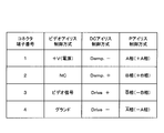
- FIG. 2 is a diagram showing the types of signals transmitted and received at each connector terminal in the video iris control system, the DC iris control system, and the P iris control system.
- FIG. 3 is a block diagram showing a functional configuration of iris control of the lens unit connector, the lens unit controller, and the iris actuator.
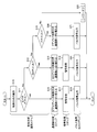
- FIG. 4 is a flowchart showing the flow of processing from signal reception to signal output in the lens unit controller.
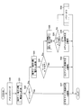
- FIG. 5 is a flowchart showing an example of the control method identification step.
- FIG. 1 is a block diagram showing an outline of a video camera connected to a management station via a network.
- the video camera 10 capable of shooting a still image and a moving image includes a replaceable lens unit 12 (video camera lens diaphragm device) and a video camera body 14 including an image sensor 28.
- the lens unit 12 and the video camera body 14 are electrically connected via the lens unit connector 26 of the lens unit 12 and the camera body connector 34 of the video camera body 14.
- the lens unit 12 can be interchangeably mounted on a video camera main body 14 that outputs a pulse signal for aperture control and a video camera main body 14 that outputs a signal for aperture control different from the pulse signal.
- the lens unit 12 includes an optical system including a lens 16, an iris (aperture) 18 and a filter (not shown), and an optical system operation unit 20 that controls the optical system.
- the optical system operation unit 20 includes a lens unit controller 24 connected to a lens unit connector 26.
- the lens unit controller 24 includes an iris actuator (pulse signal drive actuator) 22 that drives the iris 18, a lens 16, and the like.
- An actuator (not shown) for driving another optical system is connected.
- the iris 18 is a diaphragm mechanism that adjusts the diaphragm amount of the lens 16, and is constituted by a plurality of diaphragm blades. These diaphragm blades are driven by the iris actuator 22, and are moved from “a position where light is not blocked (open position)” to a position as closed as possible so as to block light (for example, a fully closed position) (closed).
- the "aperture" can be adjusted.
- the lens unit controller 24 controls the optical system via an actuator based on a control signal sent from the video camera main body 14 via the lens unit connector 26. For example, focus control or zoom control by moving the lens, iris actuator The iris amount control of the iris 18 through the control 22 is performed.
- the iris actuator 22 of this embodiment includes a pulse signal drive motor that drives the iris 18 (a diaphragm mechanism) in accordance with an input pulse signal.
- a pulse signal drive motor for example, a stepping motor can be suitably used.
- P iris control system first control system
- the stepping motor operates in synchronization with the pulse power and can perform accurate positioning control.
- the stepping motor of this example has a first phase (+ A phase, -A phase) and a second phase (+ B phase, -B phase), and the coil ports (+ A phase, -A phase, By changing the signal input pattern to (+ B phase, -B phase), the motor can be rotated to a desired angle.
- the lens unit connector 26 is connected to the video camera main body 14 (camera main body connector 34) and has a plurality of terminals (first terminal to fourth terminal) capable of communicating with the video camera main body 14.
- the imaging device 28 of the video camera main body 14 has a color filter such as RGB and an image sensor (CMOS, CCD, etc.), and an object irradiated through the optical system (lens 16, iris 18, etc.) of the lens unit 12.
- CMOS complementary metal-oxide-semiconductor
- the light of the image is converted into an electrical signal, and the image signal is sent to the camera body controller 30.
- the camera body controller 30 controls the video camera body 14 in an integrated manner, for example, performs image processing on an image signal from the image sensor 28 or creates a control signal for controlling the lens unit 12 to control the camera body connector 34.
- the lens unit 12 (lens unit controller 24), or to transmit image data before and after image processing to external devices (such as the management station 70) connected via the input / output interface 36.
- the camera body controller 30 can perform arbitrary image processing as necessary, and performs sensor correction processing, pixel interpolation processing, color correction processing, sharpness processing, tone correction processing, exposure correction processing, MPEG compression processing, and the like. be able to.
- a camera body memory 32 is connected to the camera body controller 30, and the camera body controller 30 saves and reads data in the camera body memory 32.
- the camera body memory 32 not only can store various types of data (data, programs, processing parameters, etc.) such as captured image data and image processed image data, but also for arithmetic processing of the camera body controller 30. It can also be used as a data development area.
- the camera body memory 32 may be configured as a built-in memory of the video camera body 14, a removable memory, or localized in a network attached storage unit, a personal computer, a server, or the like. May be.
- the image data processed by the camera body controller 30 is sent to the management station 70 via the network 60 connected to the input / output interface 36.
- the connection mode of the input / output interface 36 and the management station interface 72 of the video camera body 14 to the network 60 may be a wired connection or a wireless connection.
- the management station 70 is connected to the video camera 10 via the input / output interface 36, the network 60, and the management station interface 72 of the video camera body 14, and receives data such as image data sent from the video camera body 14. .
- a management station controller 74 connected to the management station interface 72 controls the management station 70 in an integrated manner. For example, the management station controller 74 controls the reception of image data from the video camera 10 and the transmission of a drive control signal for the video camera 10 and performs image processing on the received image data.
- the management station 70 has a display 76, and the processing contents in the management station controller 74 are displayed on the display 76 as necessary.
- the user inputs data and instructions to the management station controller 74 by operating an input unit (not shown) such as a keyboard while confirming the display on the display 76, and controls the video camera 10 connected to the management station 70. It is also possible to control.
- the user can also remotely control the video camera 10 via the management station 70. That is, the user displays an image captured by the video camera 10 on the display 76 of the management station 70, and while viewing the display 76, the video camera 10 adjustment instruction (for example, exposure control, pan / tilt operation, still image shooting instruction, The zoom control or the like can be remotely operated by operating an input unit such as a keyboard.
- Such remote operation is performed by the management station controller 74, the camera body controller 30, and the lens unit controller so that the video camera 10 is appropriately operated and controlled based on an instruction from the user input to the management station 70 (such as a keyboard).
- This is realized by 24 working together.
- Each of these controllers includes circuits necessary for control processing, and includes, for example, an arithmetic processing circuit (such as a CPU) and a memory.
- the video camera 10 may be provided with one management station 70 via the network 60, or may be provided with a plurality of management stations 70.
- the lens unit 12 and the video camera body 14 are appropriately connected when activated in order to establish an appropriate communication state between the camera body controller 30 and the lens unit controller 24. Whether or not the video camera body 14 has been detected is detected. In the present embodiment, the “control system of the iris 18” is detected by the lens unit controller 24.
- a video iris control method (second control method), a DC iris control method (third control method), and a P iris control method (first control method) are used as control methods for video cameras. Since the lens unit connector 26 and the camera body connector 34 have the same shape between these control methods, the lens unit 12 and the video camera body 14 having different control methods may be connected.
- FIG. 2 is a diagram illustrating signals transmitted and received at each terminal of the lens unit connector 26 in the video iris control method, the DC iris control method, and the P iris control method.
- the lens unit connector 26 and the camera body connector 34 have four terminals (first terminal, second terminal, third terminal, and fourth terminal).
- signals input to the first phase (+ A phase, -A phase) of the stepping motor can be communicated via the first terminal and the fourth terminal.
- Signals input to the second phase (+ B phase, ⁇ B phase) can communicate via the second terminal and the third terminal.
- the signal includes a video signal
- the first terminal can be used as a power supply terminal (+ V)
- the second terminal is an unconnected terminal (NC)
- the third terminal is The video signal (video signal) can be communicated
- the fourth terminal can be used as a ground terminal (GND).
- a signal (communication signal) includes a signal for controlling an actuator (analog signal driving actuator) that can be driven by an analog signal, and a braking signal (Damp. ⁇ ) is supplied via a first terminal and a second terminal. , Damp. +) And drive signals (Drive +, Drive ⁇ ) can be communicated via the third terminal and the fourth terminal.
- the lens unit 12 is not only for the video camera main body 14 that outputs the aperture control pulse signal (stepping motor drive signal), but also for the video camera main body that outputs an aperture control signal different from the pulse signal. Can be mounted interchangeably.
- a P-iris control system video camera body 14 when a P-iris control system video camera body 14 is connected to a P-iris control system lens unit 12 using a stepping motor, the video camera body 14 appropriately controls the lens unit 12 for operation. be able to.
- the DC iris control method or video iris control method video camera body 14 is connected to the P iris control method lens unit 12
- signals having different control methods are input to the lens unit connector 26.
- the lens unit controller 24 cannot properly control the iris actuator 22 based on the received signal.
- the signal (communication signal) transmitted and received between the video camera body 14 and the lens unit 12 through the camera body connector 34 and the lens unit connector 26 is. Is done.
- the iris actuator 22 is driven by the received signal in the P iris control system.
- the signal sent from the video camera main body 14 is identified as the video iris control method or the DC iris control method
- the received signal is signaled as a signal suitable for driving the iris actuator 22 (stepping motor). Then, the iris actuator 22 is driven by the signal after this signal processing.
- FIG. 3 is a block diagram showing the functional configuration of the iris control of the lens unit connector 26, the lens unit controller 24 and the iris actuator 22 of the lens unit 12. As shown in FIG.
- the signal received via the lens unit connector 26 is output to the iris actuator 22 via the lens unit controller 24 in the form of a stepping motor drive signal (pulse signal).
- the lens unit controller 24 functions as a control unit that controls the iris actuator 22 by a pulse signal based on a signal received via the lens unit connector 26, and includes a signal type identification CPU (identification unit) 40, a switching circuit 42, and a switching circuit 42. Unit 43, switch 44 (switching unit), and various signal processing units.
- the signal type identification CPU (identification unit) 40 identifies the signal type (control method) based on the voltage of the signal transmitted / received via the lens unit connector 26.
- the switching circuit 42, the switching device 43, and the switching device 44 switch the communication path according to the identified signal type (control method).
- the signal processing unit performs various types of signal processing for acquiring a pulse signal based on the identified signal type (control method).
- the signal type identifying CPU 40 identifies the signal control method based on the voltage of the signal transmitted and received by the first terminal 26-1 to the fourth terminal 26-4 of the lens unit connector 26.
- the signal type identifying CPU 40 in this example identifies which control method is the P iris control method, the video iris control method, or the DC iris control method. Then, the signal type identification CPU 40 transmits a signal type determination signal indicating the identification result to the switching circuit 42.
- the switching circuit 42 that has received the signal type determination signal transmits a communication path switching signal according to the control method of the signal identified by the signal type identification CPU 40 to the switching unit 43 and the switching unit 44, and switches the communication path.
- a communication path for a DC iris control system signal, a communication path for a video iris control system, and a communication path for a P iris control system are provided.
- the switching circuit 42 controls the switching unit 43 connected to the lens unit connector 26 and the switching unit 44 connected to the iris actuator 22, and the control method in which the signal received via the lens unit connector 26 is identified.
- the communication path corresponding to the is transmitted.
- the control method of the signal transmitted / received via the lens unit connector 26 is identified as a control method (P iris control method) based on a pulse signal capable of directly driving the iris actuator 22, the signal processing unit The switching circuit 42 switches the communication path by controlling the switch 43 and the switch 44 so that the signal from the video camera body 14 is output to the iris actuator 22 (see “P iris control” in FIG. 3).
- P iris control a control method
- the signal processing unit The switching circuit 42 switches the communication path by controlling the switch 43 and the switch 44 so that the signal from the video camera body 14 is output to the iris actuator 22 (see “P iris control” in FIG. 3).
- Methodhod Communication Channel On the other hand, when it is identified that the control method of the signal transmitted / received via the lens unit connector 26 is based on a control method (DC iris control method or video iris control method) that cannot directly drive the iris actuator 22.
- the switching circuit 42 includes a switch 43 and a switch 44 so that a pulse signal capable of driving the iris actuator 22 is generated by the signal processing unit based on the signal (signal control method) and output to the iris actuator 22.
- a pulse signal capable of driving the iris actuator 22 is generated by the signal processing unit based on the signal (signal control method) and output to the iris actuator 22.
- the signal processing unit performs signal processing for acquiring the “stepping motor drive pulse signal” according to the identified control method.
- the signal of the DC iris control method and the signal of the video iris control method are signal-processed into the drive pulse signal for the stepping motor, the signal unique to each of the DC iris control method communication channel and the video iris control method communication channel.
- a processing unit is provided.
- a DC iris signal conversion circuit 47 for example, in the DC iris control system communication path, a DC iris signal conversion circuit 47, an analog / digital converter 48 (ADC 48a and DAC 48b), a DC signal adjustment CPU 49 and a stepping motor driver (STM driver) 50 are switched as signal processing units.
- the video iris control system communication path includes a power source 51, a detection / smoothing circuit 52, a level comparison circuit 53, an AD conversion circuit 54, a video signal adjustment CPU 55, and a stepping motor driver 56 as a signal processor.
- the switch 44 is sequentially provided.
- the received signal is identified as the DC iris control method by the signal type identifying CPU 40 and switched.
- the communication path is switched to the DC iris control type communication path by the circuit 42, the switch 43 and the switch 44.
- the DC iris signal conversion circuit 47 performs signal conversion processing of transmission / reception signals (drive signal and braking signal), and the analog / digital converter 48 converts the drive signal from an analog signal to a digital signal by the ADC 48a.
- the brake signal is converted from a digital signal to an analog signal by the DAC 48b.
- the drive signal in the digital signal format is converted into a pulse signal for the iris actuator (stepping motor) 22 in order to appropriately control the iris 18 (aperture control). That is, the DC signal adjustment CPU 49 functions as a signal generation unit that generates a pulse signal based on a signal (transmission / reception signal).
- the stepping motor driver (STM driver) 50 adjusts to specific signals (first phase signal and second phase signal) that can drive the iris actuator 22, and the adjusted signal is passed through the switch 44. And output to the iris actuator 22.
- a driving voltage based on a luminance signal obtained from a video signal in the video camera main body 14 is input to the lens unit 12 side, and a braking signal (braking voltage) corresponding to the rotation speed of the motor is input to the video camera main body. 14 side.
- a braking signal braking voltage
- On the video camera body 14 side feedback control is performed to adjust the drive voltage in consideration of the input braking voltage.
- the video camera main body 14 side on the side of the video camera main body 14 (lens unit 12)) as if it is controlling the “DC iris control system iris 18 (lens unit 12)”. It is necessary to pretend to the camera body controller 30).
- the DC signal adjusting CPU 49 appropriately calculates a braking signal, and this braking signal is sent to the camera body controller 30 via the DAC 48b, the DC iris signal conversion circuit 47, the switch 43, the lens unit connector 26, and the camera body connector 34. Sent and used as a feedback signal for the servo circuit on the camera side.
- the signal type identification CPU 40 identifies that the received signal is the video iris control method.
- the communication path is switched to the video iris control type communication path by the switching circuit 42, the switching unit 43, and the switching unit 44.
- the power supply 51 is supplied with voltage signals from the first terminal 26-1 and the fourth terminal 26-4.
- the video signal (luminance signal) received by the third terminal 26-3 is detected and smoothed by the detection / smoothing circuit 52 and converted to a direct current, and the level comparison circuit 53 determines the voltage level of the converted video signal as a reference.
- This drive signal is converted from an analog signal into a digital signal by the AD conversion circuit 54, and the video signal adjustment CPU 55 converts the iris signal (from the digital signal format) into an iris actuator (to control the iris 18 appropriately). Converted into a pulse signal for a stepping motor 22. That is, the video signal adjusting CPU 55 functions as a signal generation unit that generates a pulse signal based on a signal (transmission / reception signal).
- the stepping motor driver 56 adjusts specific signals (first phase signal and second phase signal) that can drive the iris actuator 22, and the adjusted signal is passed through the switch 44 to the iris actuator 22. Is output.
- the lens unit controller 24 having the signal type identifying CPU 40 and the signal processing unit converts the pulse signal into the iris actuator 22 based on the signals communicated through the first terminal 26-1 to the fourth terminal 26-4. Can be output.
- FIG. 4 is a flowchart showing the flow of processing from signal reception to signal output in the lens unit controller 24.
- the aperture control method in the lens unit controller 24 of this example includes a step of identifying a control method of an iris control signal received by the lens unit connector 26, a step of switching a communication path according to the identified control method, and an identified control method And a step of outputting a pulse signal to the iris actuator 22.
- the signal type identification CPU 40 identifies the control method of signals transmitted and received via the lens unit connector 26 (S10 in FIG. 4).
- the signal control method is identified based on the voltage of the signal communicated through the first terminal 26-1 to the fourth terminal 26-4. Details of the method for identifying the signal control method will be described later (see FIG. 5).
- the switching circuit 42 controls the switch 43 and the switch 44 to open the video iris control method communication path, and to communicate with other control methods. Is closed (S14).
- the switching circuit 42 controls the switch 43 and the switch 44 to perform DC iris control method communication.
- the path is opened and the communication path of the other control method is closed (S15).
- the switching circuit 42 controls the switch 43 and the switch 44 to perform the P iris control method communication.
- the path is opened and the communication path of the other control method is closed (S16).
- the signal type identification CPU 40 indicates an error indicating that it cannot be handled.
- a signal is transmitted to the camera body controller 30 via the lens unit connector 26 and the camera body connector 34, and a power off signal is transmitted to the power off circuit 46 to power off the lens unit 12 (S22).
- the camera body controller 30 that has received the error signal transmits an error signal to the management station 70 to notify the user that the combination of the lens unit 12 and the video camera body 14 is inappropriate.
- the signal processing unit When switched to the video iris control system communication path (S14) or when switched to the DC iris control system communication path (S15), the signal processing unit (see FIG. 3) provided in each communication path. By the signal processing, a pulse signal for driving the iris actuator 22 is generated (S17, S18).
- the video iris control system signal passes through the power source 51, the detection / smoothing circuit 52, the level comparison circuit 53, the AD conversion circuit 54, the video signal adjustment CPU 55, and the stepping motor driver 56, and then passes through the iris actuator 22 (stepping motor).
- Signal processing is performed on a pulse signal for driving.
- the signal of the DC iris control system drives the iris actuator 22 (stepping motor) through the DC iris signal conversion circuit 47, the analog / digital converter 48 (ADC 48a and DAC 48b), the DC signal adjustment CPU 49 and the stepping motor driver 50.
- the signal is processed into a pulse signal.
- the pulse signal created from the video iris control system signal or the DC iris control system signal is output to the iris actuator 22 via the switch 44 (S19, S20).
- the received signal of the lens unit connector 26 is an appropriate pulse signal as the control signal of the iris actuator 22. And is output to the iris actuator 22 without passing through the signal processing (S17, S18) (S21).
- a pulse signal suitable for driving the stepping motor is input to the iris actuator 22, and the iris actuator 22 controls the iris 18 according to the input pulse signal, and a desired value is obtained. Aperture amount is achieved.
- FIG. 5 is a flowchart showing an example of the control method identification step.
- the identification step described below may be automatically executed without being instructed by the user via the management station 70 when the lens unit 12 and the video camera main body 14 are activated. Although preferable, it may be executed in response to an instruction from the user via the management station 70.
- control method identification step When identifying the control method of a signal communicated through the lens unit connector 26 (control method identification step), first, the iris amount is adjusted by the iris 18 (see FIG. 1), and the iris of the video camera lens is once fully closed. (S30 in FIG. 5). That is, the CPU 40 for signal type identification transmits a pulse signal (iris full close instruction signal) for fully closing the iris 18 to the iris actuator 22 before entering the specific identification process of the signal control method. 18 is fully closed.
- a pulse signal iris full close instruction signal
- the voltage of the iris drive signal increases (for example, indicates a maximum value) under the auto iris control method (particularly, the DC iris control method).
- the following determination for identifying the signal control method based on the voltage of the signal received by each terminal of the lens unit connector 26 can be performed with high accuracy.
- the signal type identifying CPU 40 detects a signal (communication signal) communicated via the first terminal 26-1 to the fourth terminal 26-4 after the diaphragm of the video camera lens is fully closed, and the first terminal 26 -1 and detecting measured signal voltage V 14 between the fourth terminal 26-4 (S31).
- the signal type identifying CPU 40 determines that the signal voltage V 14 (absolute value) between the first terminal 26-1 and the fourth terminal 26-4 of the lens unit connector 26 is based on the power supply voltage of the video iris control system. It is determined whether or not the voltage is higher than the predetermined voltage (S32). If the voltage is higher than the predetermined voltage (Yes in S32), the control method of the signal from the video camera body 14 is identified as the video iris control method (S37). .
- the “predetermined voltage” used in the determination (S32) is lower than the power supply voltage of the video iris control method, and the first terminal 26-1 and the fourth terminal of the DC iris control method and the P iris control method are used. What is necessary is just to be larger than the voltage between the terminals 26-4.
- the power supply voltage of the video iris control method is about “9 to 12 volts”
- the first terminal 26-1 and the fourth terminal 26-4 of the DC iris control method and the P iris control method are In view of the fact that the voltage between is about "4 to 7 volts", the "predetermined voltage” is set to 8 volts.
- the signal type identification CPU40 includes a third terminal 26-3
- the signal voltage V 34 between the fourth terminal 26-4 is detected and measured (S33).
- the signal type identification CPU 40 In the signal type identification CPU 40, the signal voltage V 34 (absolute value) between the third terminal 26-3 and the fourth terminal 26-4 is greater than a predetermined voltage determined based on the drive signal voltage of the DC iris control method. And whether the signals received by the third terminal 26-3 and the fourth terminal 26-4 are DC signals (DC signals) is determined (S34). When these conditions are satisfied (Yes in S34), the signal type identifying CPU 40 identifies the control method of the signal from the video camera body 14 as the DC iris control method (S38).
- the signal of the DC iris control system is a direct current signal
- the signal of the P iris control system is a pulse signal.
- the determination as to whether or not the signal voltage V 34 is greater than “a predetermined voltage determined based on the drive signal voltage of the DC iris control method” is mainly for the purpose of eliminating the influence of the noise signal. As long as it is smaller than the drive signal voltage of the DC iris control method and larger than the noise signal voltage to be excluded. In the example shown in FIG. 5, the “predetermined voltage” is set to 3 volts in view of the drive signal voltage of the DC iris control method being about “4 volts”.
- whether or not the signals received by the third terminal 26-3 and the fourth terminal 26-4 are direct current signals (DC signals)” can be determined by an arbitrary method, for example, the third terminal 26 -3 and the fourth terminal 26-4 can determine that the signal is a DC signal when the signal received by the fourth terminal 26-4 is equal to or higher than a certain voltage value (eg, about 3 seconds). This is based on the fact that it is possible to determine whether or not the signal is a direct current signal by confirming that the pulse signal does not show an instantaneous increase or decrease voltage behavior.
- a certain voltage value eg, about 3 seconds
- the signal type identification CPU40 includes a first terminal 26-1 and the signal voltage V 14 and the second terminal 26-2 between the fourth terminal 26-4 third terminal 26 detecting measured signal voltage V 23 between the -3 (S35).
- Signal type identification CPU40 a signal voltage V 23 between the signal voltage V 14 and the second terminal 26-2 between the first terminal 26-1 and the fourth terminal 26-4 and the third terminal 26-3 (Absolute value) of each of the first terminal 26-1, the second terminal 26-2, the second terminal 26-2, the second terminal 26-2, the second terminal 26-2, and the second terminal 26-2. It is determined whether the signal communicated through the third terminal 26-3 and the fourth terminal 26-4 is a pulse signal (S36). When these conditions are satisfied (Yes in S36), the signal type identifying CPU 40 identifies that the control method of the signal from the video camera body 14 is the P iris control method (S39).
- the drive signal (stepping motor drive signal) of the P iris control system is a pulse signal, and the voltage of such a pulse signal is about “4 volts”.
- a predetermined voltage determined based on the voltage of the pulse signal for driving the iris actuator 22 (stepping motor) is mainly determined by a noise signal.
- the predetermined voltage should be smaller than the drive signal voltage of the stepping motor of the P iris control method and larger than the noise signal voltage to be excluded. In the example shown in FIG. 5, the “predetermined voltage” is set to 3 volts in view of the drive signal voltage of the P-iris control method being about “4 volts”.
- a signal communicated through each terminal of the lens unit connector 26 is a video iris control method, a DC iris control method, and a P signal. It is determined that none of the iris control methods.
- the signal type identifying CPU 40 transmits an error signal to the camera body controller 30, and transmits a power-off signal to the power-off circuit 46 to power off the lens unit 12 (S40: see S22 in FIG. 4). .
- the lens unit 12 (lens unit controller 24) of the present embodiment, even if the iris control signal from the video camera body 14 is the DC iris control method or the video iris control method, the P iris control is performed.
- the iris 18 can be controlled to a desired aperture amount by driving and controlling the lens unit 12 (iris actuator 22) of the system.
- processing circuit described above can be appropriately realized by various hardware, software (program), or a combination of both, and a plurality of processing circuits can also be realized by a single configuration circuit.
- the signal type identifying CPU 40, the DC signal adjusting CPU 49, and the video signal adjusting CPU 55 are illustrated as separate functional configurations, but each CPU shown in FIG. 3 is realized by a single CPU. It is also possible to do. The same applies to the stepping motor driver 50 and the stepping motor driver 56 of FIG. 3, and these drivers can be realized by a single driver.
- the iris actuator 22 can employ another type of pulse signal drive motor (ultrasonic motor or the like).
Landscapes
- Physics & Mathematics (AREA)
- General Physics & Mathematics (AREA)
- Engineering & Computer Science (AREA)
- Optics & Photonics (AREA)
- Power Engineering (AREA)
- Multimedia (AREA)
- Signal Processing (AREA)
- Automation & Control Theory (AREA)
- Structure And Mechanism Of Cameras (AREA)
- Studio Devices (AREA)
- Diaphragms For Cameras (AREA)
Abstract
Description
Claims (8)
- 絞り制御用のパルス信号を出力するビデオカメラ本体及びパルス信号とは異なる絞り制御用の信号を出力するビデオカメラ本体に対して交換可能に装着されるビデオカメラ用レンズの絞り装置であって、
レンズの絞り量を調整する絞り機構と、
入力されるパルス信号に応じて前記絞り機構を駆動するパルス信号駆動アクチュエータと、
ビデオカメラ本体に接続され、前記ビデオカメラ本体との間で通信可能な複数の端子を有するコネクタと、
前記複数の端子を介して通信される信号の電圧に基づいて当該信号の制御方式を識別する識別部と、
識別された前記制御方式に応じて前記信号の通信路を切り替える切替部を有し、前記信号に基づくパルス信号により前記パルス信号駆動アクチュエータを制御する制御部と、を備え、
前記切替部は、前記信号の制御方式が前記パルス信号駆動アクチュエータを直接駆動可能ではない制御方式に基づくものであると識別される場合には、前記信号に基づいてパルス信号を生成する信号生成部により、前記パルス信号駆動アクチュエータを駆動可能なパルス信号が生成されて前記パルス信号駆動アクチュエータに出力されるように、前記通信路を切り替え、
前記切替部は、前記信号の制御方式が前記パルス信号駆動アクチュエータを直接駆動可能なパルス信号に基づく第1の制御方式であると識別される場合には、前記信号が前記パルス信号駆動アクチュエータに出力されるように、前記通信路を切り替えるビデオカメラ用レンズの絞り装置。 - 前記パルス信号駆動アクチュエータを直接駆動可能ではない制御方式は、前記信号がビデオ信号を含む第2の制御方式、および、前記信号がアナログ信号駆動アクチュエータを制御するための信号を含む第3の制御方式、を含む請求項1に記載のビデオカメラ用レンズの絞り装置。
- 前記複数の端子は、第1端子、第2端子、第3端子及び第4端子を含み、
前記第1の制御方式では、前記第1端子及び前記第4端子を介して前記パルス信号駆動アクチュエータの第1相に入力される信号を通信可能であり、前記第2端子及び前記第3端子を介して前記パルス信号駆動アクチュエータの第2相に入力される信号を通信可能であり、
前記第2の制御方式では、前記第1端子は電源端子として使用可能であり、前記第3端子を介して映像信号を通信可能であり、前記第4端子はグランド端子として使用可能であり、
前記第3の制御方式では、前記第1端子及び前記第2端子を介して制動信号を通信可能であり、前記第3端子及び前記第4端子を介して駆動信号を通信可能である請求項2に記載のビデオカメラ用レンズの絞り装置。 - 前記識別部は、前記第1端子と前記第4端子との間の電圧及び前記第2端子と前記第3端子との間の電圧の各々が、前記パルス信号駆動アクチュエータを駆動するためのパルス信号の電圧を基準に定められる電圧よりも大きく、且つ、前記第1端子、前記第2端子、前記第3端子及び前記第4端子を介して通信される信号がパルス信号である場合には、前記信号の制御方式が前記第1の制御方式であると識別する請求項3に記載のビデオカメラ用レンズの絞り装置。
- 前記識別部は、前記第1端子と前記第4端子との間の電圧が、前記第2の制御方式の電源電圧を基準に定められる電圧よりも大きい場合には、前記信号の制御方式が前記第2の制御方式であると識別する請求項3または4に記載のビデオカメラ用レンズの絞り装置。
- 前記識別部は、前記第3端子と前記第4端子との間の電圧が、前記第3の制御方式の駆動信号電圧を基準に定められる電圧よりも大きく、且つ、前記第3端子及び前記第4端子を介して通信される信号が直流信号である場合には、前記信号の制御方式が前記第3の制御方式であると識別する請求項3から5のいずれか1項に記載のビデオカメラ用レンズの絞り装置。
- 絞り制御用のパルス信号を出力するビデオカメラ本体及びパルス信号とは異なる絞り制御用の信号を出力するビデオカメラ本体に対して交換可能に装着されるビデオカメラ用レンズの絞り装置であって、レンズの絞り量を調整する絞り機構と、入力されるパルス信号に応じて前記絞り機構を駆動するパルス信号駆動アクチュエータと、ビデオカメラ本体に接続され、前記ビデオカメラ本体との間で通信可能な複数の端子を有するコネクタと、前記複数の端子を介して通信される信号の電圧に基づいて当該信号の制御方式を識別する識別部と、識別された前記制御方式に応じて前記信号の通信路を切り替える切替部を有し、前記信号に基づくパルス信号により前記パルス信号駆動アクチュエータを制御する制御部と、を備えるビデオカメラ用レンズの絞り装置の制御方法において、
前記複数の端子を介して通信される信号の電圧に基づいて、当該信号の制御方式を識別するステップと、
識別された前記信号の制御方式に基づいて前記通信路を切り替えるステップと、を含み、
前記切替部は、前記信号の制御方式が前記パルス信号駆動アクチュエータを直接駆動可能ではない制御方式に基づくものであると識別される場合には、前記信号に基づいてパルス信号を生成する信号生成部により、前記パルス信号駆動アクチュエータを駆動可能なパルス信号が生成されて前記パルス信号駆動アクチュエータに出力されるように、前記通信路を切り替え、
前記切替部は、前記信号の制御方式が前記パルス信号駆動アクチュエータを直接駆動可能なパルス信号に基づく第1の制御方式であると識別される場合には、前記信号が前記パルス信号駆動アクチュエータに出力されるように、前記通信路を切り替えるビデオカメラ用レンズの絞り装置の制御方法。 - 前記複数の端子は、第1端子、第2端子、第3端子及び第4端子を含み、
前記第1の制御方式では、前記第1端子及び前記第4端子を介して前記パルス信号駆動アクチュエータの第1相に入力される信号を通信可能であり、前記第2端子及び前記第3端子を介して前記パルス信号駆動アクチュエータの第2相に入力される信号を通信可能であり、
第2の制御方式では、前記第1端子は電源端子として使用可能であり、前記第3端子を介して映像信号を通信可能であり、前記第4端子はグランド端子として使用可能であり、
第3の制御方式では、前記第1端子及び前記第2端子を介して制動信号を通信可能であり、前記第3端子及び前記第4端子を介して駆動信号を通信可能であり、
前記信号の制御方式を識別する前記ステップは、前記絞り機構によって前記絞り量を調整して絞りを一旦全閉にするステップと、絞りの全閉後に前記第1端子、前記第2端子、前記第3端子及び前記第4端子を介して通信される前記信号を検出するステップとを有する請求項7に記載のビデオカメラ用レンズの絞り装置の制御方法。
Priority Applications (3)
| Application Number | Priority Date | Filing Date | Title |
|---|---|---|---|
| JP2015507936A JP5887464B2 (ja) | 2013-03-29 | 2013-10-22 | ビデオカメラ用レンズの絞り装置及びその制御方法 |
| CN201380074912.7A CN105143973B (zh) | 2013-03-29 | 2013-10-22 | 摄像机用镜头的光圈装置及其控制方法 |
| US14/869,031 US9921455B2 (en) | 2013-03-29 | 2015-09-29 | Diaphragm device for video camera lens and method for controlling diaphragm device |
Applications Claiming Priority (2)
| Application Number | Priority Date | Filing Date | Title |
|---|---|---|---|
| JP2013-073946 | 2013-03-29 | ||
| JP2013073946 | 2013-03-29 |
Related Child Applications (1)
| Application Number | Title | Priority Date | Filing Date |
|---|---|---|---|
| US14/869,031 Continuation US9921455B2 (en) | 2013-03-29 | 2015-09-29 | Diaphragm device for video camera lens and method for controlling diaphragm device |
Publications (1)
| Publication Number | Publication Date |
|---|---|
| WO2014155797A1 true WO2014155797A1 (ja) | 2014-10-02 |
Family
ID=51622835
Family Applications (1)
| Application Number | Title | Priority Date | Filing Date |
|---|---|---|---|
| PCT/JP2013/078524 Ceased WO2014155797A1 (ja) | 2013-03-29 | 2013-10-22 | ビデオカメラ用レンズの絞り装置及びその制御方法 |
Country Status (4)
| Country | Link |
|---|---|
| US (1) | US9921455B2 (ja) |
| JP (1) | JP5887464B2 (ja) |
| CN (1) | CN105143973B (ja) |
| WO (1) | WO2014155797A1 (ja) |
Cited By (1)
| Publication number | Priority date | Publication date | Assignee | Title |
|---|---|---|---|---|
| WO2018179319A1 (ja) * | 2017-03-31 | 2018-10-04 | Cbc株式会社 | カメラ装置およびレンズ装置 |
Families Citing this family (7)
| Publication number | Priority date | Publication date | Assignee | Title |
|---|---|---|---|---|
| CN105143973B (zh) * | 2013-03-29 | 2018-02-27 | 富士胶片株式会社 | 摄像机用镜头的光圈装置及其控制方法 |
| US20190079370A1 (en) * | 2017-09-11 | 2019-03-14 | Tactacam LLC | Autofocus and autozoom recording system |
| US10321068B2 (en) * | 2017-09-13 | 2019-06-11 | The United States Of America As Represented By The Secretary Of The Navy | Image-based auto-iris |
| CN108536057A (zh) * | 2018-03-26 | 2018-09-14 | 福建福光股份有限公司 | P-iris的寿命检测控制电路 |
| CN109061980B (zh) * | 2018-09-20 | 2024-06-14 | 成都臻识科技发展有限公司 | 一种摄像机及应用于摄像机的光圈类型检测电路 |
| CN111586396B (zh) * | 2019-02-19 | 2022-07-19 | 浙江宇视科技有限公司 | 一种摄像机、图像处理器、光圈镜头类型识别方法和装置 |
| JP7428818B2 (ja) * | 2020-09-24 | 2024-02-06 | Cbc株式会社 | レンズ装置、レンズ装置が組み込まれたシステム、レンズ装置が組み込まれた検査装置、並びに操作用プログラム |
Citations (3)
| Publication number | Priority date | Publication date | Assignee | Title |
|---|---|---|---|---|
| JP2003015185A (ja) * | 2001-06-27 | 2003-01-15 | Mitsubishi Electric Corp | カメラ用レンズ装置 |
| JP2005099530A (ja) * | 2003-09-25 | 2005-04-14 | Fujitsu General Ltd | レンズ種別切換回路 |
| JP2011077643A (ja) * | 2009-09-29 | 2011-04-14 | Canon Inc | 撮像装置及びその制御方法 |
Family Cites Families (9)
| Publication number | Priority date | Publication date | Assignee | Title |
|---|---|---|---|---|
| JPH0772781B2 (ja) * | 1983-08-02 | 1995-08-02 | 株式会社ニコン | カメラ |
| JPH07101926B2 (ja) | 1988-07-20 | 1995-11-01 | 三洋電機株式会社 | 撮像装置 |
| JP3849192B2 (ja) * | 1996-12-09 | 2006-11-22 | 株式会社ニコン | カメラシステム及びカメラボディ |
| JP3535450B2 (ja) | 2000-05-08 | 2004-06-07 | ワテック株式会社 | ビデオカメラにおけるビデオカメラと自動絞りレンズとの交換接続装置およびその検出回路 |
| EP2354843B1 (en) | 2010-02-09 | 2020-01-01 | Axis AB | Calibration of a Lense Device |
| CN105143973B (zh) * | 2013-03-29 | 2018-02-27 | 富士胶片株式会社 | 摄像机用镜头的光圈装置及其控制方法 |
| CN105432068B (zh) * | 2013-08-01 | 2018-08-24 | 富士胶片株式会社 | 摄像装置、摄像方法及图像处理装置 |
| WO2015015944A1 (ja) * | 2013-08-02 | 2015-02-05 | 富士フイルム株式会社 | 画像処理装置、撮像装置、画像処理方法及びプログラム |
| JP5873207B1 (ja) * | 2015-07-15 | 2016-03-01 | 株式会社日本ビデオシステム | システムカメラレンズアダプタ |
-
2013
- 2013-10-22 CN CN201380074912.7A patent/CN105143973B/zh active Active
- 2013-10-22 JP JP2015507936A patent/JP5887464B2/ja active Active
- 2013-10-22 WO PCT/JP2013/078524 patent/WO2014155797A1/ja not_active Ceased
-
2015
- 2015-09-29 US US14/869,031 patent/US9921455B2/en active Active
Patent Citations (3)
| Publication number | Priority date | Publication date | Assignee | Title |
|---|---|---|---|---|
| JP2003015185A (ja) * | 2001-06-27 | 2003-01-15 | Mitsubishi Electric Corp | カメラ用レンズ装置 |
| JP2005099530A (ja) * | 2003-09-25 | 2005-04-14 | Fujitsu General Ltd | レンズ種別切換回路 |
| JP2011077643A (ja) * | 2009-09-29 | 2011-04-14 | Canon Inc | 撮像装置及びその制御方法 |
Cited By (1)
| Publication number | Priority date | Publication date | Assignee | Title |
|---|---|---|---|---|
| WO2018179319A1 (ja) * | 2017-03-31 | 2018-10-04 | Cbc株式会社 | カメラ装置およびレンズ装置 |
Also Published As
| Publication number | Publication date |
|---|---|
| US9921455B2 (en) | 2018-03-20 |
| JP5887464B2 (ja) | 2016-03-16 |
| CN105143973A (zh) | 2015-12-09 |
| US20160018717A1 (en) | 2016-01-21 |
| JPWO2014155797A1 (ja) | 2017-02-16 |
| CN105143973B (zh) | 2018-02-27 |
Similar Documents
| Publication | Publication Date | Title |
|---|---|---|
| JP5887464B2 (ja) | ビデオカメラ用レンズの絞り装置及びその制御方法 | |
| CN107343138B (zh) | 镜头单元、控制方法、存储介质及摄像设备 | |
| US11172136B2 (en) | Image capturing apparatus, control apparatus, storage medium, and control method | |
| US20140347541A1 (en) | Imaging apparatus and method of displaying captured image | |
| JP2013257411A5 (ja) | 外部ストロボ装置および撮像装置 | |
| US20080055458A1 (en) | Lens apparatus | |
| US10001697B2 (en) | Image capture apparatus, accessory, method for controlling them, and image capture system | |
| TW201406147A (zh) | 影像處理設備與其控制方法及影像擷取設備 | |
| JP2003324670A (ja) | 投写型映像表示装置 | |
| JP5618560B2 (ja) | 撮像装置、駆動制御装置、制御方法、及びプログラム | |
| JP5704828B2 (ja) | 撮像装置及びその制御方法 | |
| JP2017126914A (ja) | 画像処理システム | |
| JP4868600B2 (ja) | 撮像装置の制御装置 | |
| JP2021150718A (ja) | 情報処理装置、情報処理方法及びプログラム | |
| JP2025073514A (ja) | アクセサリ、アクセサリの制御方法、およびプログラム | |
| JP5047769B2 (ja) | Cctvカメラシステム | |
| JP2005198097A (ja) | 撮像装置及び発光装置及び当該撮像装置における撮像方法と撮像システム、及びそのプログラム | |
| JP7028349B2 (ja) | 表示制御装置及び表示制御システム | |
| JP2013128158A (ja) | 撮像装置 | |
| JP4834009B2 (ja) | テレビカメラシステム | |
| JP2019092132A (ja) | 表示制御装置及び表示制御システム | |
| JP2009198956A (ja) | 撮像装置及びプログラム | |
| JPH0310580A (ja) | レンズユニット及びカメラシステム | |
| JP4637080B2 (ja) | 映像表示装置 | |
| JP4654098B2 (ja) | テレビジョンカメラの調整方法 |
Legal Events
| Date | Code | Title | Description |
|---|---|---|---|
| WWE | Wipo information: entry into national phase |
Ref document number: 201380074912.7 Country of ref document: CN |
|
| 121 | Ep: the epo has been informed by wipo that ep was designated in this application |
Ref document number: 13880209 Country of ref document: EP Kind code of ref document: A1 |
|
| ENP | Entry into the national phase |
Ref document number: 2015507936 Country of ref document: JP Kind code of ref document: A |
|
| NENP | Non-entry into the national phase |
Ref country code: DE |
|
| 122 | Ep: pct application non-entry in european phase |
Ref document number: 13880209 Country of ref document: EP Kind code of ref document: A1 |