WO2014148546A1 - 燃焼バーナ、バーナ装置、及び原料粉体加熱方法 - Google Patents
燃焼バーナ、バーナ装置、及び原料粉体加熱方法 Download PDFInfo
- Publication number
- WO2014148546A1 WO2014148546A1 PCT/JP2014/057514 JP2014057514W WO2014148546A1 WO 2014148546 A1 WO2014148546 A1 WO 2014148546A1 JP 2014057514 W JP2014057514 W JP 2014057514W WO 2014148546 A1 WO2014148546 A1 WO 2014148546A1
- Authority
- WO
- WIPO (PCT)
- Prior art keywords
- raw material
- material powder
- combustion
- burner
- supply path
- Prior art date
- Legal status (The legal status is an assumption and is not a legal conclusion. Google has not performed a legal analysis and makes no representation as to the accuracy of the status listed.)
- Ceased
Links
Images





Classifications
-
- F—MECHANICAL ENGINEERING; LIGHTING; HEATING; WEAPONS; BLASTING
- F23—COMBUSTION APPARATUS; COMBUSTION PROCESSES
- F23D—BURNERS
- F23D1/00—Burners for combustion of pulverulent fuel
-
- F—MECHANICAL ENGINEERING; LIGHTING; HEATING; WEAPONS; BLASTING
- F23—COMBUSTION APPARATUS; COMBUSTION PROCESSES
- F23D—BURNERS
- F23D14/00—Burners for combustion of a gas, e.g. of a gas stored under pressure as a liquid
- F23D14/20—Non-premix gas burners, i.e. in which gaseous fuel is mixed with combustion air on arrival at the combustion zone
- F23D14/22—Non-premix gas burners, i.e. in which gaseous fuel is mixed with combustion air on arrival at the combustion zone with separate air and gas feed ducts, e.g. with ducts running parallel or crossing each other
-
- F—MECHANICAL ENGINEERING; LIGHTING; HEATING; WEAPONS; BLASTING
- F23—COMBUSTION APPARATUS; COMBUSTION PROCESSES
- F23D—BURNERS
- F23D14/00—Burners for combustion of a gas, e.g. of a gas stored under pressure as a liquid
- F23D14/20—Non-premix gas burners, i.e. in which gaseous fuel is mixed with combustion air on arrival at the combustion zone
-
- F—MECHANICAL ENGINEERING; LIGHTING; HEATING; WEAPONS; BLASTING
- F23—COMBUSTION APPARATUS; COMBUSTION PROCESSES
- F23D—BURNERS
- F23D14/00—Burners for combustion of a gas, e.g. of a gas stored under pressure as a liquid
- F23D14/46—Details
- F23D14/48—Nozzles
- F23D14/58—Nozzles characterised by the shape or arrangement of the outlet or outlets from the nozzle, e.g. of annular configuration
-
- F—MECHANICAL ENGINEERING; LIGHTING; HEATING; WEAPONS; BLASTING
- F23—COMBUSTION APPARATUS; COMBUSTION PROCESSES
- F23D—BURNERS
- F23D17/00—Burners for combustion simultaneously or alternately of gaseous or liquid or pulverulent fuel
Definitions
- the present invention relates to a combustion burner for heating powder (raw material powder), a burner device, and a raw material powder heating method.
- Combustion burners are used for melting metals such as iron, manufacturing glass, and incinerating garbage.
- a method of heating an object such as metal, glass, and garbage using a combustion burner there are a method in which a flame is directly applied to the object and a method in which the object is heated indirectly by the radiant heat of the flame. is there.
- the method of heating by directly applying the flame to the object has an advantage that the energy use efficiency is higher than the method of heating the object indirectly by the radiant heat of the flame.
- Patent Document 1 discloses that a cold iron source is dissolved by using a combustion burner that directly heats a flame against an object and heats it.
- the object to be heated is a powder (raw material powder)
- the surface area per volume of the object is large, and therefore the flame and / or a high temperature region near the flame (hereinafter referred to as “flame region”) is passed.
- flame region a high temperature region near the flame
- Patent Documents 2 to 4 a combustion burner is provided in which a powder outlet from which powder is ejected is installed in the vicinity of a combustion burner or a combustion burner, and at the same time as the powder is ejected, the powder is directly charged into the flame region and heated. And a combustion method are disclosed.
- a powder outlet is disposed at the center of the combustion burner or in the vicinity thereof (hereinafter referred to as “the center portion of the combustion burner”).
- the powder since the powder has no Brownian motion, it has characteristics that it is difficult to disperse and tends to be unevenly distributed.
- the powder passing through the flame area of the combustion burner is unevenly distributed, the powder is not heated sufficiently in the high density part of the powder, and conversely, the heat of the flame is heated in the low density part of the powder. If the situation is not fully utilized, the energy utilization efficiency of the combustion burner will be reduced.
- the powder outlet is not located at the center of the combustion burner but at a position outside the center of the combustion burner and on the circumference centering on the center of the combustion burner.
- a plurality of powders each having a circumference arranged with a plurality of combustion-supporting gas jets for ejecting a flame-supporting gas and a circumference arranged with a plurality of fuel gas jets for ejecting fuel
- a combustion burner having a multi-tube structure configured to sandwich a circumference where a body jet is disposed (see, for example, Patent Documents 5 and 6).
- the combustion burner having the multi-tube structure since the powder spreads and is ejected, the dispersibility of the powder passing through the flame region can be greatly improved.
- the powder cannot be sufficiently heated even if the powder outlet is arranged on the circumference. Therefore, even when using a multi-tube combustion burner with a powder outlet on the circumference, it is necessary to eject the powder in a state of being uniformly dispersed on the circumference in order to exert its effect. is there.
- a method capable of improving the dispersibility of the powder there is a method using an air flow. Specifically, for example, a method in which powder is dispersed by flowing the powder in an air flow and ejecting the powder at a high speed, a method in which a mixed air flow in which the gas and the powder are uniformly mixed is generated, etc. There is.
- the increase in the supply amount of the gas for conveyance increases the ejection speed of the powder ejected from the powder ejection port.
- the heating efficiency of the powder is reduced at a stretch.
- the powder may be unevenly distributed again in the pipe for transporting the powder to the combustion burner or when introduced into the combustion burner. was there. In this case, the powder cannot be ejected while being dispersed from the powder ejection port. However, it is unrealistic for the combustion burner to have a long mechanism or a complicated delicate structure because the economy and operability are greatly deteriorated and the powder is clogged.
- the present invention provides a combustion burner, a burner device capable of efficiently heating the raw material powder by improving the dispersibility of the raw material powder ejected from the raw material powder ejection port with a simple configuration, And it aims at providing the raw material powder heating method.
- a combustion burner comprising at least a burner body that forms a flame and two or more raw material powder introduction pipes,
- the burner body is formed of a plurality of annular members arranged concentrically, including a raw material powder supply path for supplying the raw material powder, and one or more paths provided inside the raw material powder supply path.
- the raw material powder supply path is formed by a first raw material powder supply path section annular member that partitions the outside of the path and a second raw material powder supply path section annular member that partitions the inside of the path.
- the two or more raw material powder introduction pipes are provided in the first raw material powder supply path section annular member, and an axis extending the central axis of the raw material powder introduction pipe is the center of the burner body.
- the angle formed by the central axis of the raw material powder introduction tube and the outer surface of the second raw material powder supply path partitioning annular member is larger than 0 degree and smaller than 90 degrees.
- a combustion burner wherein the combustion burner is arranged so as to be rotationally symmetric with respect to the central axis of the burner body.
- the angle formed by the central axis of the raw material powder introduction pipe and the outer surface of the second raw material powder supply path section annular member is 10 degrees or more and less than 45 degrees ( The combustion burner as described in 1).
- the shape of a jet other than the jet arranged at the innermost side is a ring shape. Burning burner.
- the plurality of paths include a combustion support fluid supply path for supplying a combustion support fluid and a combustion fluid supply path for supplying a combustion fluid.
- the combustion burner according to any one of the above.
- a raw material powder heating method in which a raw material powder is heated by a flame formed at the tip of a burner body constituting a burner device using a combustion-supporting fluid and a combustion fluid, and is cylindrical.
- the raw material powder is supplied to the raw material powder supply path from a direction inclined at an angle larger than 0 degree and smaller than 90 degrees with respect to the raw material powder supply path and not intersecting the central axis of the burner body.
- a heating step of heating the raw material powder by the flame by ejecting the raw material powder supplied through the raw material powder supply path from the raw material powder jet port.
- the raw material powder distributor Before the raw material powder introducing step, the raw material powder distributor has a step of distributing the raw material powder into a plurality of materials, and in the raw material powder introducing step, The raw material powder heating method according to (11), wherein the raw material powder distributed by the raw material powder distributor is introduced.
- two or more raw materials that introduce the raw material powder into the raw material powder supply path into the first raw material powder supply path section annular member that partitions the outside of the raw material powder supply path A powder introduction pipe is provided, and the angle formed by the center axis of the raw material powder introduction pipe and the outer surface of the second raw material powder supply path partitioning annular member is inclined at an angle greater than 0 degree and less than 90 degrees
- the raw material powder introduction tube By arranging the raw material powder introduction tube in this manner, the raw material powder collides with the outer wall of the second raw material powder supply path section annular member, and the raw material powder supply path is surrounded by the periphery of the raw material powder supply path.
- the raw material powder can be dispersed in the direction (left-right direction).
- two or more raw material powders are introduced so that the axis extending the central axis of the raw material powder introduction tube does not intersect the central axis of the burner body and is rotationally symmetric with respect to the central axis of the burner.
- the raw material powder dispersed from the raw material powder outlet can be ejected, so that the raw material powder can be efficiently used by the flame and / or the high temperature region near the flame (hereinafter referred to as “flame region”). Can be heated.
- the combustion burner of the present invention since it is not necessary to use a particularly high-speed air flow (gas for conveying the raw material powder) for dispersing the raw material powder, the configuration of the combustion burner does not become complicated and clogging does not easily occur. Therefore, according to the combustion burner of the present invention, the raw material powder can be efficiently heated by improving the dispersibility of the raw material powder ejected from the raw material powder ejection port with a simple configuration.
- FIG. 4 is a schematic cross-sectional view of a combustion burner for explaining that the dispersibility of the raw material powder becomes uniform when the raw material powder introduction tube and the central axis of the burner body shown in FIG. 3 are in a positional relationship.
- FIG. 8 is a cross-sectional view of the raw material powder distributor shown in FIG. 7 in the DD line direction. It is a top view of a raw material powder receiver.
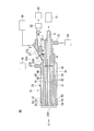
- FIG. 1 is a cross-sectional view schematically showing a schematic configuration of a burner device according to a first embodiment of the present invention.
- a burner device 10 according to a first embodiment includes a combustion burner 11, a first combustion-supporting fluid supply source 12, a fuel fluid supply source 14, and a second combustion-supporting fluid. It has a supply source 16, a raw material powder supply source 18, and a carrier gas supply source 19.
- the combustion burner 11 includes a burner main body 21, a fuel fluid inlet 23, a combustion-supporting fluid inlet 25, a raw material powder inlet pipe 27, and a raw material powder inlet 28.
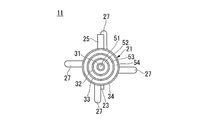
- the burner body 21 includes first to fourth annular members 31 to 34 (a plurality of annular members), whereby a first combustion-supporting fluid supply path 41, a fuel fluid supply path 42, and a raw material powder Supply path 43, second combustion-supporting fluid supply path 44, first combustion-supporting fluid outlet 51, fuel fluid injection outlet 52, raw material powder injection outlet 53, and second combustion-supporting ability And a fluid ejection port 54.
- the first annular member 31 is an annular member having the smallest outer diameter among the first to fourth annular members 31 to 34.
- the first annular member 31 is disposed on the innermost side among the first to fourth annular members 31 to 34.
- the second annular member 32 is arranged outside the first annular member 31 so that a cylindrical space is formed between the second annular member 32 and the first annular member 31.
- the second annular member 32 is a second raw material powder supply path partitioning annular member that partitions the inside of the raw material powder supply path 43.
- the second annular member 32 is configured to be shorter than the first annular member 31.
- the rear end of the second annular member 32 is bent in an L shape and is connected to the outer wall of the first annular member 31.
- the raw material powder introduced from the raw material powder introduction tube 27 collides with the outer wall 32 ⁇ / b> A of the second annular member 32. Therefore, the outer diameter of the portion of the second annular member 32 where the raw material powder collides may be larger than the outer diameter of the portion where the raw material powder does not collide. Thereby, the raw material powder can be further easily dispersed.
- the surface of the portion where the raw material powder collides is separated from another member (for example, a metal annular tube such as SUS (stainless steel) that is not easily worn.
- a metal annular tube such as SUS (stainless steel) that is not easily worn
- An annular tube made of the same material as the raw material powder to be used may be provided. Accordingly, the raw material powder can be easily dispersed by colliding the raw material powder with the other member.
- the influence of damage due to wear can be minimized.
- the third annular member 33 is disposed outside the second annular member 32 so that a cylindrical space is formed between the third annular member 33 and the second annular member 32.
- the third annular member 33 is a first raw material powder supply path partitioning annular member that partitions the outside of the raw material powder supply path 43.
- the third annular member 33 is configured to be shorter than the second annular member 32.
- the rear end of the third annular member 33 is bent in an L shape and is connected to the outer wall of the second annular member 32.
- the fourth annular member 34 is disposed outside the third annular member 33 so that a cylindrical space is formed between the fourth annular member 34 and the second annular member 33.
- the fourth annular member 34 is configured to be shorter than the third annular member 33.
- the rear end of the fourth annular member 34 is bent in an L shape and is connected to the outer wall of the third annular member 33.
- the first to fourth annular members 31 to 34 (a plurality of annular members) are arranged concentrically with respect to the central axis A of the burner body 21.
- the tip surfaces of the first to fourth annular members 31 to 34 are flush with each other.
- a tip 21A of the burner body 21 is constituted by the tips of the first to fourth annular members 31 to 34.
- a flame (not shown) is formed at the tip 21 ⁇ / b> A of the burner body 21.
- the first combustion-supporting fluid supply path 41 is a cylindrical path formed in the first annular member 31.
- the first combustion-supporting fluid supply path 41 is connected to the combustion-supporting fluid supply source 12 that supplies the combustion-supporting fluid.
- the fuel fluid supply path 42 is a cylindrical space formed between the first annular member 31 and the second annular member 32.
- the fuel fluid supply path 42 is connected to the fuel fluid supply source 14 that supplies the fuel fluid via the fuel fluid inlet 23.
- the raw material powder supply path 43 is a cylindrical space formed between the second annular member 32 and the third annular member 33.
- the raw material powder supply path 43 is disposed between the combustion fluid supply path 42 and the second combustion-supporting fluid supply path 44.
- the raw material powder is introduced into the raw material powder supply path 43 via the raw material powder introduction pipe 27.
- the raw material powder supply path 43 is a path for supplying the raw material powder to the raw material powder jet outlet 53.
- the second combustion-supporting fluid supply path 44 is a cylindrical space formed between the third annular member 33 and the fourth annular member 34.
- the second combustion-supporting fluid supply path 44 is connected to the second combustion-supporting fluid supply source 16 that supplies the second combustion-supporting fluid via the combustion-supporting fluid inlet 25.
- the first combustion-supporting fluid supply path 41, the fuel fluid supply path 42, the raw material powder supply path 43, and the second combustion-supporting fluid supply path 44 (a plurality of paths) described above are the center of the burner body 21. They are arranged concentrically with the axis A.
- FIG. 2 is a C view of the combustion burner according to the first embodiment shown in FIG. In FIG. 2, the same components as those of the combustion burner 11 shown in FIG.
- the first combustion-supporting fluid ejection port 51 is configured by the tip of the first annular member 31.
- the first combustion-supporting fluid ejection port 51 is disposed at the tip of the first combustion-supporting fluid supply path 41.
- the first combustion-supporting fluid outlet 51 is integrated with the first combustion-supporting fluid supply path 41.
- the shape of the first combustion-supporting fluid ejection port 51 can be, for example, a cylinder.
- the first combustion-supporting fluid ejection port 51 ejects the first combustion-supporting fluid supplied from the first combustion-supporting fluid supply path 41.
- the fuel fluid ejection port 52 is constituted by the tips of the first and second annular members 31 and 32.
- the fuel fluid ejection port 52 is disposed at the tip of the fuel fluid supply path 42.
- the fuel fluid ejection port 52 is integrated with the fuel fluid supply path 42.
- the fuel fluid outlet 52 ejects the fuel fluid supplied from the fuel fluid supply path 42.
- the raw material powder outlet 53 is constituted by the tips of the second and third annular members 32 and 33.
- the raw material powder jet outlet 53 is disposed at the tip of the raw material powder supply path 43. Thereby, the raw material powder jet outlet 53 is integrated with the raw material powder supply path 43.
- the raw material powder jet outlet 53 ejects the raw material powder supplied from the raw material powder supply path 53.
- the second combustion-supporting fluid ejection port 54 is configured by the tips of the third and fourth annular members 33 and 34.
- the second combustion-supporting fluid ejection port 54 is disposed at the tip of the second combustion-supporting fluid supply path 44.
- the second combustion-supporting fluid outlet 54 is integrated with the second combustion-supporting fluid supply path 44.
- the second combustion-supporting fluid ejection port 54 ejects the second combustion-supporting fluid supplied from the second combustion-supporting fluid supply path 44.
- the fuel fluid outlet 52, the raw material powder outlet 53, and the second combustion-supporting fluid outlet 54 described above have a ring shape (see FIG. 2).
- the area of the raw material powder jet port 53 is maximized by making the raw material powder jet port 53 into a simple ring shape, the dispersibility of the raw material powder can be improved.
- a ring shape is illustrated as an example.
- the shapes of the outlet 52, the raw material powder jet 53, and the second combustion-supporting fluid jet 54 are not limited thereto.
- a plurality of concentric circular holes such as a circle, an ellipse, and a polygon are arranged.
- the fuel fluid jet 52, the raw material powder jet 53, and the second combustion-supporting fluid It may be used as the spout 54.
- the fuel fluid inlet 23 is provided on the outer wall of the second annular member 32 and protrudes from the second annular member 32 in a direction away from the second annular member 32.
- the fuel fluid introduction port 23 is connected to a fuel fluid supply source 14 that supplies fuel fluid.
- the combustion-supporting fluid introduction port 25 is provided on the outer wall of the fourth annular member 34 and protrudes from the fourth annular member 34 in a direction away from the fourth annular member 34.
- the combustion-supporting fluid introduction port 25 is connected to the second combustion-supporting fluid supply source 16 that supplies the second combustion-supporting fluid.
- the raw material powder introduction tube 27 is provided on the outer wall of the third annular member 33 in a state where the raw material powder can be introduced into the raw material powder supply path 43.
- the raw material powder introduction tube 27 protrudes from the third annular member 33 to the outside of the third annular member 33.
- the raw material powder introduction tube 27 is inclined so that the angle ⁇ formed by the central axis B of the raw material powder introduction tube 27 and the outer surface 32a of the second annular member 32 is larger than 0 degree and smaller than 90 degrees. Is arranged. Further, the raw material powder introduction tube 27 is arranged so that the axis B ⁇ b> 1 extending the central axis B of the raw material powder introduction tube 27 does not intersect the central axis A of the burner body 21. This point will be described in detail below.
- the angle ⁇ formed by the central axis B of the raw material powder introduction tube 27 and the outer surface 32a of the second annular member 32 is made larger than 0 degree and smaller than 90 degrees, and further, the raw material powder introduction tube 27 is made.
- the raw material powder introduction tube 27 is arranged so that the axis B1 extending the central axis B of the burner body 21 does not intersect with the central axis A of the burner main body 21, so that the raw material powder is formed on the outer wall 32A of the second annular member 32.
- the material powder can be uniformly dispersed in the circumferential direction (left-right direction) of the raw material powder supply path 43 in the raw material powder supply path 43.
- the raw material powder dispersed from the raw material powder outlet 53 can be ejected, the raw material powder is efficiently used by the flame and / or a high temperature region near the flame (hereinafter referred to as “flame region”). It can be heated well.
- the configuration of the combustion burner 11 does not become complicated. That is, the raw material powder can be efficiently heated by improving the dispersibility of the raw material powder ejected from the raw material powder ejection port 53 with a simple configuration.
- the angle ⁇ formed by the central axis B of the raw material powder introduction tube 27 and the outer surface 32a of the second annular member 32 is 10 degrees or more and less than 60 degrees.
- the angle ⁇ is smaller than 10 degrees, the ratio of the raw material powder that collides with the outer wall 32A of the second annular member 32 decreases.
- the combustion burner 11 is elongated.
- the angle ⁇ is 60 degrees or more, the inside of the raw material powder introduction tube 27 may be clogged with the raw material powder. is there.
- the angle ⁇ formed by the central axis B of the raw material powder introduction tube 27 and the outer surface of the third annular member 33 is 10 degrees or more and less than 45 degrees.
- the angle ⁇ is 45 degrees or more, the raw material powder introduction tube 27 may pulsate, and the dispersibility of the raw material powder may be reduced.
- the angle ⁇ is most preferably 30 degrees.
- the raw material powder introduction tube 27 may have a cylindrical shape or a square cylindrical shape.
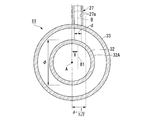
- FIG. 3 is a schematic cross-sectional view of the combustion burner for explaining the positional relationship between the raw material powder introduction tube and the central axis of the burner body.
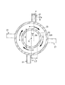
- FIG. 4 is a schematic cross-sectional view of a combustion burner for explaining that the dispersibility of the raw material powder becomes uniform when the raw material powder introduction tube and the central axis of the burner body shown in FIG.
- FIG. 5 illustrates that the dispersibility of the raw material powder deteriorates when a combustion burner having a structure in which the axis extending the central axis of the raw material powder introduction tube intersects the central axis of the burner body is used. It is typical sectional drawing of the combustion burner for performing. 3 and 4 are combustion burners to which the structure of the present invention is applied, and FIG.
- 3 is a combustion burner to which the structure of the present invention is not applied.
- 3 to FIG. 5 only components necessary for explanation are shown.
- 3 to 5 the same components as those of the combustion burner 11 shown in FIGS. 1 and 2 are denoted by the same reference numerals.
- 3 and 4 indicates the distance (hereinafter referred to as “distance x”) between the axis B1 obtained by extending the center axis B of the raw material powder introduction tube 27 and the center axis A of the burner body 21. .
- the inner diameter d of the raw material powder introduction tube 27 (in the case where the shape of the raw material powder introduction tube 27 is a cylindrical shape, the inner diameter, and the shape of the raw material powder introduction tube 27 is a rectangular tube shape)
- the width of the inner wall facing each other) and the outer diameter ⁇ of the second annular member 32 may satisfy the following formula (2) so that the raw material powder introduction pipe 27 and the second annular member 32 are configured. . ⁇ > 2d (2)
- the raw material powder introduction tube 27 When the relationship between the inner diameter d of the raw material powder introduction tube 27 and the outer diameter ⁇ of the second annular member 32 satisfies the above equation (2), the raw material powder is reliably supplied to the outer wall 32A of the second annular member 32. It can be made to collide.
- the inventors further examined that the relationship between the inner diameter d of the raw material powder introduction tube 27 and the outer diameter ⁇ of the second annular member 32 satisfies the following expression (3) and is shown in FIG. Further, the raw material powder introduction tube 27 is arranged so that all the extension of the inner wall surface 27a of the raw material powder introduction tube 27 passes through the range of a distance of 1 / 2 ⁇ 2 from the central axis A of the burner body 21. It is good to arrange. ⁇ > 2 ⁇ 2 ⁇ d (3)
- the raw material powder introduction tube 27 is disposed so that the extension of the inner wall surface 27a of the raw material powder introduction tube 27 passes through the range of a distance of 1 / 2 ⁇ 2 of ⁇ from the central axis A of the burner body 21.
- the raw material powder can be prevented from flowing along the outer wall 32A of the second annular member 32, the raw material powder can be sufficiently dispersed. Thereby, the raw material powder can be sufficiently heated in the flame region.
- the plurality of raw material powder introduction pipes 27 are arranged so that the axis B1 obtained by extending the central axis B of the raw material powder introduction pipe 27 does not intersect the central axis A of the burner body 21.
- FIG. 2 since the collision position of the raw material powder on the outer wall 32A of the second annular member 32 is fixed in the right rotation direction or the left rotation direction, the raw material powder remaining after the collision of the raw material powder Can be eliminated with rotational symmetry, and sufficiently dispersed raw material powder can be ejected from the raw material powder outlet 53 (see FIGS. 1 and 2).
- the raw material powder inlet 28 is provided on the outer wall of the raw material powder inlet tube 27.
- the raw material powder inlet 28 is connected to the raw material powder supply source 18.
- the raw material powder inlet 28 introduces the raw material powder supplied from the raw material powder supply source 18 into the raw material powder introduction tube 27.
- the first combustion-supporting fluid supply source 12 is connected to the first annular member 31 in a state where the first combustion-supporting fluid can be supplied into the first annular member 31.
- a combustion-supporting gas can be used as the first combustion-supporting fluid.
- oxygen, air, or a mixture of these can be used as the first combustion-supporting fluid.
- the fuel fluid supply source 14 is connected to the fuel fluid inlet 23 in a state in which the fuel fluid can be supplied to the fuel fluid inlet 23.
- the fuel fluid include gaseous fuel such as methane gas, propane gas, city gas, LPG (Liquified petroleum), liquid fuel such as kerosene and crude oil, or solid fuel such as pulverized coal conveyed by gas, and a plurality of these. Combinations can be used.
- the second combustion-supporting fluid supply source 16 is connected to the combustion-supporting fluid introduction port 25 in a state where the second combustion-supporting fluid can be supplied into the combustion-supporting fluid introduction port 25.
- a combustion-supporting gas can be used as the second combustion-supporting fluid.
- oxygen, air, or a mixture of these can be used as the combustion-supporting gas.
- the raw material powder supply source 18 is connected to the raw material powder inlet 28 in a state where the raw material powder can be supplied to the raw material powder inlet 28.
- the raw material powder in the present invention is a powder that needs to be heated, and means a solid having a particle size of 10 mm or less or a solid having a Brownian motion of 10 nm or more.
- the raw material powder in the present invention is a gel, a solidified liquid or gas, or a combination thereof, a so-called dust, a granular material, a fine powder, or an ultrafine powder. What was joined, and also those in which these were made into a lump are included.
- the raw material powder in the present invention for example, metal powder, metal compound, ceramic, dust, glass, pulverized coal, solid fuel, food powder such as wheat flour, water, aqueous solution, organic solvent, liquid fuel are solidified. And those obtained by solidifying these raw material powders or raw material droplets, products thereof, or combinations of these. Also included are those whose modes change due to any of the phenomena of combustion, oxidation, reduction, chemical reaction, melting, evaporation, and sublimation by heating the flame formed by the combustion burner 11.
- the carrier gas supply source 19 supplies a carrier gas for transporting the raw material powder into the raw material powder introduction tube 27 as necessary through an inlet (not shown) provided in the raw material powder introduction tube 27.
- a carrier gas for example, a flammable gas such as oxygen or air, a city gas, a flammable gas such as methane and LPG, an inert gas such as nitrogen, or a combination of these gases may be used. it can.
- the raw material powder can be ejected by free fall.
- the carrier gas supply source 19 is not necessary, but even in this case, the carrier gas supply source 19 may be provided as needed to eject the raw material powder with the carrier gas.
- the supply amount (flow rate) of the carrier gas is preferably set so that the ejection speed of the carrier gas ejected from the combustion burner 11 is 5 m / sec or less. More preferably, it should be 2 m / sec or less.
- the carrier gas is ejected at a speed of 5 m / sec or less, which is slower than the ejection speed (10 m / sec or more) of the carrier gas when jetting the raw material powder at a high speed, or 2 m / sec or slower, which is slower
- the ejection speed (10 m / sec or more) of the carrier gas when jetting the raw material powder at a high speed, or 2 m / sec or slower, which is slower
- the angle ⁇ formed by the central axis B of the raw material powder introduction tube 27 and the outer surface 32a of the second annular member 32 is larger than 0 degree and smaller than 90 degrees. Further, by arranging the raw material powder introduction pipe 27 so that the axis B1 extending the central axis B of the raw material powder introduction pipe 27 does not intersect with the central axis A of the burner body 21, the second annular shape is provided.
- the raw material powder collides with the outer wall 32 ⁇ / b> A of the member 32, and the raw material powder can be uniformly dispersed in the raw material powder supply path 43 in the circumferential direction (left-right direction) of the raw material powder supply path 43.
- the raw material powder dispersed from the raw material powder outlet 53 can be ejected, the raw material powder can be efficiently heated by the flame region.
- the configuration of the combustion burner 11 does not become complicated. That is, the raw material powder can be efficiently heated by improving the dispersibility of the raw material powder ejected from the raw material powder ejection port 53 with a simple configuration.
- the first and second combustion-supporting fluid ejection ports 51 and 54 eject the first and second combustion-supporting gas and the fuel fluid ejection port 52 ejects the fuel fluid, whereby the burner body A flame is formed at the tip 21 ⁇ / b> A of 21.
- the raw material powder is introduced into the raw material powder introduction tube 27 through the raw material powder introduction port 28.
- the raw material powder introduction tube is directed to the raw material powder supply path 43 from a direction inclined at an angle ⁇ larger than 0 degree and smaller than 90 degrees and not intersecting the central axis A of the burner body 21.
- the raw material powder introduced in 27 is introduced (raw material powder introduction step).
- the raw material powder introduced into the raw material powder supply path 43 collides with the outer wall 32 ⁇ / b> A of the second annular member 32. Thereby, the raw material powder can be uniformly dispersed in the raw material powder supply path 43.
- the raw material powder supplied through the raw material powder supply path 43 is ejected from the raw material powder ejection port 53, and the raw material powder is heated by a flame (flame region) (heating process).
- the direction is inclined with respect to the cylindrical raw material powder supply path 43 at an angle larger than 0 degree and smaller than 90 degrees, and A raw material powder introduction step for introducing the raw material powder into the raw material powder supply path 43 from a direction not intersecting with the central axis A of the burner body 21, and the raw material powder supplied by the raw material powder supply path 43 as the raw material powder.
- And supplying a raw material powder by causing the raw material powder to collide with the outer wall 32A of the second annular member 32 by having the heating step of jetting the raw material powder by a flame (flame region).
- the raw material powder can be uniformly dispersed in the circumferential direction (left-right direction) of the raw material powder supply path 43.
- the raw material powder dispersed from the raw material powder outlet 53 can be ejected, the raw material powder can be efficiently heated in the flame region.
- FIG. 6 is a cross-sectional view schematically showing a schematic configuration of the burner device according to the second embodiment of the present invention.
- a burner device 60 of the second embodiment has a combustion burner 61 instead of the combustion burner 11 constituting the burner device 10 of the first embodiment, and also distributes raw material powder. Except having the vessel 62, it is configured in the same manner as the burner device 10.
- the combustion burner 61 is configured in the same manner as the combustion burner 11 of the first embodiment, except that it has raw material powder inlets 28-1 and 28-2 instead of the raw material powder inlet 28.
- the raw material powder inlets 28-1 and 28-2 have the same configuration as the raw material powder inlet 28 described in the first embodiment.
- the raw material powder introduction ports 28-1 and 28-2 are provided for one raw material powder introduction pipe 27. That is, two raw material powder inlets (raw material powder inlets 28-1 and 28-2) are provided for one raw material powder inlet tube 27.
- FIG. 6 as an example, a case where two raw material powder introduction ports (in the case of FIG. 6, raw material powder introduction ports 28-1 and 28-2) are provided for one raw material powder introduction tube 27 is illustrated. However, an even number of raw material powder inlets 28-1 and 28-2 may be arranged with respect to one raw material powder inlet tube 27.
- FIG. 7 is a plan view of the raw material powder distributor (a plan view from the upper end side of the raw material powder distributor).
- FIG. 8 is a cross-sectional view in the DD line direction of the raw material powder distributor shown in FIG.
- the raw material powder distributor 62 includes a raw material powder introducing unit 63, a raw material powder distributing unit 64, and raw material powder deriving units 71 to 78 (a plurality of raw material powder deriving units). ).
- the raw material powder introducing portion 63 has a cylindrical shape. Although the shape of the raw material powder introducing
- the raw material powder introducing section 63 is connected to the raw material powder supply source 18 shown in FIG. The raw material powder is supplied from the raw material powder supply source 18 to the raw material powder introducing unit 63.
- the raw material powder distributor 64 is disposed between the raw material powder inlet 63 and the raw material powder outlets 71 to 78.
- the raw material powder distributor 64 has a wider shape as it goes from the raw material powder inlet 63 to the raw material powder outlets 71 to 78.
- the raw material powder distribution unit 64 is a space 64A for distributing the raw material powder to the raw material powder deriving units 71 to 78 (a space having a wider shape from the raw material powder introducing unit 63 toward the raw material powder deriving units 71 to 78). ).
- the raw material powder distribution unit 64 has a bottom plate 64B.
- the raw material powder outlets 71 to 78 are provided on the bottom plate 64 B of the raw material powder distributor 64.
- the raw material powder lead-out portions 71 to 78 are arranged so as to be point-symmetric with respect to the center E of the raw material powder introducing portion 63 (see FIG. 7).
- the raw material powder outlets 71 to 78 are arranged so as to spread outward from the connection position with the raw material powder distributor 64.
- the raw material powder inlets 28-1 and 28-2 (even number of raw material powder inlets) arranged in the same raw material powder introduction pipe 27 are located with respect to the center E of the raw material powder introduction part 63. It is connected to the raw material powder lead-out portions 71 and 72 arranged symmetrically. Specifically, the raw material powder inlet 28-1 is connected to the raw material powder outlet 71, and the raw material powder inlet 28-2 is connected to the raw material powder outlet 72.
- the raw material powder outlets 73 to 78 are connected to a raw material powder inlet (not shown) provided in another raw material powder introduction pipe 27 (not shown) in FIG. It is connected.
- the raw material powder derived radially is supplied to a plurality of raw material powder introduction pipes 27 via the raw material powder inlets 28-1 and 28-2. Can be introduced.
- the facings of the raw material powder deriving units 71 to 78 of the raw material powder distributor 62 for example, a combination of the raw material powder deriving unit 71 and the raw material powder deriving unit 72) or every period N (N is 2 or more)
- N 2 or more
- a plurality (two in the case of FIG. 3) of raw material powder inlets 28-1 and 28-2 are provided for one raw material powder introduction tube 27.
- 2 ⁇ n raw material powder supply sources 18 are prepared for n raw material powder introduction pipes 27 having raw material powder inlets 28-1 and 28-2, and the kth raw material is provided among them.
- the source of the same raw material powder introduction pipe 27 is connected to the path from the raw material powder supply source 18 with a large supply amount of powder and the path from the raw material powder supply source 18 with the smallest supply amount of the raw material powder.
- the raw material powder is transported by connecting to the powder inlets 28-1 and 28-2 (for example, the raw material powder supply source 18 for supplying the largest amount of raw material powder and the smallest amount of raw material)
- a raw material powder supply source 18 for supplying powder is connected to the raw material powder inlets 28-1 and 28-2 so as to be conveyed to the same raw material powder introduction pipe 27, and the second largest amount of powder is supplied.
- the raw material powder source 18 for supplying the raw material powder and the raw material powder source 18 for supplying the second smallest amount of the raw material powder are the same raw material powder.
- the raw material powder can be more dispersed and ejected in the flame region. Therefore, the raw material powder can be efficiently heated. Further, the burner device 60 configured as described above can also obtain the same effects as the burner device 10 of the first embodiment.
- the raw material powder heating method of the second embodiment is supplied from the raw material powder supply source 18 by the raw material powder distributor 62 before the raw material powder introduction step described in the first embodiment. Except for the step of distributing the raw material powder into a plurality of steps, the same method as the raw material powder heating method of the first embodiment can be used.
- the raw material powder heating method of the second embodiment it becomes possible to disperse the raw material powder more efficiently than the raw material powder heating method of the first embodiment.
- the body can be heated more efficiently.
- Example 1 In Experimental Example 1, the experiment was performed using the following combustion burners M1 to M7.
- the combustion burner M1 is designed so that the axis B1 extending the center axis B of the raw material powder introduction pipe 27 and the center axis A of the burner body 21 intersect.
- the distance x (see FIG. 3) between the axis B1 obtained by extending the center axis B of the raw material powder introduction pipe 27 and the center axis A of the burner body 21 is the outer diameter ⁇ of the second annular member 32. Designed to be one-eighth the distance.
- the distance x between the axis B1 obtained by extending the center axis B of the raw material powder introduction pipe 27 and the center axis A of the burner body 21 is a quarter of the outer diameter ⁇ of the second annular member 32. Designed to be a distance away.
- the distance x between the axis B1 obtained by extending the center axis B of the raw material powder introduction pipe 27 and the center axis A of the burner body 21 is 3/8 of the outer diameter ⁇ of the second annular member 32. Designed to be a distance away.
- the distance x between the axis B1 obtained by extending the center axis B of the raw material powder introduction pipe 27 and the center axis A of the burner body 21 is one half of the outer diameter ⁇ of the second annular member 32. Designed to be a distance away.
- the distance x between the axis B1 obtained by extending the center axis B of the raw material powder introduction pipe 27 and the center axis A of the burner body 21 and the outer diameter ⁇ of the second annular member 32 are made equal.
- the distance x between the axis B1 obtained by extending the center axis B of the raw material powder introduction pipe 27 and the center axis A of the burner body 21 is 1.5 times the outer diameter ⁇ of the second annular member 32. did.
- the number of the raw material powder introduction pipes 27 is one, and the outer diameter of the raw material powder introduction pipes 27 is 1 ⁇ 4 of the outer diameter ⁇ of the second annular member 32. Further, in the combustion burners M1 to M7, the thickness of the raw material powder introduction tube 27 is made to be almost negligible with respect to the outer diameter of the raw material powder introduction tube 27. In the combustion burners M1 to M7, the angle ⁇ formed by the central axis B of the raw material powder introduction tube 27 and the outer surface 32a of the second annular member 32 is 30 degrees. In the combustion burners M1 to M7, two raw material powder introduction ports 28-1 are provided in the raw material powder introduction pipe 27.
- a ring-shaped nozzle is used as the raw material powder nozzle 53.
- the combustion burners M1 to M7 are arranged so that the tip 21A of the burner body 21 faces downward (in other words, the central axis A of the burner body 21 is in the vertical direction).
- a method for supplying the raw material powder an experiment was conducted by both a free fall method and an air current conveyance method.
- oxygen is supplied so that the ejection speed from the tip end surface 21A of the burner body 21 is 4 m / sec in the airflow conveyance method, and in the free fall method, from the tip surface 21A of the burner body 21 as clogging prevention.
- Oxygen was supplied so that the ejection speed of the gas was 1.5 m / sec.
- glass cullet having a particle diameter of 1 ⁇ m to 5 mm (D50 to 300 ⁇ m) was used. Except as described above, a configuration similar to that of the burner device 10 shown in FIG. 1 was used.
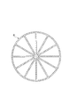
- FIG. 9 is a plan view of the raw material powder receiver.
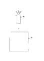
- FIG. 10 schematically shows the positional relationship between the combustion burner and the raw material powder receiver when the amount of the raw material powder ejected from the combustion burner is measured using the raw material powder receiver shown in FIG. FIG.
- the combustion burner M1 is shown as an example of the combustion burner. However, after the measurement of the amount of the raw material powder ejected from the combustion burner M1 is completed, the combustion burners M2 to M7 are sequentially replaced with the combustion burner M1. The ejection amount of the raw material powder was measured.
- any one of the combustion burners M1 to M7 is placed above the raw material powder receiver 81.
- the dispersibility of the raw material powder of each combustion burner M1 to M7 was evaluated.
- the raw material powder receiver 81 has an area (in the case of FIG. 9, 12 areas) equally divided on the circumference, and the amount of the raw material powder dropped into each area Is configured to be able to measure each.
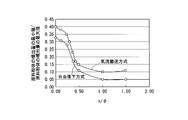
- FIG. 11 shows a case where the raw material powder is supplied by the free-fall method and the air flow conveyance method using the burner device of Experimental Example 1 (the burner device having any one of the combustion burners M1 to M7).
- FIG. 4 is a graph (graph) showing the relationship between (minimum value of raw material powder ejection amount) / (maximum value of raw material powder ejection amount) and (distance x) / (outer diameter ⁇ of second annular member). is there.
- the relationship between the inner diameter d of the raw material powder introduction tube 27 and the outer diameter ⁇ of the second annular member 32 is as follows. All the extensions of the inner wall surface 27a of the raw material powder introduction pipe 27 pass through the range satisfying the equation (4) and within a distance of 1 / 2 ⁇ 2 of ⁇ from the central axis A of the burner body 21 (see FIG. 3). Thus, it was confirmed that it is important to arrange the raw material powder introduction tube 27. ⁇ > 2 ⁇ 2 ⁇ d (4)
- the position of the area showing the maximum value of the raw material powder ejection amount was fixed.
- the area showing the maximum value of the raw material powder ejection amount is indefinite for each number of trials, and the maximum amount of raw material powder ejection amount is approximately symmetrical about the central axis A of the burner body 21. The position of the area showing the value fluctuated.
- Example 2 In Experimental Example 2, the experiment was performed using the following combustion burners N1 to N7.
- the combustion burner N1 is designed so that the axis B1 extending the center axis B of the raw material powder introduction tube 27 and the center axis A of the burner body 21 intersect.
- the distance x (see FIG. 3) between the axis B1 obtained by extending the center axis B of the raw material powder introduction pipe 27 and the center axis A of the burner body 21 is the outer diameter ⁇ of the second annular member 32. Designed to be one-eighth the distance.
- the distance x between the axis B1 obtained by extending the center axis B of the raw material powder introduction pipe 27 and the center axis A of the burner body 21 is a quarter of the outer diameter ⁇ of the second annular member 32. Designed to be a distance away.
- the distance x between the axis B1 obtained by extending the center axis B of the raw material powder introduction pipe 27 and the center axis A of the burner body 21 is 3/8 of the outer diameter ⁇ of the second annular member 32. Designed to be a distance away.
- the distance x between the axis B1 obtained by extending the center axis B of the raw material powder introduction pipe 27 and the center axis A of the burner body 21 is one half of the outer diameter ⁇ of the second annular member 32. Designed to be a distance away.
- the distance x between the axis B1 obtained by extending the center axis B of the raw material powder introduction pipe 27 and the center axis A of the burner body 21 and the outer diameter ⁇ of the second annular member 32 are made equal.
- the distance x between the axis B1 obtained by extending the center axis B of the raw material powder introduction pipe 27 and the center axis A of the burner body 21 is 1.5 times the outer diameter ⁇ of the second annular member 32. did.
- the number of raw material powder introduction pipes 27 is eight, and the eight raw material powder introduction pipes 27 are arranged so as to be rotationally symmetric with respect to the central axis A of the burner body 21.
- the eight raw material powder introduction pipes 27 are arranged so as to be rotationally symmetric with respect to the central axis A of the burner body 21.
- the combustion burners M1 to M7 described in Experimental Example 1 It differs from a combustion burner having only one raw material powder introduction tube 27).
- the same conditions as those of the combustion burners M1 to M7 were used with respect to the outer diameter of the raw material powder introduction tube 27 and the thickness of the raw material powder introduction tube 27.
- the angle ⁇ formed between the central axis B of the raw material powder introduction tube 27 and the outer surface 32a of the second annular member 32 was set to 30 degrees, which is the same as that of the combustion burners M1 to M7.
- two raw material powder introduction ports 28 are provided for one raw material powder introduction tube 27.
- one raw material powder is introduced. Only one raw material powder inlet 28-1 was provided for the tube 27.
- a ring-shaped nozzle is used as the raw material powder nozzle 53.
- the combustion burners N1 to N7 are arranged so that the tip 21A of the burner body 21 faces downward (in other words, the central axis A of the burner body 21 coincides with the vertical direction).
- the raw material powder As a method for supplying the raw material powder, an experiment was conducted by both a free fall method and an air current conveyance method.
- the raw material powder glass cullet having a particle diameter of 1 ⁇ m to 5 mm (D50 to 300 ⁇ m) was used. Except as described above, the same configuration as that of the burner device 10 shown in FIG. 6 was used. That is, in Experimental Example 2, the raw material powder supplied from the raw material powder supply source 18 is distributed by the raw material powder distributor 62 shown in FIGS. Raw material powder was introduced. The eight raw material powder inlets 28-1 and the raw material powder outlets 71 to 78 of the raw material powder distributor 62 were connected in the circumferential order.
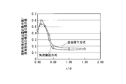
- FIG. 12 shows a case where the raw material powder is supplied by the free-fall method and the air flow conveying method using the burner device of Experimental Example 2 (the burner device having any one of the combustion burners N1 to N7).
- FIG. 4 is a graph (graph) showing the relationship between (minimum value of raw material powder ejection amount) / (maximum value of raw material powder ejection amount) and (distance x) / (outer diameter ⁇ of second annular member). is there.
- Example 3 Using the burner device (see FIG. 6) having the combustion burner N2 having the highest dispersibility in Experimental Example 2, a combustion test is performed under the same conditions as in Experimental Example 2, and a heating test of the raw material powder in the flame region is performed. went. At this time, the raw material powder was supplied by a free-fall method and an air current conveyance method. As the raw material powder, glass cullet having a particle diameter of 1 ⁇ m to 5 mm (D50 to 300 ⁇ m) was used.
- oxygen is supplied to the first combustion-supporting fluid supply path 41 so that the ejection speed from the tip end surface 21A of the burner body 21 is 10 m / sec, and the burner body 21 is supplied to the fuel fluid supply path 42.
- the city gas was supplied so that the ejection speed from the tip surface 21A of the gas was 10 m / sec.
- the jet velocity from the tip surface 21A of the burner body 21 is 1 in the free fall method so that the jet velocity from the tip surface 21A of the burner body 21 is 4 m / sec in the flow conveyance method.
- Oxygen was supplied at a rate of 0.5 m / sec.
- the city gas was supplied to the second combustion-supporting fluid supply path 44 so that the ejection speed from the tip surface 21A of the burner body 21 was 10 m / sec.
- the heat efficiency ⁇ indicating the ratio of the heat energy Q to the raw material powder with respect to the combustion amount I of the city gas was determined using the following equation (5).
- ⁇ Q / I ⁇ 100 (%) (5)
- the heat drop efficiency of the free-fall method was 54%
- the heat transfer efficiency of the airflow conveyance method was 51%.
- Example 4 Using the burner device (see FIG. 6) having the combustion burner N2 having the highest dispersibility in Experimental Example 2, among the eight raw material powder introduction pipes 27, the rotation target is set with respect to the central axis A of the burner body 21.
- the raw material powder was introduced from the four raw material powder introduction pipes 27 arranged. Further, two raw material powder inlets (raw material powder inlets 28-1 and 28-2) are provided for one raw material powder inlet tube 27.
- two raw material powder deriving units (out of the raw material powder deriving units 71 to 78) arranged in a point manner with respect to the center E of the raw material powder introducing unit 63 (see FIG. 7).
- the four raw material powder introduction pipes 27 that are not used were closed.
- Experimental Example 3 using the burner device configured as described above, a combustion test was performed under the same conditions as in Experimental Example 2, and a raw material powder heating test was performed in the flame region. At this time, the raw material powder was supplied by a free-fall method and an air current conveyance method. As the raw material powder, glass cullet having a particle diameter of 1 ⁇ m to 5 mm (D50 to 300 ⁇ m) was used.
- oxygen is supplied to the first combustion-supporting fluid supply path 41 so that the ejection speed from the tip end surface 21A of the burner body 21 is 10 m / sec, and the burner body 21 is supplied to the fuel fluid supply path 42.
- the city gas was supplied so that the ejection speed from the tip surface 21A of the gas was 10 m / sec.
- the jet velocity from the tip surface 21A of the burner body 21 is 1 in the free fall method so that the jet velocity from the tip surface 21A of the burner body 21 is 4 m / sec in the flow conveyance method.
- Oxygen was supplied at a rate of 0.5 m / sec.
- oxygen was supplied to the second combustion-supporting fluid supply path 44 so that the ejection speed from the tip surface 21A of the burner body 21 was 10 m / sec.
- the heat receiving efficiency indicating the ratio of the heat receiving energy to the raw material powder with respect to the combustion amount of the city gas was obtained.
- the heat drop efficiency of the free-fall method was 65%
- the heat transfer efficiency of the airflow conveyance method was 62%.
- Example 5 Using a burner device having a combustion burner N2 (see FIG. 6), the raw material powder inlets 28-1, 28- are arranged so that the raw material powder outlets 71 to 78 are adjacent to each other. 2 was connected. This is different from Experimental Example 4.
- the number of raw material powder introduction pipes 27 increases, the difficulty in designing and producing a combustion burner and the complexity of use increase. Therefore, a plurality of raw material powder inlets 28-1 and 28-2 are connected to the raw material powder. It has been found that the combustion burner arranged in the body introduction pipe 27 is preferable to the combustion burner in which the number of raw material powder introduction pipes 27 is simply increased.
- Example 6 (Experimental example 6) In Experimental Example 6, three raw material powder inlets (similar to the raw material powder inlets 28-1 and 28-2) are respectively provided for the four raw material powder inlet pipes 27 of the combustion burner N2 used in Experimental Example 4. A combustion burner provided with three raw material powder inlets having a different configuration was used.
- raw material powder distributor 62 twelve raw material powder derivation units (raw material powder derivation units having the same configuration as the raw material powder derivation units 71 to 78) were used. Further, in the circumferential direction of the raw material powder distributor 64, the raw material powder lead-out portions arranged in four jumps were connected to three raw material powder inlets arranged in the same raw material powder introduction pipe 27.
- Example 7 The dispersibility of the raw material powder of the raw material powder distributor 62 used in Experimental Examples 2 to 5 was confirmed.
- the value of (the minimum value of the raw material powder ejection amount) / (the maximum value of the raw material powder ejection amount) is 0.6.
- the value of (minimum value of raw material powder ejection amount) / (maximum value of raw material powder ejection amount) is 0. It was confirmed that the difference between the minimum amount of the raw material powder and the maximum amount of the raw material powder was considerably small.
- the value of (minimum value of the ejection amount of the raw material powder) / (maximum value of the ejection amount of the raw material powder) in Experimental example 5 using the raw material powder distributor 62 with the same connection method as in Experimental example 4 is The free fall method is 0.88, and the air current conveyance method is 0.8, and the value of (Minimum value of raw material powder ejection amount) / (Maximum value of raw material powder ejection amount) in Experimental Example 2 is free.
- the drop method was 0.60, and the airflow conveyance method was 0.54. From this, using the same connection method as in Experimental Example 4 improves the dispersibility of the raw material powder as compared to the case where the raw material powder distributor 62 is used in the connection method of Experimental Example 2. It could be confirmed.
- Example 8 The dispersibility of the raw material powder of the raw material powder distributor 62 (the raw material powder distributor having 12 raw material powder outlets) used in the connection method of Experimental Example 6 was confirmed.
- the raw material powder distributor 62 of Experimental Example 6 when the raw material powders ejected from the 12 raw material powder outlets are added together ((minimum value of the ejection amount of the raw material powders) / (ejection of the raw material powders) The value of the maximum amount was 0.55.
- the raw material powder distributor 62 of Experimental Example 6 As in Experimental Example 6, it is ejected from three raw material powder deriving portions arranged in four jumps in the circumferential direction of the raw material powder distributor 64.
- the value of (minimum value of the ejection amount of the raw material powder) / (maximum value of the ejection amount of the raw material powder) when adding up the ejection amount of the raw material powder was 0.98.
- Example 9 In Experimental Example 9, in the combustion burner N2 described in Experimental Example 4, the combustion burners P1 to P10 in which the inclination angle (angle ⁇ shown in FIG. 6) of the raw material powder introduction pipe 27 is changed, and the combustion burner N2 (the angle ⁇ is 30 degrees), and the same experiment as in Experiment Example 4 was performed.
- the angle ⁇ is 90 degrees, and in the combustion burner P2, the angle ⁇ is 80 degrees. In the combustion burner P3, the angle ⁇ is 70 degrees, and in the combustion burner P4, the angle ⁇ is 60 degrees. In the combustion burner P5, the angle ⁇ is 50 degrees, and in the combustion burner P6, the angle ⁇ is 40 degrees. In the combustion burner P7, the angle ⁇ is 20 degrees, and in the combustion burner P8, the angle ⁇ is 10 degrees. In the combustion burner P9, the angle ⁇ was 5 degrees. Furthermore, a combustion burner P10 was prepared in which the angle ⁇ was 0 degrees, that is, parallel to the central axis A of the burner main body 21, and the raw material powder introduction tube 27 was installed on the burner.
- the dispersibility of the raw material powders is the same in the combustion burners P1 to P8 and N2, and the heat receiving efficiency is within the range of 61 ⁇ 1%. There wasn't. However, in the combustion burners P9 and P10, both dispersibility and heat receiving efficiency are lowered. In addition, during the combustion test of the combustion burners P9 and P10, four streaky powder flows were confirmed from the raw material powder jet nozzle.
- the combustion burner P1 is clogged immediately after the start of the test in the raw material powder introduction pipe 27, and the combustion burners P2 and P3 can be used continuously for a long time or the supply amount can be reduced. When it was increased, clogging occurred.
- the present invention is applicable to a combustion burner, a burner device, and a raw material powder heating method for heating powder (raw material powder).
- first 4 annular members 41 ... first combustion-supporting fluid supply path, 42 ... fuel fluid supply path, 43 ... raw material powder supply path, 44 ... second combustion-supporting fluid supply path, 51 ... first support Flammable fluid jet, 52 ... Fuel fluid jet, 53 ... Raw material powder jet, 54 ... Second combustion-supporting fluid jet Mouth, 62 ... Raw material powder distributor, 63 ... Raw material powder introduction part, 64 ... Raw material powder distribution part, 64A ... Space, 64B ... Bottom plate, 71 to 78 ... Raw material powder lead-out part, 81 ... Raw material powder receiver Vessel, A, B ... center axis, B1 ... axis, d ... inner diameter, E ... center, x ... distance, ⁇ ... angle, ⁇ ... outer diameter
Landscapes
- Engineering & Computer Science (AREA)
- Chemical & Material Sciences (AREA)
- Combustion & Propulsion (AREA)
- Mechanical Engineering (AREA)
- General Engineering & Computer Science (AREA)
- Gas Burners (AREA)
- Pre-Mixing And Non-Premixing Gas Burner (AREA)
- Cosmetics (AREA)
- Furnace Details (AREA)
- Nozzles (AREA)
Abstract
Description
火炎を対象物に直接当てて加熱する方法は、火炎の輻射熱により間接的に対象物を加熱する方法と比較して、エネルギーの利用効率が高いというメリットを有する。
特許文献2~5に開示された燃焼バーナは、燃焼バーナの中心またはその近傍(以下、「燃焼バーナの中心部」という)に、粉体噴出口が配置されている。
燃焼バーナの火炎領域を通過する粉体が偏在した場合、粉体の密度の高い部分では十分に粉体が加熱されず、逆に粉体の密度の低い部分では火炎の熱が粉体の加熱に十分に活用されないといった状況が発生して、燃焼バーナのエネルギーの利用効率が低下してしまう。
しかしながら、特許文献2~4に開示された燃焼バーナでは、燃焼バーナの中心部に粉体の噴出口が配置されているため、粉体が偏在した状態で火炎領域を通過してしまう。このため、粉体を加熱しづらく、非効率であった。
したがって、円周上に粉体噴出口を配置した多重管の燃焼バーナを用いる場合でも、その効果を発揮するためには、粉体を円周上に均一に分散させた状態で噴出させる必要がある。
上記理由から、粉体を加熱する場合において、気体の供給量を大きくして、粉体を分散させる方法は非効率な方法と言える。
さらには、気流に高い圧力を印加する必要があるため、途中の配管、機器、及び燃焼バーナを長大にする必要がある。このため、配管が詰まる恐れがあった。
このような理由から、多くの量の搬送用の気体を用いて、粉体を分散させる方法は、非現実的であった。
だからといって、長大な機構や、複雑繊細な構造を燃焼バーナが有することは、経済性、操作性が大幅に悪化し、粉体が詰まる原因となるため、非現実的である。
(1)少なくとも、火炎を形成するバーナ本体と、2つ以上の原料紛体導入管とを具備する燃焼バーナであって、
上記バーナ本体は、原料粉体を供給する原料粉体供給経路、および該原料粉体供給経路の内側に設けられた1つ以上の経路を含む、同心円状に配置された複数の環状部材により形成された複数の経路と、上記原料粉体供給経路により供給された上記原料粉体を噴出する原料粉体噴出口および原料紛体噴出口の内側に位置する複数の噴出口とを有し、
上記原料紛体供給経路は、当該経路の外側を区画する第1の原料粉体供給経路区画用環状部材と、当該経路の内側を区画する第2の原料粉体供給経路区画用環状部材とにより形成され、
上記2つ以上の原料粉体導入管は、上記第1の原料粉体供給経路区画用環状部材に設けられ、該原料粉体導入管の中心軸を延在させた軸が上記バーナ本体の中心軸と交わらないようにすると共に、上記原料粉体導入管の中心軸と前記第2の原料粉体供給経路区画用環状部材の外面との成す角度が0度よりも大きくかつ90度よりも小さくなるように設けると共に、上記バーナ本体の中心軸に対して回転対称となるように配置されていることを特徴とする燃焼バーナ。
φ>2d・・・(1)
よって、本発明の燃焼バーナによれば、簡便な構成により、原料粉体噴出口から噴出させる原料粉体の分散性を向上させることで、原料粉体の加熱を効率良く行うことができる。
図1は、本発明の第1の実施の形態に係るバーナ装置の概略構成を模式的に示す断面図である。
図1を参照するに、第1の実施の形態のバーナ装置10は、燃焼バーナ11と、第1の支燃性流体供給源12と、燃料流体供給源14と、第2の支燃性流体供給源16と、原料粉体供給源18と、キャリアガス供給源19とを有する。
バーナ本体21は、第1ないし第4の環状部材31~34(複数の環状部材)を具備し、これにより第1の支燃性流体供給経路41と、燃料流体供給経路42と、原料粉体供給経路43と、第2の支燃性流体供給経路44と、第1の支燃性流体噴出口51と、燃料流体噴出口52と、原料粉体噴出口53と、第2の支燃性流体噴出口54とを有する。
第2の環状部材32は、第1の環状部材31よりも長さが短くなるように構成されている。第2の環状部材32の後端は、L字形状に折り曲げられており、第1の環状部材31の外壁と接続されている。
そこで、第2の環状部材32のうち、原料粉体が衝突する部分の外径を、原料粉体が衝突しない部分の外径よりも大きくしてもよい。これにより、原料粉体をさらに分散させやすくすることができる。
第3の環状部材33は、第2の環状部材32よりも長さが短くなるように構成されている。第3の環状部材33の後端は、L字形状に折り曲げられており、第2の環状部材32の外壁と接続されている。
燃料流体供給経路42は、第1の環状部材31と第2の環状部材32との間に形成された筒状の空間である。燃料流体供給経路42は、燃料流体導入口23を介して、燃料流体を供給する燃料流体供給源14と接続されている。
原料粉体供給経路43には、原料粉体導入管27を介して、原料粉体が導入される。原料粉体供給経路43は、原料粉体噴出口53に原料粉体を供給する経路である。
第1の支燃性流体噴出口51の形状は、例えば、円柱とすることができる。第1の支燃性流体噴出口51は、第1の支燃性流体供給経路41により供給された第1の支燃性流体を噴出させる。
燃料流体噴出口52は、燃料流体供給経路42の先端に配置されている。これにより、燃料流体噴出口52は、燃料流体供給経路42と一体とされている。燃料流体噴出口52は、燃料流体供給経路42から供給された燃料流体を噴出させる。
原料粉体噴出口53は、原料粉体供給経路43の先端に配置されている。これにより、原料粉体噴出口53は、原料粉体供給経路43と一体とされている。原料粉体噴出口53は、原料粉体供給経路53から供給された原料粉体を噴出させる。
特に、原料粉体噴出口53を単純なリング状にすることにより、原料粉体噴出口53の面積が最大となるため、原料粉体の分散性を向上させることができる。
例えば、リング状の形状ではなく、円形、楕円形、多角形等の孔が同心円状に複数配置されたものを燃料流体噴出口52、原料粉体噴出口53、及び第2の支燃性流体噴出口54として用いてもよい。
原料粉体導入管27は、原料粉体導入管27の中心軸Bと第2の環状部材32の外面32aとの成す角度θが0度よりも大きくかつ90度よりも小さい角度で傾斜するように配置されている。
また、原料粉体導入管27は、原料粉体導入管27の中心軸Bを延在させた軸B1がバーナ本体21の中心軸Aと交わらないように配置されている。なお、この点については以下に詳細に説明する。
つまり、簡便な構成により、原料粉体噴出口53から噴出させる原料粉体の分散性を向上させることで、原料粉体の加熱を効率良く行うことができる。
角度θが10度よりも小さいと、第2の環状部材32の外壁32Aに衝突する原料粉体の割合が少なくなってしまう。また、燃焼バーナ11を先端21Aが下向きとなるようにして、原料粉体を加熱する場合、角度θが10度よりも小さいと、燃焼バーナ11が長尺化してしまう。
また、燃焼バーナ11を先端21Aが下向きとなるようにして、原料粉体を加熱する場合、角度θが60度以上になると、原料粉体導入管27内が原料粉体により目詰まりする恐れがある。
角度θが45度以上になると、原料粉体導入管27が脈動する恐れがあるため、原料粉体の分散性が低下する恐れがある。
原料粉体導入管27の形状は、円筒形状でもよいし、四角の筒形状でもよい。
図4は、図3に示す原料粉体導入管とバーナ本体の中心軸との位置関係のときに、原料粉体の分散性が均一化することを説明するための燃焼バーナの模式的な断面図である。
図5は、原料粉体導入管の中心軸を延在させた軸とバーナ本体の中心軸とが交わる構造とされた燃焼バーナを用いた際に原料粉体の分散性が悪化することを説明するための燃焼バーナの模式的な断面図である。
つまり、図3及び図4は、本発明の構造が適用された燃焼バーナであり、図5は、本発明の構造が適用されていない燃焼バーナである。
図3~図5では、説明に必要な構成要素のみ図示する。また、図3~図5において、図1及び図2に示す燃焼バーナ11と同一構成部分には同一符号を付す。図3及び図4に示すxは、原料粉体導入管27の中心軸Bを延長させた軸B1とバーナ本体21の中心軸Aとの距離(以下、「距離x」という)を示している。
φ>2d・・・(2)
φ>2√2×d・・・(3)
このように、回転対称となるように、第3の環状部材33に2つ以上の原料粉体導入管27を設けることにより、残存する原料粉体の偏りを小さくして、回転対称に平均化することが可能となる。
これにより、原料粉体をより分散させた状態で火炎領域へ投入することが可能となるので、さらに効率良く粉体を加熱できる。
このため、複数の原料粉体導入管27を回転対称に配置したとしても、隣接する原料粉体導入管27の偏りが重なり合って、原料粉体の分散性が低下することがある。
また、燃焼バーナ11が形成する火炎の加熱により、燃焼、酸化、還元、化学反応、溶融、蒸発、昇華のいずれかの現象により様態が変化するものも含まれる。
つまり、簡便な構成により、原料粉体噴出口53から噴出させる原料粉体の分散性を向上させることで、原料粉体の加熱を効率良く行うことができる。
始めに、第1及び第2の支燃性流体噴出口51,54から第1及び第2の支燃性ガスを噴出させると共に、燃料流体噴出口52から燃料流体を噴出させることで、バーナ本体21の先端21Aに火炎を形成する。
次いで、0度よりも大きくかつ90度よりも小さい角度θで傾斜した方向で、かつバーナ本体21の中心軸Aと交わらない方向から、原料粉体供給経路43に対して、原料粉体導入管27に導入された原料粉体を導入する(原料粉体導入工程)。
次いで、原料粉体供給経路43により供給された原料粉体を原料粉体噴出口53から噴出させて、火炎(火炎領域)により原料粉体を加熱する(加熱工程)。
つまり、簡便な構成により、原料粉体噴出口53から噴出させる原料粉体の分散性を向上させることで、原料粉体の加熱を効率良く行うことができる。
(第2の実施の形態)
図6は、本発明の第2の実施の形態に係るバーナ装置の概略構成を模式的に示す断面図である。図6において、図1に示す第1の実施の形態のバーナ装置10と同一構成部分には同一符号を付す。
原料粉体導入部63は、筒状とされている。原料粉体導入部63の形状は、例えば、円筒とすることができるが、これに限定されない。例えば、原料粉体導入部63の形状は、四角状の筒でもよい。
原料粉体導入部63は、図6に示す原料粉体供給源18と接続されている。原料粉体導入部63には、原料粉体供給源18から原料粉体が供給される。
原料粉体分配部64は、原料粉体導出部71~78に原料粉体を分配する空間64A(原料粉体導入部63から原料粉体導出部71~78に向かうにつれて幅広形状とされた空間)を有する。また、原料粉体分配部64は、底板64Bを有する。
原料粉体導出部71~78は、原料粉体分配部64との接続位置から外側に広がるように配置されている。
具体的には、原料粉体投入口28-1は、原料粉体導出部71と接続され、原料粉体投入口28-2は、原料粉体導出部72と接続されている。
また、原料粉体分配器62の原料粉体導出部71~78の対面同士(例えば、原料粉体導出部71と原料粉体導出部72の組合せ)、あるいは周期N毎(Nは2以上の整数であり、例えば、N=2のときは、原料粉体導出部71,78,72,77の組合せ)に、分配した原料粉体を同一の原料粉体導入管27の投入口に接続して搬送することにより、原料粉体分配器62による点対称の偏りを解消することが可能となるため、原料粉体供給源18が1つの場合でも、各原料粉体導入管27に原料粉体を均等に供給することができる。
また、上記構成とされたバーナ装置60は、第1の実施の形態のバーナ装置10と同様な効果も得ることができる。
第2の実施の形態の原料粉体加熱方法は、第1の実施の形態で説明した原料粉体導入工程の前に、原料粉体分配器62により、原料粉体供給源18から供給された原料粉体を複数に分配する工程を有すること以外は、第1の実施の形態の原料粉体加熱方法と同様な手法により行うことができる。
実験例1では、下記燃焼バーナM1~M7を用いて実験を行った。
ここで、図1を参照して、各燃焼バーナM1~M7の構成について説明する。
燃焼バーナM1では、原料粉体導入管27の中心軸Bを延在させた軸B1とバーナ本体21の中心軸Aが交わるように設計した。
燃焼バーナM2では、原料粉体導入管27の中心軸Bを延長させた軸B1とバーナ本体21の中心軸Aとの距離x(図3参照)が、第2の環状部材32の外径φの8分の1の距離離れているように設計した。
燃焼バーナM4では、原料粉体導入管27の中心軸Bを延長させた軸B1とバーナ本体21の中心軸Aとの距離xが、第2の環状部材32の外径φの8分の3の距離離れているように設計した。
燃焼バーナM6では、原料粉体導入管27の中心軸Bを延長させた軸B1とバーナ本体21の中心軸Aとの距離xと第2の環状部材32の外径φとを等しくした。
燃焼バーナM7では、原料粉体導入管27の中心軸Bを延長させた軸B1とバーナ本体21の中心軸Aとの距離xが第2の環状部材32の外径φの1.5倍とした。
また、燃焼バーナM1~M7では、原料粉体導入管27の肉厚を原料粉体導入管27の外径に対してほとんど無視できる厚さとした。
また、燃焼バーナM1~M7では、原料粉体導入管27の中心軸Bと第2の環状部材32の外面32aとの成す角度θは、30度とした。
また、燃焼バーナM1~M7では、原料粉体導入管27に2つの原料粉体導入口28-1を設けた。
燃焼バーナM1~M7は、バーナ本体21の先端21Aが下向きとなるように(言い換えれば、バーナ本体21の中心軸Aが鉛直方向となるように)配置した。
原料粉体の供給方法としては、自由落下方式と気流搬送方式との両方で実験を行った。
キャリアガスとして、気流搬送方式ではバーナ本体21の先端面21Aからの噴出速度が4m/secとなるように酸素を供給し、自由落下方式では、目詰まり防止として、バーナ本体21の先端面21Aからの噴出速度が1.5m/secとなるように酸素を供給した。
原料粉体としては、1μm~5mmの粒径(D50~300μm)とされたガラスカレットを用いた。
上記説明したこと以外は、図1に示すバーナ装置10と同様な構成を用いた。
図10では、燃焼バーナの一例として、燃焼バーナM1を図示したが、燃焼バーナM1の原料粉体の噴出量の測定が終了後は、燃焼バーナM1に替えて、順次、燃焼バーナM2~M7の原料粉体の噴出量の測定を行った。
図9に示すように、原料粉体受け器81は、円周に等分に分割されたエリア(図9の場合、12のエリア)を有し、各エリアに投下された原料粉体の量をそれぞれ測定可能な構成とされている。
また、上記燃焼バーナM1~M7の各原料粉体噴出口53から噴出された原料粉体の噴出量の最大値に対する最小値の割合((原料粉体の噴出量の最小値)/(原料粉体の噴出量の最大値))を原料粉体の分散性の指標とした。
なお、(原料粉体の噴出量の最小値)/(原料粉体の噴出量の最大値)が1に近づくほど、原料粉体の分散性が良好なことを意味する。
図11を参照するに、燃焼バーナM1~M3の分散性は、ほとんど等しい結果となった。燃焼バーナM4は、燃焼バーナM1~M3の分散性と比較して、分散性が急激に低下することが確認できた。
また、燃焼バーナM6,M7では、原料粉体が偏在化した筋状の流れが噴出口から噴出される様子が目視にて確認できた。燃焼バーナM5では、弱い筋状の原料粉体の流れが確認された。燃焼バーナM1~M4において、このような原料粉体の流れは確認できなかった。
φ>2√2×d・・・(4)
実験例2では、下記燃焼バーナN1~N7を用いて実験を行った。
ここで、図3及び図6を参照して、各燃焼バーナN1~N7の構成について説明する。
燃焼バーナN1では、原料粉体導入管27の中心軸Bを延在させた軸B1とバーナ本体21の中心軸Aが交わるように設計した。
燃焼バーナN2では、原料粉体導入管27の中心軸Bを延長させた軸B1とバーナ本体21の中心軸Aとの距離x(図3参照)が、第2の環状部材32の外径φの8分の1の距離離れているように設計した。
燃焼バーナN4では、原料粉体導入管27の中心軸Bを延長させた軸B1とバーナ本体21の中心軸Aとの距離xが、第2の環状部材32の外径φの8分の3の距離離れているように設計した。
燃焼バーナN6では、原料粉体導入管27の中心軸Bを延長させた軸B1とバーナ本体21の中心軸Aとの距離xと第2の環状部材32の外径φとを等しくした。
燃焼バーナN7では、原料粉体導入管27の中心軸Bを延長させた軸B1とバーナ本体21の中心軸Aとの距離xが第2の環状部材32の外径φの1.5倍とした。
燃焼バーナN1~N7では、8つの原料粉体導入管27をバーナ本体21の中心軸Aに対して回転対称となるように配置させたことが、実験例1で説明した燃焼バーナM1~M7(1つの原料粉体導入管27のみを有する燃焼バーナ)と異なる。
燃焼バーナN1~N7において、原料粉体導入管27の外径や原料粉体導入管27の肉厚に関しては、燃焼バーナM1~M7と同じ条件を用いた。
実験例1で使用した燃焼バーナM1~M7では、1つの原料粉体導入管27に対して2つの原料粉体導入口28を設けたが、燃焼バーナN1~N7では、1つの原料粉体導入管27に対して1つの原料粉体導入口28-1のみを設けた。
燃焼バーナN1~N7は、バーナ本体21の先端21Aが下向きとなるように(言い換えれば、バーナ本体21の中心軸Aが鉛直方向と一致するように)配置した。
原料粉体としては、1μm~5mmの粒径(D50~300μm)とされたガラスカレットを用いた。
上記説明したこと以外は、図6に示すバーナ装置10と同様な構成を用いた。つまり、実験例2では、原料粉体供給源18から供給された原料粉体を図7及び図8に示す原料粉体分配器62により分配した後、8つの原料粉体導入口28-1に原料粉体を導入した。
8つの原料粉体導入口28-1と原料粉体分配器62の原料粉体導出部71~78とは、円周方向の配列順で接続させた。
その後、燃焼バーナN1~N7の各噴出口から噴出された噴出量の最大値に対する最小値の割合によって、各燃焼バーナN1~N7の分散性を評価した。
これは、バーナ本体21の中心軸Aを中心として対称に、残存する原料粉体の偏りが流れる位置が変動するため、隣り合う位置に配置された原料粉体導入管28-1の原料粉体の偏りが重複する状況が発生したためと考えられる。
各実験での設定条件や、バーナ装置の違いによる粉体分散性の比較のため、図13に各実験例における原料粉体の噴出量の最小値と最大値の比((原料粉体の噴出量の最小値)/(原料粉体の噴出量の最大値))を示す。前述の通り、この値が1に近づくほど、分散性が良好であることを示す。
なお、図13には、自由落下方式と気流搬送方式の実験結果を併記した。図13中、実験例2と示したのは燃焼バーナN2を用いた結果である。
実験例2で最も分散性の高かった燃焼バーナN2を有するバーナ装置(図6参照)を用いて、実験例2と同様の条件で燃焼試験を行い、火炎領域での原料粉体の加熱試験を行った。このとき、原料粉体は、自由落下方式と気流搬送方式とで供給した。
原料粉体としては、1μm~5mmの粒径(D50~300μm)とされたガラスカレットを用いた。
原料粉体供給経路43には、流搬送方式ではバーナ本体21の先端面21Aからの噴出速度が4m/secとなるように、自由落下方式ではバーナ本体21の先端面21Aからの噴出速度が1.5m/secとなるように酸素を供給した。また、第2の支燃性流体供給経路44には、バーナ本体21の先端面21Aからの噴出速度が10m/secとなるように都市ガスを供給した。
η=Q/I×100(%)・・・(5)
その結果、実験例3において、自由落下方式の着熱効率は、54%であり、気流搬送方式の着熱効率は、51%であった。
実験例2で最も分散性の高かった燃焼バーナN2を有するバーナ装置(図6参照)を用いて、8つの原料粉体導入管27のうち、バーナ本体21の中心軸Aに対して回転対象に配置された4つの原料粉体導入管27から原料粉体を導入した。
また、1つの原料粉体導入管27に対して、2つの原料粉体導入口(原料粉体導入口28-1,28-2)を設けた。
使用しない4つの原料粉体導入管27については、閉止させた。
原料粉体としては、1μm~5mmの粒径(D50~300μm)とされたガラスカレットを用いた。
原料粉体供給経路43には、流搬送方式ではバーナ本体21の先端面21Aからの噴出速度が4m/secとなるように、自由落下方式ではバーナ本体21の先端面21Aからの噴出速度が1.5m/secとなるように、酸素を供給した。また、第2の支燃性流体供給経路44には、バーナ本体21の先端面21Aからの噴出速度が10m/secとなるように酸素を供給した。
その結果、実験例4では、自由落下方式の着熱効率が65%であり、気流搬送方式の着熱効率が62%であった。
燃焼バーナN2を有するバーナ装置(図6参照)を用い、原料粉体導出部71~78のうち、対面する原料粉体導出部が隣接するように、原料粉体導入口28-1,28-2と接続させた。この点が、実験例4とは異なる。
その結果、実験例5では、自由落下方式の着熱効率が63%であり、気流搬送方式の着熱効率が60%であった。
実験例6では、実験例4で使用した燃焼バーナN2の4つの原料粉体導入管27に対して、それぞれ3つの原料粉体導入口(原料粉体導入口28-1,28-2と同様な構成とされた3つの原料粉体導入口)を設けた燃焼バーナを用いた。
その結果、実験例6では、自由落下方式の着熱効率が65%、気流搬送方式の着熱効率が62%であった。
実験例2~5で使用した原料粉体分配器62の原料粉体の分散性について確認した。
その結果、8つの原料粉体導出部71~78を有する原料粉体分配器62において、(原料粉体の噴出量の最小値)/(原料粉体の噴出量の最大値)の値は、0.6であった。
実験例2,3では、原料粉体の低い分散性が影響したと思われる。
しかし、実験例4で説明した接続方法で原料粉体分配器62を使用したところ、(原料粉体の噴出量の最小値)/(原料粉体の噴出量の最大値)の値は、0.94であり、原料粉体の噴出量の最小値と原料粉体の噴出量の最大値との差がかなり小さくなることが確認できた。
このことから、実験例4と同じ接続方法で使用することで、実験例2の接続方法で原料粉体分配器62を使用した場合と比較して、原料粉体の分散性が向上することが確認できた。
実験例6の接続方法で使用した原料粉体分配器62(12個の原料粉体導出部を有する原料粉体分配器)の原料粉体の分散性について確認した。
実験例6の原料粉体分配器62において、12個の原料粉体導出部から噴出される原料粉体を合算した際の(原料粉体の噴出量の最小値)/(原料粉体の噴出量の最大値)の値は、0.55であった。
この結果が、実験例4と実験例6とにおいて、原料粉体の分散性及び着熱効率に大きな差が生じなかった原因と思われる。
実験例9では、実験例4で説明した燃焼バーナN2において、原料粉体導入管27の傾斜角度(図6に示す角度θ)を変更した燃焼バーナP1~P10と、燃焼バーナN2(角度θが30度)とを用いて、実験例4と同様な実験を行った。
燃焼バーナP5では、角度θを50度とし、燃焼バーナP6では、角度θを40度とした。燃焼バーナP7では、角度θを20度とし、燃焼バーナP8では、角度θを10度とした。燃焼バーナP9では、角度θを5度とした。
さらに、角度θを0度、つまりバーナ本体21の中心軸Aに平行に、バーナ上部に原料粉体導入管27を設置した燃焼バーナP10を用意した。

これは、原料粉体導入管内での粉体の搬送が、一時的な詰まりを繰り返しているためではないかと思われる。
Claims (12)
- 少なくとも、火炎を形成するバーナ本体と、2つ以上の原料紛体導入管とを具備する燃焼バーナであって、
上記バーナ本体は、原料粉体を供給する原料粉体供給経路、および該原料粉体供給経路の内側に設けられた1つ以上の経路を含む、同心円状に配置された複数の環状部材により形成された複数の経路と、上記原料粉体供給経路により供給された上記原料粉体を噴出する原料粉体噴出口および原料紛体噴出口の内側に位置する複数の噴出口とを有し、
上記原料紛体供給経路は、当該経路の外側を区画する第1の原料粉体供給経路区画用環状部材と、当該経路の内側を区画する第2の原料粉体供給経路区画用環状部材とにより形成され、
上記2つ以上の原料粉体導入管は、上記第1の原料粉体供給経路区画用環状部材に設けられ、該原料粉体導入管の中心軸を延在させた軸が上記バーナ本体の中心軸と交わらないようにすると共に、上記原料粉体導入管の中心軸と前記第2の原料粉体供給経路区画用環状部材の外面との成す角度が0度よりも大きくかつ90度よりも小さくなるように設けると共に、上記バーナ本体の中心軸に対して回転対称となるように配置されていることを特徴とする燃焼バーナ。 - 前記原料粉体導入管の中心軸と前記第2の原料粉体供給経路区画用環状部材の外面との成す角度が10度以上で、かつ45度未満であることを特徴とする請求項1記載の燃焼バーナ。
- 前記原料粉体導入管の内径dと前記第2の原料粉体供給経路区画用環状部材の外径φとの関係が下記(1)式を満たすことを特徴とする請求項1または2記載の燃焼バーナ。
φ>2d・・・(1) - 前記複数の噴出口のうち、最も内側に配置された噴出口以外の噴出口の形状が、リング状であることを特徴とする請求項1ないし3のうち、いずれか1項記載の燃焼バーナ。
- 前記原料粉体導入管に設けられ、該原料粉体導入管に前記原料粉体を投入する原料粉体投入口を有することを特徴とする請求項1ないし4のうち、いずれか1項記載の燃焼バーナ。
- 前記原料粉体投入口は、1つの前記原料粉体導入管に対して偶数個配置することを特徴とする請求項5記載の燃焼バーナ。
- 前記複数の経路は、支燃性流体を供給する支燃性流体供給経路、及び燃焼流体を供給する燃焼流体供給経路を含むことを特徴とする請求項1ないし6のうち、いずれか1項記載の燃焼バーナ。
- 前記原料粉体供給経路は、前記支燃性流体供給経路と前記燃焼流体供給経路との間に配置することを特徴とする請求項7記載の燃焼バーナ。
- 請求項6ないし8のうち、いずれか1項記載の燃焼バーナと、
筒状とされた原料粉体導入部と、前記原料粉体投入口に前記原料粉体を導出する複数の原料粉体導出部と、前記原料粉体導入部と複数の前記原料粉体導出部との間に配置されており、前記原料粉体導入部から前記複数の原料粉体導出部に向かうにつれて幅広形状とされ、前記複数の原料粉体導出部に前記原料粉体を分配する空間を有する原料粉体分配部とを含む原料粉体分配器とを有し、
前記複数の原料粉体導出部は、前記原料粉体導入部の中心に対して、点対称となるように配置されており、
同一の前記原料粉体導入管に配置された偶数個の前記原料粉体投入口は、点対称で配置された前記原料粉体導出部と接続されていることを特徴とするバーナ装置。 - 前記複数の原料粉体導出部は、前記原料粉体分配部との接続位置から外側に広がるように配置されていることを特徴とする請求項9記載のバーナ装置。
- 支燃性流体及び燃焼流体を用いて、バーナ装置を構成するバーナ本体の先端に形成される火炎により、原料粉体を加熱する原料粉体加熱方法であって、
円筒状とされた原料粉体供給経路に対して、0度よりも大きくかつ90度よりも小さい角度で傾斜した方向で、かつバーナ本体の中心軸と交わらない方向から、上記原料粉体供給経路に上記原料粉体を導入する原料粉体導入工程と、
上記原料粉体供給経路により供給された上記原料粉体を原料粉体噴出口から噴出させて、前記火炎により前記原料粉体を加熱する加熱工程とを有することを特徴とする原料粉体加熱方法。 - 前記原料粉体導入工程の前に、原料粉体分配器により前記原料粉体を複数に分配する工程を有し、
前記原料粉体導入工程では、前記原料粉体供給経路に、前記原料粉体分配器により分配された前記原料粉体を導入することを特徴とする請求項11記載の原料粉体加熱方法。
Priority Applications (4)
| Application Number | Priority Date | Filing Date | Title |
|---|---|---|---|
| US14/773,879 US9671107B2 (en) | 2013-03-21 | 2014-03-19 | Combustion burner, burner apparatus, and raw material powder-heating method |
| CN201480003610.5A CN104884865B (zh) | 2013-03-21 | 2014-03-19 | 燃烧烧嘴、烧嘴装置及原料粉体加热方法 |
| PH12015502010A PH12015502010A1 (en) | 2013-03-21 | 2015-09-08 | Combustion burner, burner apparatus, and raw material powder-heating method |
| US15/488,729 US10174940B2 (en) | 2013-03-21 | 2017-04-17 | Raw material powder-heating method |
Applications Claiming Priority (2)
| Application Number | Priority Date | Filing Date | Title |
|---|---|---|---|
| JP2013059023A JP6070323B2 (ja) | 2013-03-21 | 2013-03-21 | 燃焼バーナ、バーナ装置、及び原料粉体加熱方法 |
| JP2013-059023 | 2013-03-21 |
Related Child Applications (2)
| Application Number | Title | Priority Date | Filing Date |
|---|---|---|---|
| US14/773,879 A-371-Of-International US9671107B2 (en) | 2013-03-21 | 2014-03-19 | Combustion burner, burner apparatus, and raw material powder-heating method |
| US15/488,729 Division US10174940B2 (en) | 2013-03-21 | 2017-04-17 | Raw material powder-heating method |
Publications (1)
| Publication Number | Publication Date |
|---|---|
| WO2014148546A1 true WO2014148546A1 (ja) | 2014-09-25 |
Family
ID=51580220
Family Applications (1)
| Application Number | Title | Priority Date | Filing Date |
|---|---|---|---|
| PCT/JP2014/057514 Ceased WO2014148546A1 (ja) | 2013-03-21 | 2014-03-19 | 燃焼バーナ、バーナ装置、及び原料粉体加熱方法 |
Country Status (6)
| Country | Link |
|---|---|
| US (2) | US9671107B2 (ja) |
| JP (1) | JP6070323B2 (ja) |
| CN (1) | CN104884865B (ja) |
| PH (1) | PH12015502010A1 (ja) |
| TW (1) | TWI638963B (ja) |
| WO (1) | WO2014148546A1 (ja) |
Families Citing this family (5)
| Publication number | Priority date | Publication date | Assignee | Title |
|---|---|---|---|---|
| JP6580710B2 (ja) * | 2016-07-26 | 2019-09-25 | Jfeスチール株式会社 | 電気炉用助燃バーナー |
| CN111349470B (zh) * | 2018-12-24 | 2021-04-13 | 国家能源投资集团有限责任公司 | 烧嘴和具有该烧嘴的气化炉 |
| CN110500591A (zh) * | 2019-08-09 | 2019-11-26 | 南京绿帝环保能源科技有限公司 | 危险废料的燃料式琉璃态化处理装置及其处理方法 |
| JP7161460B2 (ja) * | 2019-09-27 | 2022-10-26 | 大陽日酸株式会社 | 無機質球状化粒子製造装置 |
| CN115654488B (zh) * | 2022-09-28 | 2026-01-02 | 本钢板材股份有限公司 | 一种球团回转窑燃气烧嘴及其使用方法 |
Citations (13)
| Publication number | Priority date | Publication date | Assignee | Title |
|---|---|---|---|---|
| US4373900A (en) * | 1979-11-23 | 1983-02-15 | Pillard, Inc. | Burner for a kiln |
| JPS59193558U (ja) * | 1983-06-07 | 1984-12-22 | 新日本製鐵株式会社 | 溶射バーナ用粉体供給装置 |
| JPH0369527A (ja) * | 1989-08-08 | 1991-03-25 | Yazaki Corp | 光ファイバ用多孔質母材合成用トーチ |
| JPH0517164A (ja) * | 1991-07-02 | 1993-01-26 | Furukawa Electric Co Ltd:The | ガラス微粒子の合成方法 |
| JPH08240303A (ja) * | 1995-03-03 | 1996-09-17 | Mitsui Eng & Shipbuild Co Ltd | 粉体燃焼バーナ |
| JP2004536008A (ja) * | 2001-05-30 | 2004-12-02 | ピレリ・アンド・チ・ソチエタ・ペル・アツィオーニ | 気相成長法によりガラス光ファイバ予成型品を製造する方法及び装置 |
| JP2006076826A (ja) * | 2004-09-09 | 2006-03-23 | Nippon Chem Ind Co Ltd | 無機質球状化粒子製造用バーナ装置 |
| JP2009092254A (ja) * | 2007-10-04 | 2009-04-30 | Taiyo Nippon Sanso Corp | 無機質球状化粒子製造用バーナー及び無機質球状化粒子の製造方法及び装置 |
| JP2010106132A (ja) * | 2008-10-30 | 2010-05-13 | Babcock Hitachi Kk | 固体燃料ガス化バーナ及び固体燃料ガス化バーナを備えたガス化炉 |
| JP2012096942A (ja) * | 2010-10-29 | 2012-05-24 | Asahi Glass Co Ltd | 気中溶融バーナー、ガラス原料の溶融方法、溶融ガラスの製造方法、ガラスビーズの製造方法、ガラス製品の製造方法、気中溶融装置およびガラス製品の製造装置 |
| JP2012189311A (ja) * | 2011-02-21 | 2012-10-04 | Osaka Gas Co Ltd | 燃焼装置とその運転方法 |
| JP2012207817A (ja) * | 2011-03-29 | 2012-10-25 | Taiyo Nippon Sanso Corp | 燃焼バーナ |
| JP2012250886A (ja) * | 2011-06-03 | 2012-12-20 | Asahi Glass Co Ltd | 溶融ガラスの製造方法、気中溶融バーナー、ガラス溶融炉、ガラスビーズの製造方法、ガラス物品の製造方法、及びガラス物品の製造装置 |
Family Cites Families (30)
| Publication number | Priority date | Publication date | Assignee | Title |
|---|---|---|---|---|
| US2832401A (en) * | 1951-04-05 | 1958-04-29 | Ernest E Lail | Open hearth burner |
| DE3027587A1 (de) | 1980-07-21 | 1982-02-25 | Klöckner-Humboldt-Deutz AG, 5000 Köln | Brenner fuer feste brennstoffe |
| JPS59193558A (ja) | 1983-04-15 | 1984-11-02 | Tdk Corp | 光カ−ド |
| DE3518080A1 (de) * | 1985-05-20 | 1986-11-20 | Stubinen Utveckling AB, Stockholm | Verfahren und vorrichtung zum verbrennen fluessiger und/oder fester brennstoffe in pulverisierter form |
| JP2532584B2 (ja) | 1988-06-09 | 1996-09-11 | 日揮株式会社 | 旋回流型燃焼炉 |
| US5019686A (en) | 1988-09-20 | 1991-05-28 | Alloy Metals, Inc. | High-velocity flame spray apparatus and method of forming materials |
| US5178533A (en) * | 1989-10-04 | 1993-01-12 | Enterprise Generale De Chauffage Industries Pillard | Process for exploiting a burner and burners for a rotary tubular furnance |
| US5513583A (en) * | 1994-10-27 | 1996-05-07 | Battista; Joseph J. | Coal water slurry burner assembly |
| CA2162244C (en) * | 1994-11-14 | 1999-04-27 | Hideaki Oota | Pulverized coal combustion burner |
| JP3688944B2 (ja) | 1999-08-30 | 2005-08-31 | 大同特殊鋼株式会社 | 焼却飛灰溶融処理用酸素バーナ |
| US6315551B1 (en) * | 2000-05-08 | 2001-11-13 | Entreprise Generale De Chauffage Industriel Pillard | Burners having at least three air feed ducts, including an axial air duct and a rotary air duct concentric with at least one fuel feed, and a central stabilizer |
| WO2004103548A1 (ja) | 2003-05-23 | 2004-12-02 | Tdk Corporation | 球状粉末製造装置、粉末処理用バーナ、球状粉末の製造方法、球状酸化物粉末、酸化物粉末 |
| JP4542417B2 (ja) | 2004-11-26 | 2010-09-15 | 新日鉄エンジニアリング株式会社 | 廃棄物溶融炉の可燃性ガスの処理方法 |
| JP4606138B2 (ja) | 2004-11-30 | 2011-01-05 | 花王株式会社 | 無機質球状化粒子製造装置 |
| JP5068493B2 (ja) | 2006-08-10 | 2012-11-07 | 大陽日酸株式会社 | バーナ及び粉体可燃物の燃焼方法並びに冷鉄源の溶解・精錬方法 |
| JP4898393B2 (ja) | 2006-11-09 | 2012-03-14 | 三菱重工業株式会社 | バーナ構造 |
| EP2087285A4 (en) * | 2006-11-29 | 2016-08-17 | Smidth As F L | BURNER EQUIPPED WITH MEANS FOR CHANGING THE DIRECTION OF FLOW OF A FUEL |
| KR101129628B1 (ko) | 2007-05-30 | 2012-03-27 | 타이요 닛폰 산소 가부시키가이샤 | 무기질 구상화입자 제조용 버너 |
| JP4969464B2 (ja) | 2008-01-08 | 2012-07-04 | 三菱重工業株式会社 | バーナ構造 |
| JP5116505B2 (ja) | 2008-02-21 | 2013-01-09 | 大陽日酸株式会社 | バーナおよびこれを用いる球状化粒子の製造方法 |
| JP4864053B2 (ja) | 2008-08-04 | 2012-01-25 | 大陽日酸株式会社 | 無機質球状化粒子の製造方法 |
| RU2474760C2 (ru) * | 2008-08-29 | 2013-02-10 | Л'Эр Ликид Сосьете Аноним Пур Л'Этюд Э Л'Эксплуатасьон Де Проседе Жорж Клод | Способ генерирования горения посредством горелки в сборе и горелка в сборе |
| JP5335478B2 (ja) | 2009-02-25 | 2013-11-06 | 大陽日酸株式会社 | 金属粒子の製造装置および製造方法 |
| JP5374404B2 (ja) * | 2009-12-22 | 2013-12-25 | 三菱重工業株式会社 | 燃焼バーナおよびこの燃焼バーナを備えるボイラ |
| AU2011300475B2 (en) * | 2010-09-09 | 2014-11-20 | General Electric Technology Gmbh | An assembly for fossil fuel distribution |
| US9657944B2 (en) * | 2010-09-09 | 2017-05-23 | General Electric Technology Gmbh | Assembly for fossil fuel distribution |
| KR101892683B1 (ko) * | 2010-10-01 | 2018-08-29 | 에어 프로덕츠 앤드 케미칼스, 인코오포레이티드 | 고체 연료의 가스화용 버너 |
| US8915731B2 (en) * | 2010-12-30 | 2014-12-23 | L'air Liquide Societe Anonyme Pour L'etude Et L'exploitation Des Procedes Georges Claude | Flameless combustion burner |
| EP2500640A1 (en) * | 2011-03-16 | 2012-09-19 | L'AIR LIQUIDE, Société Anonyme pour l'Etude et l'Exploitation des Procédés Georges Claude | Low NOx combustion process and burner therefor |
| US9709269B2 (en) * | 2014-01-07 | 2017-07-18 | Air Products And Chemicals, Inc. | Solid fuel burner |
-
2013
- 2013-03-21 JP JP2013059023A patent/JP6070323B2/ja active Active
-
2014
- 2014-03-18 TW TW103110063A patent/TWI638963B/zh not_active IP Right Cessation
- 2014-03-19 WO PCT/JP2014/057514 patent/WO2014148546A1/ja not_active Ceased
- 2014-03-19 US US14/773,879 patent/US9671107B2/en not_active Expired - Fee Related
- 2014-03-19 CN CN201480003610.5A patent/CN104884865B/zh not_active Expired - Fee Related
-
2015
- 2015-09-08 PH PH12015502010A patent/PH12015502010A1/en unknown
-
2017
- 2017-04-17 US US15/488,729 patent/US10174940B2/en active Active
Patent Citations (13)
| Publication number | Priority date | Publication date | Assignee | Title |
|---|---|---|---|---|
| US4373900A (en) * | 1979-11-23 | 1983-02-15 | Pillard, Inc. | Burner for a kiln |
| JPS59193558U (ja) * | 1983-06-07 | 1984-12-22 | 新日本製鐵株式会社 | 溶射バーナ用粉体供給装置 |
| JPH0369527A (ja) * | 1989-08-08 | 1991-03-25 | Yazaki Corp | 光ファイバ用多孔質母材合成用トーチ |
| JPH0517164A (ja) * | 1991-07-02 | 1993-01-26 | Furukawa Electric Co Ltd:The | ガラス微粒子の合成方法 |
| JPH08240303A (ja) * | 1995-03-03 | 1996-09-17 | Mitsui Eng & Shipbuild Co Ltd | 粉体燃焼バーナ |
| JP2004536008A (ja) * | 2001-05-30 | 2004-12-02 | ピレリ・アンド・チ・ソチエタ・ペル・アツィオーニ | 気相成長法によりガラス光ファイバ予成型品を製造する方法及び装置 |
| JP2006076826A (ja) * | 2004-09-09 | 2006-03-23 | Nippon Chem Ind Co Ltd | 無機質球状化粒子製造用バーナ装置 |
| JP2009092254A (ja) * | 2007-10-04 | 2009-04-30 | Taiyo Nippon Sanso Corp | 無機質球状化粒子製造用バーナー及び無機質球状化粒子の製造方法及び装置 |
| JP2010106132A (ja) * | 2008-10-30 | 2010-05-13 | Babcock Hitachi Kk | 固体燃料ガス化バーナ及び固体燃料ガス化バーナを備えたガス化炉 |
| JP2012096942A (ja) * | 2010-10-29 | 2012-05-24 | Asahi Glass Co Ltd | 気中溶融バーナー、ガラス原料の溶融方法、溶融ガラスの製造方法、ガラスビーズの製造方法、ガラス製品の製造方法、気中溶融装置およびガラス製品の製造装置 |
| JP2012189311A (ja) * | 2011-02-21 | 2012-10-04 | Osaka Gas Co Ltd | 燃焼装置とその運転方法 |
| JP2012207817A (ja) * | 2011-03-29 | 2012-10-25 | Taiyo Nippon Sanso Corp | 燃焼バーナ |
| JP2012250886A (ja) * | 2011-06-03 | 2012-12-20 | Asahi Glass Co Ltd | 溶融ガラスの製造方法、気中溶融バーナー、ガラス溶融炉、ガラスビーズの製造方法、ガラス物品の製造方法、及びガラス物品の製造装置 |
Also Published As
| Publication number | Publication date |
|---|---|
| PH12015502010B1 (en) | 2016-01-11 |
| JP2014185784A (ja) | 2014-10-02 |
| US20160025332A1 (en) | 2016-01-28 |
| CN104884865A (zh) | 2015-09-02 |
| TW201502437A (zh) | 2015-01-16 |
| CN104884865B (zh) | 2016-11-16 |
| US20170219204A1 (en) | 2017-08-03 |
| PH12015502010A1 (en) | 2016-01-11 |
| US10174940B2 (en) | 2019-01-08 |
| US9671107B2 (en) | 2017-06-06 |
| TWI638963B (zh) | 2018-10-21 |
| JP6070323B2 (ja) | 2017-02-01 |
Similar Documents
| Publication | Publication Date | Title |
|---|---|---|
| JP6070323B2 (ja) | 燃焼バーナ、バーナ装置、及び原料粉体加熱方法 | |
| US10477665B2 (en) | Microwave plasma torch generating laminar flow for materials processing | |
| CN102112217B (zh) | 无机质球状化粒子制造用燃烧器 | |
| JP5551633B2 (ja) | 液体燃料の燃焼方法及び燃焼装置 | |
| CN102112395B (zh) | 无机质球状化粒子的制造方法 | |
| TW201925672A (zh) | 一種流體分布器、反應裝置及其應用 | |
| CN104870895B (zh) | 燃烧燃料的方法和用于燃烧燃料的燃烧器 | |
| CN106753575A (zh) | 气化喷嘴 | |
| JP5291748B2 (ja) | 燃焼バーナ | |
| JP5603748B2 (ja) | 無機質球状化粒子製造用バーナ、無機質球状化粒子製造装置、及び無機質球状化粒子の製造方法 | |
| JP2015190731A (ja) | セメントロータリーキルン用燃料燃焼装置 | |
| CN105473217A (zh) | 用于制备乙炔和合成气的装置和方法 | |
| JP5367471B2 (ja) | 無機質球状化粒子製造用バーナ及び無機質球状化粒子製造装置、並びに無機質球状化粒子の製造方法 | |
| JP2016129880A (ja) | 無機質球状化粒子製造装置、及び無機質球状化粒子製造方法 | |
| CN105492411B (zh) | 用于制备乙炔和合成气体的设备和方法 | |
| CN113249145B (zh) | 一种粉浆耦合气化燃烧器 | |
| TW201516365A (zh) | 粉體製造裝置 | |
| JP5887173B2 (ja) | 球状化粒子製造装置及び球状化粒子製造方法 | |
| JP2014234933A (ja) | 球状粒子製造用バーナー | |
| US20160250610A1 (en) | High temperature inlet distributor |
Legal Events
| Date | Code | Title | Description |
|---|---|---|---|
| 121 | Ep: the epo has been informed by wipo that ep was designated in this application |
Ref document number: 14771076 Country of ref document: EP Kind code of ref document: A1 |
|
| WWE | Wipo information: entry into national phase |
Ref document number: 12015502010 Country of ref document: PH |
|
| WWE | Wipo information: entry into national phase |
Ref document number: 14773879 Country of ref document: US |
|
| NENP | Non-entry into the national phase |
Ref country code: DE |
|
| 122 | Ep: pct application non-entry in european phase |
Ref document number: 14771076 Country of ref document: EP Kind code of ref document: A1 |