WO2014147860A1 - 舗装構造体及び舗装構造体の施工方法 - Google Patents
舗装構造体及び舗装構造体の施工方法 Download PDFInfo
- Publication number
- WO2014147860A1 WO2014147860A1 PCT/JP2013/073062 JP2013073062W WO2014147860A1 WO 2014147860 A1 WO2014147860 A1 WO 2014147860A1 JP 2013073062 W JP2013073062 W JP 2013073062W WO 2014147860 A1 WO2014147860 A1 WO 2014147860A1
- Authority
- WO
- WIPO (PCT)
- Prior art keywords
- pavement structure
- power
- magnetic
- power supply
- recess
- Prior art date
Links
Images


Classifications
-
- B—PERFORMING OPERATIONS; TRANSPORTING
- B60—VEHICLES IN GENERAL
- B60L—PROPULSION OF ELECTRICALLY-PROPELLED VEHICLES; SUPPLYING ELECTRIC POWER FOR AUXILIARY EQUIPMENT OF ELECTRICALLY-PROPELLED VEHICLES; ELECTRODYNAMIC BRAKE SYSTEMS FOR VEHICLES IN GENERAL; MAGNETIC SUSPENSION OR LEVITATION FOR VEHICLES; MONITORING OPERATING VARIABLES OF ELECTRICALLY-PROPELLED VEHICLES; ELECTRIC SAFETY DEVICES FOR ELECTRICALLY-PROPELLED VEHICLES
- B60L5/00—Current collectors for power supply lines of electrically-propelled vehicles
- B60L5/005—Current collectors for power supply lines of electrically-propelled vehicles without mechanical contact between the collector and the power supply line
-
- B—PERFORMING OPERATIONS; TRANSPORTING
- B60—VEHICLES IN GENERAL
- B60L—PROPULSION OF ELECTRICALLY-PROPELLED VEHICLES; SUPPLYING ELECTRIC POWER FOR AUXILIARY EQUIPMENT OF ELECTRICALLY-PROPELLED VEHICLES; ELECTRODYNAMIC BRAKE SYSTEMS FOR VEHICLES IN GENERAL; MAGNETIC SUSPENSION OR LEVITATION FOR VEHICLES; MONITORING OPERATING VARIABLES OF ELECTRICALLY-PROPELLED VEHICLES; ELECTRIC SAFETY DEVICES FOR ELECTRICALLY-PROPELLED VEHICLES
- B60L53/00—Methods of charging batteries, specially adapted for electric vehicles; Charging stations or on-board charging equipment therefor; Exchange of energy storage elements in electric vehicles
- B60L53/10—Methods of charging batteries, specially adapted for electric vehicles; Charging stations or on-board charging equipment therefor; Exchange of energy storage elements in electric vehicles characterised by the energy transfer between the charging station and the vehicle
- B60L53/12—Inductive energy transfer
- B60L53/126—Methods for pairing a vehicle and a charging station, e.g. establishing a one-to-one relation between a wireless power transmitter and a wireless power receiver
-
- B—PERFORMING OPERATIONS; TRANSPORTING
- B60—VEHICLES IN GENERAL
- B60L—PROPULSION OF ELECTRICALLY-PROPELLED VEHICLES; SUPPLYING ELECTRIC POWER FOR AUXILIARY EQUIPMENT OF ELECTRICALLY-PROPELLED VEHICLES; ELECTRODYNAMIC BRAKE SYSTEMS FOR VEHICLES IN GENERAL; MAGNETIC SUSPENSION OR LEVITATION FOR VEHICLES; MONITORING OPERATING VARIABLES OF ELECTRICALLY-PROPELLED VEHICLES; ELECTRIC SAFETY DEVICES FOR ELECTRICALLY-PROPELLED VEHICLES
- B60L53/00—Methods of charging batteries, specially adapted for electric vehicles; Charging stations or on-board charging equipment therefor; Exchange of energy storage elements in electric vehicles
- B60L53/30—Constructional details of charging stations
- B60L53/35—Means for automatic or assisted adjustment of the relative position of charging devices and vehicles
- B60L53/38—Means for automatic or assisted adjustment of the relative position of charging devices and vehicles specially adapted for charging by inductive energy transfer
- B60L53/39—Means for automatic or assisted adjustment of the relative position of charging devices and vehicles specially adapted for charging by inductive energy transfer with position-responsive activation of primary coils
-
- B—PERFORMING OPERATIONS; TRANSPORTING
- B60—VEHICLES IN GENERAL
- B60M—POWER SUPPLY LINES, AND DEVICES ALONG RAILS, FOR ELECTRICALLY- PROPELLED VEHICLES
- B60M7/00—Power lines or rails specially adapted for electrically-propelled vehicles of special types, e.g. suspension tramway, ropeway, underground railway
- B60M7/003—Power lines or rails specially adapted for electrically-propelled vehicles of special types, e.g. suspension tramway, ropeway, underground railway for vehicles using stored power (e.g. charging stations)
-
- E—FIXED CONSTRUCTIONS
- E01—CONSTRUCTION OF ROADS, RAILWAYS, OR BRIDGES
- E01C—CONSTRUCTION OF, OR SURFACES FOR, ROADS, SPORTS GROUNDS, OR THE LIKE; MACHINES OR AUXILIARY TOOLS FOR CONSTRUCTION OR REPAIR
- E01C1/00—Design or layout of roads, e.g. for noise abatement, for gas absorption
-
- E—FIXED CONSTRUCTIONS
- E01—CONSTRUCTION OF ROADS, RAILWAYS, OR BRIDGES
- E01C—CONSTRUCTION OF, OR SURFACES FOR, ROADS, SPORTS GROUNDS, OR THE LIKE; MACHINES OR AUXILIARY TOOLS FOR CONSTRUCTION OR REPAIR
- E01C9/00—Special pavings; Pavings for special parts of roads or airfields
-
- H—ELECTRICITY
- H01—ELECTRIC ELEMENTS
- H01F—MAGNETS; INDUCTANCES; TRANSFORMERS; SELECTION OF MATERIALS FOR THEIR MAGNETIC PROPERTIES
- H01F38/00—Adaptations of transformers or inductances for specific applications or functions
- H01F38/14—Inductive couplings
-
- H—ELECTRICITY
- H02—GENERATION; CONVERSION OR DISTRIBUTION OF ELECTRIC POWER
- H02J—CIRCUIT ARRANGEMENTS OR SYSTEMS FOR SUPPLYING OR DISTRIBUTING ELECTRIC POWER; SYSTEMS FOR STORING ELECTRIC ENERGY
- H02J50/00—Circuit arrangements or systems for wireless supply or distribution of electric power
- H02J50/10—Circuit arrangements or systems for wireless supply or distribution of electric power using inductive coupling
-
- H—ELECTRICITY
- H02—GENERATION; CONVERSION OR DISTRIBUTION OF ELECTRIC POWER
- H02J—CIRCUIT ARRANGEMENTS OR SYSTEMS FOR SUPPLYING OR DISTRIBUTING ELECTRIC POWER; SYSTEMS FOR STORING ELECTRIC ENERGY
- H02J50/00—Circuit arrangements or systems for wireless supply or distribution of electric power
- H02J50/70—Circuit arrangements or systems for wireless supply or distribution of electric power involving the reduction of electric, magnetic or electromagnetic leakage fields
-
- B—PERFORMING OPERATIONS; TRANSPORTING
- B60—VEHICLES IN GENERAL
- B60L—PROPULSION OF ELECTRICALLY-PROPELLED VEHICLES; SUPPLYING ELECTRIC POWER FOR AUXILIARY EQUIPMENT OF ELECTRICALLY-PROPELLED VEHICLES; ELECTRODYNAMIC BRAKE SYSTEMS FOR VEHICLES IN GENERAL; MAGNETIC SUSPENSION OR LEVITATION FOR VEHICLES; MONITORING OPERATING VARIABLES OF ELECTRICALLY-PROPELLED VEHICLES; ELECTRIC SAFETY DEVICES FOR ELECTRICALLY-PROPELLED VEHICLES
- B60L2250/00—Driver interactions
- B60L2250/16—Driver interactions by display
-
- H—ELECTRICITY
- H02—GENERATION; CONVERSION OR DISTRIBUTION OF ELECTRIC POWER
- H02J—CIRCUIT ARRANGEMENTS OR SYSTEMS FOR SUPPLYING OR DISTRIBUTING ELECTRIC POWER; SYSTEMS FOR STORING ELECTRIC ENERGY
- H02J2310/00—The network for supplying or distributing electric power characterised by its spatial reach or by the load
- H02J2310/40—The network being an on-board power network, i.e. within a vehicle
- H02J2310/48—The network being an on-board power network, i.e. within a vehicle for electric vehicles [EV] or hybrid vehicles [HEV]
-
- H—ELECTRICITY
- H02—GENERATION; CONVERSION OR DISTRIBUTION OF ELECTRIC POWER
- H02J—CIRCUIT ARRANGEMENTS OR SYSTEMS FOR SUPPLYING OR DISTRIBUTING ELECTRIC POWER; SYSTEMS FOR STORING ELECTRIC ENERGY
- H02J50/00—Circuit arrangements or systems for wireless supply or distribution of electric power
- H02J50/90—Circuit arrangements or systems for wireless supply or distribution of electric power involving detection or optimisation of position, e.g. alignment
-
- Y—GENERAL TAGGING OF NEW TECHNOLOGICAL DEVELOPMENTS; GENERAL TAGGING OF CROSS-SECTIONAL TECHNOLOGIES SPANNING OVER SEVERAL SECTIONS OF THE IPC; TECHNICAL SUBJECTS COVERED BY FORMER USPC CROSS-REFERENCE ART COLLECTIONS [XRACs] AND DIGESTS
- Y02—TECHNOLOGIES OR APPLICATIONS FOR MITIGATION OR ADAPTATION AGAINST CLIMATE CHANGE
- Y02T—CLIMATE CHANGE MITIGATION TECHNOLOGIES RELATED TO TRANSPORTATION
- Y02T10/00—Road transport of goods or passengers
- Y02T10/60—Other road transportation technologies with climate change mitigation effect
- Y02T10/70—Energy storage systems for electromobility, e.g. batteries
-
- Y—GENERAL TAGGING OF NEW TECHNOLOGICAL DEVELOPMENTS; GENERAL TAGGING OF CROSS-SECTIONAL TECHNOLOGIES SPANNING OVER SEVERAL SECTIONS OF THE IPC; TECHNICAL SUBJECTS COVERED BY FORMER USPC CROSS-REFERENCE ART COLLECTIONS [XRACs] AND DIGESTS
- Y02—TECHNOLOGIES OR APPLICATIONS FOR MITIGATION OR ADAPTATION AGAINST CLIMATE CHANGE
- Y02T—CLIMATE CHANGE MITIGATION TECHNOLOGIES RELATED TO TRANSPORTATION
- Y02T10/00—Road transport of goods or passengers
- Y02T10/60—Other road transportation technologies with climate change mitigation effect
- Y02T10/7072—Electromobility specific charging systems or methods for batteries, ultracapacitors, supercapacitors or double-layer capacitors
-
- Y—GENERAL TAGGING OF NEW TECHNOLOGICAL DEVELOPMENTS; GENERAL TAGGING OF CROSS-SECTIONAL TECHNOLOGIES SPANNING OVER SEVERAL SECTIONS OF THE IPC; TECHNICAL SUBJECTS COVERED BY FORMER USPC CROSS-REFERENCE ART COLLECTIONS [XRACs] AND DIGESTS
- Y02—TECHNOLOGIES OR APPLICATIONS FOR MITIGATION OR ADAPTATION AGAINST CLIMATE CHANGE
- Y02T—CLIMATE CHANGE MITIGATION TECHNOLOGIES RELATED TO TRANSPORTATION
- Y02T90/00—Enabling technologies or technologies with a potential or indirect contribution to GHG emissions mitigation
- Y02T90/10—Technologies relating to charging of electric vehicles
- Y02T90/12—Electric charging stations
-
- Y—GENERAL TAGGING OF NEW TECHNOLOGICAL DEVELOPMENTS; GENERAL TAGGING OF CROSS-SECTIONAL TECHNOLOGIES SPANNING OVER SEVERAL SECTIONS OF THE IPC; TECHNICAL SUBJECTS COVERED BY FORMER USPC CROSS-REFERENCE ART COLLECTIONS [XRACs] AND DIGESTS
- Y02—TECHNOLOGIES OR APPLICATIONS FOR MITIGATION OR ADAPTATION AGAINST CLIMATE CHANGE
- Y02T—CLIMATE CHANGE MITIGATION TECHNOLOGIES RELATED TO TRANSPORTATION
- Y02T90/00—Enabling technologies or technologies with a potential or indirect contribution to GHG emissions mitigation
- Y02T90/10—Technologies relating to charging of electric vehicles
- Y02T90/14—Plug-in electric vehicles
Definitions
- the present invention relates to a pavement structure in which a traveling body such as an automobile travels and a construction method of the pavement structure, and more particularly to a pavement structure capable of supplying power to the traveling body in a non-contact manner and a construction method of the pavement structure.
- a traveling body such as an electric vehicle (EV) or a hybrid electric vehicle (HEV) equipped with a secondary battery rotates the motor using the electric power stored in the secondary battery, and the wheels are driven by the rotational force of the motor. It is driven and driven.
- EV electric vehicle
- HEV hybrid electric vehicle
- a traveling body that travels by using electric power stored in a secondary battery does not discharge substances that adversely affect the environment, such as nitrogen oxides and carbon dioxide, so that it is desired to spread from the viewpoint of environmental conservation.
- An electric vehicle that runs on the power of a secondary battery must be charged when the amount of charge of the secondary battery decreases.
- a general charging method connect an electric vehicle and a power supply device at a charging stand or at home. Charge the battery.
- the connection portion may become insufficient due to wear or the like, so maintenance for ensuring sufficient connection is indispensable.
- the method of charging by connecting to a power supply device cannot be used in an explosion-proof area because there is a risk that sparks may occur at the connected portion.
- a coil provided in an electric vehicle and a coil provided at a predetermined location such as a charging stand are aligned, and electric power generated by electromagnetic induction can be charged even without contact. (See, for example, Patent Documents 1 to 3).
- the present invention has been made in view of the above circumstances, and it is an object of the present invention to provide a pavement structure capable of supplying power to a traveling body in a non-contact manner and a construction method for the pavement structure.
- the present invention provides the following [1] to [12].
- [1] A pavement structure that feeds power to a power receiving device provided in a traveling body via electromagnetic waves, A recess extending in a direction in which the traveling body travels; A magnetic member disposed so that the upper surface is flat inside the recess, A power feeder that is installed on an upper surface of the magnetic member and feeds power to the power receiving device via electromagnetic waves; A pavement structure comprising: a power supply body protection material that covers the power supply body inside the recess.
- [2] A reinforcing material having a predetermined width that can be arranged inside the recess, The pavement structure according to [1], wherein the power feeding body is attached to the reinforcing material.
- the reinforcing material is a mesh net having a constant width and a constant length
- the electromagnetic wave shielding member has a partition portion at the center of the recess so that the two grooves are formed in the recess, and the power feeding bodies are respectively disposed in the two grooves. 4].
- a visual recognition portion that is visible from the traveling body is provided,
- the said visual recognition part is a pavement structure in any one of [1] to [8] provided in the surface above the said electric power feeding body among the said electric power feeding body protection materials.
- the pavement structure according to [9], wherein the visual recognition unit is colored with a color different from a color of the power supply body protection material.
- the visual recognition unit is configured of a retroreflective material that performs retroreflection.
- the present invention it is possible to provide a pavement structure capable of supplying power to the traveling body in a non-contact manner and a method for constructing the pavement structure.
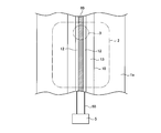
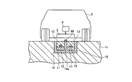
- a pavement structure 1 a is a pavement structure that feeds power to a power receiving device 3 provided in a traveling body 2 through an electromagnetic wave.
- a recess 10 extending in the direction in which the traveling body 2 travels, a magnetic member 11 disposed so that the upper surface is flat inside the recess 10, and an upper surface of the magnetic member 11.
- a power feeding body 12 that feeds power via electromagnetic waves and a power feeding body protection member 13 that covers the power feeding body 12 inside the recess 10 are provided.
- the paved structure 1a is a paved roadway on which the traveling body 2 can travel.
- the pavement structure 1a is paved with, for example, concrete and asphalt.
- the pavement structure 1a has a configuration of a roadbed, a base layer, and a surface layer from the deeper side.
- the pavement structure 1a paved with concrete, asphalt, or the like includes a recess 10, a magnetic member 11, a power supply body 12, and a power supply body protection material 13 in a base layer and a surface layer.
- the recessed part 10 is extended and provided in the direction in which the traveling body 2 travels.
- the recess 10 is formed by cutting with a cutting machine or the like. Inside the recess 10, a magnetic member 11, a power feeding body 12, and a power feeding body protection member 13 are arranged.
- the width of the recesses 10 is preferably 0.3 m to 2.0 m, more preferably 0.5 m to 1.0 m, and the depth of the recess 10 Is preferably 50 mm to 200 mm, more preferably 80 mm to 150 mm.
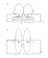
- the magnetic member 11 is disposed on the ground side of the power feeding body 12 so that the upper surface is flat, and functions to control the range of the magnetic field generated by the power feeding body 12.
- Have The magnetic flux in FIG. When the magnetic member 11 is not disposed, as shown in FIG. 3B, the magnetic field generated by the power feeding body 12 is diffused into the ground side of the pavement structure 1a.
- the magnetic flux in FIG.3 (b) is shown with a dotted line.
- the magnetic member 11 having a flat upper surface is disposed, the magnetic flux that diffuses to the ground side of the pavement structure 1 can be concentrated on the surface side of the pavement structure 1a.
- the magnetic member 11 since the magnetic member 11 aggregates magnetic fluxes to form a strong magnetic field, it can also strengthen electromagnetic waves generated by changes in the magnetic field. Furthermore, since the upper surface of the magnetic member 11 is flat, the width of the magnetic flux converging on the surface side is substantially the same as the width of the magnetic member 11, and there is unevenness in the concentration of the magnetic flux in the width direction of the magnetic member 11. Less likely to occur. For this reason, even if the traveling body 2 travels at a position slightly deviated with respect to the recess 10, the power reception of the power receiving device 3 of the traveling body 2 is not significantly affected.
- the magnetic member 11 is made of a magnetic material such as a magnetic slag.
- the magnetic slag is a slag aggregate containing 50 to 80% by mass of a magnetic material such as iron.
- the magnetic member 11 preferably contains 10 to 40% by mass of magnetic substance slag, more preferably 15 to 35% by mass, from the viewpoint of increasing conductivity. Since the magnetic slag is a hard material, from the viewpoint of maintaining the durability of the magnetic member 11 in which the heavy traveling body 2 such as a truck may pass above, the magnetic member 11 includes
- the magnetic material slag is preferably mixed in an amount of 10% by mass or more, more preferably 15% by mass or more. From the viewpoint of having a function of concentrating magnetic flux on the surface side of the pavement structure 1a, the magnetic member 11 preferably has a thickness of 30 mm or more, more preferably 50 mm or more.
- the magnetic member 11 is disposed inside the recess 10 so that the upper surface of the magnetic member 11 is flat. For this reason, since the magnetic body member 11 is disposed inside the recess 10, it is formed in a plate shape.
- the power feeder 12 is arranged in an elliptical coil shape so as to make a circumference. Since the power feeding body 12 is formed in an elliptical coil shape, a semicircular portion and a parallel portion are combined. The parallel portions constitute conductors (electric wires) arranged in parallel so that currents in opposite directions flow.
- a high-frequency current supplied from the power supply facility 5 is supplied to the power supply body 12 through the power supply wiring 50, and the current supply is supplied to the power supply body 12, so that the power supply body 12 generates a magnetic field. .
- an alternating current is passed through the power supply body 12, the magnetic field and the electric field change according to the alternating current frequency to generate an electromagnetic wave.
- the power feeding body protection member 13 is provided so as to cover the power feeding body 12 in order to protect the power feeding body 12 from an impact caused by the traveling body 2 traveling on the pavement structure 1a.
- the power supply body protection member 13 protects the power supply body 12 from external force and prevents physical damage such as interruption or bending of the power supply body 12.
- the power supply protection member 13 preferably has an elastic modulus of 1000 MPa or more, and more preferably 3000 MPa or more.
- the uniaxial compressive strength is preferably 1 MPa or more, and more preferably 3 MPa or more.
- the power supply body protection member 13 preferably has a thickness covering the power supply body 12 of 30 mm or more, and more preferably has a thickness covering the power supply body 12 of 50 mm or more. .
- the traveling body 2 is an electric vehicle (EV), a hybrid vehicle (HEV), or the like, and the power reception device 3 is near the floor of the vehicle body and receives electromagnetic waves irradiated from the power supply body 12.
- the secondary battery 4 is provided below the floor of the passenger compartment, for example, at a possible position.
- the traveling body 2 travels by rotating a motor (not shown) using electric power stored in the secondary battery 4 and driving wheels by the rotational force of the motor.
- the power receiving device 3 is a coil or the like that can extract electric power by an electromagnetic induction phenomenon caused by electromagnetic waves.
- the power receiving device 3 is connected to the secondary battery 4 and transmits the extracted power to the secondary battery 4.
- the power receiving device 3 preferably includes an amplifier that amplifies power.
- the power receiving device 3 receives the electromagnetic wave irradiated from the power feeding body 12 and takes out the electric power generated by the electromagnetic induction phenomenon that occurs when the magnetic flux flows.
- the electric power taken out by the power receiving device 3 is charged into the secondary battery 4 through a control circuit (not shown) that controls charging and discharging.
- the secondary battery 4 includes a control circuit that controls charging and discharging, a cooling device, and the like.
- a chargeable / dischargeable battery such as a lithium ion battery can be used.
- the power supply facility 5 is electrically connected to the power supply body 12 via a power supply wiring 50 disposed in the ground.
- the power supply facility 5 is an AC power supply and supplies a high-frequency current.
- the power supply facility 5 is preferably arranged outside the traveling lane.
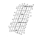
- a plurality of power feeders 12 are fixed or connected to the reinforcing member 40 in order to easily install the power feeders 12 having a constant width and a constant length on site.
- the reinforcing member 40 is, for example, a mesh-like net formed by a plurality of warps 41 and a plurality of wefts 42.
- the reinforcing material 40 is provided on the warps 41 and the wefts 42 and has a plurality of stoppers such as a string for fixing the power supply body 12. Part 43.
- the reinforcing material 40 has substantially the same width as the width of the recess 10.
- the coiled power supply body 12 is disposed at a predetermined position between the warp 41 and the weft 42 and fixed by a stopper 43. Thereby, it can be carried into the construction site in a state where the power supply body 12 having a predetermined shape is attached to the reinforcing member 40 in a place where facilities such as a factory are abundant. For this reason, it is not necessary to wind the power feeding body 12 in a coil shape while measuring at the construction site, and a plurality of power feeding bodies 12 wound uniformly at the construction site can be connected and laid.
- the construction of the pavement structure 1a according to the first embodiment is performed outside the pavement structure 1a such as an expressway.
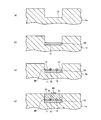
- a recess 10 having a desired width and depth is formed in the pavement structure 1a using a cutting machine or the like.
- the magnetic member 11 is disposed inside the recess 10.
- the magnetic member 11 is formed inside the recess 10 so that the upper surface of the magnetic member 11 is flat. Since the upper surface of the magnetic member 11 is flat, the magnetic member 11 can be easily constructed.
- the reinforcing member 40 with the power feeding body 12 is placed on the magnetic body member 11, and the power feeding body 12 is placed in the recess 10. If integrated wiring of the power feeding body 12 is possible, it is possible to perform laying with good working efficiency by a cable laying car or a winding car.
- the power supply protection member 13 is disposed so as to cover the power supply 12 installed on the magnetic member 11.
- cement asphalt emulsion mortar (CAM) or the like can be used as the power supply protection member 13.
- CAM cement asphalt emulsion mortar
- a dense particle size asphalt mixture or polymer-containing cement concrete may be laid on the surface layer of the pavement structure 1a.
- the traveling body 2 is provided on the pavement structure 1a (road surface) on which the power feeding body 12 is provided by providing a visual recognition unit 60 such as a special pavement that extends in a direction in which the pavement structure 1a extends. The driver is informed of the location where the power feeder 12 is embedded.
- the pavement structure 1a includes the visual recognition unit 60
- the position where the power feeding body 12 is embedded can be easily identified when charging is required.
- the person on the traveling body 2 or the in-vehicle camera mounted on the traveling body 2 can recognize the visual recognition unit 60 provided by the color pavement and control the traveling direction of the traveling body 2.
- the traveling body 2 can be caused to travel so that the power receiving device 3 of the traveling body 2 is accurately positioned above the power feeding body 12 and without meandering with respect to the power feeding body 12.
- the power supply efficiency can be increased.
- the traveling body 2 travels using the electric power stored in the secondary battery 4, as the traveling body 2 travels, the power of the secondary battery 4 is consumed and charging is required.
- the traveling body 2 that needs to be charged travels on the pavement structure 1 a provided with the power feeding body 12.
- the power feeding body 12 When the traveling body 2 is traveling on the pavement structure 1 a provided with the power feeding body 12, the power feeding body 12 is fed with a high-frequency current from the power feeding facility 5 and generates electromagnetic waves generated by the power feeding body 12. Irradiate toward 2. The irradiated electromagnetic wave is received by the power receiving device 3 of the traveling body 2 traveling on the power feeding body 12. The power receiving device 3 takes out electric power from a voltage generated by a change in the electromagnetic wave by using an electromagnetic induction phenomenon generated by the received electromagnetic wave. The power receiving device 3 transmits the extracted power and charges the secondary battery 4.
- the pavement structure 1a According to the pavement structure 1a according to the first embodiment, power can be supplied to the traveling body 2 during traveling via electromagnetic waves. Therefore, since the secondary battery 4 can be charged in the traveling state, even when traveling on a long distance with the traveling body 2 that is an electric vehicle, the traveling is performed without stopping at the charging stand or the like. You can continue.
- the pavement structure 1b according to the second embodiment of the present invention has a concave shape on the inner surface of the recess 10 as compared with the pavement structure 1a shown in the first embodiment. The difference is that an electromagnetic wave shielding member 14 is provided. Since other parts are substantially the same, the description is omitted.
- the electromagnetic wave shielding member 14 is a member that blocks the electromagnetic wave irradiated from the power supply body 12 so as not to propagate as much as possible to the space.
- the electromagnetic wave shielding member 14 preferably has an aggregate formed of stainless steel, aluminum, or a combination thereof, and concrete covering the aggregate.
- the electromagnetic wave shielding member 14 is preferably formed of a stainless steel plate or net, an aluminum plate or net, or a combination thereof.
- a recess 10 having a desired width and depth is formed in the pavement structure 1b using a cutting machine or the like.
- the power feeding body 12 is installed on the magnetic body member 11. If integrated wiring of the power feeding body 12 is possible, it is possible to perform laying with good working efficiency by a cable laying car or a winding car.
- the power supply protection member 13 is disposed so as to cover the power supply 12 installed on the magnetic member 11.
- cement asphalt emulsion mortar (CAM) can be used as the power supply protection member 13.
- CAM cement asphalt emulsion mortar
- a dense particle size asphalt mixture or polymer-containing cement concrete may be laid on the surface layer of the pavement structure 1b.
- the traveling body 2 is provided on the pavement structure 1b on which the power feeding body 12 is provided (road surface) by providing a visual recognition unit 60 such as a special pavement extending in a direction in which the pavement structure 1b extends. The driver is informed of the location where the power feeder 12 is embedded.
- the pavement structure 1b according to the second embodiment of the present invention configured as described above can achieve the same effects as the pavement structure 1a according to the first embodiment.
- the electromagnetic wave shielding member 14 since the electromagnetic wave shielding member 14 is included, it is possible to block electromagnetic waves other than the electromagnetic wave directed to the traveling body 2, and therefore, the power propagates from the power supply body 12 to the space. Electromagnetic waves can be reduced.
- the pavement structure 1c according to the third embodiment of the present invention has two electromagnetic wave shielding members 14 as compared with the pavement structure 1b shown in the second embodiment.
- the difference is that a partition 14a is provided at the center of the recess so that the groove is formed in the recess. Since other parts are substantially the same, the description is omitted.
- the electromagnetic wave shielding member 14 has two grooves, and the power feeder 12 is disposed in each of the two grooves. Since the partition part 14a of the electromagnetic wave shielding member 14 partitions the power feeding bodies 12 disposed in the respective grooves, it is possible to prevent the electromagnetic waves irradiated from the respective power feeding bodies 12 from canceling each other.
- a recess 10 having a desired width and depth is formed in the pavement structure 1b using a cutting machine or the like.
- the power feeder 12 is installed on the magnetic member 11 in which the respective grooves are arranged. If integrated wiring of the power feeding body 12 is possible, it is possible to perform laying with good working efficiency by a cable laying car or a winding car.
- the power supply body protection member 13 is disposed so as to cover the power supply body 12 installed on the magnetic body member 11.
- cement asphalt emulsion mortar CAM
- a dense particle size asphalt mixture or polymer-containing cement concrete may be laid on the surface layer of the pavement structure 1c.
- a visual recognition part 60 that makes it possible to visually recognize the position where the power feeding body 12 is embedded from the traveling body 2 may be provided on the surface of the pavement structure 1 c, particularly on the surface of the partition part 14 a of the electromagnetic wave shielding member 14.
- the power feeding body 12 is embedded in the driver who drives the traveling body 2 by providing the visual recognition section 60, which is a special pavement or the like extending in the direction in which the partition section 14a extends, on the surface of the partition section 14a. Announce whereabouts.
- the pavement structure 1c according to the third embodiment of the present invention configured as described above can achieve the same effects as the pavement structure 1b according to the second embodiment.
- the partition portion 14a of the electromagnetic wave shielding member 14 it is possible to prevent the electromagnetic waves irradiated from the respective power feeding bodies 12 from canceling each other.
- the traveling body 2 can be irradiated with strong electromagnetic waves.
- the visual recognition part 60 is a place where iron oxide (valve, Fe 2 O 3 ) is mixed into the mixture in the fine particle size of the surface layer of the paving structures 1a, 1b, 1c, and paved with a red color mixture.
- the location where the power feeder 12 is embedded is notified by using a color different from that of the other pavement surface.
- the visual recognition part 60 is a location paved with a retroreflective material that performs retroreflection, and may be a location that notifies the driver of the location where the power feeder 12 is embedded by reflection.
Landscapes
- Engineering & Computer Science (AREA)
- Power Engineering (AREA)
- Mechanical Engineering (AREA)
- Transportation (AREA)
- Computer Networks & Wireless Communication (AREA)
- Civil Engineering (AREA)
- Architecture (AREA)
- Structural Engineering (AREA)
- Physics & Mathematics (AREA)
- Electromagnetism (AREA)
- Road Paving Structures (AREA)
- Road Signs Or Road Markings (AREA)
- Charge And Discharge Circuits For Batteries Or The Like (AREA)
- Electric Propulsion And Braking For Vehicles (AREA)
Abstract
Description
[1] 走行体に備えられた受電可能な受電装置に電磁波を介して給電する舗装構造体であって、
前記走行体が走行する方向に延伸する凹部と、
前記凹部の内側に上面が平らになるように配置された磁性体部材と、
前記磁性体部材の上面に設置され、前記受電装置に電磁波を介して給電する給電体と、
前記凹部の内側において、前記給電体を覆う給電体保護材と、を備える、舗装構造体。
[2] 前記凹部の内側に配置可能な所定の幅の補強材を備え、
前記給電体は、前記補強材に取り付けられている、[1]に記載に舗装構造体。
[3] 前記補強材は一定幅及び一定長さを有するメッシュ状のネットであり、
前記給電体がコイル状に前記ネットに取り付けられている、[2]に記載の舗装構造体。
[4] 前記凹部の内側面に凹状に電磁波遮蔽部材が設けられ、前記磁性体部材は、前記電磁波遮蔽部材の凹状の内側に設けられる、[1]又は[2]に記載の舗装構造体。
[5] 前記電磁波遮蔽部材は、2つの溝が凹部の中に形成されるように、凹部の中央に仕切り部を有し、前記給電体は、それぞれ、2つの溝に配置されている、[4]に記載の舗装構造体。
[6] 前記電磁波遮蔽部材は、ステンレス性の板若しくは網、アルミ性の板若しくは網、又はこれらの組み合わせで形成されている、[4]又は[5]に記載の舗装構造体。
[7] 前記給電体保護材は、前記磁性体部材と同じ又は異なる磁性体である、[1]から[6]のいずれかに記載の舗装構造体。
[8] 前記磁性体部材は、磁性体スラグを含んで構成されている、[1]から[7]のいずれかに記載の舗装構造体。
前記視認部は、前記給電体保護材のうち前記給電体の上方の表面に設けられている、[1]から[8]のいずれかに記載の舗装構造体。
[10] 前記視認部は、前記給電体保護材の色とは異なる色で着色されている、[9]に記載の舗装構造体。
[11] 前記視認部は、再帰反射をする再帰反射素材で構成されている、[9]又は[10]に記載の舗装構造体。
[12] [1]から[11]に記載の舗装構造体の施工方法であって、
舗装構造体に凹部を形成する凹部形成工程と、
前記凹部の内側に前記磁性体部材を配置する磁性体配置工程と、
前記磁性体部材上に前記給電体を設置する給電体設置工程と、を含む、舗装構造体の施工方法。
図1に示すように、本発明の第1の実施の形態に係る舗装構造体1aは、走行体2に備えられた受電可能な受電装置3に電磁波を介して給電する舗装構造体であって、走行体2が走行する方向に延伸する凹部10と、凹部10の内側に上面が平らになるように配置された磁性体部材11と、磁性体部材11の上面に設置され、受電装置3に電磁波を介して給電する給電体12と、凹部10の内側において、給電体12を覆う給電体保護材13とを備える。
さらに、磁性体部材11の上面が平らなので、表面側に収束する磁束の幅は、磁性体部材11の幅と概ね同じになり、また、磁性体部材11の幅方向における磁束の集約のムラがそれほど生じにくくなる。このため、走行体2が、凹部10に対して若干ずれた位置を走行しても、走行体2の受電装置3の受電にはそれほど影響しない。
磁性体部材11は、舗装構造体1aの表面側に磁束を集約させる機能を有する観点から、厚さが30mm以上であることが好ましく、より好ましくは厚さが50mm以上である。
図2に示すように、給電体12には、給電配線50を介して給電設備5から供給される高周波電流が通電され、給電体12に電流が通電することにより給電体12は磁界を生成する。給電体12に、交流電流を流すと、交流の周波数に従って磁界及び電界が変化し、電磁波を発生する。
図4に示すように、一定幅、一定長さを保持した給電体12を現場で簡易に設置するために、補強材40に複数の給電体12を固定又は連結する。
補強材40は、例えば、複数の経糸41と複数の緯糸42とによって形成されたメッシュ状のネットであり、経糸41及び緯糸42に設けられ、給電体12を固定するひものような複数の止め部43を有する。補強材40は、凹部10の幅と略同じ幅を有する。
経糸41及び緯糸42とで形成する矩形の大きさは、互いに同じであることが好ましい。
補強材40は、コイル状にされた給電体12を、経糸41と緯糸42との所定の位置に配置し、止め部43で固定する。
これにより、工場など設備が豊富にある場所で、予め、所定形状にした給電体12を補強材40に取り付けた状態で、工事現場に搬入することができる。このため、工事現場で採寸しながら給電体12をコイル状に巻くことを不要とすることができ、工事現場で均一に巻かれた複数の給電体12を連結させかつ敷設することができる。
まず、図5(a)に示す工程において、切削機などを用いて所望の幅及び深さの凹部10を舗装構造体1aに形成する。
次に、図5(b)に示す工程において、凹部10の内側に磁性体部材11を配置する。磁性体部材11の上面が平らになるように、磁性体部材11を凹部10の内側に形成する。磁性体部材11の上面が平らなので、磁性体部材11の施工を容易に行うことができる。
次に、図5(c)に示す工程において、磁性体部材11に給電体12付き補強材40を置き、給電体12を凹部10内に設置する。給電体12の一体型の配線が可能であれば、ケーブル敷設車や巻取り車による作業効率が好適な敷設をすることができる。
次に、図5(d)に示す工程において、磁性体部材11に設置された給電体12を覆うように給電体保護材13を配置する。給電体保護材13としては、例えば、セメントアスファルト乳剤モルタル(CAM)などを用いることができる。
更に、舗装構造体1aの表層に、密粒度アスファルト混合物又はポリマー入りセメントコンクリートを敷設してもよい。
更に、舗装構造体1aの表層に、給電体12が埋設されている位置を走行体2から視認可能とする視認部60を設けてもよい。具体的には、給電体12が設けられている舗装構造体1a上(路面)に、舗装構造体1aが伸びる方向に伸びる特別な舗装などである視認部60を設けることで、走行体2を運転する運転手に給電体12が埋設されている所在を報知する。
これにより、走行体2に乗車している人間又は走行体2に搭載された車載カメラが、カラー舗装で設けられた視認部60を認識し、走行体2の走行方向を制御することができる。このため、走行体2の受電装置3が給電体12の上方に精度よく位置するように、かつ、給電体12に対して蛇行させることなく、走行体2を走行させることができ、受電装置3の給電効率を上昇させることができる。
走行体2は、二次電池4に蓄えられた電力を利用して走行するので、走行するに従い、二次電池4の電力が消費されて充電が必要になる。充電が必要になった走行体2は、給電体12が設けられている舗装構造体1aを走行する。
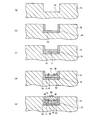
本発明の第2の実施の形態に係る舗装構造体1bは、図6に示すように、第1の実施の形態で示した舗装構造体1aと比して、凹部10の内側面に凹状に電磁波遮蔽部材14が設けられている点が異なる。その他については実質的に同様であるので記載を省略する。
電磁波遮蔽部材14は、ステンレス、アルミ又はこれらの組み合わせで形成した骨材と骨材を覆うコンクリートとを有することが好ましい。
又は、電磁波遮蔽部材14は、ステンレス性の板若しくは網、アルミ性の板若しくは網、又はこれらの組み合わせで形成されていることが好ましい。
まず、図7(a)に示す工程において、切削機などを用いて所望の幅及び深さの凹部10を舗装構造体1bに形成する。
次に、図7(b)に示す工程において、凹部10の内側面に接するように凹状の電磁波遮蔽部材14を配置する。
次に、図7(c)に示す工程において、電磁波遮蔽部材14の内側に磁性体部材11を配置する。
次に、図7(d)に示す工程において、磁性体部材11に給電体12を設置する。給電体12の一体型の配線が可能であれば、ケーブル敷設車や巻取り車による作業効率が好適な敷設をすることができる。
次に、図7(e)に示す工程において、磁性体部材11に設置された給電体12を覆うように給電体保護材13を配置する。給電体保護材13としては、例えば、セメントアスファルト乳剤モルタル(CAM)を用いることができる。
更に、舗装構造体1bの表層に、密粒度アスファルト混合物又はポリマー入りセメントコンクリートを敷設してもよい。
更に、舗装構造体1bの表層に、給電体12が埋設されている位置を走行体2から視認可能とする視認部60を設けてもよい。具体的には、給電体12が設けられている舗装構造体1b上(路面)に、舗装構造体1bが伸びる方向に伸びる特別な舗装などである視認部60を設けることで、走行体2を運転する運転手に給電体12が埋設されている所在を報知する。
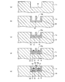
本発明の第3の実施の形態に係る舗装構造体1cは、図8に示すように、第2の実施の形態で示した舗装構造体1bと比して、電磁波遮蔽部材14は、2つの溝が凹部の中に形成されるように、凹部の中央に仕切り部14aを有する点が異なる。その他については実質的に同様であるので記載を省略する。
電磁波遮蔽部材14の仕切り部14aは、それぞれの溝に配置された給電体12を仕切っているので、それぞれの給電体12から照射される電磁波が打ち消しあってしまうのを防ぐことができる。
まず、図9(a)に示す工程において、切削機などを用いて所望の幅及び深さの凹部10を舗装構造体1bに形成する。
次に、図9(b)に示す工程において、凹部10の内側面に接するように、仕切り部14aによって2つの溝が形成された電磁波遮蔽部材14を配置する。
次に、図9(c)に示す工程において、電磁波遮蔽部材14の2つの溝のそれぞれの内側に磁性体部材11を配置する。
次に、図9(d)に示す工程において、それぞれの溝の配置された磁性体部材11に給電体12を設置する。給電体12の一体型の配線が可能であれば、ケーブル敷設車や巻取り車による作業効率が好適な敷設をすることができる。
次に、図9(e)に示す工程において、磁性体部材11に設置された給電体12を覆うように給電体保護材13を配置する。給電体保護材13としては、例えば、セメントアスファルト乳剤モルタル(CAM)を用いることができる。
更に、舗装構造体1cの表層に、密粒度アスファルト混合物又はポリマー入りセメントコンクリートを敷設してもよい。
更に、舗装構造体1cの表層、特に、電磁波遮蔽部材14の仕切り部14aの表面に、給電体12が埋設されている位置を走行体2から視認可能とする視認部60を設けてもよい。具体的には、仕切り部14aが伸びる方向に伸びる特別な舗装などである視認部60を仕切り部14aの表面に設けることで、走行体2を運転する運転手に給電体12が埋設されている所在を報知する。
上記のように、本発明は実施の形態によって記載したが、この開示の一部をなす記述及び図面はこの発明を限定するものであると理解するべきではない。この開示から当業者には様々な代替実施の形態、実施例及び運用技術が明らかになるはずである。
2…走行体
3…受電装置
4…二次電池
5…給電設備
10…凹部
11…磁性体部材
12…給電体
13…給電体保護材
14…電磁波遮蔽部材
40…補強材
50…給電配線
60…視認部
Claims (12)
- 走行体に備えられた受電可能な受電装置に電磁波を介して給電する舗装構造体であって、
前記走行体が走行する方向に延伸する凹部と、
前記凹部の内側に平らな上面が形成されるように配置された磁性体部材と、
前記磁性体部材の上面に設置され、前記受電装置に電磁波を介して給電する給電体と、
前記凹部の内側において、前記給電体を覆う給電体保護材と、を備える、舗装構造体。 - 前記凹部の内側に配置可能な所定の幅の補強材を備え、
前記給電体は、前記補強材に取り付けられている、請求項1に記載に舗装構造体。 - 前記補強材は一定幅及び一定長さを有するメッシュ状のネットであり、
前記給電体がコイル状に前記ネットに取り付けられている、請求項2に記載の舗装構造体。 - 前記凹部の内側面に凹状に電磁波遮蔽部材が設けられ、前記磁性体部材は、前記電磁波遮蔽部材の凹状の内側に設けられる、請求項1又は2に記載の舗装構造体。
- 前記電磁波遮蔽部材は、2つの溝が凹部の中に形成されるように、凹部の中央に仕切り部を有し、前記給電体は、それぞれ、2つの溝に配置されている、請求項4に記載の舗装構造体。
- 前記電磁波遮蔽部材は、ステンレス性の板若しくは網、アルミ性の板若しくは網、又はこれらの組み合わせで形成されている、請求項4又は5に記載の舗装構造体。
- 前記給電体保護材は、前記磁性体部材と同じ又は異なる磁性体である、請求項1から6のいずれかに記載の舗装構造体。
- 前記磁性体部材は、磁性体スラグを含んで構成されている、請求項1から7のいずれかに記載の舗装構造体。
- 前記走行体から視認可能な視認部を備え、
前記視認部は、前記給電体保護材のうち前記給電体の上方の表面に設けられている、請求項1から8のいずれかに記載の舗装構造体。 - 前記視認部は、前記給電体保護材の色とは異なる色で着色されている、請求項9に記載の舗装構造体。
- 前記視認部は、再帰反射をする再帰反射素材で構成されている、請求項9又は10に記載の舗装構造体。
- 請求項1から11に記載の舗装構造体の施工方法であって、
舗装構造体に凹部を形成する凹部形成工程と、
前記凹部の内側に前記磁性体部材を配置する磁性体配置工程と、
前記磁性体部材上に前記給電体を設置する給電体設置工程と、を含む、舗装構造体の施工方法。
Priority Applications (4)
| Application Number | Priority Date | Filing Date | Title |
|---|---|---|---|
| CN201380074841.0A CN105189869B (zh) | 2013-03-21 | 2013-08-28 | 铺装结构体以及铺装结构体的施工方法 |
| EP13878844.3A EP3000934A4 (en) | 2013-03-21 | 2013-08-28 | PADDED STRUCTURE AND CONSTRUCTION PROCESSES FOR PAVED STRUCTURE |
| US14/778,285 US9873333B2 (en) | 2013-03-21 | 2013-08-28 | Paved structure and construction method for paved structure |
| KR1020157025755A KR101790422B1 (ko) | 2013-03-21 | 2013-08-28 | 포장 구조체 및 포장 구조체의 시공 방법 |
Applications Claiming Priority (2)
| Application Number | Priority Date | Filing Date | Title |
|---|---|---|---|
| JP2013058497A JP5374657B1 (ja) | 2013-03-21 | 2013-03-21 | 舗装構造体及び舗装構造体の施工方法 |
| JP2013-058497 | 2013-03-21 |
Publications (1)
| Publication Number | Publication Date |
|---|---|
| WO2014147860A1 true WO2014147860A1 (ja) | 2014-09-25 |
Family
ID=49954970
Family Applications (1)
| Application Number | Title | Priority Date | Filing Date |
|---|---|---|---|
| PCT/JP2013/073062 WO2014147860A1 (ja) | 2013-03-21 | 2013-08-28 | 舗装構造体及び舗装構造体の施工方法 |
Country Status (6)
| Country | Link |
|---|---|
| US (1) | US9873333B2 (ja) |
| EP (1) | EP3000934A4 (ja) |
| JP (1) | JP5374657B1 (ja) |
| KR (1) | KR101790422B1 (ja) |
| CN (1) | CN105189869B (ja) |
| WO (1) | WO2014147860A1 (ja) |
Cited By (1)
| Publication number | Priority date | Publication date | Assignee | Title |
|---|---|---|---|---|
| US10763024B2 (en) | 2016-10-03 | 2020-09-01 | Kabushiki Kaisha Toshiba | Power transmission apparatus |
Families Citing this family (16)
| Publication number | Priority date | Publication date | Assignee | Title |
|---|---|---|---|---|
| JP6457767B2 (ja) * | 2014-09-19 | 2019-01-23 | 大成建設株式会社 | 給電導体の埋設構造 |
| US10059213B2 (en) | 2015-11-13 | 2018-08-28 | Nio Usa, Inc. | Charging devices within wheel portions |
| US10124690B2 (en) | 2015-11-13 | 2018-11-13 | Nio Usa, Inc. | Electric vehicle charging device positioning and method of use |
| US10093195B2 (en) | 2015-11-13 | 2018-10-09 | Nio Usa, Inc. | Integrated vehicle charging panel system and method of use |
| US10336194B2 (en) * | 2015-11-13 | 2019-07-02 | Nio Usa, Inc. | Electric vehicle charging device alignment and method of use |
| JP6647625B2 (ja) * | 2016-03-11 | 2020-02-14 | 大成建設株式会社 | 給電導体の埋設構造及び非接触型給電走行路 |
| JP6810932B2 (ja) * | 2016-10-17 | 2021-01-13 | 大成建設株式会社 | 給電電極の埋設構造及び非接触型給電走行路 |
| CN106592371A (zh) * | 2016-12-16 | 2017-04-26 | 武汉理工大学 | 一种可供车辆行驶中充电的沥青路面 |
| TWI678047B (zh) * | 2017-10-20 | 2019-11-21 | 鴻海精密工業股份有限公司 | 一種無線充電汽車及無線充電馬路 |
| JP7087664B2 (ja) * | 2018-05-17 | 2022-06-21 | 株式会社Ihi | コイル装置 |
| CN108944497A (zh) * | 2018-05-30 | 2018-12-07 | 合肥市春华起重机械有限公司 | 一种agv小车无线充电系统 |
| IT201800006495A1 (it) * | 2018-06-20 | 2019-12-20 | Procedimento per l’installazione diretta su strada di induttori per trasferimento induttivo di potenza elettrica | |
| CN116657536A (zh) * | 2018-09-30 | 2023-08-29 | 王奎 | 城区净尘系统及应用和城区净尘方法 |
| JP7331394B2 (ja) * | 2019-03-15 | 2023-08-23 | 株式会社デンソー | 走行中給電システム |
| DE102020212391A1 (de) * | 2020-09-30 | 2022-03-31 | Mahle International Gmbh | Fahrbahn-Deckenplatte für eine induktive Baugruppe |
| EP4056413A1 (de) * | 2021-03-11 | 2022-09-14 | STILL GmbH | Batterieladevorrichtung für induktives laden, insbesondere dynamisches und/oder stationäres induktives laden, einer traktionsbatterie eines fahrzeugs |
Citations (7)
| Publication number | Priority date | Publication date | Assignee | Title |
|---|---|---|---|---|
| JPH01238638A (ja) | 1988-03-19 | 1989-09-22 | Fuji Photo Film Co Ltd | 放射線照射野輪郭候補点検出方法 |
| JPH0678406A (ja) * | 1992-08-28 | 1994-03-18 | Daifuku Co Ltd | 移動体の無接触給電設備 |
| JP2000116036A (ja) * | 1998-09-29 | 2000-04-21 | Yamaha Motor Co Ltd | 輸送設備 |
| JP2007012775A (ja) * | 2005-06-29 | 2007-01-18 | Daido Steel Co Ltd | 電磁波吸収材 |
| JP2010022183A (ja) * | 2008-02-08 | 2010-01-28 | Suri-Ai:Kk | 電気自動車及びそれに好適な車両用誘導送電装置 |
| JP2010172084A (ja) | 2009-01-21 | 2010-08-05 | Saitama Univ | 非接触給電装置 |
| JP2011049230A (ja) | 2009-08-25 | 2011-03-10 | Saitama Univ | 非接触給電装置 |
Family Cites Families (33)
| Publication number | Priority date | Publication date | Assignee | Title |
|---|---|---|---|---|
| US4361202A (en) * | 1979-06-15 | 1982-11-30 | Michael Minovitch | Automated road transportation system |
| US5390118A (en) * | 1990-10-03 | 1995-02-14 | Aisin Seiki Kabushiki Kaisha | Automatic lateral guidance control system |
| DE69111992T2 (de) * | 1990-11-29 | 1996-01-11 | Mitsubishi Kagaku Sanshi Corp | Verfahren zum Herstellen von bituminösen Strassen mit darunter verlegten Heizungrohren. |
| JPH0767205A (ja) * | 1993-08-25 | 1995-03-10 | Sumitomo Electric Ind Ltd | 移動体の非接触給電装置における1次コイルと2次コイル |
| US5573090A (en) | 1994-05-05 | 1996-11-12 | H. R. Ross Industries, Inc. | Raodway-powered electric vehicle system having onboard power metering and communication channel features |
| US5595271A (en) | 1995-08-07 | 1997-01-21 | Tseng; Ling-Yuan | Electric vehicle pick-up position control |
| JPH11238638A (ja) | 1998-02-23 | 1999-08-31 | Toyota Autom Loom Works Ltd | 非接触型充電装置 |
| CN1463868A (zh) | 2002-06-14 | 2003-12-31 | 李善伯 | 电动汽车地槽输电与运行状态信息采集方法 |
| JP2005224045A (ja) * | 2004-02-06 | 2005-08-18 | Mitsubishi Heavy Ind Ltd | 非接触給電装置および非接触給電装置を備えた架線レスシステム |
| KR100884188B1 (ko) | 2005-07-01 | 2009-02-17 | 옥은호 | 지중 전기공급 레일 도로와 집전장치를 갖춘 전기자동차 |
| JP4209437B2 (ja) | 2006-11-10 | 2009-01-14 | 三菱重工業株式会社 | 移動体の非接触給電装置及びその保護装置 |
| DE102008013649B4 (de) | 2008-03-11 | 2010-04-15 | Sew-Eurodrive Gmbh & Co. Kg | Vorrichtung zur berührungslosen Energieübertragung und Verwendung der Vorrichtung |
| KR100944113B1 (ko) * | 2009-02-27 | 2010-02-24 | 한국과학기술원 | 전기자동차용 전원공급 시스템 및 방법 |
| US8221024B2 (en) | 2009-09-03 | 2012-07-17 | General Atomics | Embedded module for linear synchronous motor |
| KR101104813B1 (ko) | 2009-10-16 | 2012-01-17 | 한국과학기술원 | 콘크리트 구조물에 의해 보호되는 전기자동차용 급전장치 |
| WO2011046414A2 (en) | 2009-10-16 | 2011-04-21 | Korea Advanced Institute Of Science And Technology | Power supply apparatus for on-line electric vehicle, method for forming same and magnetic field cancelation apparatus |
| US20110094840A1 (en) | 2009-10-26 | 2011-04-28 | Masami Sakita | Electric highway system |
| JP5641891B2 (ja) * | 2009-11-13 | 2014-12-17 | パナソニック株式会社 | 車両用充給電システム |
| EP2515314B1 (en) | 2009-12-17 | 2019-05-15 | Toyota Jidosha Kabushiki Kaisha | Non-contact power reception device and corresponding transmission device |
| GB2476318A (en) * | 2009-12-21 | 2011-06-22 | Bombardier Transp Gmbh | Laying electrical conductors along a track for a vehicle |
| KR101038759B1 (ko) | 2009-12-21 | 2011-06-03 | 한국과학기술원 | Emf 능동차폐 기능을 포함하는 온라인 전기자동차용 집전장치 |
| KR20110074350A (ko) * | 2009-12-24 | 2011-06-30 | 한국과학기술원 | 온라인 전기자동차용 듀얼레일 급전 시스템의 전자기장 차폐장치 및 방법 |
| KR20120104615A (ko) | 2009-12-24 | 2012-09-21 | 러스크 인텔렉츄얼 리저브 아게 | 전기 차량 및 그의 급전 장치 |
| KR101232036B1 (ko) | 2010-10-13 | 2013-02-12 | 한국과학기술원 | 비접촉 전력전달 장치 및 자기유도 방식의 급전장치 |
| CN201915316U (zh) * | 2010-11-20 | 2011-08-03 | 孙善骏 | 移动电磁充电站道路 |
| CN102465482A (zh) | 2010-11-20 | 2012-05-23 | 孙善骏 | 移动电磁充电站道路 |
| GB2485616A (en) | 2010-11-22 | 2012-05-23 | Bombardier Transp Gmbh | Route for transferring electric energy to vehicles |
| GB2485617A (en) | 2010-11-22 | 2012-05-23 | Bombardier Transp Gmbh | Conductor arrangement for inductively transferring electric energy to a vehicle |
| CN201966647U (zh) * | 2011-01-29 | 2011-09-07 | 孙善骏 | 移动电磁充电电动汽车充电装置 |
| JP5777139B2 (ja) * | 2011-02-23 | 2015-09-09 | 株式会社豊田中央研究所 | 車両給電装置及び車両給電方法 |
| WO2012141357A1 (ko) | 2011-04-15 | 2012-10-18 | 한국과학기술원 | 비접촉 자기유도 충전방식의 급전레일모듈 및 이를 적용한 도로구조, 그리고 도로 시공방법 |
| JP2012248747A (ja) * | 2011-05-30 | 2012-12-13 | Toyota Industries Corp | 共鳴型非接触給電システムのシールド装置 |
| EP2737606B1 (en) | 2011-07-26 | 2019-01-16 | LG Innotek Co., Ltd. | Wireless power transmitter and wireless power receiver |
-
2013
- 2013-03-21 JP JP2013058497A patent/JP5374657B1/ja active Active
- 2013-08-28 WO PCT/JP2013/073062 patent/WO2014147860A1/ja active Application Filing
- 2013-08-28 CN CN201380074841.0A patent/CN105189869B/zh not_active Expired - Fee Related
- 2013-08-28 KR KR1020157025755A patent/KR101790422B1/ko active IP Right Grant
- 2013-08-28 US US14/778,285 patent/US9873333B2/en active Active
- 2013-08-28 EP EP13878844.3A patent/EP3000934A4/en not_active Withdrawn
Patent Citations (7)
| Publication number | Priority date | Publication date | Assignee | Title |
|---|---|---|---|---|
| JPH01238638A (ja) | 1988-03-19 | 1989-09-22 | Fuji Photo Film Co Ltd | 放射線照射野輪郭候補点検出方法 |
| JPH0678406A (ja) * | 1992-08-28 | 1994-03-18 | Daifuku Co Ltd | 移動体の無接触給電設備 |
| JP2000116036A (ja) * | 1998-09-29 | 2000-04-21 | Yamaha Motor Co Ltd | 輸送設備 |
| JP2007012775A (ja) * | 2005-06-29 | 2007-01-18 | Daido Steel Co Ltd | 電磁波吸収材 |
| JP2010022183A (ja) * | 2008-02-08 | 2010-01-28 | Suri-Ai:Kk | 電気自動車及びそれに好適な車両用誘導送電装置 |
| JP2010172084A (ja) | 2009-01-21 | 2010-08-05 | Saitama Univ | 非接触給電装置 |
| JP2011049230A (ja) | 2009-08-25 | 2011-03-10 | Saitama Univ | 非接触給電装置 |
Non-Patent Citations (1)
| Title |
|---|
| See also references of EP3000934A4 |
Cited By (1)
| Publication number | Priority date | Publication date | Assignee | Title |
|---|---|---|---|---|
| US10763024B2 (en) | 2016-10-03 | 2020-09-01 | Kabushiki Kaisha Toshiba | Power transmission apparatus |
Also Published As
| Publication number | Publication date |
|---|---|
| EP3000934A4 (en) | 2016-11-02 |
| US20160229294A1 (en) | 2016-08-11 |
| CN105189869A (zh) | 2015-12-23 |
| CN105189869B (zh) | 2018-05-18 |
| US9873333B2 (en) | 2018-01-23 |
| JP5374657B1 (ja) | 2013-12-25 |
| EP3000934A1 (en) | 2016-03-30 |
| KR20150135276A (ko) | 2015-12-02 |
| KR101790422B1 (ko) | 2017-10-25 |
| JP2014181546A (ja) | 2014-09-29 |
Similar Documents
| Publication | Publication Date | Title |
|---|---|---|
| JP5374657B1 (ja) | 舗装構造体及び舗装構造体の施工方法 | |
| JP6149101B2 (ja) | トラフ、舗装構造体、及び舗装構造体の施工方法 | |
| US8807308B2 (en) | Power supply device, power acquisition device and safety system for electromagnetic induction-powered electric vehicle | |
| JP4691000B2 (ja) | 移動体の非接触給電装置 | |
| US8833533B2 (en) | Ultra slim power supply device and power acquisition device for electric vehicle | |
| US8997955B2 (en) | Transferring electric energy to a vehicle by induction | |
| KR20120123280A (ko) | 선로계 차량용 선로 | |
| CN103687745B (zh) | 预制导体构造及其制造方法、道路结构及其建造方法 | |
| EP2375533A2 (en) | Mobile type non-contact power feeding device | |
| KR20160146849A (ko) | 유도성 전력 전달 시스템에서 이질적인 물체들을 검출하기 위한 물체 검출 시스템 및 방법 | |
| WO2013061610A1 (ja) | 給電装置、受電装置、及び非接触充電装置 | |
| JP6457767B2 (ja) | 給電導体の埋設構造 | |
| JP2018065407A (ja) | 給電電極の埋設構造及び非接触型給電走行路 | |
| CN104507740A (zh) | 用于支撑产生电磁场的导体结构的缆线支撑,导体结构,和用于包括该导体结构的车辆的路线 |
Legal Events
| Date | Code | Title | Description |
|---|---|---|---|
| WWE | Wipo information: entry into national phase |
Ref document number: 201380074841.0 Country of ref document: CN |
|
| 121 | Ep: the epo has been informed by wipo that ep was designated in this application |
Ref document number: 13878844 Country of ref document: EP Kind code of ref document: A1 |
|
| WWE | Wipo information: entry into national phase |
Ref document number: 2013878844 Country of ref document: EP |
|
| ENP | Entry into the national phase |
Ref document number: 20157025755 Country of ref document: KR Kind code of ref document: A |
|
| WWE | Wipo information: entry into national phase |
Ref document number: 14778285 Country of ref document: US |
|
| NENP | Non-entry into the national phase |
Ref country code: DE |