WO2014141487A1 - Appareil de source d'alimentation sans coupure - Google Patents
Appareil de source d'alimentation sans coupure Download PDFInfo
- Publication number
- WO2014141487A1 WO2014141487A1 PCT/JP2013/057566 JP2013057566W WO2014141487A1 WO 2014141487 A1 WO2014141487 A1 WO 2014141487A1 JP 2013057566 W JP2013057566 W JP 2013057566W WO 2014141487 A1 WO2014141487 A1 WO 2014141487A1
- Authority
- WO
- WIPO (PCT)
- Prior art keywords
- power
- power supply
- battery
- unit
- supply unit
- Prior art date
Links
Images


Classifications
-
- H—ELECTRICITY
- H02—GENERATION; CONVERSION OR DISTRIBUTION OF ELECTRIC POWER
- H02J—CIRCUIT ARRANGEMENTS OR SYSTEMS FOR SUPPLYING OR DISTRIBUTING ELECTRIC POWER; SYSTEMS FOR STORING ELECTRIC ENERGY
- H02J1/00—Circuit arrangements for dc mains or dc distribution networks
- H02J1/08—Three-wire systems; Systems having more than three wires
-
- G—PHYSICS
- G06—COMPUTING; CALCULATING OR COUNTING
- G06F—ELECTRIC DIGITAL DATA PROCESSING
- G06F1/00—Details not covered by groups G06F3/00 - G06F13/00 and G06F21/00
-
- G—PHYSICS
- G06—COMPUTING; CALCULATING OR COUNTING
- G06F—ELECTRIC DIGITAL DATA PROCESSING
- G06F1/00—Details not covered by groups G06F3/00 - G06F13/00 and G06F21/00
- G06F1/26—Power supply means, e.g. regulation thereof
- G06F1/263—Arrangements for using multiple switchable power supplies, e.g. battery and AC
-
- H—ELECTRICITY
- H02—GENERATION; CONVERSION OR DISTRIBUTION OF ELECTRIC POWER
- H02J—CIRCUIT ARRANGEMENTS OR SYSTEMS FOR SUPPLYING OR DISTRIBUTING ELECTRIC POWER; SYSTEMS FOR STORING ELECTRIC ENERGY
- H02J1/00—Circuit arrangements for dc mains or dc distribution networks
- H02J1/10—Parallel operation of dc sources
- H02J1/102—Parallel operation of dc sources being switching converters
-
- H—ELECTRICITY
- H02—GENERATION; CONVERSION OR DISTRIBUTION OF ELECTRIC POWER
- H02J—CIRCUIT ARRANGEMENTS OR SYSTEMS FOR SUPPLYING OR DISTRIBUTING ELECTRIC POWER; SYSTEMS FOR STORING ELECTRIC ENERGY
- H02J7/00—Circuit arrangements for charging or depolarising batteries or for supplying loads from batteries
- H02J7/34—Parallel operation in networks using both storage and other dc sources, e.g. providing buffering
- H02J7/35—Parallel operation in networks using both storage and other dc sources, e.g. providing buffering with light sensitive cells
-
- H—ELECTRICITY
- H02—GENERATION; CONVERSION OR DISTRIBUTION OF ELECTRIC POWER
- H02J—CIRCUIT ARRANGEMENTS OR SYSTEMS FOR SUPPLYING OR DISTRIBUTING ELECTRIC POWER; SYSTEMS FOR STORING ELECTRIC ENERGY
- H02J9/00—Circuit arrangements for emergency or stand-by power supply, e.g. for emergency lighting
- H02J9/04—Circuit arrangements for emergency or stand-by power supply, e.g. for emergency lighting in which the distribution system is disconnected from the normal source and connected to a standby source
- H02J9/06—Circuit arrangements for emergency or stand-by power supply, e.g. for emergency lighting in which the distribution system is disconnected from the normal source and connected to a standby source with automatic change-over, e.g. UPS systems
- H02J9/062—Circuit arrangements for emergency or stand-by power supply, e.g. for emergency lighting in which the distribution system is disconnected from the normal source and connected to a standby source with automatic change-over, e.g. UPS systems for AC powered loads
-
- H—ELECTRICITY
- H02—GENERATION; CONVERSION OR DISTRIBUTION OF ELECTRIC POWER
- H02J—CIRCUIT ARRANGEMENTS OR SYSTEMS FOR SUPPLYING OR DISTRIBUTING ELECTRIC POWER; SYSTEMS FOR STORING ELECTRIC ENERGY
- H02J2300/00—Systems for supplying or distributing electric power characterised by decentralized, dispersed, or local generation
- H02J2300/20—The dispersed energy generation being of renewable origin
- H02J2300/28—The renewable source being wind energy
-
- Y—GENERAL TAGGING OF NEW TECHNOLOGICAL DEVELOPMENTS; GENERAL TAGGING OF CROSS-SECTIONAL TECHNOLOGIES SPANNING OVER SEVERAL SECTIONS OF THE IPC; TECHNICAL SUBJECTS COVERED BY FORMER USPC CROSS-REFERENCE ART COLLECTIONS [XRACs] AND DIGESTS
- Y02—TECHNOLOGIES OR APPLICATIONS FOR MITIGATION OR ADAPTATION AGAINST CLIMATE CHANGE
- Y02B—CLIMATE CHANGE MITIGATION TECHNOLOGIES RELATED TO BUILDINGS, e.g. HOUSING, HOUSE APPLIANCES OR RELATED END-USER APPLICATIONS
- Y02B10/00—Integration of renewable energy sources in buildings
- Y02B10/70—Hybrid systems, e.g. uninterruptible or back-up power supplies integrating renewable energies
-
- Y—GENERAL TAGGING OF NEW TECHNOLOGICAL DEVELOPMENTS; GENERAL TAGGING OF CROSS-SECTIONAL TECHNOLOGIES SPANNING OVER SEVERAL SECTIONS OF THE IPC; TECHNICAL SUBJECTS COVERED BY FORMER USPC CROSS-REFERENCE ART COLLECTIONS [XRACs] AND DIGESTS
- Y02—TECHNOLOGIES OR APPLICATIONS FOR MITIGATION OR ADAPTATION AGAINST CLIMATE CHANGE
- Y02E—REDUCTION OF GREENHOUSE GAS [GHG] EMISSIONS, RELATED TO ENERGY GENERATION, TRANSMISSION OR DISTRIBUTION
- Y02E10/00—Energy generation through renewable energy sources
- Y02E10/70—Wind energy
- Y02E10/76—Power conversion electric or electronic aspects
Definitions
- the present invention relates to an uninterruptible power supply apparatus that can efficiently supply power to the load device in accordance with the power requirement amount of the load device and the supply status of AC power to save power.
- FIG. 6 is a schematic configuration diagram of a conventional general power supply system in a data center including a plurality of load devices using a DC voltage as a driving power source, for example, a plurality of servers.
- This power supply system includes an uninterruptible power supply (UPS) 1 interposed in a 400V system power supply and high-voltage AC power (AC400V) fed via the uninterruptible power supply 1, for example, 200V or And an AC power supply distributor (PDU) 2 for converting into 100V AC power.
- UPS uninterruptible power supply
- AC400V high-voltage AC power
- PDU AC power supply distributor
- the uninterruptible power supply 1 basically includes a large capacity battery (BAT) 1a capable of storing DC power.
- the uninterruptible power supply 1 includes an AC / DC converter 1b that converts the high-voltage AC power into a DC voltage to charge the battery 1a, an output voltage of the AC / DC converter 1b, or the battery 1a. And a DC / AC converter 1c that converts the DC power stored in the battery into high-voltage AC power and outputs it.
- the power distribution unit 2 includes a circuit breaker 2a that separates, for example, the system power supply and the load facility side including the load device (server).
- the AC power supply distributor 2 further includes a transformer 2b that converts the high-voltage AC power (AC 400V) into, for example, 200V AC power and outputs it.
- reference numeral 3 denotes a transformer that converts AC power distributed at, for example, 6.6 kV into the high-voltage AC power (AC 400 V) and draws it into a building in which the uninterruptible power supply 1 and the like are provided.
- the load equipment constructed by including a plurality of servers 4 as the load devices is connected to the power supply distributor 2 at the front stage thereof, and is the drive power supply voltage of the server 4 from the AC power (AC200V).
- a switching power supply 5 that generates low-voltage direct current power (for example, DC12V) of 48V or less is provided.
- the switching power supply 5 generally includes an AC / DC converter 5a that converts the AC power (AC 200V) into a DC voltage, and a DC output voltage that supplies the output voltage of the AC / DC converter 5a to the server 4. And a DC / DC converter 5b for conversion to (DC12V).
- the plurality of servers 4 are respectively connected to the switching power supply 5 and are operated by being supplied with the DC output voltage, which is a driving power supply for the server 4, from the switching power supply 5 (see, for example, Patent Document 1).
- the plurality of servers 4 are generally installed in a server rack by a predetermined number of servers 4 to form a server group, and the switching power supply 5 is provided corresponding to each server group.
- the switching power supply 5 is housed in the server rack together with the predetermined number of servers 4.
- Patent Document 2 discloses that the uninterruptible power supply is operated in parallel.
- Patent Document 3 discloses that when the number of parallel operations of the uninterruptible power supply apparatus is increased, only the batteries are connected in parallel by switching the switch, thereby changing the battery capacity.
- the uninterruptible power supply 1 can only temporarily cope with the AC power supply stoppage (power failure) from the system power supply, for example, even when the power supply situation in the system power supply is tight Can not do it. Furthermore, even if the power requirement on the load device side changes, it cannot be coped with.
- the present invention has been made in consideration of such circumstances, and an object of the present invention is, for example, in a power supply system that supplies power to a load device composed of a plurality of servers.
- An object of the present invention is to provide an uninterruptible power supply device that can efficiently supply power to the load device according to the situation and the like to save power.
- the uninterruptible power supply according to the present invention to achieve the above-described object is A power supply unit that converts AC power fed from the system power supply and generates DC voltage to feed the load equipment; A first battery connected in parallel to the power supply unit for storing DC power is provided, and a DC voltage for supplying power to the load device is generated from the DC power stored in the first battery when the AC power supply is stopped. A first battery unit; A second battery connected in parallel to the power supply unit and storing DC power is provided, and a DC voltage is supplied to the load device from the DC power stored in the second battery according to a load situation of the power supply unit. A second battery unit to generate; Control means for operating the power supply unit and the first and second battery units in association with each other according to the power requirement of the load device is provided.
- the first battery is a high-rate discharge battery capable of discharging power over a predetermined time.
- the second battery is a low-rate discharge battery having a smaller current capacity than the first battery and capable of discharging power over a longer time than the first battery.
- the first battery unit supplies power necessary for continuous operation of the load device for a predetermined time when the power supply of the AC power is stopped, and outputs a current having a current amount necessary for power supply to the load device.
- the second battery unit preferably includes a plurality of battery units provided in parallel and operated in parallel. Then, the current output from each of these battery units is integrated to supply power necessary for the operation of the load device over a longer time than the first battery unit.
- control means may be, for example, a first control mode for operating the power supply unit and the first battery unit and suspending the second battery unit, A second control mode for suspending the power supply unit and the first battery unit and operating the second battery unit; And one of the third control modes for operating all of the power supply unit and the first and second battery units according to the power requirement of the load device and the power supply situation of the AC power Configured to be set automatically.
- the first and second battery units are configured to input a part of the current output from the power supply unit and charge the first and second batteries, respectively, to store electric power.
- the second battery unit includes a DC input type battery unit that inputs a part of the current output from the power supply unit and stores electric power, and an AC input type battery that inputs the AC power and stores electric power.
- You may comprise as several battery units provided in parallel including the unit.
- the battery (third battery) included in the AC input type battery unit low rate charge / discharge with a capacity capable of supplying power to the load device over a longer time than the DC input type battery unit. It is desirable to use a battery.
- the power supply unit and the first and second battery units are mounted so as to be arranged close to each other in a rack in which a plurality of load devices are mounted.
- the first battery unit provided in parallel with the power supply unit is used for power failure countermeasures
- the second battery unit is used for the load power requirement amount and the AC power. It can be used for assisting the power supply capability of the power supply unit depending on the supply status. Therefore, after the original function as an uninterruptible power supply device is established by the first battery unit, the operation of the second battery unit is controlled to reduce the burden on the power supply unit, and hence its power consumption. Can do.
- the power supply situation in the system power supply has become tight.
- the power consumption in the power supply unit can be peak cut.
- the power supply unit supplies power from the second battery unit to the power supply unit. It is possible to level the power consumption in Therefore, according to the uninterruptible power supply apparatus having the above configuration, it is possible to save power while efficiently supplying power to the load device according to the power requirement of the load device and the supply status of AC power. It becomes possible.
- the uninterruptible power supply having the above-described configuration, it is not necessary to concentrate the large-capacity uninterruptible power supply centrally on the system power supply unlike the conventional power supply system. Can be installed. Therefore, for example, it is not necessary to secure a dedicated space for installing a large-capacity uninterruptible power supply in the data center, and a power supply system can be constructed in a compact manner. Therefore, according to the present invention, it is possible to provide an uninterruptible power supply capable of improving the efficiency and space saving of the entire power supply system, reducing the equipment cost, and further saving power. .
- FIG. 1 is a schematic configuration diagram of a power supply system 100 constructed using the uninterruptible power supply 10 according to the embodiment.
- the power supply system 100 is suitable for supplying a DC voltage of 12V, which is a drive source of the server 4, to each of a plurality of servers (load devices) 4 provided in a data center and constructing a multi-node server, for example. Is.
- the same parts as those of the conventional power supply system are denoted by the same reference numerals.
- the power supply system 100 includes an AC power supply distributor (PDU) 2 connected to a 400 V system power supply, and a server rack that houses a plurality of the servers (load devices) 4 via the power supply distributor 2.
- 50 is configured to supply the AC power.
- the power supply system 100 shown in FIG. 1 includes a transformer 2b in the power supply distributor 2, converts high-voltage AC power (AC400V) fed from the system power supply into 200V AC power, and converts it to the load side (server rack). 50).
- AC power AC 400V
- the AC power may be supplied to the load side via the power distributor 2 as it is.
- the uninterruptible power supply for supplying power to a predetermined number of servers 4 mounted in the server rack 50 to the server rack 50 in which a plurality of the servers (load devices) 4 are housed. 10 is provided.
- the uninterruptible power supply 10 includes a power supply unit 20 that inputs the AC power (AC 200 V) and outputs DC power of a predetermined voltage (DC 12 V) that supplies power to the server 4.
- the uninterruptible power supply 10 further includes first and second battery units 30 and 40 provided in parallel to the power supply unit 20.
- Each of the first and second battery units 30 and 40 includes batteries 31 and 41 that store DC power, and a predetermined voltage (power supplied to the server 4 from the DC power stored in the batteries 31 and 41). It plays a role of generating and outputting DC power of DC12V).
- the first battery unit 30 plays a role of power failure compensation for supplying power to the server 4 in place of the power supply unit 20 when power supply to the AC power (AC 200V) is stopped (power failure). Therefore, the first battery unit 30 can quickly and continuously supply the power supplied to the server 4 over a period in which the server 4 can execute the process corresponding to the power failure when the AC power is interrupted. Configured as follows.
- the second battery unit 40 assists the power supply unit 20 to supply power to the server 4 when the demand for power of the server 4 increases and the power demand for the power supply unit 20 is tight.
- the role to supply Accordingly, as described above, the second battery unit 40 can maintain the operation of the server 4 as compared with the first battery unit 30 that is required to supply a large amount of power in a short time when a power failure is detected.
- the power is configured to be supplied over a long period of time.
- the uninterruptible power supply 10 includes the power supply unit 20 and the first and second battery units 30 and 40 provided in parallel to the power supply unit 20, respectively.
- a plurality of the second battery units 40 for example, three second battery units 40a, 40b, and 40c are provided in parallel.
- the two second battery units 40a and 40b are used temporarily and temporarily when the above-described power demand is tight.
- the remaining second battery unit 40c is used to assist the power supply unit 20 on a daily basis. Therefore, for example, the battery unit 40c is configured to store power in the midnight time zone when the power demand is low and to supply power to the server 4 during the daytime time when the power demand is high.
- the power supply unit 20 converts the AC power (AC 200 V) into a DC voltage, and an AC / DC converter 21 that converts the output voltage of the AC / DC converter 21 into a DC voltage (DC 12 V) that supplies power to the server 4.
- a DC / DC converter 22 for conversion is provided.
- the power supply unit 20 corresponds to the switching power supply 5 shown in FIG. Therefore, the AC / DC converter 21 and the DC / DC converter 22 constituting the power supply unit 20 correspond to the AC / DC converter 5a and the DC / DC converter 5b in the switching power supply 5, respectively. .
- the first battery unit 30 includes a first battery 31 that stores direct-current power in a short time during the power failure described above, and a bidirectional DC / DC converter 32 that is used for charging and discharging the first battery 31.
- the bidirectional DC / DC converter 32 inputs a part of a direct current output from the power supply unit 20 during operation of the power supply unit 20 and charges the first battery 31.
- the bidirectional DC / DC converter 32 discharges the first battery 31 when the operation of the power supply unit 20 is stopped due to the supply stop (power failure) of the AC power, and the first battery 31 is charged.
- the direct current voltage (DC12V) is generated from the direct current power and is supplied to the server 4.
- the two second battery units 40a and 40b are temporarily used when the power demand is tight as described above. . Therefore, the battery units 40a and 40b are configured so as to be easily incorporated into the power supply system in preference to increasing the conversion efficiency. Therefore, the battery units 40a and 40b are realized as DC input type battery units that store power by inputting a part of the current output from the power supply unit 20, for example.
- the remaining second battery unit 40c only needs to be operated and controlled on a daily basis in parallel with the power supply unit 20, and has a function of storing power in the midnight hours. It is configured as an AC input type battery unit that inputs electric power and stores the electric power. Incidentally, if the second battery unit 40c is configured to store electric power only in the midnight hours, the power supply system can be made low-cost in combination with the fact that the power charges in the midnight hours are generally low. It becomes possible to operate.
- the two second battery units 40a and 40b include a second battery 41 that stores direct-current power, and a bidirectional DC / DC converter used for charging and discharging the second battery 41, respectively. 42.
- the bidirectional DC / DC converter 42 inputs a part of a direct current output from the power supply unit 20 during operation of the power supply unit 20 and charges the second battery 41.
- the bidirectional DC / DC converter 42 discharges the second battery 41 according to the load condition of the power supply unit 20, and the DC voltage (DC12V) is obtained from the DC power stored in the second battery 41. )
- DC voltage DC12V
- the second battery unit 40c of the third unit includes a third battery 43 that stores direct-current power, and an AC / DC conversion that charges the third battery 43 by converting the voltage of the alternating-current power. Instrument 44. Further, the second battery unit 40c discharges the third battery 43 according to the load condition of the power supply unit 20, and uses the DC power (DC12V) from the DC power stored in the third battery 43. A DC / DC converter 45 that generates and supplies power to the server 4 is provided.
- the AC power is converted to a voltage to charge the third battery 43, and the power stored in the third battery 43 is converted to convert the power. Since power is only supplied to the server 4, the loss associated with power conversion can be reduced compared to the first battery unit 30 and the second battery units 40 a and 40 b, and the conversion efficiency can be improved. There are advantages.
- the first battery 31 included in the first battery unit 30 can discharge the required power over a certain period of time (for example, 5 minutes) that the server 4 can cope with during a power failure, for example, 2.5 kW.
- a high rate discharge battery having a power capacity of The bidirectional DC / DC converter 32 converts the power obtained from the first battery 31 and realizes the DC voltage (DC12V), for example, having a power capacity capable of outputting the maximum current 208A. Is done. Therefore, the first battery unit 30 supplies the server 4 with power necessary for continuous operation of the server 4 over a predetermined time, specifically, a maximum current of 208 A for 5 minutes when the AC power supply is stopped. Power supply capability to supply to.
- the two second battery units 40 a and 40 b only serve to assist the power supply unit 20. Therefore, the second battery 41 included in each of the two second battery units 40 a and 40 b has a smaller current capacity than the first battery 31 and is longer than the first battery 31. For example, a low-rate discharge battery having a power capacity of 0.5 kW, which can discharge power over time, is used.
- the bi-directional DC / DC converter 42 converts the electric power obtained from the second battery 41 and realizes the DC voltage (DC 12V) having a power capacity capable of outputting, for example, a maximum current 42A. Is done. Therefore, each of the second battery units 40a and 40b has a power supply capability of supplying a current of a maximum of 42 A to the server 4 for 50 minutes.
- the third battery 43 provided in the second battery unit 40c is repeatedly charged and discharged on a daily basis and used to assist the power supply unit 20. Therefore, the third battery 43 has a capacity higher than that of the second battery 41 and can discharge power over a longer time than the second battery 41.
- the third battery 43 has a low power capacity of 1 kW.
- a rate charge / discharge battery is used.
- the charging of the third battery 43 by the AC / DC converter 44 is performed over 8 hours with a power of 0.2 kW, for example.
- the DC / DC converter 45 is realized as having a power capacity capable of converting the electric power obtained from the third battery 43 and outputting the DC voltage (DC12V) with, for example, a maximum current 83A. . Therefore, the second battery unit 40c has a power supply capability of supplying a maximum current of 83 A to the server 4 for 120 minutes.
- the AC / DC converter 21 provided in the power supply unit 20 and the AC / DC converter 44 provided in the second battery unit 40c apply high voltage AC power (AC200V) to a predetermined value. It plays the role of converting to DC voltage (DC400V).
- the semiconductor switching element for example, a MOS-FET or IGBT
- the semiconductor switching element usually has a withstand voltage of 500 V or more. It is required to have characteristics.
- each of the AC / DC converters 21 and 44 of this type is configured by using, for example, a neutral point clamp type three-level power conversion circuit.
- a neutral point clamp type three-level power conversion circuit is introduced in detail in, for example, Japanese Unexamined Patent Application Publication Nos. 2012-253981 and 2011-223867. According to the neutral-point clamp type three-level power conversion circuit, the voltage applied to the semiconductor switching element can be suppressed to about 1 ⁇ 2 of the input voltage.
- the AC / DC converters 21 and 44 can be constructed at low cost by using a relatively inexpensive semiconductor switching element having a high withstand voltage of about 300V and excellent performance. Moreover, the loss in the semiconductor switching element can be suppressed and the power conversion efficiency itself can be increased, and the power supply unit 20 and the battery unit 40c for inputting AC power are respectively included in the DC / DC converters 22 and 45. It can be configured compactly. In particular, in the case of an AC / DC converter that converts AC 200V high-voltage AC power into DC 400V DC voltage, the effect is great.
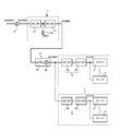
- FIG. 2 shows an example of mounting the uninterruptible power supply 10 having the above-described configuration on the server rack 50.
- the server rack 50 has a size conforming to, for example, the EIA standard, in which a plurality of servers (load devices) 4 can be mounted vertically.
- the power supply unit 20, the first battery unit 30, and the second battery units 40a, 40b, and 40c constituting the uninterruptible power supply device 10 have their circuit portions arranged in independent casings (casings). Each is housed and unitized.
- the power supply unit 20, the first battery unit 30, and the two battery units 40a, 40b among the second battery units 40a, 40b, 40c are the basics of the server rack 50.
- the battery unit 40c is housed in a basic housing size (1U size) housing of the server rack 50 because the third battery 43 having a large capacity is mounted.
- FIG. 2 shows an example of storing the units 20, 30, 40a, 40b, and 40c in the server rack 50.
- the power supply unit 20, the first battery unit 30, and the two second battery units 40 a and 40 b housed in a 1U4 size housing are arranged side by side in one storage stage of the server rack 50. It is put on.
- the second battery unit 40c housed in a 1U size housing is mounted on the lower (or upper) storage stage adjacent to the storage stage on which the power supply unit 20 and the like are mounted.
- the units 20, 30, 40a, 40b, and 40c are connected to the DC terminals that output the DC power (DC 12V) in parallel on the back side of the server rack 50, respectively. It is to build.
- the units 20, 30, 40 a, 40 b, 40 c are connected in parallel to a DC power supply line that is laid on the back side of the server rack 50 and connected to a plurality of servers (load devices) 4. (Not shown), respectively. Then, a DC voltage (DC 12 V) is supplied to the server (load device) 4 through the DC power supply line.
- the connector provided on the back side of each casing of the power supply unit 20 and the battery units 30, 40a, 40b, and 40c comprises one of a plug-in pair of plugs and plug seats.
- the DC power supply line is provided with the other of the plug and the plug seat.
- These plug-in type connectors are connected as the units 20, 30, 40a, 40b, 40c are attached to the server rack 50, and the units 20, 30, 40a, 40b are connected. , 40c are removed from the server rack 50.
- the power supply unit 20 is connected to each phase of the three-phase AC power ( R, S, T) are provided individually.
- the first and second battery units 30, 40a, 40b, and 40c are provided for each of the power supply units 20 for these phases.
- the power supply unit 20 and the battery units 30, 40 a, 40 b for the respective phases (R, S, T) are connected using, for example, six rows of storage stages adjacent in the vertical direction of the server rack 50. Store side by side.
- the power supply unit 20 and the battery units 30, 40a, 40b, and 40c constituting the uninterruptible power supply 10 are coupled to each other via, for example, a connector for serial communication (not shown).
- the units 20, 30, 40a, 40b, and 40c communicate with each other, for example, the load status of the power supply unit 20, the power requirement of the server (load device) 4, and further the AC power supply (AC200V / AC400V).
- the operation of each of the units 20, 30, 40a, 40b, and 40c is controlled in accordance with the power supply situation and the like.
- the server 4 is arranged in the vicinity of the server 4 mounted in the server rack 50, so that the server 4 can be powered without drawing the DC power line. It can be supplied. Therefore, the DC power supply line can be sufficiently shortened while ensuring a necessary minimum wiring length. Therefore, even when a low current (DC12V) large current flows through the DC power supply line, the loss in the DC power supply line can be sufficiently reduced.
- DC12V low current
- the wiring length (laying length) of the DC power supply line from the uninterruptible power supply 10 to the server 4 is short, the wiring inductance can be reduced. Therefore, even when the load power in the server 4 changes abruptly, the operation of the uninterruptible power supply 10 can be made to respond at high speed by following the change. As a result, it is possible to minimize fluctuations in the DC voltage (DC 12 V) supplied to the server 4 and stabilize the DC voltage (DC 12 V).
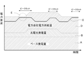
- the power requirement amount of the server (load device) 4 in the data center will be described. Assume that the data center is equipped with private power generation facilities and solar power generation facilities. In this case, the amount of power that the data center can cover is typically the base power generation amount A plus the solar power generation amount B as shown in FIG. Fluctuates depending on.
- the amount of electric power (required electric energy) required for operating (operating) the server (load device) 4 changes to some extent with the passage of time as shown by a solid line C in FIG. 3, for example. .
- the load power amount (required power amount) C exceeds the power amount (total power generation amount) that can be covered in the data center, it is necessary to receive power supply from the power company via the grid power supply.
- the maximum amount of electric power D supplied from an electric power company is specified by a contract or the like, electric power for operating (operating) the server (load device) 4 so as to be surrounded by a broken line E in FIG. There is a possibility that the margin is almost lost.
- the uninterruptible power supply 10 controls the operation of the power supply unit 20 and the battery units 30, 40a, 40b as follows in order to cope with such a change in power situation. .
- the power supply to the battery (load device) 4 can be stabilized while suppressing the burden on the power supply unit 20.
- the operating cost of the uninterruptible power supply 10 with respect to the AC power fed from the electric power company is reduced.
- FIG. 4 shows an operation mode of the uninterruptible power supply 10 when the peak cut control is executed.
- load processing load
- server load device
- power is supplied to the server (load device) 4 only from the power supply unit 20.
- the AC power supplied to the power supply unit 20 is stopped (power failure)
- power is supplied from the first battery unit 30 to the server (load device) 4 instead of the power supply unit 20.
- the direct-current power (DC 12 V) from the first battery unit 30 is supplied by using the direct-current power stored in the high-rate discharge battery 31 having the power capacity of 2.5 kW described above, for example, with a current of 208 A at the maximum. Run over a minute.
- peak cut is performed. Execute control. This peak cut control stops the operation of the power supply unit 20 and the first battery unit 30 provided for power failure countermeasures as shown in FIG. Then, the second battery units 40a, 40b, and 40c are operated, and power is supplied from the second battery units 40a, 40b, and 40c to the server (load device) 4.
- the feeding of DC power (DC12V) from the second battery units 40a, 40b, and 40c is executed for 50 minutes with a maximum current of 167 A, for example.
- the direct-current power (DC12V) fed in this way is the power obtained from the two low-rate discharge batteries 41 that can discharge the above-mentioned small power over a long time, and the small power over a long time. It is obtained as the sum of the electric power obtained from the dischargeable large-capacity low rate charge / discharge battery 43.
- the operation of the power supply unit 20 is stopped, and only the battery unit 40c can be charged with low power. Therefore, apparently, the uninterruptible power supply 10 can be brought into a stopped state with respect to the AC power, and the amount of AC power received can be reduced. And the consumption of the alternating current power in the said uninterruptible power supply 10 can be reduced significantly, keeping the power supply with respect to the said server (load apparatus) 4 stable.
- FIG. In general, in the night time period when the processing load (load) of the server (load device) 4 is reduced and the price of the AC power supplied from the electric power company is reduced, it is shown in FIG.
- the uninterruptible power supply 10 is operated in the form as shown. That is, the power supply unit 20, the first battery unit 30, and the second battery units 40a, 40b, and 40c are operated simultaneously. Then, using the surplus of direct current power fed from the power supply unit 20 to the server (load device) 4, the batteries 31 and 41 of the first battery unit 30 and the second battery units 40a and 40b are connected. Charge each one. At the same time, the battery 43 of the second battery unit 40c is charged using the AC power.
- DC power is stored in each of the first and second battery units 30, 40a, 40b, and 40c, and the above-described operation modes during normal operation and peak cut are provided.
- This demand shift control basically operates only the power supply unit 20 and the first battery unit 30 during normal operation as shown in FIG. 5A, as in the case of the peak cut control described above. Then, the operation of the second battery units 40a, 40b, 40c is suspended.
- the power supply unit 20 When the load on the server (load device) 4 temporarily increases, as shown in FIG. 5B, the power supply unit 20, the first battery unit 30, and the second battery units 40a and 40b. 40c at the same time.
- demand shift control is performed by controlling each output electric power (output current) from each said battery unit 40a, 40b, 40c.
- the demand shift control equalizes the power consumption of the power supply unit 20 per unit time (for example, 30 minutes) when the load of the server (load device) 4 temporarily increases. Therefore, it is executed when the load of the server (load device) 4 increases and the power consumption of the power supply unit 20 exceeds a preset power amount. Then, power is supplied from the second battery units 40a, 40b, and 40c to the server (load device) 4, thereby assisting the power supply from the power supply unit 20. Then, for the power supply unit 20, the amount of power supplied from the power supply unit 20 is reduced by the amount of power supplied from the second battery units 40a, 40b, and 40c to the server (load device) 4. can do.
- the average power supply amount of the power supply unit 20 per unit time for example, 30 minutes
- the power consumption of the power supply unit 20 can be leveled, and the usage amount of the AC power charged according to the average power supply amount per unit time can be reduced.
- the present invention is not limited to the embodiment described above.
- the size of the casing of the power supply unit 20 and the battery units 30, 40 a, and 40 b is divided into a half size obtained by dividing one unit size (1 U size) into two equal parts in the width direction, or three equal parts in the width direction.
- one unit size (1 U size) into two equal parts in the width direction, or three equal parts in the width direction.
- the number of battery units 30, 40a, 40b, 40c connected in parallel to the power supply unit 20 and the power capacity thereof are not particularly limited.
- the present invention can be variously modified and implemented without departing from the scope of the invention.
Landscapes
- Engineering & Computer Science (AREA)
- Power Engineering (AREA)
- Theoretical Computer Science (AREA)
- Physics & Mathematics (AREA)
- General Engineering & Computer Science (AREA)
- General Physics & Mathematics (AREA)
- Business, Economics & Management (AREA)
- Emergency Management (AREA)
- Charge And Discharge Circuits For Batteries Or The Like (AREA)
- Stand-By Power Supply Arrangements (AREA)
- Power Sources (AREA)
Abstract
La présente invention comprend : une unité de source d'alimentation électrique qui convertit le courant alternatif et génère une tension continue qui doit être fournie à un appareil de charge ; une première unité de batterie qui stocke le courant continu en étant raccordée en parallèle à l'unité d'alimentation électrique, et qui génère une tension continue qui doit être fournie à l'appareil de charge lorsque l'entrée du courant alternatif s'arrête ; une seconde unité de batterie qui stocke le courant continu en étant raccordée en parallèle à l'unité d'alimentation électrique, et qui génère une tension continue qui doit être fournie à l'appareil de charge qui correspond à un état de charge de l'unité d'alimentation électrique ; et un moyen de commande qui fait fonctionner, de manière correspondante à une quantité de demande d'énergie de l'appareil de charge, l'unité d'alimentation électrique ainsi que les première et seconde unités de batterie en associant l'unité d'alimentation électrique et les première et seconde unités de batterie les unes aux autres.
Priority Applications (4)
| Application Number | Priority Date | Filing Date | Title |
|---|---|---|---|
| CN201380046903.7A CN104620469B (zh) | 2013-03-15 | 2013-03-15 | 不间断电源装置 |
| PCT/JP2013/057566 WO2014141487A1 (fr) | 2013-03-15 | 2013-03-15 | Appareil de source d'alimentation sans coupure |
| JP2015505214A JP6008040B2 (ja) | 2013-03-15 | 2013-03-15 | 無停電電源装置 |
| US14/642,675 US9673625B2 (en) | 2013-03-15 | 2015-03-09 | Uninterruptible power supply apparatus |
Applications Claiming Priority (1)
| Application Number | Priority Date | Filing Date | Title |
|---|---|---|---|
| PCT/JP2013/057566 WO2014141487A1 (fr) | 2013-03-15 | 2013-03-15 | Appareil de source d'alimentation sans coupure |
Related Child Applications (1)
| Application Number | Title | Priority Date | Filing Date |
|---|---|---|---|
| US14/642,675 Continuation US9673625B2 (en) | 2013-03-15 | 2015-03-09 | Uninterruptible power supply apparatus |
Publications (1)
| Publication Number | Publication Date |
|---|---|
| WO2014141487A1 true WO2014141487A1 (fr) | 2014-09-18 |
Family
ID=51536180
Family Applications (1)
| Application Number | Title | Priority Date | Filing Date |
|---|---|---|---|
| PCT/JP2013/057566 WO2014141487A1 (fr) | 2013-03-15 | 2013-03-15 | Appareil de source d'alimentation sans coupure |
Country Status (4)
| Country | Link |
|---|---|
| US (1) | US9673625B2 (fr) |
| JP (1) | JP6008040B2 (fr) |
| CN (1) | CN104620469B (fr) |
| WO (1) | WO2014141487A1 (fr) |
Cited By (5)
| Publication number | Priority date | Publication date | Assignee | Title |
|---|---|---|---|---|
| WO2016189976A1 (fr) * | 2015-05-25 | 2016-12-01 | 富士電機株式会社 | Dispositif d'alimentation sans coupure et son procédé de commande |
| JP2017150428A (ja) * | 2016-02-26 | 2017-08-31 | 尼寺空圧工業株式会社 | エアーコンプレッサ、エアーコンプレッサの情報表示方法 |
| JP6338808B1 (ja) * | 2017-04-12 | 2018-06-06 | 三菱電機株式会社 | 電力変換装置および非接触給電システム |
| WO2018189953A1 (fr) * | 2017-04-12 | 2018-10-18 | 三菱電機株式会社 | Dispositif de conversion du courant gie et système d'alimentation électrique sans contact |
| CN111433996A (zh) * | 2017-11-28 | 2020-07-17 | Ls电气株式会社 | 分级电力控制系统 |
Families Citing this family (26)
| Publication number | Priority date | Publication date | Assignee | Title |
|---|---|---|---|---|
| EP3176897B1 (fr) * | 2013-07-30 | 2020-11-18 | Fuji Electric Co., Ltd. | Système de source de puissance |
| US10429914B2 (en) | 2013-10-28 | 2019-10-01 | Virtual Power Systems, Inc. | Multi-level data center using consolidated power control |
| WO2015066048A1 (fr) * | 2013-10-28 | 2015-05-07 | Virtual Power Systems, Inc. | Régulation de l'énergie par le biais d'une analyse de puissances requises et d'une activation de sources d'alimentation |
| US9552031B2 (en) * | 2013-12-20 | 2017-01-24 | Facebook, Inc. | Power shelf for computer servers |
| US10637264B2 (en) * | 2014-09-24 | 2020-04-28 | Powertec Solutions International Llc | Portable switching power supply with attachable battery pack and enclosure |
| WO2017006588A1 (fr) * | 2015-07-03 | 2017-01-12 | 富士電機株式会社 | Dispositif d'alimentation |
| US10386421B2 (en) | 2015-09-14 | 2019-08-20 | Facebook, Inc. | Energy based battery backup unit testing |
| US10063092B2 (en) | 2015-10-02 | 2018-08-28 | Facebook, Inc. | Data center power network with multiple redundancies |
| CN106611995B (zh) * | 2015-10-23 | 2019-04-16 | 光宝电子(广州)有限公司 | 具有主动电压调整的不断电电源供电方法及设备 |
| US9622373B1 (en) | 2015-11-13 | 2017-04-11 | Facebook, Inc. | High voltage direct current power system for data centers |
| US9986658B2 (en) | 2015-12-03 | 2018-05-29 | Facebook, Inc | Power connection clip for a shelf in a server rack |
| US9973032B2 (en) | 2015-12-04 | 2018-05-15 | Google Llc | Two-tier battery solution for data center backup |
| US10432017B1 (en) * | 2016-03-15 | 2019-10-01 | Amazon Technologies, Inc. | Uninterruptable power supply (UPS) management |
| US10642329B2 (en) * | 2016-03-23 | 2020-05-05 | Qualcomm Incorporated | Peak current support for a power rail system via a shared secondary power supply |
| US10404062B2 (en) * | 2016-04-21 | 2019-09-03 | Nuscale Power, Llc | Fault-tolerant power-distribution modules for a power plant |
| US10123450B2 (en) | 2016-05-12 | 2018-11-06 | Facebook, Inc. | High voltage direct current power generator for computer server data centers |
| CN109196761B (zh) * | 2016-06-02 | 2021-01-12 | 株式会社村田制作所 | 电源系统 |
| TWM540306U (zh) * | 2016-10-05 | 2017-04-21 | Etasis Electronics Corp | 電源分配裝置 |
| CN106684995A (zh) * | 2017-01-04 | 2017-05-17 | 北京百度网讯科技有限公司 | 供电系统及其供电控制方法 |
| JP6935592B2 (ja) * | 2018-07-04 | 2021-09-15 | 東芝三菱電機産業システム株式会社 | 無停電電源装置 |
| CN109936127B (zh) * | 2019-04-23 | 2021-08-13 | 北京百度网讯科技有限公司 | 数据中心的配电方法、装置、设备和系统 |
| US10978886B2 (en) * | 2019-07-17 | 2021-04-13 | Baidu Usa Llc | Self-inspection topology design for battery energy storage |
| US11735948B2 (en) * | 2019-07-26 | 2023-08-22 | Baidu Usa Llc | Bi-directional multi-function converter for backup battery unit |
| WO2021088862A1 (fr) * | 2019-11-04 | 2021-05-14 | 苏州宝时得电动工具有限公司 | Dispositif d'alimentation électrique et procédé de commande associé |
| CN111049255B (zh) * | 2019-11-28 | 2023-07-28 | 广西电网有限责任公司南宁供电局 | 一种缓冲式不间断电源并联功率分配系统 |
| JP2024511382A (ja) * | 2021-03-17 | 2024-03-13 | ファーウェイ デジタル パワー テクノロジーズ カンパニー リミテッド | エネルギ貯蔵システム及びバッテリ管理システムの電力供給方法 |
Citations (7)
| Publication number | Priority date | Publication date | Assignee | Title |
|---|---|---|---|---|
| JPH01180836U (fr) * | 1988-05-30 | 1989-12-26 | ||
| JPH05276690A (ja) * | 1992-03-26 | 1993-10-22 | Fuji Electric Co Ltd | 電流制限機能付無停電電源装置 |
| JPH06261469A (ja) * | 1993-03-08 | 1994-09-16 | Fujitsu Ltd | バックアップ電源装置 |
| JP2005227017A (ja) * | 2004-02-10 | 2005-08-25 | Toshiba Corp | 原子力発電所の直流電源システム |
| WO2011135712A1 (fr) * | 2010-04-30 | 2011-11-03 | 富士通株式会社 | Source d'alimentation non interruptible, procédé d'utilisation associé et système serveur |
| JP2012130158A (ja) * | 2010-12-15 | 2012-07-05 | Nippon Telegr & Teleph Corp <Ntt> | 電源装置 |
| JP2013051879A (ja) * | 2006-07-13 | 2013-03-14 | Univ Of Tsukuba | 電源システム |
Family Cites Families (25)
| Publication number | Priority date | Publication date | Assignee | Title |
|---|---|---|---|---|
| JPH05207682A (ja) * | 1992-01-24 | 1993-08-13 | Yuasa Corp | 無停電電源装置 |
| JP3250354B2 (ja) | 1993-12-24 | 2002-01-28 | オムロン株式会社 | 電源装置 |
| FR2721728B1 (fr) * | 1994-06-28 | 1996-07-26 | Bull Sa | Procédé et dispositif de génération automatique de feuilles de calcul. |
| US5745356A (en) * | 1996-06-25 | 1998-04-28 | Exide Electronics Corporation | Independent load sharing of AC power systems connected in parallel |
| JP3043973U (ja) | 1997-03-05 | 1997-12-12 | 信和 西村 | 電力分散化電源装置 |
| US6215202B1 (en) * | 1998-05-21 | 2001-04-10 | Bechtel Enterprises Inc. | Shunt connected superconducting energy management system having a single switchable connection to the grid |
| JP2001103663A (ja) * | 1999-09-27 | 2001-04-13 | Daikin Ind Ltd | 蓄電電気機器システムにおける放電制御方法およびその装置 |
| JP3695641B2 (ja) * | 2000-12-19 | 2005-09-14 | 日本電信電話株式会社 | 電力供給システム |
| EP1311048A3 (fr) * | 2001-11-09 | 2005-02-16 | Matsushita Electric Industrial Co., Ltd. | Dispositif pour le réglage de puissance, système de production d'énergie et procédé pour le control du dispositif de réglage |
| US6949843B2 (en) * | 2003-07-11 | 2005-09-27 | Morningstar, Inc. | Grid-connected power systems having back-up power sources and methods of providing back-up power in grid-connected power systems |
| JP2006230029A (ja) | 2005-02-15 | 2006-08-31 | Hitachi Ltd | 無停電電源装置 |
| US7547990B2 (en) * | 2005-07-12 | 2009-06-16 | Diran Varzhabedian | Backup power system for electrical appliances |
| JP5033697B2 (ja) * | 2008-03-31 | 2012-09-26 | 株式会社日立製作所 | 家庭用充放電装置及びその制御方法 |
| US8344545B2 (en) * | 2009-01-20 | 2013-01-01 | Honeywell International Inc. | Solid state power contactors based on no break power transfer method |
| CN101902056B (zh) * | 2009-06-01 | 2015-06-17 | Ge医疗系统环球技术有限公司 | 不间断电源和使不间断电源省电的方法 |
| KR101369697B1 (ko) * | 2009-09-16 | 2014-03-04 | 도시바 미쓰비시덴키 산교시스템 가부시키가이샤 | 전력 변환 시스템 및 무정전 전원 시스템 |
| JP5507946B2 (ja) * | 2009-10-05 | 2014-05-28 | パナソニック株式会社 | バッテリ制御ユニット |
| JP2011211791A (ja) * | 2010-03-29 | 2011-10-20 | Toshiba Mach Co Ltd | バックアップ電源装置及び電力出力方法 |
| JP5556422B2 (ja) * | 2010-06-23 | 2014-07-23 | 東京電力株式会社 | 蓄電池システム |
| US8422256B2 (en) * | 2010-07-30 | 2013-04-16 | General Electric Company | Control system for high-efficiency operation in parallel inverter installations |
| CN102593942A (zh) * | 2011-01-04 | 2012-07-18 | 中兴电工机械股份有限公司 | 电力供应系统及其燃料电池备援电力系统 |
| JP5687498B2 (ja) | 2011-01-05 | 2015-03-18 | 株式会社Nttファシリティーズ | 電力変換システム |
| JP5866770B2 (ja) * | 2011-02-17 | 2016-02-17 | 富士電機株式会社 | 電源装置 |
| CN102738844A (zh) * | 2011-04-15 | 2012-10-17 | 郑茂振 | 在线互动式电源控制系统 |
| CN102355042B (zh) * | 2011-09-14 | 2013-10-09 | 南京天溯自动化控制系统有限公司 | 一种基于超级电容的电站直流电源装置及其供电方法 |
-
2013
- 2013-03-15 CN CN201380046903.7A patent/CN104620469B/zh not_active Expired - Fee Related
- 2013-03-15 WO PCT/JP2013/057566 patent/WO2014141487A1/fr active Application Filing
- 2013-03-15 JP JP2015505214A patent/JP6008040B2/ja not_active Expired - Fee Related
-
2015
- 2015-03-09 US US14/642,675 patent/US9673625B2/en not_active Expired - Fee Related
Patent Citations (7)
| Publication number | Priority date | Publication date | Assignee | Title |
|---|---|---|---|---|
| JPH01180836U (fr) * | 1988-05-30 | 1989-12-26 | ||
| JPH05276690A (ja) * | 1992-03-26 | 1993-10-22 | Fuji Electric Co Ltd | 電流制限機能付無停電電源装置 |
| JPH06261469A (ja) * | 1993-03-08 | 1994-09-16 | Fujitsu Ltd | バックアップ電源装置 |
| JP2005227017A (ja) * | 2004-02-10 | 2005-08-25 | Toshiba Corp | 原子力発電所の直流電源システム |
| JP2013051879A (ja) * | 2006-07-13 | 2013-03-14 | Univ Of Tsukuba | 電源システム |
| WO2011135712A1 (fr) * | 2010-04-30 | 2011-11-03 | 富士通株式会社 | Source d'alimentation non interruptible, procédé d'utilisation associé et système serveur |
| JP2012130158A (ja) * | 2010-12-15 | 2012-07-05 | Nippon Telegr & Teleph Corp <Ntt> | 電源装置 |
Cited By (7)
| Publication number | Priority date | Publication date | Assignee | Title |
|---|---|---|---|---|
| WO2016189976A1 (fr) * | 2015-05-25 | 2016-12-01 | 富士電機株式会社 | Dispositif d'alimentation sans coupure et son procédé de commande |
| JPWO2016189976A1 (ja) * | 2015-05-25 | 2017-10-05 | 富士電機株式会社 | 無停電電源装置および該装置の制御方法 |
| US10374453B2 (en) | 2015-05-25 | 2019-08-06 | Fuji Electric Co., Ltd. | Uninterruptible power supply and control method there of |
| JP2017150428A (ja) * | 2016-02-26 | 2017-08-31 | 尼寺空圧工業株式会社 | エアーコンプレッサ、エアーコンプレッサの情報表示方法 |
| JP6338808B1 (ja) * | 2017-04-12 | 2018-06-06 | 三菱電機株式会社 | 電力変換装置および非接触給電システム |
| WO2018189953A1 (fr) * | 2017-04-12 | 2018-10-18 | 三菱電機株式会社 | Dispositif de conversion du courant gie et système d'alimentation électrique sans contact |
| CN111433996A (zh) * | 2017-11-28 | 2020-07-17 | Ls电气株式会社 | 分级电力控制系统 |
Also Published As
| Publication number | Publication date |
|---|---|
| US20150180233A1 (en) | 2015-06-25 |
| JPWO2014141487A1 (ja) | 2017-02-16 |
| CN104620469A (zh) | 2015-05-13 |
| JP6008040B2 (ja) | 2016-10-19 |
| US9673625B2 (en) | 2017-06-06 |
| CN104620469B (zh) | 2018-03-30 |
Similar Documents
| Publication | Publication Date | Title |
|---|---|---|
| JP6008040B2 (ja) | 無停電電源装置 | |
| JP6048572B2 (ja) | 無停電電源装置 | |
| Shi et al. | Constant current fast charging of electric vehicles via a DC grid using a dual-inverter drive | |
| US11532947B2 (en) | Combination wind/solar DC power system | |
| CN103636094B (zh) | 用于临界电力应用的b侧馈送 | |
| JP6086867B2 (ja) | 燃料電池制御装置および方法 | |
| US6369463B1 (en) | Apparatus and method for supplying alternative energy and back-up emergency power to electrical devices | |
| JP2011120449A (ja) | 発電システム、制御装置および切替回路 | |
| JP6070819B2 (ja) | 電源システム | |
| CN109927588B (zh) | 对具有至少两个充电点的车辆充电的充电站的变压器装置 | |
| JPWO2010035338A1 (ja) | 電力変換装置 | |
| CN108233421A (zh) | 光伏发电系统和光伏输电方法 | |
| US9570939B2 (en) | Double-port energy storage system and control method thereof | |
| KR20170118285A (ko) | 가변 전압 dc 마이크로그리드 시스템 및 이의 운전 방법 | |
| US20190267811A1 (en) | Method and system for generation and distribution of high voltage direct current | |
| CN102593938A (zh) | 整机柜及用于其的集中供电装置 | |
| JP2017184607A (ja) | 配電システム及び電力合成回路 | |
| KR20210138662A (ko) | 다중 포트 전력 변환기 장치 | |
| JP2010110056A (ja) | 配電システム | |
| US10886744B2 (en) | Power conversion system, power supply system and power conversion device | |
| CN105529746B (zh) | 一种柔性配电系统 | |
| JP5734356B2 (ja) | 電力変換装置 | |
| JP7221634B2 (ja) | 受電設備 | |
| KR101516278B1 (ko) | 쓰러스터 구동을 위한 선박의 전력 시스템 | |
| CN112953261A (zh) | 供电装置和数据处理设备 |
Legal Events
| Date | Code | Title | Description |
|---|---|---|---|
| 121 | Ep: the epo has been informed by wipo that ep was designated in this application |
Ref document number: 13877963 Country of ref document: EP Kind code of ref document: A1 |
|
| ENP | Entry into the national phase |
Ref document number: 2015505214 Country of ref document: JP Kind code of ref document: A |
|
| NENP | Non-entry into the national phase |
Ref country code: DE |
|
| 122 | Ep: pct application non-entry in european phase |
Ref document number: 13877963 Country of ref document: EP Kind code of ref document: A1 |