WO2014136670A1 - 基板処理装置及び基板処理方法 - Google Patents
基板処理装置及び基板処理方法 Download PDFInfo
- Publication number
- WO2014136670A1 WO2014136670A1 PCT/JP2014/055054 JP2014055054W WO2014136670A1 WO 2014136670 A1 WO2014136670 A1 WO 2014136670A1 JP 2014055054 W JP2014055054 W JP 2014055054W WO 2014136670 A1 WO2014136670 A1 WO 2014136670A1
- Authority
- WO
- WIPO (PCT)
- Prior art keywords
- substrate
- volatile solvent
- unit
- liquid
- heating
- Prior art date
Links
- 239000000758 substrate Substances 0.000 title claims abstract description 280
- 238000012545 processing Methods 0.000 title claims abstract description 117
- 238000003672 processing method Methods 0.000 title claims description 11
- 239000002904 solvent Substances 0.000 claims abstract description 85
- 238000010438 heat treatment Methods 0.000 claims abstract description 50
- 230000007246 mechanism Effects 0.000 claims description 35
- 239000007788 liquid Substances 0.000 abstract description 103
- 230000006870 function Effects 0.000 abstract description 4
- 230000001678 irradiating effect Effects 0.000 abstract description 4
- 239000007789 gas Substances 0.000 description 66
- 238000001035 drying Methods 0.000 description 39
- KFZMGEQAYNKOFK-UHFFFAOYSA-N Isopropanol Chemical compound CC(C)O KFZMGEQAYNKOFK-UHFFFAOYSA-N 0.000 description 33
- 230000032258 transport Effects 0.000 description 24
- 238000012546 transfer Methods 0.000 description 13
- 238000007664 blowing Methods 0.000 description 10
- 229910021642 ultra pure water Inorganic materials 0.000 description 10
- 239000012498 ultrapure water Substances 0.000 description 10
- 238000009835 boiling Methods 0.000 description 8
- IJGRMHOSHXDMSA-UHFFFAOYSA-N Atomic nitrogen Chemical compound N#N IJGRMHOSHXDMSA-UHFFFAOYSA-N 0.000 description 7
- 230000006837 decompression Effects 0.000 description 7
- 229910001873 dinitrogen Inorganic materials 0.000 description 7
- 239000012298 atmosphere Substances 0.000 description 5
- 230000000694 effects Effects 0.000 description 5
- 230000002093 peripheral effect Effects 0.000 description 5
- 238000000034 method Methods 0.000 description 4
- 230000008569 process Effects 0.000 description 4
- RTZKZFJDLAIYFH-UHFFFAOYSA-N Diethyl ether Chemical compound CCOCC RTZKZFJDLAIYFH-UHFFFAOYSA-N 0.000 description 3
- 230000015572 biosynthetic process Effects 0.000 description 3
- 238000004140 cleaning Methods 0.000 description 3
- 239000011261 inert gas Substances 0.000 description 3
- 239000000463 material Substances 0.000 description 3
- 239000012299 nitrogen atmosphere Substances 0.000 description 3
- 239000004065 semiconductor Substances 0.000 description 3
- 238000005507 spraying Methods 0.000 description 3
- XLYOFNOQVPJJNP-UHFFFAOYSA-N water Substances O XLYOFNOQVPJJNP-UHFFFAOYSA-N 0.000 description 3
- XKRFYHLGVUSROY-UHFFFAOYSA-N Argon Chemical compound [Ar] XKRFYHLGVUSROY-UHFFFAOYSA-N 0.000 description 2
- CURLTUGMZLYLDI-UHFFFAOYSA-N Carbon dioxide Chemical compound O=C=O CURLTUGMZLYLDI-UHFFFAOYSA-N 0.000 description 2
- LFQSCWFLJHTTHZ-UHFFFAOYSA-N Ethanol Chemical compound CCO LFQSCWFLJHTTHZ-UHFFFAOYSA-N 0.000 description 2
- MHAJPDPJQMAIIY-UHFFFAOYSA-N Hydrogen peroxide Chemical compound OO MHAJPDPJQMAIIY-UHFFFAOYSA-N 0.000 description 2
- QAOWNCQODCNURD-UHFFFAOYSA-N Sulfuric acid Chemical compound OS(O)(=O)=O QAOWNCQODCNURD-UHFFFAOYSA-N 0.000 description 2
- 230000001174 ascending effect Effects 0.000 description 2
- QVGXLLKOCUKJST-UHFFFAOYSA-N atomic oxygen Chemical compound [O] QVGXLLKOCUKJST-UHFFFAOYSA-N 0.000 description 2
- -1 for example Chemical compound 0.000 description 2
- 239000004973 liquid crystal related substance Substances 0.000 description 2
- 238000004519 manufacturing process Methods 0.000 description 2
- 239000001301 oxygen Substances 0.000 description 2
- 229910052760 oxygen Inorganic materials 0.000 description 2
- 239000010409 thin film Substances 0.000 description 2
- 238000009834 vaporization Methods 0.000 description 2
- 230000008016 vaporization Effects 0.000 description 2
- VHUUQVKOLVNVRT-UHFFFAOYSA-N Ammonium hydroxide Chemical compound [NH4+].[OH-] VHUUQVKOLVNVRT-UHFFFAOYSA-N 0.000 description 1
- XOBKSJJDNFUZPF-UHFFFAOYSA-N Methoxyethane Chemical compound CCOC XOBKSJJDNFUZPF-UHFFFAOYSA-N 0.000 description 1
- 206010037660 Pyrexia Diseases 0.000 description 1
- 150000001298 alcohols Chemical class 0.000 description 1
- 235000011114 ammonium hydroxide Nutrition 0.000 description 1
- 238000013459 approach Methods 0.000 description 1
- 229910052786 argon Inorganic materials 0.000 description 1
- 239000001569 carbon dioxide Substances 0.000 description 1
- 229910002092 carbon dioxide Inorganic materials 0.000 description 1
- 238000007599 discharging Methods 0.000 description 1
- 230000005489 elastic deformation Effects 0.000 description 1
- 150000002170 ethers Chemical class 0.000 description 1
- 230000002349 favourable effect Effects 0.000 description 1
- 239000010408 film Substances 0.000 description 1
- 239000012530 fluid Substances 0.000 description 1
- 229910052736 halogen Inorganic materials 0.000 description 1
- 150000002367 halogens Chemical class 0.000 description 1
- 239000001307 helium Substances 0.000 description 1
- 229910052734 helium Inorganic materials 0.000 description 1
- SWQJXJOGLNCZEY-UHFFFAOYSA-N helium atom Chemical compound [He] SWQJXJOGLNCZEY-UHFFFAOYSA-N 0.000 description 1
- 230000010354 integration Effects 0.000 description 1
- 239000011259 mixed solution Substances 0.000 description 1
- 238000012986 modification Methods 0.000 description 1
- 230000004048 modification Effects 0.000 description 1
- 239000003960 organic solvent Substances 0.000 description 1
- 238000002360 preparation method Methods 0.000 description 1
- 239000010453 quartz Substances 0.000 description 1
- VYPSYNLAJGMNEJ-UHFFFAOYSA-N silicon dioxide Inorganic materials O=[Si]=O VYPSYNLAJGMNEJ-UHFFFAOYSA-N 0.000 description 1
- 238000003860 storage Methods 0.000 description 1
- 238000011144 upstream manufacturing Methods 0.000 description 1
- 229910052724 xenon Inorganic materials 0.000 description 1
- FHNFHKCVQCLJFQ-UHFFFAOYSA-N xenon atom Chemical compound [Xe] FHNFHKCVQCLJFQ-UHFFFAOYSA-N 0.000 description 1
Images


Classifications
-
- F—MECHANICAL ENGINEERING; LIGHTING; HEATING; WEAPONS; BLASTING
- F26—DRYING
- F26B—DRYING SOLID MATERIALS OR OBJECTS BY REMOVING LIQUID THEREFROM
- F26B3/00—Drying solid materials or objects by processes involving the application of heat
- F26B3/28—Drying solid materials or objects by processes involving the application of heat by radiation, e.g. from the sun
- F26B3/30—Drying solid materials or objects by processes involving the application of heat by radiation, e.g. from the sun from infrared-emitting elements
-
- F—MECHANICAL ENGINEERING; LIGHTING; HEATING; WEAPONS; BLASTING
- F26—DRYING
- F26B—DRYING SOLID MATERIALS OR OBJECTS BY REMOVING LIQUID THEREFROM
- F26B11/00—Machines or apparatus for drying solid materials or objects with movement which is non-progressive
- F26B11/18—Machines or apparatus for drying solid materials or objects with movement which is non-progressive on or in moving dishes, trays, pans, or other mainly-open receptacles
-
- F—MECHANICAL ENGINEERING; LIGHTING; HEATING; WEAPONS; BLASTING
- F26—DRYING
- F26B—DRYING SOLID MATERIALS OR OBJECTS BY REMOVING LIQUID THEREFROM
- F26B3/00—Drying solid materials or objects by processes involving the application of heat
- F26B3/28—Drying solid materials or objects by processes involving the application of heat by radiation, e.g. from the sun
-
- F—MECHANICAL ENGINEERING; LIGHTING; HEATING; WEAPONS; BLASTING
- F26—DRYING
- F26B—DRYING SOLID MATERIALS OR OBJECTS BY REMOVING LIQUID THEREFROM
- F26B5/00—Drying solid materials or objects by processes not involving the application of heat
- F26B5/005—Drying solid materials or objects by processes not involving the application of heat by dipping them into or mixing them with a chemical liquid, e.g. organic; chemical, e.g. organic, dewatering aids
-
- F—MECHANICAL ENGINEERING; LIGHTING; HEATING; WEAPONS; BLASTING
- F26—DRYING
- F26B—DRYING SOLID MATERIALS OR OBJECTS BY REMOVING LIQUID THEREFROM
- F26B7/00—Drying solid materials or objects by processes using a combination of processes not covered by a single one of groups F26B3/00 and F26B5/00
-
- H—ELECTRICITY
- H01—ELECTRIC ELEMENTS
- H01L—SEMICONDUCTOR DEVICES NOT COVERED BY CLASS H10
- H01L21/00—Processes or apparatus adapted for the manufacture or treatment of semiconductor or solid state devices or of parts thereof
- H01L21/02—Manufacture or treatment of semiconductor devices or of parts thereof
- H01L21/02041—Cleaning
- H01L21/02057—Cleaning during device manufacture
-
- H—ELECTRICITY
- H01—ELECTRIC ELEMENTS
- H01L—SEMICONDUCTOR DEVICES NOT COVERED BY CLASS H10
- H01L21/00—Processes or apparatus adapted for the manufacture or treatment of semiconductor or solid state devices or of parts thereof
- H01L21/67—Apparatus specially adapted for handling semiconductor or electric solid state devices during manufacture or treatment thereof; Apparatus specially adapted for handling wafers during manufacture or treatment of semiconductor or electric solid state devices or components ; Apparatus not specifically provided for elsewhere
- H01L21/67005—Apparatus not specifically provided for elsewhere
- H01L21/67011—Apparatus for manufacture or treatment
- H01L21/67017—Apparatus for fluid treatment
- H01L21/67028—Apparatus for fluid treatment for cleaning followed by drying, rinsing, stripping, blasting or the like
- H01L21/67034—Apparatus for fluid treatment for cleaning followed by drying, rinsing, stripping, blasting or the like for drying
-
- H—ELECTRICITY
- H01—ELECTRIC ELEMENTS
- H01L—SEMICONDUCTOR DEVICES NOT COVERED BY CLASS H10
- H01L21/00—Processes or apparatus adapted for the manufacture or treatment of semiconductor or solid state devices or of parts thereof
- H01L21/67—Apparatus specially adapted for handling semiconductor or electric solid state devices during manufacture or treatment thereof; Apparatus specially adapted for handling wafers during manufacture or treatment of semiconductor or electric solid state devices or components ; Apparatus not specifically provided for elsewhere
- H01L21/67005—Apparatus not specifically provided for elsewhere
- H01L21/67011—Apparatus for manufacture or treatment
- H01L21/67098—Apparatus for thermal treatment
- H01L21/67115—Apparatus for thermal treatment mainly by radiation
Definitions
- Embodiments described herein relate generally to a substrate processing apparatus and a substrate processing method.
- the substrate processing apparatus is an apparatus for supplying a processing liquid to the surface of a substrate such as a wafer or a liquid crystal substrate to process the substrate surface in a manufacturing process of a semiconductor or the like, and then drying the substrate surface.
- a processing liquid to the surface of a substrate such as a wafer or a liquid crystal substrate to process the substrate surface in a manufacturing process of a semiconductor or the like, and then drying the substrate surface.
- this drying process there is a problem that, for example, the pattern around the memory cell and the gate collapses due to the miniaturization accompanying the recent high integration and high capacity of the semiconductor. This is due to the spacing and structure between patterns, the surface tension of the treatment liquid, and the like.
- the drying speed of the substrate surface becomes uneven, and if the liquid remains between some patterns, the pattern collapses due to the surface tension of the liquid in that part.
- the pattern of the remaining part of the liquid collapses due to elastic deformation due to the surface tension of the liquid, the slightly dissolved residue aggregates in the liquid, and then the liquid completely vaporizes, so that the collapsed patterns adhere to each other. Will collapse.
- the problem to be solved by the present invention is to provide a substrate processing apparatus and a substrate processing method capable of performing good substrate drying while suppressing collapse of a pattern.
- a solvent supply unit that supplies a volatile solvent to the surface of the substrate, and a gas layer is generated on the surface of the substrate to which the volatile solvent is supplied so that the volatile solvent is liquefied.
- a heating unit for heating the substrate.
- the substrate processing method includes a step of supplying a volatile solvent to the surface of the substrate, and forming a gas layer on the surface of the substrate to which the volatile solvent is supplied so that the volatile solvent is liquefied. Heating.
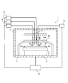
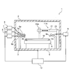
- the substrate processing apparatus 1 includes a processing box 2 serving as a processing chamber, a cup 3 provided in the processing box 2, and a substrate W in the cup 3.
- a table 4 that is supported in a horizontal state and a rotating mechanism 5 that rotates the table 4 in a horizontal plane are provided.
- the substrate processing apparatus 1 includes a first processing liquid supply unit 6 that supplies a first processing liquid to the surface of the substrate W on the table 4, and a second processing liquid on the surface of the substrate W on the table 4.
- a second processing liquid supply unit 7 to be supplied, a solvent supply unit 8 to supply a volatile solvent, a gas supply unit 9 to supply a gas, an irradiation unit 10 that emits light, and the irradiation unit 10 are moved.
- the moving mechanism 11 and the control part 12 which controls each part are provided.
- the cup 3 is formed in a cylindrical shape, and surrounds the table 4 from the periphery and accommodates it inside.
- the upper part of the peripheral wall of the cup 3 is inclined toward the inside in the radial direction, and is opened so that the substrate W on the table 4 is exposed.
- the cup 3 receives the processing liquid that has flowed down or scattered from the rotating substrate W.
- a discharge pipe (not shown) for discharging the received processing liquid is provided at the bottom of the cup 3.
- the table 4 is positioned near the center in the cup 3 and is provided to be rotatable in a horizontal plane.
- the table 4 has a plurality of support members 4a such as pins, and these support members 4a hold a substrate W such as a wafer or a liquid crystal substrate in a detachable manner.
- the rotating mechanism 5 includes a rotating shaft coupled to the table 4 and a motor (none of which is shown) serving as a driving source for rotating the rotating shaft, and the table 4 is driven by the motor via the rotating shaft. Rotate.
- the rotation mechanism 5 is electrically connected to the control unit 12, and the driving thereof is controlled by the control unit 12.
- the first processing liquid supply unit 6 includes a nozzle 6 a that discharges the first processing liquid from an oblique direction with respect to the surface of the substrate W on the table 4, and the substrate W on the table 4 from the nozzle 6 a.
- a first treatment liquid for example, APM (a mixed solution of ammonia water and hydrogen peroxide solution) for resist removal treatment is supplied to the surface of the substrate.
- the nozzle 6 a is mounted on the upper part of the peripheral wall of the cup 3, and its angle and discharge flow rate are adjusted so that the first processing liquid is supplied near the center of the surface of the substrate W.
- the first processing liquid supply unit 6 is electrically connected to the control unit 12, and the driving thereof is controlled by the control unit 12.
- the first processing liquid supply unit 6 includes a tank that stores the first processing liquid, a pump that is a driving source, a valve that is an adjustment valve that adjusts the supply amount (none of which are shown), and the like. .
- the second processing liquid supply unit 7 includes a nozzle 7 a that discharges the second processing liquid from an oblique direction with respect to the surface of the substrate W on the table 4, and the substrate W on the table 4 from the nozzle 7 a.
- a second treatment liquid for example, pure water for cleaning treatment (ultra pure water) is supplied to the surface of.
- the nozzle 7 a is mounted on the upper part of the peripheral wall of the cup 3, and its angle and discharge flow rate are adjusted so that the second processing liquid is supplied near the center of the surface of the substrate W.
- the second processing liquid supply unit 7 is electrically connected to the control unit 12, and its driving is controlled by the control unit 12.
- the second processing liquid supply unit 7 includes a tank that stores the second processing liquid, a pump that serves as a drive source, a valve that serves as an adjustment valve that adjusts the supply amount (none of which are shown), and the like. .
- the solvent supply unit 8 has a nozzle 8 a that discharges a volatile solvent from an oblique direction with respect to the surface of the substrate W on the table 4, and the volatile solvent is applied from the nozzle 8 a to the surface of the substrate W on the table 4.
- IPA is supplied.
- the nozzle 8 a is mounted on the upper part of the peripheral wall of the cup 3, and its angle and discharge flow rate are adjusted so that the volatile solvent is supplied near the center of the surface of the substrate W.
- the solvent supply unit 8 is electrically connected to the control unit 12, and its driving is controlled by the control unit 12.
- the solvent supply unit 8 includes a tank that stores a volatile solvent, a pump that is a driving source, a valve that is an adjustment valve that adjusts the supply amount (none of which is shown), and the like.
- IPA for example, monovalent alcohols such as ethanol, ethers such as diethyl ether and ethyl methyl ether, and the like can be used as the volatile solvent.
- the volatile solvent is preferably soluble in water.
- the gas supply unit 9 has a nozzle 9 a that discharges gas from an oblique direction with respect to the surface of the substrate W on the table 4. To make the space on the surface of the substrate W into a nitrogen gas atmosphere.
- the nozzle 9 a is mounted on the upper part of the peripheral wall of the cup 3, and its angle and discharge flow rate are adjusted so that gas is supplied near the center of the surface of the substrate W.
- the gas supply unit 9 is electrically connected to the control unit 12, and its driving is controlled by the control unit 12.
- the gas supply unit 9 includes a tank that stores gas, a valve that is an adjustment valve that adjusts the supply amount (none of which is shown), and the like.
- an inert gas other than nitrogen gas for example, argon gas, carbon dioxide gas, helium gas, or the like can be used. Since this inert gas is supplied to the surface of the substrate W, it is possible to remove oxygen on the surface of the substrate W and prevent the generation of watermarks (water spots).
- the gas to be supplied is preferably a heated gas.
- the irradiation unit 10 has a plurality of lamps 10a, is provided above the table 4, and irradiates the surface of the substrate W on the table 4 with light by turning on each lamp 10a.
- the irradiation unit 10 is configured to be movable in the vertical direction (lifting direction) by the moving mechanism 11, and the irradiation position close to the cup 3 (position close to the surface of the substrate W as shown by the solid line in FIG. 1). ) And a standby position separated from the cup 3 by a predetermined distance (position separated from the surface of the substrate W as indicated by a one-dot chain line in FIG. 1).
- the irradiation unit 10 is electrically connected to the control unit 12, and its driving is controlled by the control unit 12.
- the irradiating unit 10 for example, a unit in which a plurality of straight tube type lamps 10a are provided in parallel or a unit in which a plurality of light bulb type lamps 10a are provided in an array can be used.
- the lamp 10a for example, a halogen lamp or a xenon flash lamp (for example, a flash lamp having a wavelength of 400 to 1000 nm) can be used.
- the irradiation unit 10 functions as a heating unit that heats the substrate W.
- various irradiation units that irradiate the substrate W on the table 4 with an electromagnetic wave can be used.
- the lamp 10 a that irradiates light for example, the substrate on the table 4
- a far-red heater that irradiates W with far-infrared rays, a microwave heater that irradiates microwaves, or the like can be used.
- the moving mechanism 11 includes a holding unit that holds the irradiation unit 10, a mechanism that moves the holding unit in the ascending / descending direction of the irradiation unit 10, a motor (not shown) that serves as a drive source, and the like.
- the irradiation unit 10 is moved together with the holding unit by driving.
- the moving mechanism 11 is electrically connected to the control unit 12, and its driving is controlled by the control unit 12.
- the control unit 12 includes a microcomputer that centrally controls each unit, and a storage unit that stores substrate processing information and various programs related to substrate processing. This control unit 12 is based on the substrate processing information and various programs, and includes the rotation mechanism 5, the first processing liquid supply unit 6, the second processing liquid supply unit 7, the solvent supply unit 8, the gas supply unit 9, and the irradiation unit 10.
- the first processing liquid supply unit 6 supplies the first processing liquid to the surface of the substrate W on the rotating table 4 and the second processing liquid supply unit 7 controls the moving mechanism 11 and the like. 2, supply of a volatile solvent by the solvent supply unit 8, supply of a gas by the gas supply unit 9, and irradiation (heating) by the irradiation unit 10 are performed.
- the substrate W is set on the table 4 and the preparation is completed.
- the irradiation unit 10 stands by at a standby position (see the alternate long and short dash line in FIG. 1) separated from the cup 3 by a predetermined distance.
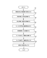
- the control unit 12 controls the rotation mechanism 5 to rotate the table 4 at a predetermined number of rotations (step S1), and then controls the first processing liquid supply unit 6 to rotate.
- the first processing liquid that is, APM
- APM is supplied for a predetermined time from the first nozzle 6a to the surface of the substrate W on the table 4 (step S2).
- APM as the first processing liquid is discharged from the first nozzle 6a toward the center of the substrate W on the rotating table 4, and spreads over the entire surface of the substrate W due to the centrifugal force generated by the rotation of the substrate W. .
- the surface of the substrate W on the table 4 is covered with the APM and processed.
- the processing conditions such as the number of rotations and the predetermined time of the table 4 are set in advance, but can be arbitrarily changed by the operator.
- step S ⁇ b> 2 the control unit 12 stops the supply of the first processing liquid, and then controls the second processing liquid supply unit 7, so that the second nozzle is formed on the surface of the substrate W on the rotating table 4.
- a second processing liquid that is, ultrapure water is supplied from 7a for a predetermined time (step S3).
- the ultrapure water as the second treatment liquid is discharged from the second nozzle 7a toward the center of the substrate W on the rotating table 4, and spreads over the entire surface of the substrate W by the centrifugal force generated by the rotation of the substrate W. To go. As a result, the surface of the substrate W on the table 4 is covered and cleaned with the ultrapure water.
- step S3 the control unit 12 stops the supply of the second processing liquid, then controls the moving mechanism 11, lowers the irradiation unit 10 from the standby position to the irradiation position, and further turns the gas supply unit 9 on.
- a controlled gas is supplied from the nozzle 9a to the surface of the substrate W on the rotating table 4 for a predetermined time (step S4). At this time, each lamp 10a of the irradiation unit 10 is not turned on. Nitrogen gas is discharged from the nozzle 9 a toward the center of the substrate W on the rotating table 4, and spreads over the entire surface of the substrate W due to the airflow generated by the rotation of the substrate W.
- the space between the surface of the substrate W on the table 4 and the irradiation unit 10 becomes a nitrogen atmosphere.
- the oxygen concentration can be reduced and the generation of watermarks on the surface of the substrate W can be suppressed.
- the space between the surface of the substrate W on the table 4 and the irradiation unit 10 is narrowed when the irradiation unit 10 is moved from the standby position to the irradiation position, the time for the space to be a nitrogen atmosphere is shortened. The entire processing time can be shortened.
- step S4 the control unit 12 stops the supply of nitrogen gas, and then controls the solvent supply unit 8, and a predetermined amount of volatile solvent, that is, IPA is supplied from the nozzle 8a to the surface of the substrate W on the rotating table 4.
- Supply time step S5.
- the supply of IPA is preferably performed before the ultrapure water is dried.
- the IPA as the volatile solvent is discharged from the nozzle 8a toward the center of the substrate W on the rotating table 4, and spreads over the entire surface of the substrate W by the centrifugal force generated by the rotation of the substrate W. As a result, the surface of the substrate W on the table 4 is replaced with IPA from ultrapure water.
- the temperature of the IPA discharged from the nozzle 8a of the solvent supply unit 8 is less than its boiling point, and the entire surface of the substrate W is supplied by reliably supplying the IPA to the surface of the substrate W in a liquid state.
- the ultrapure water is evenly replaced with IPA.
- IPA is continuously supplied to the substrate W in a liquid state.
- the rotation speed of the table 4 at the time of IPA supply, that is, the substrate W is set so that the volatile solvent film becomes a thin film on the surface of the substrate W so that the surface of the substrate W is not exposed. Further, regarding the supply of the nitrogen gas from the nozzle 9a, the supply of the nitrogen gas may not be stopped after step S4 but may be continued in step S5.
- step S5 the control unit 12 stops the supply of the volatile solvent, and then controls the irradiation unit 10 to turn on each lamp 10a of the irradiation unit 10 and to set the substrate W on the rotating table 4 to a predetermined level.
- Heat for a time step S6.
- the irradiation unit 10 can perform heating that allows the temperature of the substrate W to be 100 degrees or more in 10 seconds. For this reason, it becomes possible to instantaneously dry the surface of the substrate W on which the IPA remains.
- the heating by irradiation of the irradiation part 10 is started after the supply of IPA is stopped, the present invention is not limited to this, and the heating may be started during the supply of IPA.
- the irradiation unit 10 in order to suppress the pattern collapse, it is important to heat the substrate W to a high temperature of one hundred degrees or more in several seconds as described above. Furthermore, it is necessary to heat only the substrate W without heating the IPA. In order to reach this instantaneously high temperature, it is desirable to use the irradiation unit 10 having a peak intensity at a wavelength of 400 to 3000 nm.
- the final temperature of the substrate W (the final temperature reached by heating) is desirably a heating temperature that is 20 ° C. higher than the boiling point of the treatment liquid or solvent at atmospheric pressure.
- the time to reach the final temperature is within 10 seconds, for example, within a range of several tens of milliseconds to several seconds.
- step S6 the control unit 12 controls the moving mechanism 11, raises the irradiation unit 10 from the irradiation position to the standby position, then controls the irradiation unit 10, turns off each lamp 10a of the irradiation unit 10, The heating of the substrate W is stopped (step S7). Finally, the rotation mechanism 5 is controlled to stop the rotation of the substrate W (step S8), and the processing is completed. Thereafter, the substrate W is removed from each support member 4a of the table 4 and carried out.
- the irradiation unit 10 since the irradiation unit 10 is positioned at the standby position prior to the unloading of the substrate W, it is possible to prevent the irradiation unit 10 from becoming an obstacle when the substrate W is unloaded. Further, even when the substrate W is set on the table 4 in the processing box 2, the irradiation unit 10 is positioned at the standby position, thereby preventing the irradiation unit 10 from being in the way when the substrate W is loaded. it can. Further, when the first processing liquid or the second processing liquid is supplied to the substrate W, it is possible to prevent the processing liquid from adhering to the irradiation unit 10 by positioning the irradiation unit 10 at the standby position. .
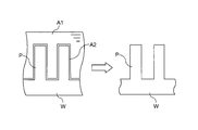
- step S6 using the irradiation unit 10 described above, the heating by the irradiation unit 10 causes the liquid A1 to vaporize from around the pattern P on the surface of the substrate W as shown in FIG. The surface will dry instantly.
- the irradiation unit 10 generates the gas layer A2 on the surface of the substrate W to which the liquid A1 is supplied so as to make the liquid A1 into a liquid ball (generates a liquid ball of the liquid A1). Only the substrate W is heated instantaneously.
- the liquid A1 in contact with the pattern P on the surface of the substrate W starts to vaporize earlier than the liquid A1 in other portions.
- a gas layer a collection of bubbles
- a gas layer A2 is generated like a thin film around the pattern P on the surface of the substrate W by vaporization (boiling) of the liquid A1.
- the liquid A1 between the adjacent patterns P is dried while being pushed out to the surface of the substrate W by the gas layer A2.
- the volatile solvent liquid A1 in contact with the pattern P on the surface of the substrate W is instantaneously vaporized, and the volatile solvent in other portions on the surface of the substrate W is obtained.
- the liquid A1 immediately turns into liquid balls (liquid ball formation phenomenon).
- the liquid balls thus generated are blown from the substrate W by the centrifugal force generated by the rotation of the substrate W, and as a result, the drying of the substrate W is completed. In this way, it is possible to suppress the liquid A1 from remaining between some patterns, and the drying speed of the liquid A1 on the surface of the substrate W becomes uniform. Therefore, the collapse force (for example, The pattern P can be prevented from collapsing due to surface tension or the like.
- the drying speed of the liquid A1 is uneven in the process of drying the IPA liquid A1, and as shown in FIG.
- the liquid A1 remains, and the pattern P collapses due to the collapse force of the liquid A1 in that portion.
- one width of the pattern P is 20 nm and its height is 200 nm (the height is 10 times the width).
- the pattern P is a fine pattern, and the liquid A1 entering the gap between the patterns P is difficult to dry. For this reason, even after the other portions are dried, the liquid A1 remains between some patterns P, and the pattern collapses due to the collapse force of the liquid A1.
- the substrate W supplied with the volatile solvent for example, IPA
- the volatile solvent for example, IPA
- vaporization condensation
- the surface of the substrate W can be instantly dried without leaving a volatile solvent between the patterns by the gas layer generated at this time.
- heating by irradiation of the irradiation unit 10 may be started during the supply of the volatile solvent.
- the drying time of the substrate W can be shortened as compared with the case where heating is started after the supply of the volatile solvent is completed, so that the entire processing time can be shortened.
- APM is used as the first processing liquid.
- SPM mixed liquid of sulfuric acid and hydrogen peroxide solution
- APM does not easily react with IPA, but SPM easily reacts with IPA.
- the supply of the volatile solvent such as IPA is started after the supply of the cleaning liquid to the substrate W is stopped.
- the supply of the volatile solvent may be started from when the processing liquid is supplied to the substrate W.
- the second embodiment is basically the same as the first embodiment. Therefore, in the second embodiment, differences from the first embodiment will be described, the same parts as those described in the first embodiment will be denoted by the same reference numerals, and the description thereof will also be omitted.
- a nozzle 8 a and a nozzle 9 a of the gas supply unit 9 are provided in the irradiation unit 10. These nozzles 6a, 7a, 8a and 9a are formed so as to be able to supply respective fluids (first processing liquid, second processing liquid, volatile solvent or gas) to the surface of the substrate W on the table 4. Yes.
- each nozzle 6a, 7a, 8a, and 9a the material which is not deform
- materials such as quartz which is not heated by each lamp
- the nozzles 6a, 7a, 8a, and 9a are located immediately above the substrate W on the table 4, so that even when the flow rate when supplying liquid or gas is low, The liquid or gas can be easily supplied to the center of the substrate. Further, since the surface of the substrate W can be coated with the liquid even if the flow rate of the supplied liquid is reduced, the amount of liquid used can be reduced. Similarly, even if the flow rate of the supplied gas is reduced, the space on the surface of the substrate W can be made the supplied gas atmosphere, so that the amount of gas used can be reduced.
- the same effect as that of the first embodiment can be obtained. Furthermore, by providing the nozzles 6a, 7a, 8a, and 9a in the irradiation unit 10, the liquid and the gas can be easily supplied to the center of the substrate even when the flow rate when supplying the liquid and the gas is low. In addition, the flow rate of the liquid or gas can be reduced, and the amount of the liquid or gas used can be reduced.
- the third embodiment is basically the same as the second embodiment. Therefore, in the third embodiment, differences from the second embodiment will be described, the same parts as those described in the second embodiment will be denoted by the same reference numerals, and the description thereof will also be omitted.
- the irradiation unit 10 is located below the substrate W, that is, between the substrate W and the table 4 on each support member 4a. It is provided to irradiate light onto the surface of the substrate W on the table 4 side. As in the second embodiment, the irradiation unit 10 can be moved in the ascending / descending direction (vertical direction) by the moving mechanism 11.
- the irradiation unit 10 is located between the substrate W on each support member 4a and the table 4, a space above the substrate W on each support member 4a is formed. It is possible to open the space, and other members and devices (for example, the nozzles 6a, 7a, 8a, and 9a) can be easily provided in the space without having a complicated structure.
- the same effect as that of the second embodiment can be obtained. Further, by providing the irradiation unit 10 below the substrate W on each support member 4a, for example, between the substrate W on each support member 4a and the table 4, a space above the substrate W on each support member 4a is provided. Since it becomes possible to open, other members or devices can be easily installed in the space.
- the fourth embodiment is basically the same as the first embodiment. For this reason, in the fourth embodiment, differences from the first embodiment will be described, the same parts as those described in the first embodiment will be denoted by the same reference numerals, and description thereof will also be omitted.
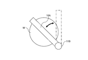
- the irradiation unit 10A is a line laser that emits line laser light.
- the irradiation unit 10 ⁇ / b> A has a length in the longitudinal direction longer than the diameter of the substrate W, and is configured to be movable along the surface of the substrate W on the table 4 by the moving mechanism 11 ⁇ / b> A.
- the irradiation unit 10A heats the substrate W so as to generate a gas layer (gas layer) on the surface of the substrate W supplied with the volatile solvent.
- the moving mechanism 11A includes a pair of moving mechanisms 21 and 22 (see FIG. 8) that hold and move the irradiation unit 10A, a support 23 that supports the moving mechanism 21, and a support 24 that supports the moving mechanism 22 (see FIG. 8). ).
- the pair of moving mechanisms 21 and 22 hold the irradiation unit 10A so that the irradiation unit 10A is positioned above the substrate W on the table 4, and move in parallel along the surface of the substrate W on the table 4.
- these moving mechanisms 21 and 22 for example, a feed screw type moving mechanism using a servo motor as a driving source, a linear motor type moving mechanism using a linear motor as a driving source, or the like can be used.
- the irradiation unit 10A uses a pair of moving mechanisms 21 and 22 in parallel along the surface of the substrate W on the rotating table 4 when performing heat drying.
- the irradiation unit 10A moves from the center of the substrate W to the outer periphery, for example.
- a gas layer gas layer
- the surface of the substrate W is instantaneously dried. It will be.
- the irradiation unit 10A is provided on the upper part of the moving mechanism 11B that functions as a support, and the moving mechanism 11B uses the axis of the moving mechanism 11B that is the support as a rotation axis along the surface of the substrate W. It is configured to be swingable (rotatable).
- the irradiation unit 10A is rotated about the rotation axis by the moving mechanism 11B, and irradiates the laser beam while moving (swinging) in parallel along the surface of the substrate W on the rotating table 4.
- the entire surface of the substrate W is irradiated with laser light.
- the same effect as that of the first embodiment can be obtained. Further, by using the line laser type irradiation unit 10A, it is possible to prevent the irradiation apparatus from becoming larger than the irradiation unit that covers the entire surface of the substrate W on the table 4.
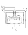
- the fifth embodiment is basically the same as the first embodiment. Therefore, in the fifth embodiment, differences from the first embodiment will be described, the same parts as those described in the first embodiment will be denoted by the same reference numerals, and the description thereof will also be omitted.
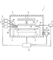
- a decompression unit 31 for decompressing the inside of the processing box 2 is provided.
- the decompression unit 31 includes a pipe 31a connected to the processing box 2, and a decompression pump 31b provided in the middle of the pipe 31a.
- the decompression pump 31 b is electrically connected to the control unit 12, and its driving is controlled by the control unit 12.
- Such a decompression part 31 exhausts the gas in the processing box 2 from the piping 31a by driving the decompression pump 31b, decompresses the inside of the processing box 2, and puts it in a vacuum state.
- the inside of the processing box 2 is decompressed to a predetermined vacuum pressure by the decompression unit 31.
- heat drying by the irradiation unit 10 is executed (step S6 in FIG. 2 in the first embodiment).
- the boiling point of IPA is lowered due to the reduced pressure in the processing box 2, and the above-described liquid ball formation phenomenon can be caused at a heating temperature lower than that in the atmosphere as the boiling point is lowered. For this reason, heating drying can be performed even when the substrate W to be handled is not suitable for high-temperature heating.
- the same effect as that of the first embodiment can be obtained. Further, by performing heat drying by the irradiation unit 10 with the inside of the processing box 2 in a reduced pressure state, the boiling point of the liquid existing on the surface of the substrate W in the processing box 2 is lowered, and the boiling point is lowered, so that it is lower than in the atmosphere. It becomes possible to cause a liquid ball formation phenomenon at a low heating temperature. For this reason, even when the substrate W to be handled is not suitable for high-temperature heating as compared with the case where the drying by the irradiation unit 10 is performed without reducing the inside of the processing box 2, the drying is performed at a lower heating temperature than in the atmosphere. It is possible to perform good substrate drying while reliably suppressing pattern collapse.
- the sixth embodiment is basically the same as the first embodiment. Therefore, in the sixth embodiment, differences from the first embodiment will be described, the same parts as those described in the first embodiment will be denoted by the same reference numerals, and the description thereof will also be omitted.
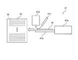
- a transport unit 41 for transporting the substrate W is provided.
- the transport unit 41 unloads the substrate W from the table 4 in the processing box 2 and transports the substrate W to a buffer unit 42 that accommodates a large number of substrates W.
- the substrate processing apparatus 1 according to the sixth embodiment does not include the irradiation unit 10 according to the first embodiment, and in the substrate processing step according to the sixth embodiment, heat drying by the irradiation unit 10 is not performed. Without being executed, the swing-off drying is performed by the rotation of the substrate W.
- the transport unit 41 includes a transport arm 41 a that can transport the substrate W between the processing box 2 and the buffer unit 42, a transport arm heater 41 b that is attached to the transport arm 41 a and supports the substrate W, and a transport arm.
- a gas blowing part 41c for blowing a gas (for example, an inert gas such as nitrogen gas) toward the substrate W on the heater 41b and an exhaust part 41d for sucking and exhausting the gas returning from the substrate W are provided. .
- the transfer arm heater 41b heats the substrate W instantaneously to a high temperature during the transfer of the substrate W, supports the substrate W, and functions as a heating unit that heats the supporting substrate W. As in the first embodiment, the transfer arm heater 41b heats the substrate W so as to generate a gas layer (gas layer) on the surface of the substrate W supplied with the volatile solvent. Since the substrate W taken out from the processing box 2 is only shaken and dried in the processing box 2, it is placed on the transport arm heater 41b in a state where the volatile solvent is not completely dried (a state where the volatile solvent is attached to some extent). Will be placed.
- the gas blowing section 41c and the exhaust section 41d are provided along the transport path of the substrate W from the processing box 2 to the buffer section 42 (transport path of the substrate W by the transport arm 41a).
- the gas blowing part 41c is positioned upstream of the exhaust part 41d in the transport direction of the substrate W. Therefore, the exhaust part 41d is located on the downstream side of the gas blowing part 41c and is installed so as to suck in the gas blown out from the gas blowing part 41 and hitting the surface of the substrate W.
- the gas spraying part 41c blows and removes the liquid balls of the volatile solvent generated on the surface of the substrate W by the heating of the transport arm heater 41b, and is located above the transport path of the substrate W. It is provided so as to be inclined with respect to the surface of the substrate W on the arm heater 41b.
- the gas blowing part 41c blows out gas from a slit-like opening (not shown) having a width substantially equal to or larger than the substrate width in the direction perpendicular to the transport direction of the substrate W.
- the exhaust part 41d sucks the liquid balls blown off by the gas spraying part 41c so as not to be scattered in the transport path, and is positioned above the transport path of the substrate W, and the transport arm heater 41b. It is provided so as to be perpendicular to the surface of the upper substrate W.
- the exhaust part 41d sucks gas from a slit-like opening (not shown) having an opening width that is substantially the same as or larger than the substrate width in the direction perpendicular to the transport direction of the substrate W.
- the substrate W taken out from the processing box 2 is placed on the transport arm heater 41b in the heater-off state.
- the transfer arm 41a moves from right to left in FIG.
- the heater is turned on when the transfer arm heater 41b approaches the gas blowing part 41c, and the substrate W is rapidly heated by turning on the heater.
- a liquid ball of a volatile solvent is generated on the surface of the substrate W.
- the liquid ball of the volatile solvent generated on the surface of the substrate W is blown off from the surface of the substrate W by the gas from the gas spraying part 41c, and is sucked and removed by the exhaust part 41d.
- the surface of the substrate W is instantly dried. Note that when the substrate W is heated, the substrate W is transported in one direction and does not rotate.
- the same effect as that of the first embodiment can be obtained. Furthermore, by performing heat drying by the transfer arm heater 41b during the transfer of the substrate W, it is possible to perform good substrate drying while suppressing pattern collapse without performing heat drying in the processing box 2. Become. For this reason, heating and drying in the processing box 2 can be omitted, and the substrate processing time in the processing box 2 can be shortened.
- the gas blowing part 41c and the exhaust part 41d are provided above the transport path of the substrate W (so as to be positioned above the substrate W).
- the gas blowing part 41c may be provided beside the transport path of the substrate W, and the exhaust part 41d may be provided on the opposite side. In this case, gas is blown from the side to the surface of the substrate W on the transfer arm heater 41b, and the gas is sucked from the opposite side.
- the liquid ball of the volatile solvent generated on the surface of the substrate W by the rapid heating by the transfer arm heater 41b may be removed from the surface of the substrate W by tilting the substrate W. This is because the substrate W is rapidly heated by the transfer arm heater 41b during the transfer of the substrate W, and then the transfer arm 41a is rotated around an axis along the transfer direction, for example. This can be done by inclining. By tilting the substrate W, the liquid balls of the volatile solvent are removed from the surface of the substrate W so as to slide on the surface of the substrate W.
Abstract
Description
第1の実施形態について図1ないし図4を参照して説明する。
第2の実施形態について図5を参照して説明する。
第3の実施形態について図6を参照して説明する。
第4の実施形態について図7ないし図9を参照して説明する。
第5の実施形態について図10を参照して説明する。
第6の実施形態について図11を参照して説明する。
Claims (12)
- 基板の表面に揮発性溶媒を供給する溶媒供給部と、
前記揮発性溶媒が供給された前記基板の表面に気層を生じさせて前記揮発性溶媒を液玉化させるように前記基板を加熱する加熱部と、
を備えることを特徴とする基板処理装置。 - 前記加熱部を前記基板の表面に対して上下方向に移動させる移動機構をさらに備えることを特徴とする請求項1に記載の基板処理装置。
- 前記加熱部を前記基板の表面に沿って移動させる移動機構をさらに備えることを特徴とする請求項1に記載の基板処理装置。
- 前記加熱部は、前記揮発性溶媒が供給された前記基板に対して電磁波を照射する照射部であることを特徴とする請求項1に記載の基板処理装置。
- 前記溶媒供給部による前記揮発性溶媒の供給中に、前記加熱部に前記基板に対する加熱を実行させる制御部をさらに備えることを特徴とする請求項1に記載の基板処理装置。
- 前記溶媒供給部による前記揮発性溶媒の供給後に、前記加熱部に前記基板に対する加熱を実行させる制御部をさらに備えることを特徴とする請求項1に記載の基板処理装置。
- 前記基板を平面内で回転させる回転機構と、
前記回転機構による前記基板の回転中に、前記溶媒供給部に前記揮発性溶媒の供給を実行させ、前記加熱部に前記基板に対する加熱を実行させる制御部と、
をさらに備えることを特徴とする請求項1に記載の基板処理装置。 - 基板の表面に揮発性溶媒を供給する工程と、
前記揮発性溶媒が供給された前記基板の表面に気層を生じさせて前記揮発性溶媒を液玉化させるように前記基板を加熱する工程と、
を有することを特徴とする基板処理方法。 - 前記基板を加熱する工程では、前記揮発性溶媒が供給された前記基板に対して電磁波を照射することを特徴とする請求項8に記載の基板処理方法。
- 前記基板を加熱する工程では、前記揮発性溶媒の供給中に、前記基板を加熱することを特徴とする請求項8に記載の基板処理方法。
- 前記基板を加熱する工程では、前記揮発性溶媒の供給後に、前記基板を加熱することを特徴とする請求項8に記載の基板処理方法。
- 前記揮発性溶媒を供給する工程では、前記基板を平面内で回転させながら前記基板の表面に前記揮発性溶媒を供給し、
前記基板を加熱する工程では、前記基板を平面内で回転させながら前記基板を加熱することを特徴とする請求項8に記載の基板処理方法。
Priority Applications (4)
| Application Number | Priority Date | Filing Date | Title |
|---|---|---|---|
| EP14760514.1A EP2966673B1 (en) | 2013-03-07 | 2014-02-28 | Substrate processing device and substrate processing method |
| KR1020157025984A KR101759414B1 (ko) | 2013-03-07 | 2014-02-28 | 기판 처리 장치 및 기판 처리 방법 |
| US14/773,055 US10281210B2 (en) | 2013-03-07 | 2014-02-28 | Substrate processing apparatus and substrate processing method |
| CN201480010842.3A CN105027268B (zh) | 2013-03-07 | 2014-02-28 | 基板处理装置以及基板处理方法 |
Applications Claiming Priority (6)
| Application Number | Priority Date | Filing Date | Title |
|---|---|---|---|
| JP2013045532 | 2013-03-07 | ||
| JP2013-045532 | 2013-03-07 | ||
| JP2013-140416 | 2013-07-04 | ||
| JP2013140416 | 2013-07-04 | ||
| JP2014028314A JP6400919B2 (ja) | 2013-03-07 | 2014-02-18 | 基板処理装置及び基板処理方法 |
| JP2014-028314 | 2014-02-18 |
Publications (1)
| Publication Number | Publication Date |
|---|---|
| WO2014136670A1 true WO2014136670A1 (ja) | 2014-09-12 |
Family
ID=51491189
Family Applications (1)
| Application Number | Title | Priority Date | Filing Date |
|---|---|---|---|
| PCT/JP2014/055054 WO2014136670A1 (ja) | 2013-03-07 | 2014-02-28 | 基板処理装置及び基板処理方法 |
Country Status (7)
| Country | Link |
|---|---|
| US (1) | US10281210B2 (ja) |
| EP (1) | EP2966673B1 (ja) |
| JP (1) | JP6400919B2 (ja) |
| KR (1) | KR101759414B1 (ja) |
| CN (1) | CN105027268B (ja) |
| TW (1) | TWI590318B (ja) |
| WO (1) | WO2014136670A1 (ja) |
Cited By (2)
| Publication number | Priority date | Publication date | Assignee | Title |
|---|---|---|---|---|
| WO2017169435A1 (ja) * | 2016-03-30 | 2017-10-05 | 株式会社Screenホールディングス | 基板処理装置 |
| WO2024047955A1 (ja) * | 2022-08-31 | 2024-03-07 | 株式会社Screenホールディングス | 基板処理方法および基板処理装置 |
Families Citing this family (32)
| Publication number | Priority date | Publication date | Assignee | Title |
|---|---|---|---|---|
| JP6131162B2 (ja) | 2012-11-08 | 2017-05-17 | 株式会社Screenホールディングス | 基板処理方法および基板処理装置 |
| JP6317837B2 (ja) * | 2012-11-08 | 2018-04-25 | 株式会社Screenホールディングス | 基板処理方法および基板処理装置 |
| JP6286024B2 (ja) * | 2014-03-07 | 2018-02-28 | 富士フイルム株式会社 | トランジスタの製造方法 |
| JP6304592B2 (ja) * | 2014-03-25 | 2018-04-04 | 株式会社Screenホールディングス | 基板処理方法および基板処理装置 |
| KR101877112B1 (ko) * | 2015-01-23 | 2018-07-10 | 가부시키가이샤 스크린 홀딩스 | 기판 처리 방법 및 기판 처리 장치 그리고 유체 노즐 |
| JP6687436B2 (ja) * | 2015-04-30 | 2020-04-22 | 芝浦メカトロニクス株式会社 | 基板処理装置及び基板処理方法 |
| KR101860631B1 (ko) | 2015-04-30 | 2018-05-23 | 시바우라 메카트로닉스 가부시끼가이샤 | 기판 처리 장치 및 기판 처리 방법 |
| JP6418554B2 (ja) * | 2015-06-10 | 2018-11-07 | 株式会社Screenホールディングス | 基板処理方法および基板処理装置 |
| JP6742708B2 (ja) * | 2015-09-29 | 2020-08-19 | 芝浦メカトロニクス株式会社 | 基板処理方法 |
| CN107123610B (zh) * | 2016-02-25 | 2021-08-06 | 芝浦机械电子株式会社 | 基板处理装置、基板处理方法及基板的制造方法 |
| JP6722551B2 (ja) | 2016-08-31 | 2020-07-15 | 株式会社Screenホールディングス | 基板処理方法 |
| JP6728009B2 (ja) * | 2016-09-26 | 2020-07-22 | 株式会社Screenホールディングス | 基板処理方法および基板処理装置 |
| KR102030068B1 (ko) * | 2017-10-12 | 2019-10-08 | 세메스 주식회사 | 기판 처리 장치 및 기판 처리 방법 |
| KR102249802B1 (ko) * | 2018-07-13 | 2021-05-10 | 세메스 주식회사 | 기판 처리 장치 |
| JP7175119B2 (ja) * | 2018-07-25 | 2022-11-18 | 東京エレクトロン株式会社 | 基板処理装置、および基板処理方法 |
| JP7077184B2 (ja) * | 2018-08-30 | 2022-05-30 | キオクシア株式会社 | 基板処理方法及び半導体装置の製造方法 |
| JP7336306B2 (ja) * | 2018-10-23 | 2023-08-31 | 東京エレクトロン株式会社 | 基板処理装置、基板処理方法および記憶媒体 |
| CN109489363A (zh) * | 2018-12-24 | 2019-03-19 | 国兴(东莞)新能源科技有限公司 | 一种软包电池除水装置 |
| CN111380331A (zh) * | 2018-12-29 | 2020-07-07 | 中国科学院微电子研究所 | 一种微波干燥装置 |
| JP7194645B2 (ja) * | 2019-05-31 | 2022-12-22 | 株式会社Screenホールディングス | 基板処理方法および基板処理装置 |
| CN110631342A (zh) * | 2019-10-15 | 2019-12-31 | 东海县牡丹手套有限公司 | 一种手套加工用手套存放设备 |
| KR102391973B1 (ko) * | 2019-10-21 | 2022-04-27 | 세메스 주식회사 | 기판 처리 장치 |
| JP7406404B2 (ja) | 2020-02-28 | 2023-12-27 | 株式会社Screenホールディングス | 基板処理方法および基板処理装置 |
| JP6886546B2 (ja) * | 2020-05-12 | 2021-06-16 | 芝浦メカトロニクス株式会社 | 基板処理装置 |
| TWI793744B (zh) * | 2020-09-09 | 2023-02-21 | 日商國際電氣股份有限公司 | 基板處理裝置、半導體裝置之製造方法及程式 |
| CN112503894A (zh) * | 2020-12-07 | 2021-03-16 | 安徽海洋药业有限公司 | 一种药瓶干燥机 |
| CN114674120A (zh) * | 2020-12-24 | 2022-06-28 | 中国科学院微电子研究所 | 半导体干燥装置及方法 |
| CN112856981A (zh) * | 2021-01-13 | 2021-05-28 | 东莞理工学院 | 一种用于mems器件圆片的自动干燥设备 |
| CN112902616A (zh) * | 2021-01-22 | 2021-06-04 | 徐州中辉光伏科技有限公司 | 一种高效率的太阳能光伏板组件加工用烘干装置 |
| CN112944856B (zh) * | 2021-04-18 | 2022-08-16 | 黄韶平 | 试剂盒烘干装置 |
| CN112944831A (zh) * | 2021-04-23 | 2021-06-11 | 江西省优斯特能源有限公司 | 一种具有转动结构的电池加工用烘干设备 |
| CN116147309B (zh) * | 2023-02-21 | 2023-09-22 | 闽海家居(江苏)有限公司 | 一种木地板生产原木干燥装置及其干燥方法 |
Citations (5)
| Publication number | Priority date | Publication date | Assignee | Title |
|---|---|---|---|---|
| JPH10199855A (ja) * | 1996-10-01 | 1998-07-31 | Sez Semiconductor Equip Zubehoer Fuer Die Halbleiterfertigung Gmbh | 基板の乾燥方法及び装置 |
| JP2002305178A (ja) * | 2001-04-09 | 2002-10-18 | Ekoo Giken Kk | ウエハの乾燥装置および乾燥方法 |
| JP2008034779A (ja) | 2006-06-27 | 2008-02-14 | Dainippon Screen Mfg Co Ltd | 基板処理方法および基板処理装置 |
| JP2010238918A (ja) * | 2009-03-31 | 2010-10-21 | Dainippon Screen Mfg Co Ltd | 基板処理装置及び基板処理方法 |
| JP2012138510A (ja) * | 2010-12-27 | 2012-07-19 | Tokyo Electron Ltd | 液処理装置、液処理方法及びその液処理方法を実行させるためのプログラムを記録した記録媒体 |
Family Cites Families (14)
| Publication number | Priority date | Publication date | Assignee | Title |
|---|---|---|---|---|
| JP3402932B2 (ja) * | 1995-05-23 | 2003-05-06 | 東京エレクトロン株式会社 | 洗浄方法及びその装置 |
| TW386235B (en) | 1995-05-23 | 2000-04-01 | Tokyo Electron Ltd | Method for spin rinsing |
| US6248168B1 (en) * | 1997-12-15 | 2001-06-19 | Tokyo Electron Limited | Spin coating apparatus including aging unit and solvent replacement unit |
| JP4333866B2 (ja) * | 2002-09-26 | 2009-09-16 | 大日本スクリーン製造株式会社 | 基板処理方法および基板処理装置 |
| US7708751B2 (en) * | 2004-05-21 | 2010-05-04 | Ethicon Endo-Surgery, Inc. | MRI biopsy device |
| US20070029536A1 (en) * | 2005-08-04 | 2007-02-08 | Garvin Goode | Picket assembly |
| JP2008034428A (ja) * | 2006-07-26 | 2008-02-14 | Dainippon Screen Mfg Co Ltd | 基板処理装置および基板処理方法 |
| US7838425B2 (en) * | 2008-06-16 | 2010-11-23 | Kabushiki Kaisha Toshiba | Method of treating surface of semiconductor substrate |
| JP5413016B2 (ja) * | 2008-07-31 | 2014-02-12 | 東京エレクトロン株式会社 | 基板の洗浄方法、基板の洗浄装置及び記憶媒体 |
| US8153533B2 (en) * | 2008-09-24 | 2012-04-10 | Lam Research | Methods and systems for preventing feature collapse during microelectronic topography fabrication |
| JP5359286B2 (ja) * | 2009-01-07 | 2013-12-04 | 東京エレクトロン株式会社 | 超臨界処理装置、基板処理システム及び超臨界処理方法 |
| US20120016027A1 (en) * | 2010-07-15 | 2012-01-19 | Brien Holden Vision Institute | Composition and Method for Improved Lens Comfort |
| US20120103371A1 (en) * | 2010-10-28 | 2012-05-03 | Lam Research Ag | Method and apparatus for drying a semiconductor wafer |
| JP5611884B2 (ja) * | 2011-04-14 | 2014-10-22 | 東京エレクトロン株式会社 | エッチング方法、エッチング装置および記憶媒体 |
-
2014
- 2014-02-18 JP JP2014028314A patent/JP6400919B2/ja active Active
- 2014-02-28 EP EP14760514.1A patent/EP2966673B1/en active Active
- 2014-02-28 CN CN201480010842.3A patent/CN105027268B/zh active Active
- 2014-02-28 US US14/773,055 patent/US10281210B2/en active Active
- 2014-02-28 WO PCT/JP2014/055054 patent/WO2014136670A1/ja active Application Filing
- 2014-02-28 KR KR1020157025984A patent/KR101759414B1/ko active IP Right Grant
- 2014-03-06 TW TW103107697A patent/TWI590318B/zh active
Patent Citations (5)
| Publication number | Priority date | Publication date | Assignee | Title |
|---|---|---|---|---|
| JPH10199855A (ja) * | 1996-10-01 | 1998-07-31 | Sez Semiconductor Equip Zubehoer Fuer Die Halbleiterfertigung Gmbh | 基板の乾燥方法及び装置 |
| JP2002305178A (ja) * | 2001-04-09 | 2002-10-18 | Ekoo Giken Kk | ウエハの乾燥装置および乾燥方法 |
| JP2008034779A (ja) | 2006-06-27 | 2008-02-14 | Dainippon Screen Mfg Co Ltd | 基板処理方法および基板処理装置 |
| JP2010238918A (ja) * | 2009-03-31 | 2010-10-21 | Dainippon Screen Mfg Co Ltd | 基板処理装置及び基板処理方法 |
| JP2012138510A (ja) * | 2010-12-27 | 2012-07-19 | Tokyo Electron Ltd | 液処理装置、液処理方法及びその液処理方法を実行させるためのプログラムを記録した記録媒体 |
Cited By (3)
| Publication number | Priority date | Publication date | Assignee | Title |
|---|---|---|---|---|
| WO2017169435A1 (ja) * | 2016-03-30 | 2017-10-05 | 株式会社Screenホールディングス | 基板処理装置 |
| US10593587B2 (en) | 2016-03-30 | 2020-03-17 | SCREEN Holdings Co., Ltd. | Substrate treatment apparatus |
| WO2024047955A1 (ja) * | 2022-08-31 | 2024-03-07 | 株式会社Screenホールディングス | 基板処理方法および基板処理装置 |
Also Published As
| Publication number | Publication date |
|---|---|
| EP2966673A1 (en) | 2016-01-13 |
| CN105027268A (zh) | 2015-11-04 |
| KR20150120506A (ko) | 2015-10-27 |
| US10281210B2 (en) | 2019-05-07 |
| JP2015029041A (ja) | 2015-02-12 |
| JP6400919B2 (ja) | 2018-10-03 |
| TWI590318B (zh) | 2017-07-01 |
| EP2966673B1 (en) | 2020-10-14 |
| US20160025409A1 (en) | 2016-01-28 |
| TW201508830A (zh) | 2015-03-01 |
| KR101759414B1 (ko) | 2017-07-18 |
| CN105027268B (zh) | 2017-07-11 |
| EP2966673A4 (en) | 2016-11-09 |
Similar Documents
| Publication | Publication Date | Title |
|---|---|---|
| JP6400919B2 (ja) | 基板処理装置及び基板処理方法 | |
| KR101688689B1 (ko) | 기판 처리 장치 및 기판 처리 방법 | |
| JP6351993B2 (ja) | 基板処理装置及び基板処理方法 | |
| JP6426927B2 (ja) | 基板処理装置及び基板処理方法 | |
| JP6426924B2 (ja) | 基板処理装置及び基板処理方法 | |
| JP2008128567A (ja) | 基板乾燥方法および基板乾燥装置 | |
| JP2015092539A (ja) | 基板処理装置及び基板処理方法 | |
| JP6276924B2 (ja) | 基板処理装置 | |
| JP6302700B2 (ja) | 基板処理装置及び基板処理方法 | |
| JP6585243B2 (ja) | 基板処理装置及び基板処理方法 |
Legal Events
| Date | Code | Title | Description |
|---|---|---|---|
| WWE | Wipo information: entry into national phase |
Ref document number: 201480010842.3 Country of ref document: CN |
|
| 121 | Ep: the epo has been informed by wipo that ep was designated in this application |
Ref document number: 14760514 Country of ref document: EP Kind code of ref document: A1 |
|
| WWE | Wipo information: entry into national phase |
Ref document number: 14773055 Country of ref document: US |
|
| NENP | Non-entry into the national phase |
Ref country code: DE |
|
| WWE | Wipo information: entry into national phase |
Ref document number: 2014760514 Country of ref document: EP |
|
| ENP | Entry into the national phase |
Ref document number: 20157025984 Country of ref document: KR Kind code of ref document: A |