WO2014136669A1 - X線診断装置 - Google Patents
X線診断装置 Download PDFInfo
- Publication number
- WO2014136669A1 WO2014136669A1 PCT/JP2014/055050 JP2014055050W WO2014136669A1 WO 2014136669 A1 WO2014136669 A1 WO 2014136669A1 JP 2014055050 W JP2014055050 W JP 2014055050W WO 2014136669 A1 WO2014136669 A1 WO 2014136669A1
- Authority
- WO
- WIPO (PCT)
- Prior art keywords
- posture
- unit
- ray
- diagnostic apparatus
- angle
- Prior art date
Links
Images


Classifications
-
- A—HUMAN NECESSITIES
- A61—MEDICAL OR VETERINARY SCIENCE; HYGIENE
- A61B—DIAGNOSIS; SURGERY; IDENTIFICATION
- A61B6/00—Apparatus for radiation diagnosis, e.g. combined with radiation therapy equipment
- A61B6/54—Control of apparatus or devices for radiation diagnosis
- A61B6/547—Control of apparatus or devices for radiation diagnosis involving tracking of position of the device or parts of the device
-
- A—HUMAN NECESSITIES
- A61—MEDICAL OR VETERINARY SCIENCE; HYGIENE
- A61B—DIAGNOSIS; SURGERY; IDENTIFICATION
- A61B6/00—Apparatus for radiation diagnosis, e.g. combined with radiation therapy equipment
- A61B6/44—Constructional features of apparatus for radiation diagnosis
- A61B6/4429—Constructional features of apparatus for radiation diagnosis related to the mounting of source units and detector units
- A61B6/4435—Constructional features of apparatus for radiation diagnosis related to the mounting of source units and detector units the source unit and the detector unit being coupled by a rigid structure
- A61B6/4441—Constructional features of apparatus for radiation diagnosis related to the mounting of source units and detector units the source unit and the detector unit being coupled by a rigid structure the rigid structure being a C-arm or U-arm
-
- A—HUMAN NECESSITIES
- A61—MEDICAL OR VETERINARY SCIENCE; HYGIENE
- A61B—DIAGNOSIS; SURGERY; IDENTIFICATION
- A61B6/00—Apparatus for radiation diagnosis, e.g. combined with radiation therapy equipment
- A61B6/04—Positioning of patients; Tiltable beds or the like
- A61B6/0407—Supports, e.g. tables or beds, for the body or parts of the body
Definitions
- Embodiment relates to an X-ray diagnostic apparatus.
- an operation of moving a supporter such as a C-arm may be required. This operation is performed by manual input by the user using the operation unit.
- Patent Document 2 when performing an inspection in which the observation direction is determined in advance, such as a routine inspection, by registering the inspection sequence in advance, switching of an imaging program at the time of actual inspection or auto-positioning Has been disclosed.
- This function is called a sequence automatic reproduction function.
- Patent Document 3 discloses a technique for displaying a list of shooting angles stored in the auto-positioning function on a monitor when reproducing the shooting angles by auto-positioning.
- the above-described auto-positioning requires a user to input a positioning number and select from a number of angle candidates.
- the positioning number is a number associated with each registered position.
- the supporter or the bed is positioned at a desired position (that is, the desired position is reproduced).
- the user clearly recognizes the posture (angle) of the supporter or bed that he / she wants to reproduce, but does not always remember the positioning number associated with the posture.
- An object of the embodiment is to provide an X-ray diagnostic apparatus that can execute positioning of a supporter by an intuitive operation.
- An X-ray diagnostic apparatus includes an X-ray tube that generates X-rays, an X-ray detector that detects X-rays generated by the X-ray tube, and the X-ray tube and the X-ray detector. And a support portion that rotatably supports the plurality of movable shafts, and angle information expressed by rotation angles about the plurality of movable shafts regarding at least one preset posture of the support portion.
- a storage unit and a display unit for displaying at least one first angle mark corresponding to the at least one posture on a clinical angle map expressing the coordinate system based on the plurality of movable axes defining the posture of the support unit And.
- FIG. 1 is a block diagram illustrating a configuration example of the X-ray diagnostic apparatus according to the first embodiment.
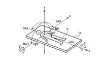
- FIG. 2 is a diagram illustrating an example of a coordinate system related to driving of the support.
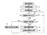
- FIG. 3 is a diagram illustrating a flowchart of a clinical angle setting process performed by the X-ray diagnostic apparatus according to the first embodiment.
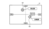
- FIG. 4 is a diagram illustrating an example of a clinical angle map presented to the user during the clinical angle setting process.
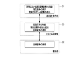
- FIG. 5 is a block diagram illustrating a cooperative relationship among the system control unit, the display unit / operation unit, and the drive unit.
- FIG. 6 is a diagram showing another example of the clinical angle map.
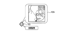
- FIG. 7 is a diagram illustrating a display example of auxiliary information displayed together with the target posture mark.
- FIG. 8 is a diagram illustrating a display example of auxiliary information displayed together with the target posture mark.
- FIG. 9 is a diagram illustrating an example of a clinical angle map presented to the user during the clinical angle setting process.
- FIG. 10 is a block diagram illustrating a cooperative relationship among the system control unit, the display unit / operation unit, and the drive unit.
- FIG. 11 is a diagram illustrating a display example of auxiliary information displayed together with the target posture mark.
- FIG. 12 is a diagram illustrating an example of a clinical angle map presented to the user during the clinical angle setting process.
- FIG. 13 is a diagram illustrating an example of a clinical angle map presented to the user during the clinical angle setting process.
- FIG. 14 is a diagram illustrating a display example of a schematic image according to the fourth embodiment.
- FIG. 1 is a block diagram illustrating a configuration example of the X-ray diagnostic apparatus according to the first embodiment.
- the X-ray diagnostic apparatus 1 includes a support 10, a bed 11, an X-ray irradiation unit 14, an X-ray detector 15, an image data generation unit 18, an operation unit 21, and an image.
- a storage unit 22, a system control unit 23, a display unit 27, an X-ray control unit 30, a high voltage supply device 31, and a drive unit 32 are provided.
- the support device 10 is a mechanism that supports the X-ray irradiation unit 14 and the X-ray detector 15 so as to be rotatable with respect to a plurality of movable shafts.
- the support device 10 includes a C-arm 10-1 and a base 10-2.
- the C-arm 10-1 supports the X-ray irradiation unit 14 and the X-ray detector 15 so as to be rotatable around the rotation axis.
- the base 10-2 supports the C-arm 10-1 so as to be rotatable about a rotation axis.
- the intersection of the rotation axis and the rotation axis is called an isocenter.
- the movable shaft is a shaft that conceptually includes a rotation shaft and a rotation shaft.
- the bed 11 is supported in the vertical direction and the horizontal direction. A subject P is placed on the bed 11.
- the X-ray irradiation unit 14 includes an X-ray tube 14-1 and an X-ray restrictor 14-2.
- the X-ray tube 14-1 is connected to the high voltage generator 31-1.
- the X-ray tube 14-1 receives the supply of the filament current from the high voltage generator 31-1 and the application of the high voltage, and generates X-rays.
- the X-ray restrictor 14-2 is attached to the X-ray tube 14-1.
- the X-ray diaphragm 14-2 limits the X-ray irradiation field irradiated to the subject P.
- the X-ray detector 15 detects X-rays generated by the X-ray tube 14-1 and transmitted through the subject P.
- FIG. 2 is a diagram illustrating an example of a coordinate system related to driving of the support 10.
- the axis parallel to the major axis of the bed 11 is taken as the z axis
- the axis parallel to the minor axis of the bed 11 is taken as the x axis
- the axis orthogonal to the upper surface of the bed 11 is taken as the y axis.
- the x-axis, y-axis, and z-axis constitute an orthogonal coordinate system.
- the axis connecting the focal point of the X-ray tube 14-1 and the center of the detection surface of the X-ray detector 15 is referred to as an imaging center axis.
- the inclination with respect to the x-axis of the photographing central axis is defined by the rotation angle ⁇
- the rotation angle ⁇ is defined as a reference angle, for example, the rotation angle ⁇ and the rotation angle ⁇ are 0 degrees.
- the tilt direction of the imaging center axis in the + x-axis direction is defined as LAO (Left Anterior Oblique View: second oblique position), and the tilt in the -x-axis direction is RAO (Right Anterior Oblique View: second view). 1 oblique direction).
- the direction of inclination of the imaging center axis in the ⁇ z-axis direction is defined as CRA (Cranial view)
- the direction of inclination in the + z-axis direction is CAU (Caudal view: head-to-tail direction).
- the image data generation unit 18 includes an arithmetic circuit 18-1 and a storage circuit 18-2.
- the arithmetic circuit 18-1 reads data in units of lines from the X-ray detector 15, and generates image data such as fluoroscopic image data and captured image data based on the read data. Further, the arithmetic circuit 18-1 associates the image capturing condition supplied from the system control unit 23 with the generated image data.
- Examples of the imaging conditions include the posture of the support 10 at the time of X-ray imaging. Specifically, the attitude of the supporter 10 means the orientation of the C-arm 10-1 in the xyz coordinate system. In other words, the posture of the supporter 10 means the relative orientation of the C arm 10-1 with respect to the bed 11.
- the storage circuit 18-2 stores the image data generated by the arithmetic circuit 18-1.
- the operation unit 21 is connected to the system control unit 23 and receives input of various operations on the X-ray diagnostic apparatus 1.
- the operation unit 21 is a touch panel, a control panel, a foot switch, a joystick, or the like.
- An example of the operation unit 21 according to the first embodiment is a touch panel. That is, in the first embodiment, it is assumed that a touch panel is used as an input / output device.
- the image storage unit 22 is a storage device that stores X-ray image data and the like. More specifically, the image storage unit 22 stores the X-ray image data in association with information indicating the posture of the supporter 10 when X-ray imaging of the X-ray image data is performed.
- information indicating the posture is referred to as posture information.
- the posture information is defined by the rotation angle of the support device 10.
- the system control unit 23 comprehensively controls each unit of the X-ray diagnostic apparatus 1.
- the display unit 27 displays various information. Specifically, the display unit 27 includes a display image data generation circuit 27-1 and a monitor 27-2.
- the display image data generation circuit 27-1 converts the image data generated by the X-ray detector 15 into display image data displayed on the monitor 27-2.
- the monitor 27-2 displays the display image data generated by the display image data generation circuit 27-1.
- the display unit 27 displays a clinical angle map, which will be described later.
- the X-ray control unit 30 controls the high voltage supply device 31 according to the control by the system control unit 23.
- the high voltage supply device 31 includes a high voltage generator 31-1 and a high voltage control unit 31-2.
- the high voltage generator 31-1 applies a high voltage to the X-ray tube 14-1 according to control by the high voltage control unit 31-2, and supplies a filament current.
- the driving unit 32 individually drives the rotation of the support device 10, the bed 11, and the X-ray diaphragm 14-2 according to the control by the system control unit 23.
- FIG. 3 is a diagram illustrating a flowchart of a clinical angle setting process performed by the X-ray diagnostic apparatus according to the first embodiment.
- FIG. 4 is a diagram illustrating an example of a clinical angle setting screen presented to the user during the clinical angle setting process.
- FIG. 5 is a block diagram showing the mutual relationship among the system control unit 23, the display unit 27, the operation unit 21, and the drive unit 32.
- the system control unit 23 acquires the posture information indicating the current posture of the support device 10 from the drive unit 32 (step S1).
- the current posture information of the support device 10 will be referred to as current posture information.
- the system control unit 23 detects current posture information (rotation angle) of the support device 10 based on an electrical signal from a rotary encoder provided in the support device 10.
- the system control unit 23 causes the operation unit (touch panel) 21 to display the current posture information acquired in step S1 (step S2).
- the display unit 27 displays a mark (hereinafter referred to as a current posture mark) 101 corresponding to the current posture information on the clinical angle map.
- the clinical angle map is defined by a coordinate system based on a plurality of movable axes of the support 10 that defines the posture of the support 10.
- the clinical angle map is defined by an orthogonal coordinate system in which the vertical axis is defined by the rotation angle ⁇ and the horizontal axis is defined by the rotation angle ⁇ .
- the vertical axis is defined as LAO and RAO
- the horizontal axis is defined as CAU and CRA.
- the display unit 27 identifies the coordinates in the clinical angle map of the current posture mark 101 based on the rotation angle corresponding to the current posture mark 101, and displays the current posture mark 101 at the identified coordinates.
- the user can recognize the current clinical angle of the support device 10 quantitatively and sensorially by viewing the current posture mark 101 displayed on the coordinate plane of the orthogonal coordinate system indicating the clinical angle. That is, the operation unit 21 functions as a display unit that graphically displays the posture information of the support device 10. More specifically, it functions as a display unit that displays the current posture information on the coordinate plane of the orthogonal coordinate system using the rotation angle of the support 10 around the movable axis as a parameter.
- the system control unit 23 determines whether or not target posture information indicating a target posture of the supporter 10 set in advance is designated (step S3).
- the user operates the operation unit 21 to designate the target posture by positioning the mark 103 corresponding to the target posture information at a desired position on the clinical angle map.
- a mark corresponding to the target posture information is referred to as a target posture mark.
- the target posture of the support device 10 is designated by placing the target posture mark 103 at a desired position in the clinical angle map.
- the display unit 27 may display the current posture mark 101 and the target posture mark 103 in different modes in order to facilitate discrimination by the user.
- the display unit 27 can display the current posture mark 101 and the target posture mark 103 with different marks.
- the display unit 27 may display the current posture mark 101 and the target posture mark 103 in different colors, shapes, and patterns.
- the display unit 27 may display a numerical value of the rotation angle related to the mark in the vicinity of each of the current posture mark 101 and the target posture mark 103. For example, as shown in FIG. 4, the rotation angle (RAO: 20, CAU: 10) related to the mark 103 is displayed near the target posture mark 103.
- step S3 is a step of waiting until the target posture of the supporter 10 is designated.
- step S4 determines whether or not the designated target posture can be arranged (step S4). More specifically, the system control unit 23 determines whether or not the support device 10 can be placed in the designated target posture based on the rotation angle of the current posture of the support device 10 and the movable range of the support device 10. judge. When the rotation angle of the specified target posture is within the movable range of the support device 10, the system control unit 23 determines that the specified target posture can be arranged, and the rotation angle of the specified target posture is supported. If it is not within the movable range of the container 10, it is determined that the designated target posture cannot be arranged.
- the movable range changes in accordance with the relative relationship between the current posture of the support device 10 and the posture of the bed 11. That is, it is determined that the angular range in which the supporter 10 mechanically interferes with the bed 11 cannot be arranged, and the angular range in which the supporter 10 does not mechanically interfere with the bed 11 is determined to be arrangeable.
- step S4 When it is determined in step S4 that the support device 10 cannot be disposed in the target posture (step S4: NO), the system control unit 23 notifies the user that “the device cannot be disposed in the input target posture”. (Step S7). That is, the system control unit 23 functions as a notification unit that notifies the user that it cannot be arranged.
- step S7 the system control unit 23 displays “noting that the supporter 10 cannot be placed in the target posture” on the monitor 27-2 provided with the touch panel. In addition to the notification by such display, the system control unit 23 may notify the fact by voice or the like. After finishing the process of step S7, the system control part 23 transfers to the process of step S3.
- step S4 When it is determined in step S4 that the support device 10 can be placed in the target posture (step S4: YES), the system control unit 23 moves the support device 10 from the current posture based on the current posture information and the target posture information.
- the amount of rotation required to rotate to the target posture is calculated (step S5).
- the rotation amount is defined as the difference between the rotation angle of the current posture and the rotation angle of the target posture.
- step S6 the system control part 23 controls the drive part 32, and arrange
- the system controller 23 determines whether the supporter 10 can be placed in the target posture.
- the display unit 27 may clearly indicate an angular range in which the supporter 10 is movable or an angular range in which the support 10 is not movable in the clinical angle map.
- FIG. 6 is a diagram showing another display example of the clinical angle map. As shown in FIG. 6, the clinical angle map is divided into a movable range R1 and a non-movable range R2. As described above, the movable range R1 and the non-movable range R2 are estimated by the system control unit 23 based on the rotation angle of the current posture of the supporter 10 and the movable range.
- the angular range in which the supporter 10 mechanically interferes with the bed 11 is the non-movable range R2
- the angular range in which the supporter 10 does not mechanically interfere with the bed 11 is the movable range R1. Is done.
- the user can visually determine whether or not the supporter 10 can be placed in the target posture.
- the X-ray diagnostic apparatus in which the user can easily place the supporter 10 and the bed 11 in a desired posture by an intuitive operation.
- the X-ray diagnostic apparatus according to the present embodiment can reproduce a desired rotation angle of the supporter 10, that is, a desired posture.
- the X-ray diagnostic apparatus achieves the following effects.
- the system control unit 23 and the operation unit 21 cooperate to allow the user to intuitively perform the clinical angle setting process on the clinical angle setting screen illustrated in FIG. 4. be able to. Therefore, the user does not need to store or check the positioning number necessary for reproducing the desired posture (angle), and can omit complicated processing.
- the X-ray diagnostic apparatus can easily input and reproduce the posture to be reproduced directly.
- FIG. 7 and 8 are diagrams showing an example of display of auxiliary information displayed together with the target posture mark 103 displayed by the display unit 27.
- FIG. 7 and 8 are diagrams showing an example of display of auxiliary information displayed together with the target posture mark 103 displayed by the display unit 27.
- the system control unit 23 quantitatively displays auxiliary information (quantitative information) indicating the clinical angle related to the target posture mark 103.
- auxiliary information quantitative information
- the display unit 27 may display, as the auxiliary information 103h, a schematic diagram that schematically represents the supporter 10 that takes a posture corresponding to the target posture mark 103, as shown in FIG.
- This schematic diagram 103h is a schematic diagram representing the support device 10 viewed from the operation unit 21 side so that a user operating the operation unit (touch panel) 21 can grasp the posture corresponding to the target posture mark 103. good.
- the schematic diagram 103h not only the support device 10 but also the bed 11 may be drawn.
- the schematic diagram 103 schematically represents a relative arrangement relationship between the support device 10 and the bed.
- the target posture information related to the target posture mark and the schematic diagram 103 are stored in association with each other by the image storage unit 22.
- the display unit 27 reads a schematic diagram associated with the target posture information regarding the designated mark 103 from the image storage unit 22, and approaches the read schematic diagram to the mark 103. And display.
- the schematic diagram and the rotation angle may be displayed side by side.
- the X-ray diagnostic apparatus can present auxiliary information for specifying the target posture to the user, so that the target posture specifying operation can be performed more easily and appropriately.
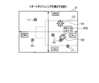
- FIG. 9 is a diagram showing an example of a clinical angle setting screen presented to the user during the clinical angle setting process.
- FIG. 10 is a block diagram showing a cooperative relationship among the system control unit 23, the display unit 27, the operation unit 21, and the drive unit 32.
- the image storage unit 22 associates the posture information (hereinafter referred to as imaging posture information) of the support device 10 when X-ray image data is actually acquired by X-ray imaging in association with the X-ray image data. store.
- the image storage unit 22 stores each of the plurality of X-ray images in association with imaging posture information of the support device 10 at the time of imaging the X-ray image.
- the display unit 27 displays a mark (hereinafter, referred to as an imaging posture mark) 105 corresponding to each imaging posture information on the clinical angle map.
- the image storage unit 22 stores posture information (hereinafter referred to as scheduled imaging posture information) of the posture of the support 10 scheduled for X-ray imaging (hereinafter referred to as scheduled imaging posture).
- the image storage unit 22 stores scheduled shooting posture information corresponding to at least one shooting scheduled posture.
- the display unit 27 displays at least one mark (hereinafter, referred to as a scheduled imaging posture mark) 107 corresponding to at least one scheduled imaging posture on the clinical angle map.
- the system control unit 23 performs shooting corresponding to the designated planned shooting posture mark 107.
- the drive unit 32 is controlled to place the support device 10 in the planned posture.
- FIG. 11 is a diagram illustrating a display example of auxiliary information displayed together with the target posture mark 103. That is, when the imaging posture mark 105 is designated by the user via the operation unit 21, the system control unit 23 reads out X-ray image data associated with the designated imaging posture mark 105. The display unit 27 displays the X-ray image data as the auxiliary information 103h together with the angle information.
- the shooting posture mark 105 may be specified by, for example, directly specifying the shooting posture mark 105 via the operation unit 21 or by superimposing the target posture mark 103 on the shooting posture mark 105. Accordingly, auxiliary information for setting the target posture can be presented to the user, so that the placement to the target posture can be performed more easily and appropriately.
- the user can recognize at a glance the posture in which the image collection is actually performed. Therefore, it is possible to prevent the user from forgetting to perform X-ray imaging in the posture intended for imaging. Particularly effective in routine inspections.
- the display unit 27 presents a large number of X-ray images obtained by X-ray imaging to the user in association with posture information of the supporter 10 at the time of X-ray imaging. Therefore, the X-ray diagnostic apparatus can easily reproduce the posture of the support 10 for taking a desired X-ray image.
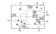
- FIGS. 12 and 13 are diagrams showing an example of a clinical angle setting screen presented to the user during the clinical angle setting process.
- the image storage unit 22 stores posture information (hereinafter referred to as registered posture information) of the posture of the support device 10 registered in advance (hereinafter referred to as registered posture information).
- the image storage unit 22 stores registered posture information corresponding to at least one registered posture.
- the display unit 27 displays at least one mark (hereinafter referred to as a registered posture mark) 111 corresponding to at least one registered posture on the clinical angle map.
- a desired registered posture mark 111 is designated by the user from the at least one registered posture mark 111 via the operation unit 21, the system control unit 23 supports the registered posture corresponding to the designated registered posture mark 111.
- the drive unit 32 is controlled to arrange the device 10.
- the display unit 27 may pop up the auxiliary information 103 h together with the target posture mark 103.
- the display unit 27 may display a mark (hereinafter referred to as a bed mark) 112 indicating the form of the bed 11 (more specifically, a couch) on the clinical angle map. .
- a bed mark indicating the form of the bed 11 (more specifically, a couch) on the clinical angle map.
- the display unit 27 may display a clinical angle map for supporting the auto angle function and the sequence automatic reproduction function. That is, the image storage unit 23 stores registered posture information (hereinafter referred to as auto angle posture information) corresponding to a registered posture for auto angle (hereinafter referred to as auto angle posture). The display unit 27 displays a mark (hereinafter referred to as “auto-angle posture mark”) 113 corresponding to the auto-angle posture on the clinical angle map. In addition, the image storage unit 23 includes a display unit 27 that stores registered posture information (hereinafter, sequence automatic reproduction function posture information) corresponding to a registered posture for the sequence automatic reproduction function (hereinafter referred to as a sequence automatic reproduction function posture). Called).
- registered posture information hereinafter referred to as auto angle posture information
- sequence automatic reproduction function posture information corresponding to a registered posture for the sequence automatic reproduction function
- sequence automatic reproduction function posture marks marks corresponding to a plurality of sequence automatic reproduction function postures (hereinafter referred to as sequence automatic reproduction function posture marks) 115 on the clinical angle map.
- sequence automatic reproduction function posture marks the display unit 27 may display the executed number of the total number of postures for the sequence automatic reproduction function on the clinical angle map.
- the display unit 27 may add a standard order of arrangement to the sequence automatic reproduction function posture to each of the plurality of sequence automatic reproduction function posture marks. As a result, the user can clearly grasp the arrangement order of each sequence automatic reproduction function posture.
- the system control unit 23 when the posture mark for automatic sequence reproduction function is specified by the user via the operation unit 21, the system control unit 23 performs the shooting program based on the shooting schedule information corresponding to the specified mark. And set target posture information related to auto-positioning. Further, according to the present example, in the routine inspection or the like, it is possible to prevent forgetting to take a picture in the planned shooting posture. As described above, according to the third embodiment, the auto angle function and the sequence automatic reproduction function can be used more effectively.
- the display unit 27 may further display such that the posture in which the support device 10 cannot be placed is clearly indicated on the clinical angle map.
- the same effects as those of the X-ray diagnostic apparatus according to the first embodiment can be obtained, and the clinical angle setting process can be further facilitated.
- the display unit 27 displays a clinical angle map in order to intuitively grasp the posture of the support device 10.
- the display target is not limited to the clinical angle map as long as the posture of the support device 10 can be intuitively grasped.
- the display unit 27 according to the fourth embodiment displays a schematic image that visually represents the posture of the supporter 10.
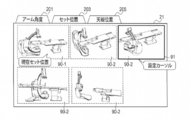
- FIG. 14 is a diagram showing an example of a set position setting screen presented to the user during the set position setting process.
- the display unit 27 according to the fourth embodiment displays a plurality of schematic images 90.
- the schematic image 90 is divided into a schematic image 90-1 representing the posture that the support device 10 takes at the present time and a schematic image 90-2 representing a predetermined posture set in advance.
- the image storage unit 23 stores posture information corresponding to the schematic image in association with each of the plurality of schematic images 90-2.
- the user designates a desired schematic image 90-2 from a plurality of schematic images 90-2 via the operation unit 21.
- the user designates the desired schematic image 90-2 by superimposing the setting cursor 91 on the desired schematic image 90-2 via the operation unit 21.
- the system control unit 23 controls the drive unit 32 to place the support device 10 in a posture corresponding to the designated schematic image 90-2.
- a tab 201 shown in FIG. 14 is a tab for switching to an operation screen for setting the posture of the C arm
- a tab 203 is a tab for switching to an operation screen for setting a “set position”
- a tab 205 is a bed.
- 11 is a tab for switching to an operation screen for setting the top plate position.
- a schematic image showing the posture of the support device 10 corresponding to each tab is displayed in the window.
- the display unit 27 does not necessarily have to display tabs. That is, all types of schematic images may be displayed in a single window.
- the X-ray diagnostic apparatus includes the X-ray tube 14-1, the X-ray detector 15, the support device 10, the image storage unit 23, and the display unit 27.
- the X-ray tube 14-1 generates X-rays.
- the X-ray detector 15 detects X-rays generated by the X-ray tube 14-1.
- the support device 10 supports the X-ray tube 14-1 and the X-ray detector 15 so as to be rotatable about a plurality of movable shafts.
- the image storage unit 23 stores angle information (attitude information) expressed by rotation angles around a plurality of movable axes regarding at least one preset attitude of the support device 10.
- the display unit 27 displays at least one first angle mark corresponding to at least one posture on a clinical angle map that is expressed by a coordinate system based on the plurality of movable axes that define the posture of the supporter 10.
- SYMBOLS 1 ... X-ray diagnostic apparatus, 10 ... Support device, 11 ... Bed, 14 ... X-ray irradiation part, 14-1 ... X-ray tube, 14-2 ... X-ray diaphragm, 15 ... X-ray detector, 18 ... Image Data generation unit, 18-1 ... arithmetic circuit, 18-2 ... storage circuit, 21 ... operation unit, 22 ... image storage unit, 23 ... system control unit, 27 ... display unit, 27-1 ... display image data generation circuit, 27-2 ... Monitor, 30 ... X-ray controller, 31 ... High voltage supply device, 31-1 ... High voltage generator, 31-2 ... High voltage controller, 32 ... Driver
Abstract
支持器の位置決めを直感的な操作で実行すること。 X線管14-1は、X線を発生する。X線検出器15は、X線管14-1により発生されたX線を検出する。支持器10は、X線管14-1とX線検出器15とを複数の可動軸に関して回動自在に支持する。画像保管部23は、支持器10についての予め設定された少なくとも1つの姿勢に関する、複数の可動軸回りの回転角度により表現される角度情報(姿勢情報)を記憶する。表示部27は、少なくとも1つの姿勢に対応する少なくとも1つの第1の角度マークを、支持器10の姿勢を規定する当該複数の可動軸に基づく座標系で表現する臨床角マップに表示する。
Description
実施形態は、X線診断装置に関する。
X線診断装置では、観察方向を変更する為に、例えばCアーム等の支持器を移動させる操作を行わなければならないことがある。この操作は、操作部を利用してユーザによる手入力等によって行われる。
このような観察位置の変更に係る操作・作業を容易にする為に、種々の技術が提案されている。例えば、特許文献1には、最適な観察方向(すなわち、撮影方向)を再現するために、X線画像診断装置の撮影部を構成するX線管及びX線検出器の被検体に対する位置決めを容易にする為の技術が開示されている。以下、この技術をオートポジショニングと呼ぶ。オートポジショニングは、支持器や寝台を所望の姿勢に配置する為の補助的な機能である。
また、特許文献2は、ルーチン検査等の、観察方向が予め決まっている検査を行う場合に、当該検査のシーケンスを予め登録しておくことで、実際の検査時の撮影プログラムの切り替えやオートポジショニングをシーケンス順に自動で再現する機能を開示している。この機能をシーケンス自動再現機能と呼ぶことにする。
特許文献3は、オートポジショニングで撮影角度を再現する際に、オートポジショニング機能で記憶された撮影角度の一覧をモニタに表示させる技術を開示している。
ところで、上述のオートポジショニングは、ユーザによるポジショニング番号の入力操作や多数の角度候補からの選択操作を必要とする。ポジショニング番号は、各登録位置に紐付けられた番号である。このポジショニング番号がユーザにより入力されることにより、支持器や寝台が所望の位置に位置決めされる(すなわち、所望の位置を再現する)。
ユーザは、再現したい支持器や寝台の姿勢(角度)については明確に認識しているが、当該姿勢に紐付けられたポジショニング番号を覚えているとは限らない。
このため、ユーザは、ポジショニング番号の選択時にモニタに表示される目標姿勢を逐一確認する必要がある。この確認作業は、ユーザにとって面倒である。従って、支持器を簡便に所望の姿勢に位置決めする為の技術が望まれている。
実施形態の目的は、支持器の位置決めを直感的な操作で実行可能なX線診断装置を提供することにある。
本実施形態に係るX線診断装置は、X線を発生するX線管と、前記X線管により発生されたX線を検出するX線検出器と、前記X線管と前記X線検出器とを複数の可動軸に関して回動自在に支持する支持部と、前記支持部についての予め設定された少なくとも1つの姿勢に関する、前記複数の可動軸回りの回転角度により表現される角度情報を記憶する記憶部と、前記少なくとも1つの姿勢に対応する少なくとも1つの第1の角度マークを、前記支持部の姿勢を規定する前記複数の可動軸に基づく座標系で表現する臨床角マップに表示する表示部と、を具備する。
支持器の位置決めを直感的な操作で実行することが可能となる。
以下、本実施形態に係るX線診断装置について説明する。
[第1実施形態]
図1は、第1実施形態に係るX線診断装置の一構成例を示すブロック図である。図1に示すように、第1実施形態に係るX線診断装置1は、支持器10、寝台11、X線照射部14、X線検出器15、画像データ生成部18、操作部21、画像保管部22、システム制御部23、表示部27、X線制御部30、高電圧供給装置31、及び駆動部32を備える。
図1は、第1実施形態に係るX線診断装置の一構成例を示すブロック図である。図1に示すように、第1実施形態に係るX線診断装置1は、支持器10、寝台11、X線照射部14、X線検出器15、画像データ生成部18、操作部21、画像保管部22、システム制御部23、表示部27、X線制御部30、高電圧供給装置31、及び駆動部32を備える。
支持器10は、X線照射部14とX線検出器15とを複数の可動軸に関して回動自在に支持する機構である。具体的には、支持器10は、Cアーム10-1と基台10-2とを有する。Cアーム10-1は、回転軸回りに回転可能にX線照射部14とX線検出器15とを支持する。基台10-2は、Cアーム10-1を回動軸に関して回動可能に支持している。回転軸と回動軸との交点はアイソセンタと呼ばれている。可動軸は回転軸と回動軸とを概念的に包含する軸であるとする。寝台11は、垂直方向及び水平方向に支持される。寝台11には被検体Pが載置される。
X線照射部14は、X線管14-1とX線絞り器14-2とを有する。X線管14-1は、高電圧発生器31-1に接続される。X線管14-1は、高電圧発生器31-1からのフィラメント電流の供給と高電圧の印加とを受けてX線を発生する。X線絞り器14-2は、X線管14-1に取り付けられる。X線絞り器14-2は、被検体Pへ照射されるX線の照射野を限定する。
X線検出器15は、X線管14-1により発生され被検体Pを透過したX線を検出する。
図2を参照しながら、支持器10に係る座標系(ガントリ座標系)について説明する。図2は、支持器10の駆動に係る座標系の一例を示す図である。図2に示すように、寝台11の長軸に平行する軸をz軸とし、寝台11の短軸に平行する軸をx軸とし、寝台11の上面に直交する軸をy軸とする。x軸、y軸、及びz軸は直交座標系を構成する。
X線管14-1の焦点とX線検出器15の検出面中心を結ぶ軸を撮影中心軸と呼ぶことにする。撮影中心軸のx軸に対する傾きは回転角度φに規定され、z軸に対する傾きは回転角度θに規定される。撮影中心軸がy軸に平行する場合、回転角度が基準角度、例えば、回転角度φ及び回転角度θが0度に規定される。基準角度を基準として、撮影中心軸の+x軸方向への傾き方向はLAO(Left Anterior Oblique View:第2斜位)に規定され、-x軸方向への傾きはRAO(Right Anterior Oblique View:第1斜位)方向に規定される。また、基準角度を基準として、撮影中心軸の-z軸方向への傾き方向はCRA(Cranial view:尾頭方向)に規定され、+z軸方向への傾き方向はCAU(Caudal view:頭尾方向)に規定される。
画像データ生成部18は、演算回路18-1と記憶回路18-2とを有する。演算回路18-1は、X線検出器15よりライン単位でデータを読み出し、読み出されたデータに基づいて透視画像データや撮影画像データ等の画像データを生成する。また、演算回路18-1は、生成した画像データに、システム制御部23から供給される撮影条件を関連づける。撮影条件としては、例えば、X線撮影時における支持器10の姿勢が挙げられる。支持器10の姿勢は、具体的には、上記のxyz座標系におけるCアーム10-1の配向を意味する。換言すれば、支持器10の姿勢は、寝台11に対するCアーム10-1の相対的な配向を意味する。記憶回路18-2は、演算回路18-1により生成された画像データを記憶する。
操作部21は、システム制御部23に接続され、X線診断装置1に対する各種操作の入力を受け付ける。例えば、操作部21は、タッチパネルやコントロールパネル、フットスイッチ、ジョイスティック等である。第1実施形態に係る操作部21としてはタッチパネルが挙げられる。すなわち、第1実施形態においては、タッチパネルを入力/出力装置として用いるとする。
画像保管部22は、X線画像データ等を記憶する記憶装置である。より詳細には、画像保管部22は、X線画像データに当該X線画像データのX線撮影時に支持器10がとる姿勢を示す情報を関連づけて記憶する。以下、姿勢を示す情報を姿勢情報と呼ぶことにする。姿勢情報は、具体的には、支持器10の回転角度に規定される。
システム制御部23は、X線診断装置1の各部を統括的に制御する。
表示部27は、種々の情報を表示する。具体的には、表示部27は、表示画像データ生成回路27-1とモニタ27-2とを有する。表示画像データ生成回路27-1は、X線検出器15によって生成された画像データを、モニタ27-2に表示される表示画像データに変換する。モニタ27-2は、表示画像データ生成回路27-1により生成された表示画像データを表示する。また、表示部27は、後述する臨床角マップを表示する。
X線制御部30は、システム制御部23による制御に従って高電圧供給装置31を制御する。
高電圧供給装置31は、高電圧発生器31-1と高電圧制御部31-2とを有する。高電圧発生器31-1は、高電圧制御部31-2による制御に従ってX線管14-1に高電圧を印加し、フィラメント電流を供給する。
駆動部32は、システム制御部23による制御に従って支持器10の回動、寝台11、及びX線絞り器14-2を個別に駆動する。
以下、図3乃至図5を参照して、第1実施形態に係るX線診断装置のシステム制御部23による臨床角設定処理について説明する。図3は、第1実施形態に係るX線診断装置による臨床角設定処理のフローチャートを示す図である。図4は、臨床角設定処理の際にユーザに呈示される臨床角設定画面の一例を示す図である。図5は、システム制御部23と表示部27・操作部21と駆動部32との相互の関わりを示すブロック図である。
まず、システム制御部23は、支持器10の現時点での姿勢を示す姿勢情報を、駆動部32から取得する(ステップS1)。以下、現在の支持器10の姿勢情報を現在姿勢情報と呼ぶことにする。具体的には、システム制御部23は、支持器10に設けられたロータリーエンコーダからの電気信号に基づいて、支持器10の現在姿勢情報(回転角度)を検出する。
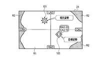
続いて、システム制御部23は、ステップS1で取得した現在姿勢情報を、操作部(タッチパネル)21に表示させる(ステップS2)。例えば、表示部27は、図4に示すように、現在姿勢情報に対応するマーク(以下、現在姿勢マークと呼ぶ)101を臨床角マップに表示する。臨床角マップは、支持器10の姿勢を規定する、支持器10が有する複数の可動軸に基づく座標系により規定されている。図4において臨床角マップは、縦軸が回転角度φに規定され、横軸が回転角度θに規定された直交座標系により規定されている。換言すれば、図4に示す臨床角マップは、縦軸がLAO及びRAOに規定され、横軸がCAU及びCRAに規定されている。表示部27は、現在姿勢マーク101に対応する回転角度に基づいて現在姿勢マーク101の臨床角マップにおける座標を特定し、特定された座標に現在姿勢マーク101を表示する。ユーザは、臨床角を示す直交座標系の座標平面上に表示された現在姿勢マーク101を目視することで、支持器10の現在の臨床角を定量的且つ感覚的に認識することができる。すなわち、操作部21は、支持器10の姿勢情報をグラフィカルに表示する表示部として機能する。より詳細には、支持器10の可動軸回りの回転角度をパラメータとする直交座標系の座標平面上で、現在姿勢情報を表示する表示部として機能する。
ここで、システム制御部23は、予め設定された支持器10の目標姿勢を示す目標姿勢情報が指定されたか否かを判定する(ステップS3)。第1実施形態においてユーザは、操作部21を操作して、目標姿勢情報に対応するマーク103を、臨床角マップ上の所望位置に位置させることで目標姿勢を指定する。以下、目標姿勢情報に対応するマークを目標姿勢マークと呼ぶことにする。目標姿勢マーク103が臨床角マップの所望位置に配置することにより、支持器10の目標姿勢が指定される。図4に示すように、表示部27は、ユーザによる区別を容易にするため、現在姿勢マーク101と目標姿勢マーク103とを異なる態様で表示すると良い。例えば、表示部27は、現在姿勢マーク101と目標姿勢マーク103とを異なるマークで表示することができる。また、表示部27は、現在姿勢マーク101と目標姿勢マーク103とを異なる色、形状、及び模様で表示しても良い。
また、表示部27は、現在姿勢マーク101と目標姿勢マーク103との各々の近傍に、当該マークに関する回転角度の数値を表示しても良い。例えば、図4に示すように、目標姿勢マーク103の近傍に当該マーク103に関する回転角度(RAO:20、CAU:10)が表示される。
なお、ステップS3をNOに分岐する場合は当該ステップS3へ戻る。換言すれば、ステップS3は、支持器10の目標姿勢が指定されるまで待つステップである。
ステップS3において目標姿勢が指定されたと判定した場合(ステップS3:YES)、システム制御部23は、指定された目標姿勢が配置可能であるか否かを判定する(ステップS4)。より詳細には、システム制御部23は、支持器10が指定された目標姿勢に配置可能であるか否かを、支持器10の現在姿勢の回転角度と支持器10の可動範囲とに基づいて判定する。システム制御部23は、指定された目標姿勢の回転角度が支持器10の可動範囲内にある場合、指定された目標姿勢が配置可能であると判定し、指定された目標姿勢の回転角度が支持器10の可動範囲内に無い場合、指定された目標姿勢が配置不可能であると判定する。可動範囲は、支持器10の現在姿勢と寝台11の姿勢との相対的関係に応じて変化する。すなわち、支持器10が寝台11に機械的に干渉する角度範囲が配置不能であると判定され、支持器10が寝台11に機械的に干渉しない角度範囲は配置可能であると判定される。
ステップS4において支持器10を目標姿勢に配置不可能あると判定した場合(ステップS4:NO)、システム制御部23は、“入力された目標姿勢に配置不可能である旨”をユーザに通知する(ステップS7)。すなわち、システム制御部23は、配置不可能である旨をユーザに通知する報知部として機能する。
具体的には、システム制御部23は、ステップS7において、例えば、タッチパネルが設けられたモニタ27-2に、“支持器10を目標姿勢に配置不可能なものである旨”を表示する。なお、このような表示による通知の他に、システム制御部23は、音声等により、その旨を通知しても良い。ステップS7の処理を終えた後、システム制御部23は、ステップS3の処理へ移行する。
ステップS4において支持器10を目標姿勢に配置可能であると判定した場合(ステップS4:YES)、システム制御部23は、現在姿勢情報と目標姿勢情報とに基づいて、支持器10を現在姿勢から目標姿勢まで回動させるのに要する回動量を算出する(ステップS5)。例えば、回動量は、現在姿勢の回転角度と目標姿勢の回転角度との差分に規定される。
そして、システム制御部23は、駆動部32を制御して、支持器10を目標姿勢に配置する(ステップS6)。ステップS6の処理を終えた後、システム制御部23は、ステップS3の処理へ移行する。
なお、上記の説明においては、システム制御部23により支持器10を目標姿勢に配置可能か否かを判定するものとした。しかしながら、本実施形態はこれに限定されない。例えば、表示部27は、臨床角マップにおいて支持器10が可動可能な角度範囲又は可動不能な角度範囲を明示しても良い。図6は、臨床角マップの他の表示例を示す図である。図6に示すように、臨床角マップは、可動可能範囲R1と可動不能範囲R2とに区分される。可動可能範囲R1と可動不能範囲R2とは、上記の通り、システム制御部23により、支持器10の現在姿勢の回転角度と可動範囲とに基づいて推定される。すなわち、支持器10が寝台11に機械的に干渉する角度範囲が可動不能範囲R2であると推定され、支持器10が寝台11に機械的に干渉しない角度範囲が可動可能範囲R1であると推定される。可動可能範囲R1と可動不能範囲R2とが明示されることによりユーザは、支持器10を目標姿勢に配置可能か否かを視覚的で判断することができる。
以上説明したように、第1実施形態によれば、ユーザが支持器10や寝台11を、直感的な操作で容易に所望の姿勢に配置可能なX線診断装置を提供することができる。換言すれば、本実施形態に係るX線診断装置は、支持器10の所望の回転角度、すなわち、所望の姿勢を再現すること可能となる。
具体的には、第1実施形態に係るX線診断装置は次の効果を実現する。
図3及び図5を参照して説明したようにシステム制御部23と操作部21とが協働することで、ユーザは図4に示す臨床角設定画面上で直観的に臨床角設定処理を行うことができる。従って、ユーザは、所望の姿勢(角度)の再現に必要となるポジショニング番号の記憶や確認等が不要となり、煩雑な処理を省略することができる。
これにより、手技時間の短縮が実現し、円滑な手技が可能となり、被ばく低減につながる。また、再現したい姿勢のポジショニング番号をユーザが思い出せない場合であっても、第1実施形態に係るX線診断装置によれば、再現したい姿勢を容易に直接入力して再現させることができる。
[応用例]
図7及び図8は、表示部27により表示される、目標姿勢マーク103と共に表示する補助情報の一表示例を示す図である。
図7及び図8は、表示部27により表示される、目標姿勢マーク103と共に表示する補助情報の一表示例を示す図である。
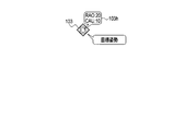
本応用例においてシステム制御部23は、ユーザが操作部21を介して臨床角マップに示された目標姿勢マーク103をクリックすると、当該目標姿勢マーク103に係る臨床角を定量的に示す補助情報(回転角度)103hを、図7に示すように表示させる。なお、表示部27は、補助情報103hとして、図8に示すように、当該目標姿勢マーク103に対応する姿勢をとる支持器10を模式的に表現する略図を表示しても良い。この略図103hは、操作部(タッチパネル)21を操作するユーザにより、当該目標姿勢マーク103に対応する姿勢を把握可能なように、操作部21側から見た支持器10を表現する略図であると良い。また、略図103hは、支持器10だけでなく、寝台11が描画されても良い。この場合、略図103は、支持器10と寝台との相対的な配置関係を模式的に表現することとなる。目標姿勢マークに関する目標姿勢情報と略図103とは画像保管部22により関連づけて記憶されている。表示部27は、ユーザにより目標姿勢マーク103が指定された場合、指定されたマーク103に関する目標姿勢情報に関連づけられた略図を画像保管部22から読み出し、読み出された略図を当該マーク103に近接して表示する。なお、図8に示すように、略図と回転角度とが並べて表示されても良い。
本応用例に係るX線診断装置は、目標姿勢を指定する際の補助的な情報をユーザに呈示することができる為、目標姿勢の指定作業をより容易且つ適切に行うことが可能となる。
[第2実施形態]
以下、第2実施形態に係るX線診断装置について説明する。説明の重複を避ける為に第1実施形態との相違点について説明する。従って、第1実施形態と共通する構成、作用、及び効果についての説明は適宜省略する。
以下、第2実施形態に係るX線診断装置について説明する。説明の重複を避ける為に第1実施形態との相違点について説明する。従って、第1実施形態と共通する構成、作用、及び効果についての説明は適宜省略する。
図9は、臨床角設定処理の際にユーザに呈示される臨床角設定画面の一例を示す図である。図10は、システム制御部23と表示部27・操作部21と駆動部32との協働関係を示すブロック図である。
上記の通り係る画像保管部22は、実際にX線撮影によってX線画像データを取得した時点における支持器10の姿勢情報(以下、撮影姿勢情報と呼ぶ)を、当該X線画像データに関連づけて保管する。画像保管部22は、複数のX線画像の各々に当該X線画像の撮影時点の支持器10の撮影姿勢情報を関連づけて記憶する。第2実施形態に係る表示部27は、図9に示すように、臨床角マップに各撮影姿勢情報に対応するマーク(以下、撮影姿勢マークと呼ぶ)105を表示する。
さらに、画像保管部22は、X線撮影予定の支持器10の姿勢(以下、撮影予定姿勢と呼ぶ)の姿勢情報(以下、撮影予定姿勢情報と呼ぶ)を記憶する。画像保管部22は、少なくとも1つの撮影予定姿勢に対応する撮影予定姿勢情報を記憶する。表示部27は、臨床角マップ上に少なくとも1つの撮影予定姿勢にそれぞれ対応する少なくとも1つのマーク(以下、撮影予定姿勢マークと呼ぶ)107を表示する。少なくとも1つの撮影予定姿勢マーク107の中からユーザにより操作部21を介して所望の撮影予定姿勢マーク107が指定された場合、システム制御部23は、指定された撮影予定姿勢マーク107に対応する撮影予定姿勢に支持器10を配置するために駆動部32を制御する。
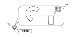
なお、上述した第1実施形態に係る応用例のように、目標姿勢マーク103と共に補助情報103hを表示させてもよい。図11は、目標姿勢マーク103と共に表示する補助情報の表示例を示す図である。すなわち、システム制御部23は、ユーザにより操作部21を介して撮影姿勢マーク105が指定された場合、指定された撮影姿勢マーク105に関連づけられたX線画像データを読み出す。表示部27は、当該X線画像データを角度情報と共に補助情報103hとして表示させる。撮影姿勢マーク105の指定は、例えば、操作部21を介して撮影姿勢マーク105が直接的に指定されても良いし、目標姿勢マーク103を撮影姿勢マーク105に重ねることにより指定されても良い。これにより、目標姿勢を設定する際の補助的な情報をユーザに呈示することが可能となる為、目標姿勢への配置をより容易且つより適切に行うことが可能となる。
以上説明したように、第2実施形態によれば、第1実施形態に係るX線診断装置と同様の効果を奏する上に、次の効果を奏するX線診断装置を提供することができる。
臨床角マップにおいて撮影姿勢マーク105が表示されることによりユーザは、画像収集を現実に実施した姿勢を一目瞭然で認識することができる。そのため、撮影予定の姿勢でのX線撮影の実行し忘れが防止される。特にルーチン検査等における効果が大きい。
また、表示部27は、X線撮影された多数のX線画像を、X線撮影時の支持器10の姿勢情報に対応付けてユーザに提示する。従ってX線診断装置は、所望のX線画像を撮影するための支持器10の姿勢を容易に再現することができる。
[第3実施形態]
以下、第3実施形態に係るX線診断装置について説明する。説明の重複を避ける為に第1実施形態との相違点について説明する。従って、第1実施形態と共通する構成、作用、及び効果についての説明は適宜省略する。
以下、第3実施形態に係るX線診断装置について説明する。説明の重複を避ける為に第1実施形態との相違点について説明する。従って、第1実施形態と共通する構成、作用、及び効果についての説明は適宜省略する。
図12及び図13は、臨床角設定処理の際にユーザに呈示される臨床角設定画面の一例を示す図である。
第3実施形態に係る画像保管部22は、予め登録された支持器10の姿勢(以下、登録姿勢と呼ぶ)の姿勢情報(以下、登録姿勢情報と呼ぶ)を記憶する。画像保管部22は、少なくとも1つの登録姿勢に対応する登録姿勢情報を記憶する。表示部27は、臨床角マップ上に少なくとも1つの登録姿勢にそれぞれ対応する少なくとも1つのマーク(以下、登録姿勢マークと呼ぶ)111を表示する。少なくとも1つの登録姿勢マーク111の中からユーザにより操作部21を介して所望の登録姿勢マーク111が指定された場合、システム制御部23は、指定された登録姿勢マーク111に対応する登録姿勢に支持器10を配置するために駆動部32を制御する。
図12に示すように、臨床角マップにおいて登録姿勢マーク111が表示されるため、ユーザこれを参照して目標姿勢マーク103を移動操作することで(登録姿勢マーク111上またはその近傍にドラッグ操作することで)、ユーザは支持器10を容易に所定の登録姿勢に配置することができる。なお、図12に示すように表示部27は、補助情報103hを、目標姿勢マーク103と共にポップアップ表示させてもよい。
なお、表示部27は、図12に示すように、臨床角マップに、寝台11(より詳細には、天板)の形態を示すマーク(以下、寝台マークと呼ぶ)112を表示しても良い。寝台マーク112が臨床角マップに表示されることによりユーザは、各マークが示す支持器10の姿勢と寝台11との相対的な位置をより明確に把握することが可能となる。
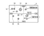
図13に示すように表示部27は、オートアングル機能及びシーケンス自動再現機能を支援するための臨床角マップを表示しても良い。すなわち、画像保管部23は、オートアングルのための登録姿勢(以下、オートアングル姿勢と呼ぶ)に対応する登録姿勢情報(以下、オートアングル用姿勢情報と呼ぶ)を記憶する。表示部27は、オートアングル姿勢に対応するマーク(以下、オートアングル用姿勢マークと呼ぶ)113を臨床角マップに表示する。また、画像保管部23は、表示部27は、シーケンス自動再現機能のための登録姿勢(以下、シーケンス自動再現機能用姿勢と呼ぶ)に対応する登録姿勢情報(以下、シーケンス自動再現機能用姿勢情報と呼ぶ)を記憶する。シーケンス自動再現機能においては、典型的には、一連の複数のシーケンス自動再現機能用姿勢が登録されている。表示部27は、複数のシーケンス自動再現機能用姿勢に対応するマーク(以下、シーケンス自動再現機能用姿勢マークと呼ぶ)115を臨床角マップに表示する。この際、表示部27は、複数のシーケンス自動再現機能用姿勢の全数のうちの実行済みの数を臨床角マップに表示すると良い。これによりユーザは、検査シーケンスの進捗状況を明確に把握することが可能となる。また、表示部27は、複数のシーケンス自動再現機能用姿勢マークの各々に当該シーケンス自動再現機能用姿勢への配置の標準的な順番を付すると良い。これによりユーザは、各シーケンス自動再現機能用姿勢への配置順序を明確に把握することが可能となる。
第3実施形態によれば、ユーザにより操作部21を介してシーケンス自動再現機能用姿勢マークが指定されると、システム制御部23は、指定されたマークに対応する撮影予定情報に基づいて撮影プログラムを切り替え、オートポジショニングに係る目標姿勢情報を設定する。また、本例によれば、ルーチン検査等において、撮影予定姿勢における撮影のし忘れが防止される。上述したように、第3実施形態によれば、オートアングル機能及びシーケンス自動再現機能を、より効果的に利用できるようになる。
なお表示部27は、支持器10が配置できない姿勢を臨床角マップ上で明示するような表示をさらに行っても良い。
かくして、第3実施形態によれば、第1実施形態に係るX線診断装置と同様の効果を奏する上に、臨床角設定処理のさらなる容易化がすることが可能となる。
[第4実施形態]
以下、本発明の第4実施形態に係るX線診断装置について説明する。説明の重複を避ける為に第1実施形態との相違点について説明する。従って、第1実施形態と共通する構成、作用、及び効果についての説明は適宜省略する。
以下、本発明の第4実施形態に係るX線診断装置について説明する。説明の重複を避ける為に第1実施形態との相違点について説明する。従って、第1実施形態と共通する構成、作用、及び効果についての説明は適宜省略する。
上記の実施形態において表示部27は、支持器10の姿勢を直感的に把握するために臨床角マップを表示した。しかしながら、支持器10の姿勢を直感的に把握することが可能であれば、表示対象は臨床角マップに限定されない。第4実施形態に係る表示部27は、支持器10の姿勢を視覚的に表現する模式画像を表示する。
図14は、セット位置設定処理の際にユーザに呈示されるセット位置設定画面の一例を示す図である。図14に示すように、第4実施形態に係る表示部27は、複数の模式画像90を表示する。模式画像90は、現時点において支持器10がとる姿勢を表現する模式画像90-1と予め設定された所定の姿勢を表現する模式画像90-2とに区分される。画像保管部23は、複数の模式画像90-2の各々に当該模式画像に対応する姿勢情報を関連づけて記憶している。ユーザは、操作部21を介して複数の模式画像90-2の中から所望の模式画像90-2を指定する。例えば、ユーザは、操作部21を介して設定カーソル91を所望の模式画像90-2に重ねることにより、所望の模式画像90-2を指定する。システム制御部23は、指定された模式画像90-2に対応する姿勢に支持器10を配置するために駆動部32を制御する。
なお、図14に示すタブ201はCアームの姿勢を設定する操作画面に切り替える為のタブであり、タブ203は“セット位置”を設定する操作画面に切り替える為のタブであり、タブ205は寝台11の天板位置を設定する操作画面に切り替える為のタブである。各タブに応じた支持器10の姿勢を示す模式画像がウィンドウに表示される。なお表示部27は、必ずしもタブを表示する必要はない。すなわち、単一のウィンドウに全ての種類の模式画像が表示されても良い。
上記の通り、本実施形態に係るX線診断装置は、X線管14-1、X線検出器15、支持器10、画像保管部23、及び表示部27を有している。X線管14-1は、X線を発生する。X線検出器15は、X線管14-1により発生されたX線を検出する。支持器10は、X線管14-1とX線検出器15とを複数の可動軸に関して回動自在に支持する。画像保管部23は、支持器10についての予め設定された少なくとも1つの姿勢に関する、複数の可動軸回りの回転角度により表現される角度情報(姿勢情報)を記憶する。表示部27は、少なくとも1つの姿勢に対応する少なくとも1つの第1の角度マークを、支持器10の姿勢を規定する当該複数の可動軸に基づく座標系で表現する臨床角マップに表示する。
上記の構成によりユーザは、配置すべき支持器10の姿勢を直感的に把握することができ、直感的な操作で支持器10の位置決め指示をすることができる
本発明のいくつかの実施形態を説明したが、これらの実施形態は、例として提示したものであり、発明の範囲を限定することは意図していない。これら新規な実施形態は、その他の様々な形態で実施されることが可能であり、発明の要旨を逸脱しない範囲で、種々の省略、置き換え、変更を行うことができる。これら実施形態やその変形は、発明の範囲や要旨に含まれるとともに、特許請求の範囲に記載された発明とその均等の範囲に含まれるものである。
本発明のいくつかの実施形態を説明したが、これらの実施形態は、例として提示したものであり、発明の範囲を限定することは意図していない。これら新規な実施形態は、その他の様々な形態で実施されることが可能であり、発明の要旨を逸脱しない範囲で、種々の省略、置き換え、変更を行うことができる。これら実施形態やその変形は、発明の範囲や要旨に含まれるとともに、特許請求の範囲に記載された発明とその均等の範囲に含まれるものである。
1…X線診断装置、10…支持器、11…寝台、14…X線照射部、14-1…X線管、14-2…X線絞り器、15…X線検出器、18…画像データ生成部、18-1…演算回路、18-2…記憶回路、21…操作部、22…画像保管部、23…システム制御部、27…表示部、27-1…表示画像データ生成回路、27-2…モニタ、30…X線制御部、31…高電圧供給装置、31-1…高電圧発生器、31-2…高電圧制御部、32…駆動部
Claims (12)
- X線を発生するX線管と、
前記X線管により発生されたX線を検出するX線検出器と、
前記X線管と前記X線検出器とを複数の可動軸に関して回動自在に支持する支持部と、
前記支持部についての予め設定された少なくとも1つの姿勢に関する、前記複数の可動軸回りの回転角度により表現される角度情報を記憶する記憶部と、
前記少なくとも1つの姿勢に対応する少なくとも1つの第1の角度マークを、前記支持部の姿勢を規定する前記複数の可動軸に基づく座標系で表現する臨床角マップに表示する表示部と、
を具備するX線診断装置。 - 前記支持部を駆動する駆動部と、
前記少なくとも1つの第1の角度マークのうちのユーザにより指定された角度マークに対応する姿勢に前記支持部を配置させるために前記駆動部を制御する制御部と、
をさらに備える請求項1記載のX線診断装置。 - 判定部と報知部とをさらに備え、
前記判定部は、前記支持部が前記指定された角度マークに対応する姿勢に配置可能であるか否かを、前記支持部の現在の姿勢と可動範囲とに基づいて判定し、
前記報知部は、前記判定部により前記指定された角度マークに対応する姿勢に配置可能でないと判定された場合、その旨を報知し、
前記制御部は、前記判定部により前記指定された角度マークに対応する姿勢をとることが可能であると判定された場合、前記支持部を前記指定された角度マークに対応する姿勢をとるように前記駆動部を制御する、
請求項2に記載のX線診断装置。 - 前記支持部の現在の姿勢に関する第2の角度情報を検出する検出部をさらに備え、
前記表示部は、前記第2の角度情報に対応する第2の角度マークを、前記少なくとも1つの第1の角度マークとともに前記臨床角マップに表示する、
請求項1記載のX線診断装置。 - 前記表示部は、前記第1の角度マークと前記第2の角度マークとを異なる態様で表示する、請求項4記載のX線診断装置。
- 前記臨床角マップは、横軸がCRA/CAUに規定され、縦軸がLAO/RAOに規定された直交2次元座標である、請求項1記載のX線診断装置。
- 前記表示部は、前記少なくとも1つの第1の角度マークとともに、前記少なくとも1つの角度マークに対応する姿勢において過去に撮影されたX線画像を表示する、請求項1記載のX線診断装置。
- 前記表示部は、前記少なくとも1つの第1の角度マークの中からユーザにより任意の角度マークが指定された場合、前記任意の角度マークに対応する姿勢において過去に撮影されたX線画像を、前記指定された角度マークとともに表示する、請求項7記載のX線診断装置。
- 前記表示部は、前記少なくとも1つの第1の角度マークとともに、前記少なくとも1つの角度マークに対応する姿勢をとる前記支持部を表現する略図を表示する、請求項1記載のX線診断装置。
- 前記表示部は、前記少なくとも1つの第1の角度マークの中からユーザにより任意の角度マークが指定された場合、前記任意の角度マークに対応する姿勢をとる前記支持部を表現する略図を、前記指定された角度マークとともに表示する、請求項9記載のX線診断装置。
- 前記表示部は、前記臨床角マップにおいて前記支持部が可動不能又は可動可能な角度範囲を明示する、請求項1記載のX線診断装置。
- X線を発生するX線管と、
前記X線管により発生されたX線を検出するX線検出器と、
前記X線管と前記X線検出器とを複数の可動軸に関して回動自在に支持する支持部と、
前記支持部を駆動する駆動部と、
前記支持部についての予め設定された少なくとも1つの姿勢を視覚的に表現する少なくとも1つの模式画像を記憶する記憶部と、
前記少なくとも1つの模式画像を表示する表示部と、
前記少なくとも1つの模式画像のうちのユーザにより指定された模式画像に対応する姿勢に前記支持部を配置させるために前記駆動部を制御する制御部と、
を具備するX線診断装置。
Priority Applications (2)
| Application Number | Priority Date | Filing Date | Title |
|---|---|---|---|
| CN201480011643.4A CN105025791A (zh) | 2013-03-04 | 2014-02-28 | X射线诊断装置 |
| US14/843,014 US20150374325A1 (en) | 2013-03-04 | 2015-09-02 | X-ray diagnostic apparatus |
Applications Claiming Priority (2)
| Application Number | Priority Date | Filing Date | Title |
|---|---|---|---|
| JP2013041738A JP2014168571A (ja) | 2013-03-04 | 2013-03-04 | X線診断装置 |
| JP2013-041738 | 2013-03-04 |
Related Child Applications (1)
| Application Number | Title | Priority Date | Filing Date |
|---|---|---|---|
| US14/843,014 Continuation US20150374325A1 (en) | 2013-03-04 | 2015-09-02 | X-ray diagnostic apparatus |
Publications (1)
| Publication Number | Publication Date |
|---|---|
| WO2014136669A1 true WO2014136669A1 (ja) | 2014-09-12 |
Family
ID=51491188
Family Applications (1)
| Application Number | Title | Priority Date | Filing Date |
|---|---|---|---|
| PCT/JP2014/055050 WO2014136669A1 (ja) | 2013-03-04 | 2014-02-28 | X線診断装置 |
Country Status (4)
| Country | Link |
|---|---|
| US (1) | US20150374325A1 (ja) |
| JP (1) | JP2014168571A (ja) |
| CN (1) | CN105025791A (ja) |
| WO (1) | WO2014136669A1 (ja) |
Families Citing this family (1)
| Publication number | Priority date | Publication date | Assignee | Title |
|---|---|---|---|---|
| CN111317490A (zh) * | 2020-02-25 | 2020-06-23 | 京东方科技集团股份有限公司 | 一种远程操作控制系统及远程操作控制方法 |
Citations (13)
| Publication number | Priority date | Publication date | Assignee | Title |
|---|---|---|---|---|
| JPS5675175A (en) * | 1979-11-26 | 1981-06-22 | Tokyo Shibaura Electric Co | Xxray positioning device |
| JPH01185247A (ja) * | 1988-01-19 | 1989-07-24 | Toshiba Corp | X線撮影装置 |
| JPH01126210U (ja) * | 1988-02-19 | 1989-08-29 | ||
| JPH04158846A (ja) * | 1990-10-24 | 1992-06-01 | Hitachi Medical Corp | X線保持装置 |
| JPH08289885A (ja) * | 1995-04-24 | 1996-11-05 | Toshiba Corp | X線診断装置 |
| JPH10234719A (ja) * | 1997-02-28 | 1998-09-08 | Toshiba Iyou Syst Eng Kk | X線診断装置 |
| JPH11285492A (ja) * | 1998-04-03 | 1999-10-19 | Hitachi Medical Corp | X線透視撮影装置および方法 |
| JP2003126084A (ja) * | 2001-10-24 | 2003-05-07 | Shimadzu Corp | アーム搭載型x線撮影装置 |
| JP2003135439A (ja) * | 2001-10-30 | 2003-05-13 | Shimadzu Corp | アーム搭載型x線撮影装置 |
| DE10200534A1 (de) * | 2002-01-09 | 2003-07-24 | Siemens Ag | Verfahren zum kollisionsfreien Bewegen wenigstens zweier gegeneinander bewegbarer Gegenstände |
| JP2006149858A (ja) * | 2004-11-30 | 2006-06-15 | Hitachi Medical Corp | 医用x線透視撮影装置 |
| JP2010017391A (ja) * | 2008-07-11 | 2010-01-28 | Shimadzu Corp | 放射線撮影装置 |
| JP2013233413A (ja) * | 2012-04-09 | 2013-11-21 | Toshiba Corp | X線診断装置 |
Family Cites Families (7)
| Publication number | Priority date | Publication date | Assignee | Title |
|---|---|---|---|---|
| US5155757A (en) * | 1990-06-20 | 1992-10-13 | Kabushiki Kaisha Toshiba | X-ray diagnosing apparatus |
| JPH09117444A (ja) * | 1995-10-26 | 1997-05-06 | Shimadzu Corp | ディジタルx線撮影装置 |
| JP3518573B2 (ja) * | 1997-01-24 | 2004-04-12 | 株式会社島津製作所 | X線検査装置 |
| JP2002119502A (ja) * | 2000-10-17 | 2002-04-23 | Toshiba Corp | 医用装置 |
| JP2006519629A (ja) * | 2002-08-06 | 2006-08-31 | ステリオタクシス インコーポレイテツド | 仮想的装置のインタフェースを使用した医療装置の遠隔制御 |
| CN101594824B (zh) * | 2006-06-28 | 2012-01-11 | 皇家飞利浦电子股份有限公司 | 基于预确定的最优视图映射图对ra确定最优旋转轨迹 |
| JP5075426B2 (ja) * | 2007-02-21 | 2012-11-21 | 株式会社東芝 | X線撮影装置およびオートポジショニング方法 |
-
2013
- 2013-03-04 JP JP2013041738A patent/JP2014168571A/ja active Pending
-
2014
- 2014-02-28 WO PCT/JP2014/055050 patent/WO2014136669A1/ja active Application Filing
- 2014-02-28 CN CN201480011643.4A patent/CN105025791A/zh active Pending
-
2015
- 2015-09-02 US US14/843,014 patent/US20150374325A1/en not_active Abandoned
Patent Citations (13)
| Publication number | Priority date | Publication date | Assignee | Title |
|---|---|---|---|---|
| JPS5675175A (en) * | 1979-11-26 | 1981-06-22 | Tokyo Shibaura Electric Co | Xxray positioning device |
| JPH01185247A (ja) * | 1988-01-19 | 1989-07-24 | Toshiba Corp | X線撮影装置 |
| JPH01126210U (ja) * | 1988-02-19 | 1989-08-29 | ||
| JPH04158846A (ja) * | 1990-10-24 | 1992-06-01 | Hitachi Medical Corp | X線保持装置 |
| JPH08289885A (ja) * | 1995-04-24 | 1996-11-05 | Toshiba Corp | X線診断装置 |
| JPH10234719A (ja) * | 1997-02-28 | 1998-09-08 | Toshiba Iyou Syst Eng Kk | X線診断装置 |
| JPH11285492A (ja) * | 1998-04-03 | 1999-10-19 | Hitachi Medical Corp | X線透視撮影装置および方法 |
| JP2003126084A (ja) * | 2001-10-24 | 2003-05-07 | Shimadzu Corp | アーム搭載型x線撮影装置 |
| JP2003135439A (ja) * | 2001-10-30 | 2003-05-13 | Shimadzu Corp | アーム搭載型x線撮影装置 |
| DE10200534A1 (de) * | 2002-01-09 | 2003-07-24 | Siemens Ag | Verfahren zum kollisionsfreien Bewegen wenigstens zweier gegeneinander bewegbarer Gegenstände |
| JP2006149858A (ja) * | 2004-11-30 | 2006-06-15 | Hitachi Medical Corp | 医用x線透視撮影装置 |
| JP2010017391A (ja) * | 2008-07-11 | 2010-01-28 | Shimadzu Corp | 放射線撮影装置 |
| JP2013233413A (ja) * | 2012-04-09 | 2013-11-21 | Toshiba Corp | X線診断装置 |
Also Published As
| Publication number | Publication date |
|---|---|
| CN105025791A (zh) | 2015-11-04 |
| JP2014168571A (ja) | 2014-09-18 |
| US20150374325A1 (en) | 2015-12-31 |
Similar Documents
| Publication | Publication Date | Title |
|---|---|---|
| JP4703119B2 (ja) | X線診断装置 | |
| US8781068B2 (en) | X-ray image diagnosing apparatus | |
| JP4375555B2 (ja) | X線ct装置 | |
| CN103327897B (zh) | 移动型x射线装置 | |
| JP5442381B2 (ja) | 医用画像撮影システム | |
| JP2014121364A (ja) | 放射線断層撮影装置およびプログラム | |
| JP6400307B2 (ja) | X線画像診断装置 | |
| JP2017080042A (ja) | X線画像診断装置 | |
| JP5881290B2 (ja) | X線撮影システム | |
| WO2015030091A1 (ja) | X線撮影装置およびx線透視画像表示方法 | |
| WO2013187174A1 (ja) | X線診断装置 | |
| WO2014136669A1 (ja) | X線診断装置 | |
| JP5553965B2 (ja) | 放射線画像撮影システム | |
| JP2009219552A (ja) | X線診断装置 | |
| JP2014161392A (ja) | 撮影、計測または治療を行う装置およびプログラム | |
| US20150374326A1 (en) | X-ray diagnostic apparatus | |
| JP2006122448A (ja) | X線映像装置 | |
| JP6083240B2 (ja) | 移動型x線撮影装置 | |
| JP2019118462A (ja) | 放射線画像表示装置および画像表示方法 | |
| JP2009291531A (ja) | X線診断装置 | |
| JP4016636B2 (ja) | アーム搭載型x線撮影装置 | |
| JP4534459B2 (ja) | 外科用x線装置 | |
| WO2024042823A1 (ja) | X線撮影装置 | |
| JP6367420B2 (ja) | X線診断装置 | |
| JP2008148982A (ja) | X線画像診断装置 |
Legal Events
| Date | Code | Title | Description |
|---|---|---|---|
| WWE | Wipo information: entry into national phase |
Ref document number: 201480011643.4 Country of ref document: CN |
|
| 121 | Ep: the epo has been informed by wipo that ep was designated in this application |
Ref document number: 14760902 Country of ref document: EP Kind code of ref document: A1 |
|
| NENP | Non-entry into the national phase |
Ref country code: DE |
|
| 122 | Ep: pct application non-entry in european phase |
Ref document number: 14760902 Country of ref document: EP Kind code of ref document: A1 |