WO2014136486A1 - Lentille zoom et dispositif d'imagerie équipé de celle-ci - Google Patents
Lentille zoom et dispositif d'imagerie équipé de celle-ci Download PDFInfo
- Publication number
- WO2014136486A1 WO2014136486A1 PCT/JP2014/051305 JP2014051305W WO2014136486A1 WO 2014136486 A1 WO2014136486 A1 WO 2014136486A1 JP 2014051305 W JP2014051305 W JP 2014051305W WO 2014136486 A1 WO2014136486 A1 WO 2014136486A1
- Authority
- WO
- WIPO (PCT)
- Prior art keywords
- recording
- layer
- interface
- optical information
- recording layer
- Prior art date
Links
Images


Classifications
-
- G—PHYSICS
- G11—INFORMATION STORAGE
- G11B—INFORMATION STORAGE BASED ON RELATIVE MOVEMENT BETWEEN RECORD CARRIER AND TRANSDUCER
- G11B7/00—Recording or reproducing by optical means, e.g. recording using a thermal beam of optical radiation by modifying optical properties or the physical structure, reproducing using an optical beam at lower power by sensing optical properties; Record carriers therefor
- G11B7/24—Record carriers characterised by shape, structure or physical properties, or by the selection of the material
- G11B7/241—Record carriers characterised by shape, structure or physical properties, or by the selection of the material characterised by the selection of the material
- G11B7/242—Record carriers characterised by shape, structure or physical properties, or by the selection of the material characterised by the selection of the material of recording layers
- G11B7/244—Record carriers characterised by shape, structure or physical properties, or by the selection of the material characterised by the selection of the material of recording layers comprising organic materials only
- G11B7/246—Record carriers characterised by shape, structure or physical properties, or by the selection of the material characterised by the selection of the material of recording layers comprising organic materials only containing dyes
-
- C—CHEMISTRY; METALLURGY
- C08—ORGANIC MACROMOLECULAR COMPOUNDS; THEIR PREPARATION OR CHEMICAL WORKING-UP; COMPOSITIONS BASED THEREON
- C08F—MACROMOLECULAR COMPOUNDS OBTAINED BY REACTIONS ONLY INVOLVING CARBON-TO-CARBON UNSATURATED BONDS
- C08F226/00—Copolymers of compounds having one or more unsaturated aliphatic radicals, each having only one carbon-to-carbon double bond, and at least one being terminated by a single or double bond to nitrogen or by a heterocyclic ring containing nitrogen
- C08F226/06—Copolymers of compounds having one or more unsaturated aliphatic radicals, each having only one carbon-to-carbon double bond, and at least one being terminated by a single or double bond to nitrogen or by a heterocyclic ring containing nitrogen by a heterocyclic ring containing nitrogen
-
- C—CHEMISTRY; METALLURGY
- C09—DYES; PAINTS; POLISHES; NATURAL RESINS; ADHESIVES; COMPOSITIONS NOT OTHERWISE PROVIDED FOR; APPLICATIONS OF MATERIALS NOT OTHERWISE PROVIDED FOR
- C09D—COATING COMPOSITIONS, e.g. PAINTS, VARNISHES OR LACQUERS; FILLING PASTES; CHEMICAL PAINT OR INK REMOVERS; INKS; CORRECTING FLUIDS; WOODSTAINS; PASTES OR SOLIDS FOR COLOURING OR PRINTING; USE OF MATERIALS THEREFOR
- C09D4/00—Coating compositions, e.g. paints, varnishes or lacquers, based on organic non-macromolecular compounds having at least one polymerisable carbon-to-carbon unsaturated bond ; Coating compositions, based on monomers of macromolecular compounds of groups C09D183/00 - C09D183/16
-
- G—PHYSICS
- G11—INFORMATION STORAGE
- G11B—INFORMATION STORAGE BASED ON RELATIVE MOVEMENT BETWEEN RECORD CARRIER AND TRANSDUCER
- G11B7/00—Recording or reproducing by optical means, e.g. recording using a thermal beam of optical radiation by modifying optical properties or the physical structure, reproducing using an optical beam at lower power by sensing optical properties; Record carriers therefor
- G11B7/24—Record carriers characterised by shape, structure or physical properties, or by the selection of the material
- G11B7/2403—Layers; Shape, structure or physical properties thereof
- G11B7/24035—Recording layers
- G11B7/24038—Multiple laminated recording layers
-
- G—PHYSICS
- G11—INFORMATION STORAGE
- G11B—INFORMATION STORAGE BASED ON RELATIVE MOVEMENT BETWEEN RECORD CARRIER AND TRANSDUCER
- G11B7/00—Recording or reproducing by optical means, e.g. recording using a thermal beam of optical radiation by modifying optical properties or the physical structure, reproducing using an optical beam at lower power by sensing optical properties; Record carriers therefor
- G11B7/24—Record carriers characterised by shape, structure or physical properties, or by the selection of the material
- G11B7/241—Record carriers characterised by shape, structure or physical properties, or by the selection of the material characterised by the selection of the material
- G11B7/242—Record carriers characterised by shape, structure or physical properties, or by the selection of the material characterised by the selection of the material of recording layers
- G11B7/244—Record carriers characterised by shape, structure or physical properties, or by the selection of the material characterised by the selection of the material of recording layers comprising organic materials only
- G11B7/245—Record carriers characterised by shape, structure or physical properties, or by the selection of the material characterised by the selection of the material of recording layers comprising organic materials only containing a polymeric component
-
- C—CHEMISTRY; METALLURGY
- C08—ORGANIC MACROMOLECULAR COMPOUNDS; THEIR PREPARATION OR CHEMICAL WORKING-UP; COMPOSITIONS BASED THEREON
- C08F—MACROMOLECULAR COMPOUNDS OBTAINED BY REACTIONS ONLY INVOLVING CARBON-TO-CARBON UNSATURATED BONDS
- C08F220/00—Copolymers of compounds having one or more unsaturated aliphatic radicals, each having only one carbon-to-carbon double bond, and only one being terminated by only one carboxyl radical or a salt, anhydride ester, amide, imide or nitrile thereof
- C08F220/02—Monocarboxylic acids having less than ten carbon atoms; Derivatives thereof
- C08F220/10—Esters
- C08F220/12—Esters of monohydric alcohols or phenols
- C08F220/16—Esters of monohydric alcohols or phenols of phenols or of alcohols containing two or more carbon atoms
- C08F220/18—Esters of monohydric alcohols or phenols of phenols or of alcohols containing two or more carbon atoms with acrylic or methacrylic acids
- C08F220/1807—C7-(meth)acrylate, e.g. heptyl (meth)acrylate or benzyl (meth)acrylate
-
- G—PHYSICS
- G11—INFORMATION STORAGE
- G11B—INFORMATION STORAGE BASED ON RELATIVE MOVEMENT BETWEEN RECORD CARRIER AND TRANSDUCER
- G11B7/00—Recording or reproducing by optical means, e.g. recording using a thermal beam of optical radiation by modifying optical properties or the physical structure, reproducing using an optical beam at lower power by sensing optical properties; Record carriers therefor
- G11B7/24—Record carriers characterised by shape, structure or physical properties, or by the selection of the material
- G11B7/2403—Layers; Shape, structure or physical properties thereof
- G11B7/24047—Substrates
- G11B7/2405—Substrates being also used as track layers of pre-formatted layers
-
- G—PHYSICS
- G11—INFORMATION STORAGE
- G11B—INFORMATION STORAGE BASED ON RELATIVE MOVEMENT BETWEEN RECORD CARRIER AND TRANSDUCER
- G11B7/00—Recording or reproducing by optical means, e.g. recording using a thermal beam of optical radiation by modifying optical properties or the physical structure, reproducing using an optical beam at lower power by sensing optical properties; Record carriers therefor
- G11B7/24—Record carriers characterised by shape, structure or physical properties, or by the selection of the material
- G11B7/241—Record carriers characterised by shape, structure or physical properties, or by the selection of the material characterised by the selection of the material
- G11B7/252—Record carriers characterised by shape, structure or physical properties, or by the selection of the material characterised by the selection of the material of layers other than recording layers
- G11B7/256—Record carriers characterised by shape, structure or physical properties, or by the selection of the material characterised by the selection of the material of layers other than recording layers of layers improving adhesion between layers
Definitions
- the present invention relates to an optical information recording medium containing a polymer compound in a recording layer.
- an optical information recording medium having a recording layer and an intermediate layer for example, in Patent Documents 1 to 3, the recording layer has a polymer compound (polymer binder) and a dye dispersed in the polymer binder.
- Patent Document 1 describes that an optical information recording medium having a multi-layered recording layer preferably contains a multiphoton absorbing dye in order to minimize the influence on the adjacent recording layer during recording and reproduction. ing.
- JP 2012-89195 A Japanese Patent No. 2101521 Japanese Patent No. 2771231
- the dye dispersed in the polymer binder in the recording layer may diffuse into an adjacent layer, for example, an intermediate layer over time.
- the dye diffuses into the intermediate layer for example, light is less likely to be reflected at the interface between the recording layer and the intermediate layer, which may reduce information recording and reading performance. Therefore, the optical information recording medium in which the dye is dispersed in the recording layer may cause a problem in long-term stability such as storage stability.
- the recording layer contains a multiphoton absorbing dye
- an ultrashort pulse laser with a high peak power is required to record information.
- the optical recording apparatus becomes expensive. Therefore, an optical information recording medium having a low peak power and capable of recording information even with a semiconductor laser or the like used for conventional optical recording is desired.
- the sensitivity of the recording material is as high as possible.
- an object of the present invention is to provide an optical information recording medium which is excellent in long-term stability and can be recorded by a laser having a small peak power.
- the present invention is an optical information recording medium having one or more recording layers, and the recording layer includes a recording material in which a one-photon absorbing dye is bonded to a polymer compound.
- the coupling strength ⁇ 2 between the polymer compound and the one-photon absorption dye is higher than that in the state where the one-photon absorption dye is dispersed in the polymer compound.
- the recording material includes the polymer compound to which the dye is bonded, the dye can be prevented from diffusing into an adjacent layer, for example, the intermediate layer. Long-term stability can be improved. Further, since the dye is a one-photon absorption dye, information can be recorded by a laser having a small peak power. Furthermore, since the recording material has a higher coupling strength between the polymer compound and the one-photon absorption dye than in the state where the one-photon absorption dye is dispersed in the polymer compound, the recording sensitivity is high. High and good.
- the number of atoms involved in the binding between the polymer compound and the one-photon absorption dye is less than 10.
- the recording sensitivity can be improved.
- an intermediate layer may be provided between the recording layers.
- the present invention can be applied to a multilayer optical information recording medium.
- the recording material of the present invention has good sensitivity even when a one-photon absorption dye is used, so that recording can be performed even when the absorption rate of the recording layer is low (that is, even when the transmittance is high). Therefore, many recording layers can be provided and the capacity can be increased.
- the recording layer forms a first interface and a second interface with the intermediate layer sandwiching the recording layer, and the one-photon absorbing dye absorbs the recording light and generates heat. It is possible to adopt a configuration in which information is recorded by deforming and forming a convex shape toward the intermediate layer at least one of the first interface and the second interface.
- the recording layer can have a thickness of 50 nm or more.
- a convex shape is easily formed by setting the thickness of the recording layer to 50 nm or more.
- the intermediate layer forming the interface where the convex shape is formed is softer than the recording layer. This is because the intermediate layer forming the interface on which the convex shape is formed is softer than the recording layer, so that the interface is easily deformed and information recording by the convex shape is facilitated.
- middle layer can be confirmed by pressing each material which comprises each other. That is, it can be confirmed that when the materials are pressed against each other, it is softer to be largely recessed.
- the glass transition temperature of the intermediate layer forming the interface where the convex shape is formed can be lower than the glass transition temperature of the recording layer. Also in this case, the intermediate layer forming the interface where the convex shape is formed is more easily deformed than the recording layer, and information recording by the convex shape is facilitated.
- the intermediate layer forming the interface where the convex shape is formed is, for example, an adhesive layer.
- a convex shape is formed only at one of the first interface and the second interface by irradiation of recording light, and the convex is formed at the other interface.
- the difference in refractive index between the recording layer and the intermediate layer that forms the interface where the convex shape is not formed is the difference in refractive index between the recording layer and the intermediate layer that forms the interface where the convex shape is not formed. It is desirable to be large.
- the interface on which the convex shape is formed is used for reading information, the difference in refractive index between the materials on both sides of the interface is large, so that the interface reflectance becomes relatively large and information can be read easily.
- the interface where the convex shape is not formed is not used for reading information, the light used for recording / reading (hereinafter referred to as recording / reading light) is transmitted by reducing the refractive index difference between the materials on both sides of the interface.
- the rate specifically, the combined transmittance of the first interface and the second interface can be increased.
- the recording layer is multi-layered, light can reach a recording layer deep as viewed from the recording-reading light irradiation side, which is advantageous in increasing the recording capacity by multi-layering.
- the difference between the refractive index of the intermediate layer that forms the interface where the convex shape is not formed and the refractive index of the recording layer is preferably 0.05 or less.
- the reflectance of light at the interface is substantially zero, when the recording layer is formed in multiple layers, the light can reach the recording layer deep as viewed from the irradiation side of the recording / reading light. Therefore, it is advantageous to increase the recording capacity by multilayering.
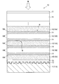
- an optical information recording medium 10 includes a substrate 11, a reflective layer 12, a spacer layer 13, a plurality of recording layers 14, and a plurality of intermediate layers 15 (adhesive layer 15A). And a recording layer support layer 15B), a cover layer 16, and a hard coat layer 17.
- the interface formed between the recording layer 14 and the pressure-sensitive adhesive layer 15A is referred to as a recording interface 18A as an example of the first interface, and between the recording layer 14 and the recording layer support layer 15B.
- the interface formed in this is called a non-recording interface 18B as an example of the second interface.
- the substrate 11 is a support for supporting the recording layer 14, the intermediate layer 15, and the like, and is made of, for example, a polycarbonate disk.
- the material of the substrate 11 is not particularly limited.
- the substrate 11 preferably has a thickness in the range of 0.02 mm to 2 mm.
- the substrate 11 of the present embodiment is provided with irregularities (servo signals) that serve as guides for performing tracking servo on the incident-side surface (the upper surface in the drawing) of the recording / reading light, and the guide layer 11A also serves as a guide layer 11A.
- the guide layer 11A may be a layer in which a servo signal is recorded by a change in refractive index or the like.
- the guide layer 11 ⁇ / b> A may be provided as a layer different from the substrate 11.
- the reflective layer 12 is a layer for reflecting servo light, and is made of an aluminum thin film or the like deposited on the uneven surface of the substrate 11 (guide layer 11A). By having such a reflective layer 12, the servo signal can be detected on the servo light incident side, so that the configuration of the reproducing apparatus can be simplified.
- the spacer layer 13 is a layer for adjusting the interval between the recording layer 14 and the guide layer 11A, and is made of a thermoplastic resin, a thermosetting resin, an ultraviolet curable resin, an adhesive, or the like.
- the spacer layer 13 preferably has a thickness in the range of 5 ⁇ m to 100 ⁇ m.
- the recording layer 14 is a layer made of a photosensitive material on which information is optically recorded.
- the recording layer 14 includes a high molecular compound to which a one-photon absorption dye that absorbs recording light is covalently bonded.
- the coupling strength ⁇ 2 between the polymer compound and the one-photon absorption dye is higher than that in the state where the one-photon absorption dye is dispersed in the polymer compound.
- the coupling strength here is a value that depends on the strength of the energy interaction between the dye and the polymer compound (polymer).
- the large coupling strength means that the amount of energy exchanged between the dye and the polymer. Means big.
- the coupling intensity can be obtained by measuring the echo peak shift, obtaining a correlation function of energy fluctuation from the echo peak shift, and numerically calculating the obtained correlation function.
- the echo peak shift measurement can use the three-pulse photon echo measurement in the following reference [1]. Further, numerical calculation here is performed in the same manner as the following references [2] to determine the coupling strength (coupling strength) ⁇ 2 as follows.
- M (T) a correlation function (M (T)) of energy fluctuation is experimentally obtained from the echo peak shift.
- M (T) uses the following function.
- A is a coefficient of each component
- ⁇ is an attenuation time constant
- a subscript represents each component.
- T is the population time
- ⁇ is the initial phase
- ⁇ is the vibration frequency, which are experimentally determined from the echo peak shift. From this correlation function, Ask for.
- ⁇ is an integral variable.
- (lambda) is rearrangement energy and becomes like following Formula.
- M (T) is expressed by the following equation using the spectral density (C ( ⁇ )).
- ⁇ 2 is the coupling strength and is given by the following equation.
- Coupling intensity, rearrangement energy, and spectral density are obtained by numerically calculating the absorption spectrum, emission spectrum, and echo signal according to the following equations and corresponding to the experimental data.
- the absorption and emission spectra are represented by formula (6) and formula (7), respectively.
- t is an integral variable.
- each variable t represents the order of three pulse irradiations.
- T 1 is the population decay time
- ⁇ is the coherent time
- T is the population time.
- ⁇ eg is the transition frequency between the electronic ground state and the excited state.
- E is the electric field of the laser pulse.
- R (t 1 , t 2 , t 3 ) in equation (9) is as follows and is related to equation (2).
- t 1 , t 2 , and t 3 are times when the pulsed light reaches the sample.
- the recording material “the coupling strength between the polymer compound and the one-photon absorption dye is increased” is that a certain polymer compound and one-photon absorption dye are specified, The coupling strength of the recording material in which the one-photon absorption dye is dispersed, and the coupling strength of the recording material bonded in a state where the polymer compound and the one-photon absorption dye are bonded are measured, and the latter coupling is measured.
- the number of atoms involved in the binding between the polymer compound and the one-photon absorption dye is less than 10.
- the number of atoms involved in the binding between the polymer compound and the one-photon absorption dye is the number of atoms that linearly bonds the polymer compound and the chromophore of the one-photon absorption dye.
- the number of atoms involved in the bond is 3 when the atoms A1 to A3 are counted.
- the one-photon absorption dye that absorbs recording light for example, a dye conventionally used as a heat mode type recording material can be used. Specifically, methine dyes (cyanine dyes, hemicyanine dyes, styryl dyes, oxonol dyes, merocyanine dyes, etc.), macrocyclic dyes (phthalocyanine dyes, naphthalocyanine dyes, porphyrin dyes, etc.), azo dyes (including azo metal chelate dyes) ), Arylidene dyes, complex dyes, coumarin dyes, azole derivatives, triazine derivatives, benzotriazole derivatives, benzophenone derivatives, phenoxazine derivatives, phenothiazine derivatives, 1-aminobutadiene derivatives, cinnamic acid derivatives, quinophthalone dyes, and the like can be used. .
- methine dyes cyanine dyes, hemicyan
- polymer compound that binds the one-photon absorption dye examples include polyvinyl acetate (PVAc), polymethyl methacrylate (PMMA), polyethyl methacrylate, polybutyl methacrylate, polybenzyl methacrylate, polyisobutyl methacrylate, and polycyclohexyl methacrylate.
- PC Polycarbonate
- PS polystyrene
- PVC polyvinyl chloride
- PVA polyvinyl alcohol
- vinyl polypivalate vinyl polypivalate
- polyethyl acrylate polybutyl acrylate
- polyacenaphthylene polyvinyl naphthalene
- polyvinyl Carbazole polymaleimide
- polyvinyl phthalimide polyindene
- cycloolefin polymer and the like can be used.
- the recording material has a coupling strength higher than that obtained by dispersing the one-photon absorbing dye in the polymer compound by combining the one-photon absorbing dye and the polymer compound in a certain state. It's getting bigger.
- a compound A having the following chemical structural formula can be used as the polymer compound to which the one-photon absorption dye.
- Compound A is obtained by covalently bonding a benzotriazole derivative as a one-photon absorption dye to polybenzyl methacrylate as a polymer compound.
- the recording layer 14 When the recording layer 14 is irradiated with recording light, the polymer compound is deformed by the heat generated by the one-photon absorbing dye absorbing the recording light, and the convexity toward the intermediate layer 15 (adhesive layer 15A) is formed on the recording interface 18A.
- This is a layer in which dot-shaped recording marks M (information) are recorded by forming the shape.
- the recording mark M has a convex shape in the center from the recording layer 14 toward the pressure-sensitive adhesive layer 15A, and a concave shape (before deformation) from the pressure-sensitive adhesive layer 15A toward the recording layer 14 around the convex shape. It may have a concave shape with respect to the recording interface 18A.
- the recording layer 14 is formed thicker than a conventional recording layer containing a polymer binder and a dye, and the thickness of one recording layer 14 is preferably 50 nm or more.
- the recording layer / intermediate layer interface (corresponding to the recording interface 18A and the non-recording interface 18B in this embodiment) is recorded as in the known recording technique by deformation of the recording layer.
- the layer is deformed into a concave shape with reference to the layer, but when the thickness is 50 nm or more, the center of the recorded portion is deformed to be convex.
- the upper limit of the thickness of the recording layer 14 is not particularly limited, but is desirably 5 ⁇ m or less in order to increase the number of recording layers 14 as much as possible. Furthermore, the thickness of the recording layer 14 is more preferably in the range of 100 nm to 3 ⁇ m, and particularly preferably in the range of 200 nm to 2 ⁇ m. In the present embodiment, the recording layer 14 has a thickness of 1 ⁇ m as an example.
- the recording layer 14 is provided with, for example, about 2 to 100 layers. In order to increase the storage capacity of the optical information recording medium 10, it is desirable that the number of the recording layers 14 be large, for example, 10 layers or more. Thereby, the capacity of the optical information recording medium 10 can be increased.
- the recording layer 14 is made of a material whose refractive index does not substantially change before and after recording that deforms the recording interface 18A.
- the recording layer 14 desirably has an absorptance (one-photon absorptance) with respect to recording light of 10% or less per layer. Further, in order to increase the number of recording layers 14, it is preferable that the absorption rate is as small as possible as long as recording is possible. Therefore, the absorption rate of the recording layer 14 is more preferably 8% or less, and 5% or less. More preferably, it is more preferably 3% or less.
- the recording layer 1 On condition that the intensity of the recording light reaching the innermost recording layer 14 is 50% or more of the intensity of the irradiated recording light, in order to realize the eight recording layers, the recording layer 1 This is because the absorptance per layer needs to be 8% or less, and in order to realize 20 recording layers, the absorptance per recording layer needs to be 3% or less.
- the absorptance is high, the number of layers is reduced, and the effect of increasing the recording capacity due to multilayering is reduced.
- a recording material having a high coupling strength between the polymer compound and the one-photon absorption dye is used as in the present invention, a relatively high recording sensitivity can be obtained even if the absorption rate is small. it can. Therefore, it is possible to increase the capacity by increasing the number of recording layers 14.
- the polymer compound contained in the recording layer 14 has a mass ratio of the one-photon absorbing dye of less than 50%, in other words, a mass ratio of the polymer compound of 50% or more (the polymer compound is the main component). Is desirable).
- a convex shape (record mark M) having a sufficient height (projection amount) can be formed with reference to the recording interface 18A before deformation.
- the convex shape is formed by thermal expansion of the polymer compound due to the absorption of the recording light, and then rapid cooling while maintaining the expanded shape by stopping the irradiation of the recording light. Therefore, the mass ratio of the one-photon absorption dye is 50%.
- the mass ratio of the polymer compound is less than 50%
- the material of the polymer compound thermally expanded due to the absorption of the recording light flows out to the periphery, so that the convex shape is hardly formed.
- the formation method of the recording layer 14 is not particularly limited, but the recording layer 14 can be formed by a spin coating method, a blade coating method, or the like using a solution in which a polymer compound to which a one-photon absorption dye is bonded is dissolved in a solvent.
- a solvent As the solvent at this time, dichloromethane, chloroform, methyl ethyl ketone (MEK), acetone, methyl isobutyl ketone (MIBK), toluene, hexane, propylene glycol monomethyl ether acetate (PGMEA), cyclohexanone, or the like can be used.
- the intermediate layer 15 is provided between the plurality of recording layers 14, in other words, adjacent to the upper and lower sides of each recording layer 14 in the drawing. More specifically, the intermediate layer 15 includes an adhesive layer 15A and a recording layer support layer 15B, and the adhesive layer 15A and the recording layer support layer 15B are alternately arranged between the plurality of recording layers 14. Yes. In other words, the single recording layer 14 is disposed so as to be sandwiched between the pressure-sensitive adhesive layer 15A and the recording layer support layer 15B. In this embodiment, the pressure-sensitive adhesive layer 15A is viewed from the substrate 11 side. The recording layer 14, the recording layer support layer 15B, and the recording layer 14 are repeatedly arranged in this order.
- the intermediate layer 15 is provided in order to provide a predetermined amount of space between the recording layers 14 so that interlayer crosstalk does not occur between the plurality of recording layers 14. For this reason, the intermediate layer 15 preferably has a thickness of 2 ⁇ m or more, and more preferably 5 ⁇ m or more. Further, the intermediate layer 15 is preferably thin as long as interlayer crosstalk does not occur. For example, the thickness is preferably 20 ⁇ m or less. In the present embodiment, the intermediate layer 15 (the pressure-sensitive adhesive layer 15A and the recording layer support layer 15B) has a thickness of 10 ⁇ m as an example.
- the pitch of the recording interface 18A is not a constant pitch of 10 ⁇ m, 12 ⁇ m, 10 ⁇ m, 12 ⁇ m,.
- the influence of the reproduction light, which is reflected light from the recording interface 18A being reproduced, and the reflected light of the readout light at the recording interface 18A adjacent to the recording interface 18A being reproduced, on the reproduction light is reduced. be able to.
- the intermediate layer 15 is made of a material that does not change due to laser irradiation during recording and reproduction.
- the intermediate layer 15 substantially reduces recording light, reading light, and reproducing light in order to minimize the loss of recording light, reading light, and reproducing light (light including a reproduction signal generated by irradiation of the reading light). It is desirable to use a material that does not absorb, in other words, a material that is transparent to recording light, reading light, and reproducing light.
- transparent here means that the absorptance is 1% or less.
- the pressure-sensitive adhesive layer 15 ⁇ / b> A has adhesiveness that allows attachment to other surfaces and is softer than the recording layer 14.
- the pressure-sensitive adhesive layer 15 ⁇ / b> A has a glass transition temperature lower than that of the recording layer 14.
- the pressure-sensitive adhesive layer 15A which is softer than the recording layer 14, is used as the intermediate layer 15 adjacent to one surface of the recording layer 14, so that when the recording layer 14 is heated by the recording light and expanded, The layer 15 is easily deformed, and the recording interface 18A can be easily deformed.
- the recording layer support layer 15B is formed of an ultraviolet curable resin or the like, and has the same hardness as the recording layer 14 or is harder than the recording layer 14.
- the recording layer support layer 15B has a glass transition temperature higher than the glass transition temperature of the recording layer.
- a convex shape is not formed at the non-recording interface 18B, which is the interface between the recording layer and the recording layer support layer 15B, and only the recording interface 18A, which is the interface between the recording layer 14 and the pressure-sensitive adhesive layer 15A. (Record mark M) is formed.
- the refractive index of the pressure-sensitive adhesive layer 15A and the refractive index of the recording layer support layer 15B are different from each other, and the refractive index of the recording layer support layer 15B and the refractive index of the recording layer 14 are substantially the same.
- the refractive index of the recording layer 14 and the refractive index of the recording layer support layer 15B are set such that the refractive index of the recording layer 14 is n1, and the refractive index of the recording layer support layer 15B is n3. ((N3 ⁇ n1) / (n3 + n1)) 2 ⁇ 0.0003 It is desirable that the reflectance at the non-recording interface 18B is equal to a certain level of 0.0003 or less.
- the refractive index of the recording layer 14 and the refractive index of the recording layer support layer 15B are preferably close to each other in order to eliminate reflection at the interface between the two layers (non-recording interface 18B).
- the difference in refractive index of 15B is preferably 0.05 or less, more preferably 0.03 or less, still more preferably 0.01 or less, and most preferably 0.
- n1 of the recording layer 14 is 1.565
- n3 of the recording layer support layer 15B is 1.564
- ((n3 ⁇ n1) / (n3 + n1)) 2 is almost zero. .
- the refractive index of the pressure-sensitive adhesive layer 15A and the refractive index of the recording layer 14 are different from each other, and it is preferable that the difference be appropriately provided.
- the difference in refractive index between the pressure-sensitive adhesive layer 15A and the recording layer 14 is preferably larger than the difference in refractive index between the recording layer support layer 15B and the recording layer 14, and is 0.11 or less. .
- the refractive index of the recording layer 14 and the refractive index of the pressure-sensitive adhesive layer 15A are expressed as follows: 0.0005 ⁇ ((n2 ⁇ n1) / (n2 + n1)) 2 ⁇ 0.04 It is desirable that the reflectance at the recording interface 18A be different to some extent between 0.0005 and 0.04.
- the reflectance is 0.0005 or more, the amount of reflected light at the recording interface 18A can be increased, and the S / N ratio can be increased during information reproduction. Further, since the reflectance is 0.04 or less, the amount of reflected light at the recording interface 18A is suppressed to an appropriate level, and the recording / reading light is not greatly attenuated during recording and reproduction, and the deep recording layer 14 Allows to reach. This makes it possible to increase the capacity by providing a large number of recording layers 14. As an example, if the refractive index n1 of the recording layer 14 is 1.565 and the refractive index n2 of the pressure-sensitive adhesive layer 15A is 1.477, ((n2 ⁇ n1) / (n2 + n1)) 2 is approximately 0.0008. is there.
- the combined transmittance of the recording interface 18A and the non-recording interface 18B can be increased.
- the light can reach the recording layer 14 deep as viewed from the irradiation side of the recording / reading light. This is advantageous in increasing the recording capacity due to the multilayering.
- the refractive index of the recording layer support layer 15B and the refractive index of the recording layer 14 are substantially the same, the reflectance of light at the non-recording interface 18B is substantially zero, so The light can reach the recording layer 14 and is advantageous in increasing the recording capacity due to the multilayer structure.
- the composition of the materials used for the recording layer 14 and the intermediate layer 15 may be adjusted.
- the material of the recording layer 14 includes a recording material in which a one-photon absorption dye is bonded to a polymer compound
- the refractive index of the polymer compound or the dye is appropriately selected
- the refractive index can be arbitrarily adjusted by changing the blending ratio.
- the refractive index changes when the degree of polymerization is different. Therefore, a polymer compound having a different degree of polymerization can be used, or the degree of polymerization of the polymer compound can be adjusted.
- the refractive index can be adjusted. Furthermore, it is also possible to adjust by blending a plurality of types of polymer compounds. It is also possible to adjust the refractive index by adding a refractive index adjusting agent (such as inorganic fine particles).
- a refractive index adjusting agent such as inorganic fine particles
- the refractive index of the intermediate layer 15 can be adjusted by adjusting the degree of polymerization of a polymer material such as a resin that can be used as the material of the intermediate layer 15. It is also possible to adjust the refractive index by arbitrarily blending materials that can be used as the intermediate layer 15 or to adjust the refractive index by adding a refractive index adjusting agent (such as inorganic fine particles).
- a refractive index adjusting agent such as inorganic fine particles.
- the cover layer 16 is a layer for protecting the recording layer 14 and the intermediate layer 15 and is made of a material that can transmit recording light, reading light, and reproducing light.
- the cover layer 16 can be formed by applying and curing an ultraviolet curable resin, or attaching a film with an adhesive or the like.
- the cover layer 16 preferably has a thickness in the range of 0.01 mm to 0.2 mm. According to this, in the optical recording apparatus which becomes a problem when the cover layer 16 is too thick while suppressing the detection of scratches and dirt on the cover layer 16 at the time of recording / reproduction which becomes a problem when the cover layer 16 is too thin. The aberration of the optical system can be suppressed.
- the hard coat layer 17 is a layer formed on the light incident side surface (the upper surface in the drawing) of the optical information recording medium 10 and is made of urethane resin, acrylic resin, urethane acrylate resin, epoxy resin, or the like. By having such a hard coat layer 17, scratches and dirt on the light incident side surface of the optical information recording medium 10 can be suppressed.
- the hard coat layer may also serve as the cover layer described above.
- the recording layer 14 is irradiated with laser light (recording light RB) whose output is modulated in accordance with the information to be recorded.
- the dye included in the recording layer 14 is a one-photon absorption dye, a laser beam having a low peak power such as a semiconductor laser used for conventional optical recording is sufficient.
- the position of the focal point of the recording light RB is not particularly limited, but is preferably in the vicinity of the recording interface 18A. Specifically, after adjusting the focal point at the recording interface 18A, the focal position may be slightly shifted to the side where the recording layer 14 is present.
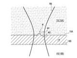
- a recording mark M (pit) is formed in which the center of the portion irradiated with the recording light RB has a convex shape from the recording layer 14 toward the adhesive layer 15A (intermediate layer 15).
- the recording mark M shown in FIG. 3 has a convex portion M1 at the center, and a ring-shaped concave portion M2 around the convex portion M1 toward the recording layer.
- the distance from the recording interface 18A (recording interface 18A before deformation) at the deepest portion of the recess M2 is smaller than the distance from the recording interface 18A (recording interface 18A before deformation) at the apex of the protrusion M1.
- the recording mark M as a whole can be said to be approximately convex.
- the recording mark has only a convex shape (convex portion M 1) and the concave portion M 2 is not formed around the convex shape depending on the recording conditions.
- the optical information recording medium 10 can record information with a convex shape from the recording layer 14 toward the pressure-sensitive adhesive layer 15A, so that it does not require energy enough to cause decomposition or phase change of the recording layer.
- the recording layer does not require a certain degree of absorption, so that information can be recorded with relatively small energy.
- information can be recorded with high sensitivity, and the recording layer 14 can be multilayered by reducing the recording light absorption rate per recording layer 14.
- the reading light OB is recorded at the recording interface 18A due to the difference in the refractive index of the recording layer 14 and the refractive index of the adhesive layer 15A. Is reflected. At this time, a difference occurs in the intensity of the reflected light at the recording interface 18A around the recording mark M and the recording mark M, so that the recording mark M can be detected by the difference in reflectance. Since the refractive index of the recording layer 14 does not change before and after recording, the reflection of the readout light OB does not occur inside the recording layer 14 but occurs only at the recording interface 18A, and the recording mark M is stabilized. Can be detected. For such optical detection, it is desirable that the convex portion M1 protrudes about 1 to 300 nm with respect to the interface (recording interface 18A) before being deformed.
- the recording mark M is formed with the concave portion M2 around the convex portion M1, when the reading light OB for reading the recording mark M is applied to the recording mark M, there is only the convex portion M1.
- the intensity distribution of the reflected light by the recording mark M is considered to change abruptly according to the distance from the center of the convex portion M1, and can be read with a high degree of modulation.
- the present invention includes not only the case where information is recorded by deforming the recording layer 14 into a convex shape, but also the case where information is recorded while being deformed into a concave shape.
- information can be recorded by deforming the recording layer 14 into a concave shape by increasing the energy of the recording light by increasing the peak power.
- the reading light OB is not reflected at the non-recording interface 18B. The deformation has no effect on playback.
- the fluidity of the polymer compound is improved by heating the recording layer 14 to a temperature near the glass transition temperature of the polymer compound, preferably higher than the glass transition temperature.
- the information recorded on the recording layer 14 can be erased by returning to the original plane after the interface 18 is not deformed by the surface tension.
- a method of irradiating a continuous wave laser so as to focus on the recording layer 14 can be used.
- By heating with a continuous wave laser it is possible to erase information in a continuous region in the recording layer 14 without unevenness.
- this continuous wave laser a laser used for reproducing information may be used, or another laser may be used. In any case, it is desirable to use a laser that emits light having a wavelength that allows one-photon absorption in the recording layer 14.
- the information recorded in all the recording layers 14 is heated by heating the entire optical information recording medium 10 to a temperature higher than the glass transition temperature of the polymer compound. Can be erased at once. Thereby, the entire information of the optical information recording medium 10 can be easily erased and initialized. In addition, information can be easily deleted even when the optical information recording medium 10 is discarded.
- the dye included in the recording layer 14 is a one-photon absorption dye
- information can be recorded with a laser beam having a small peak power.
- a semiconductor laser can be used as a laser beam having a small peak power
- the output of the laser beam can be easily adjusted.
- the coupling between the polymer compound and the one-photon absorption dye is caused by the combination of the polymer compound and the one-photon absorption dye, rather than the state where the one-photon absorption dye is dispersed in the polymer compound. Since a recording material having a high strength is used, high recording sensitivity can be provided as in the embodiments described later. Further, in the optical information recording medium 10, since the recording layer 14 includes a polymer compound to which a dye is bonded, the dye can be prevented from diffusing into the intermediate layer 15, and the optical information recording medium 10 has a long term. Stability can be improved.
- the optical information recording medium 10 is formed with a convex shape only at one interface (recording interface 18A) and no convex shape is formed at the other interface (non-recording interface 18B) by irradiation with recording light.
- the optical information recording medium of the present invention may be configured such that convex shapes directed to the intermediate layer as different information are formed on both interfaces of the recording layer.
- the intermediate layer adjacent to the recording layer can be realized as the pressure-sensitive adhesive layer 15A of the above-described embodiment.
- the thickness of each recording layer is preferably 2 ⁇ m or more, more preferably 5 ⁇ m or more, and further preferably 7 ⁇ m or more so that interlayer crosstalk does not occur.
- the upper limit of the thickness is not particularly limited. However, in order to increase the number of recording layers, the thinner one is desirable as long as interlayer crosstalk does not occur. For example, it is desirably 20 ⁇ m or less.
- the optical information recording medium 10 includes the guide layer 11A, the reflective layer 12, the spacer layer 13, the cover layer 16, and the hard coat layer 17 as shown in FIG.
- the presence or absence of each of these layers is arbitrary.
- the recording layer 14 may be only one layer, and in this case, the intermediate layer 15 is unnecessary.
- the optical information recording medium 10 may be accommodated in the cartridge 20.
- Example 1 the aforementioned compound A was used as a recording material.
- Compound A was synthesized by the following method.
- Comparative Example 1 In Comparative Example 1, the following compound B (monomer (1)) was used as a dye dispersed in the recording material. Compound B was synthesized by the synthesis method described above.
- Example 2 In Example 2, the following compound C was used as a recording material.
- Compound C was synthesized by the following method. 10.2 ml of propylene glycol monomethyl ether acetate is heated and stirred at 90 ° C. under a nitrogen atmosphere. Here, 0.5 g of monomer 4 described in paragraph [0306] of WO2008 / 123601, 12.6 g of benzyl methacrylate and Wako Pure Chemical Industries, Ltd. V-601 0.50 g of propylene glycol monomethyl ether acetate 10.2 ml solution was added dropwise over 2 hours. After stirring with heating at 90 ° C. for 4 hours, the mixture was allowed to cool to obtain a 40 mass% solution of compound C in propylene glycol monomethyl ether acetate.
- Comparative Example 2 In Comparative Example 2, the following compound D (monomer 4) was used as a dye dispersed in the recording material.
- Comparative Example 3 In Comparative Example 3, the following compound E was used as a recording material.
- Compound E was synthesized by the following method: (1) Synthesis of raw material compound M-1 3- [3-tert-butyl-5- (5-chloro-) obtained by hydrolysis and reduction of Tinuvin 109 manufactured by BASF 0.7 g of 2H-benzotriazol-2-yl) -4-hydroxyphenyl] propanol and 0.31 g of Karenz MOI manufactured by Showa Denko KK were dissolved in 5 ml of methyl ethyl ketone. Then, 0.02 g of dibutyltin laurate and 0.02 g of p-methoxyphenol were added and reacted at 75 ° C. for 4 hours, and then the solvent was distilled off to obtain 1.0 g of Compound M-1.
- Comparative Example 4 In Comparative Example 4, the following compound F was used as a dye dispersed in the recording material.
- Compound F was obtained by hydrolyzing BASF Tinuvin109 and then reducing it.
- the optical information recording medium produced in the experiment has a 20 ⁇ m first intermediate layer (recording layer support layer), a 1 ⁇ m recording layer, and a 20 ⁇ m second layer on a glass substrate having a thickness of 1 mm.
- An intermediate layer (adhesive layer) and a 67 ⁇ m cover layer are sequentially laminated.
- Second Formation of Recording Layer Compound A was diluted with PGMEA (propylene glycol monomethyl ether acetate) to prepare a coating solution having a solid content concentration of 13% by mass. This coating solution was applied onto the first intermediate layer by spin coating to a thickness of 1 ⁇ m to form a recording layer. The concentration of Compound A in the coating solution was adjusted so that the light absorption rate of the 1 ⁇ m recording layer was 8%.
- PGMEA propylene glycol monomethyl ether acetate
- Second intermediate layer (adhesive layer)
- a polyethylene terephthalate film coated with a silicone release layer on the surface was prepared as a release sheet, and an acrylic ester adhesive was applied thereon with a thickness of 20 ⁇ m by a bar coating method. Was applied to form an adhesive layer. Thereafter, the pressure-sensitive adhesive layer was bonded onto the recording layer, and the release sheet was removed to form an intermediate layer (pressure-sensitive adhesive layer).
- cover layer A 67 ⁇ m thick polycarbonate film (Panlite (registered trademark) film D-67 manufactured by Teijin Chemicals Ltd.) was bonded onto the intermediate layer (adhesive layer) to form a cover layer.
- Example 1 (1) Formation of first intermediate layer (recording layer support layer) The first intermediate layer (recording layer support layer) was formed by the same method as in Example 1 described above. (2) Formation of recording layer Compound B and polybenzyl methacrylate (PBMA, Sigma-Aldrich Mw-70,000) were dissolved in diethyl ketone at a mass ratio of 50:50, and the solid content concentration was 6% by mass. A liquid was prepared. This coating solution was applied onto the first intermediate layer by spin coating to a thickness of 1 ⁇ m to form a recording layer. The concentration of Compound B in the coating solution was adjusted so that the light absorption rate of the 1 ⁇ m recording layer was 8%. (3) Formation of 2nd intermediate
- Example 2 (1) Formation of first intermediate layer (recording layer support layer) The first intermediate layer (recording layer support layer) was formed by the same method as in Example 1 described above. (2) Formation of Recording Layer Compound C was diluted with PGMEA (propylene glycol monomethyl ether acetate) to prepare a coating solution having a solid content concentration of 13% by mass. This coating solution was applied onto the first intermediate layer by spin coating to a thickness of 1 ⁇ m to form a recording layer. The concentration of Compound C in the coating solution was adjusted so that the light absorption rate of the 1 ⁇ m recording layer was 8%. (3) Formation of 2nd intermediate
- Example 2 (1) Formation of first intermediate layer (recording layer support layer) The first intermediate layer (recording layer support layer) was formed by the same method as in Example 1 above. (2) Formation of recording layer Compound D and polybenzylmethacrylate (Sigma Aldrich Mw-70,000) are dissolved in methyl ethyl ketone at a mass ratio of 4:96 to prepare a coating solution having a solid content concentration of 9% by mass. did. This coating solution was applied onto the first intermediate layer by spin coating to a thickness of 1 ⁇ m to form a recording layer. The concentration of Compound D in the coating solution was adjusted so that the light absorption rate of the 1 ⁇ m recording layer was 8%. (3) Formation of 2nd intermediate
- Example 3 (1) Formation of first intermediate layer (recording layer support layer) The first intermediate layer (recording layer support layer) was formed by the same method as in Example 1 described above. (2) Formation of Recording Layer Compound E was diluted with PGMEA (propylene glycol monomethyl ether acetate) to prepare a coating solution having a solid content concentration of 13 wt%. This coating solution was applied onto the first intermediate layer by spin coating to a thickness of 1 ⁇ m to form a recording layer. The concentration of Compound E in the coating solution was adjusted so that the light absorption rate of the 1 ⁇ m recording layer was 8%. (3) Formation of 2nd intermediate
- first intermediate layer (recording layer support layer)
- the first intermediate layer (recording layer support layer) was formed by the same method as in Example 1 described above.
- This coating solution was applied onto the first intermediate layer by spin coating to a thickness of 1 ⁇ m to form a recording layer.
- the concentration of Compound F in the coating solution was adjusted so that the light absorption rate of the 1 ⁇ m recording layer was 8%.
- middle layer (adhesive layer) It formed with the method similar to the case of Example 1 mentioned above.
- the light absorption rate (%) was calculated from the obtained absorbance according to the following formula.
- Light absorption rate (1-10 ⁇ (absorbance) ) ⁇ 100
- the light absorptance was 8% in all Examples and Comparative Examples.
- the echo peak shift measurement was performed by the three-pulse photon echo measurement described in the above-mentioned reference [1]. Specifically, the time interval (Population Time, T) between the second pulse and the third pulse is fixed, and the induction is performed with respect to the interval between the first pulse and the second pulse (Coherent Time, ⁇ ). The signal intensities of photon echo and virtual echo are plotted. The echo peak shift measurement was performed by obtaining the time interval between the intensity peaks of the two echo signals and plotting half the value against T.
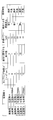
- Example 1 and Comparative Example 1 use the same dye, but Example 1 in which the dye is bonded to the polymer compound is different from Comparative Example 1 in which the dye is dispersed in the polymer compound. The coupling strength was large. Further, Example 2 and Comparative Example 2 also use the same dye, but Example 2 in which the dye is bonded to the polymer compound is compared with Comparative Example 2 in which the dye is dispersed in the polymer compound. The coupling strength was great. On the other hand, Comparative Example 3 and Comparative Example 4 use the same dye, and Comparative Example 3 in which the dye is bonded to the polymer compound is coupled with Comparative Example 4 in which the dye is dispersed in the polymer compound. The intensity was the same.
- Example 1 in which the coupling strength is larger than that in the case where the dye is bonded to the polymer compound is larger than that in the case of being dispersed in the polymer compound. It was possible to record with a smaller recording power. That is, the sensitivity was improved by the combination of the dye and the polymer compound. In Example 2, recording was possible with a smaller recording power than in Comparative Example 2, and an improvement in sensitivity was observed due to the combination of the dye and the polymer compound. On the other hand, Comparative Example 3 was able to record with the same recording power as Comparative Example 4, and no improvement in sensitivity was observed due to the combination of the dye and the polymer compound.
- each optical information recording medium was stored in an environment of 80 ° C. and 85% RH, and the intensity of reflected light from the interface between the recording layer and the intermediate layer (adhesive layer) after 100 hours was measured.
- a multilayer film thickness measuring instrument SI-TS10 manufactured by Keyence Corporation was used.
- Example 1 Example 2, and Comparative Example 3
- the reflected light intensity after 100 hours shows a high value of 90% with respect to the reflected light intensity before storage, and the change in reflected light intensity is small. confirmed.
- the optical information recording medium containing the polymer compound to which the dye is bound is less likely to diffuse into the intermediate layer even when stored at high temperature and humidity, and the storage stability is good. It means that there is.
- Comparative Example 1 Comparative Example 2 and Comparative Example 4
- the reflected light intensity after 100 hours is reduced to 50% or less with respect to the reflected light intensity before storage, and the change in reflected light intensity is large. confirmed.
Landscapes
- Chemical & Material Sciences (AREA)
- Organic Chemistry (AREA)
- Life Sciences & Earth Sciences (AREA)
- Engineering & Computer Science (AREA)
- Materials Engineering (AREA)
- Wood Science & Technology (AREA)
- Health & Medical Sciences (AREA)
- Chemical Kinetics & Catalysis (AREA)
- Medicinal Chemistry (AREA)
- Polymers & Plastics (AREA)
- Optical Record Carriers And Manufacture Thereof (AREA)
Abstract
Priority Applications (3)
| Application Number | Priority Date | Filing Date | Title |
|---|---|---|---|
| CN201480012971.6A CN105027205B (zh) | 2013-03-08 | 2014-01-22 | 光学信息记录介质 |
| JP2015504197A JP6064029B2 (ja) | 2013-03-08 | 2014-01-22 | 光情報記録媒体 |
| US14/845,492 US9406332B2 (en) | 2013-03-08 | 2015-09-04 | Optical information recording medium |
Applications Claiming Priority (2)
| Application Number | Priority Date | Filing Date | Title |
|---|---|---|---|
| JP2013-046153 | 2013-03-08 | ||
| JP2013046153 | 2013-03-08 |
Related Child Applications (1)
| Application Number | Title | Priority Date | Filing Date |
|---|---|---|---|
| US14/845,492 Continuation US9406332B2 (en) | 2013-03-08 | 2015-09-04 | Optical information recording medium |
Publications (1)
| Publication Number | Publication Date |
|---|---|
| WO2014136486A1 true WO2014136486A1 (fr) | 2014-09-12 |
Family
ID=51491013
Family Applications (1)
| Application Number | Title | Priority Date | Filing Date |
|---|---|---|---|
| PCT/JP2014/051305 WO2014136486A1 (fr) | 2013-03-08 | 2014-01-22 | Lentille zoom et dispositif d'imagerie équipé de celle-ci |
Country Status (4)
| Country | Link |
|---|---|
| US (1) | US9406332B2 (fr) |
| JP (1) | JP6064029B2 (fr) |
| CN (1) | CN105027205B (fr) |
| WO (1) | WO2014136486A1 (fr) |
Cited By (1)
| Publication number | Priority date | Publication date | Assignee | Title |
|---|---|---|---|---|
| US12062387B2 (en) | 2020-11-16 | 2024-08-13 | Huawei Technologies Co., Ltd. | Optical storage medium, method for preparing optical storage medium, and system |
Families Citing this family (1)
| Publication number | Priority date | Publication date | Assignee | Title |
|---|---|---|---|---|
| WO2014192522A1 (fr) * | 2013-05-27 | 2014-12-04 | 富士フイルム株式会社 | Matériau d'enregistrement et support optique d'enregistrement d'informations |
Citations (5)
| Publication number | Priority date | Publication date | Assignee | Title |
|---|---|---|---|---|
| JPH10329419A (ja) * | 1997-05-28 | 1998-12-15 | Fuji Photo Film Co Ltd | テープ状光学的情報記録媒体 |
| JP2000076729A (ja) * | 1998-08-31 | 2000-03-14 | Fuji Photo Film Co Ltd | 磁性層と光記録層を有する記録媒体 |
| JP2004095142A (ja) * | 2002-06-18 | 2004-03-25 | Ricoh Co Ltd | 光記録媒体及びその製造方法 |
| JP2008516293A (ja) * | 2004-10-13 | 2008-05-15 | ゼネラル・エレクトリック・カンパニイ | ホログラフィック記憶媒体 |
| JP2012089195A (ja) * | 2010-10-19 | 2012-05-10 | Fujifilm Corp | 光情報記録媒体 |
Family Cites Families (15)
| Publication number | Priority date | Publication date | Assignee | Title |
|---|---|---|---|---|
| US4852075A (en) | 1983-08-22 | 1989-07-25 | Optical Data, Inc. | Erasable optical data storage medium and method and apparatus for recording data on the medium |
| US4912696A (en) | 1983-08-22 | 1990-03-27 | Optical Data, Inc. | Erasable optical data storage medium and method and apparatus for recording data on the medium |
| US4719615A (en) | 1983-08-22 | 1988-01-12 | Optical Data, Inc. | Erasable optical data storage medium |
| JPH07118090B2 (ja) | 1983-08-22 | 1995-12-18 | オプティカル デ−タ インコ−ポレ−テッド | 消去可能光学デ−タ記憶媒体および該媒体のデ−タ記録方法 |
| JP2771231B2 (ja) | 1989-03-27 | 1998-07-02 | 帝人株式会社 | 消去可能な光学情報記録媒体および情報の記録・消去方法 |
| US5215800A (en) | 1989-01-17 | 1993-06-01 | Teijin Limited | Erasable optical recording medium and method for writing, reading and/or erasing thereof |
| CN1972810A (zh) * | 2004-06-23 | 2007-05-30 | 富士胶片株式会社 | 新型氧杂菁染料化合物和光学信息记录介质 |
| JP5396343B2 (ja) * | 2010-07-13 | 2014-01-22 | 富士フイルム株式会社 | 光情報記録媒体およびその製造方法 |
| JP5406134B2 (ja) * | 2010-07-13 | 2014-02-05 | 富士フイルム株式会社 | 光情報記録媒体およびその製造方法 |
| JP2012022734A (ja) * | 2010-07-13 | 2012-02-02 | Fujifilm Corp | 光情報記録媒体および光情報記録方法 |
| JP5357114B2 (ja) * | 2010-07-13 | 2013-12-04 | 富士フイルム株式会社 | 光情報記録媒体 |
| JP5553718B2 (ja) * | 2010-09-17 | 2014-07-16 | 富士フイルム株式会社 | 光情報記録媒体 |
| JP5476329B2 (ja) * | 2011-03-25 | 2014-04-23 | 富士フイルム株式会社 | 光情報記録媒体 |
| JP5603276B2 (ja) * | 2011-03-28 | 2014-10-08 | 富士フイルム株式会社 | 光情報記録媒体 |
| JP5705049B2 (ja) * | 2011-07-13 | 2015-04-22 | 富士フイルム株式会社 | 多層構造シートとその製造方法、光情報記録媒体および多層構造シートを用いた光情報記録媒体の製造方法 |
-
2014
- 2014-01-22 WO PCT/JP2014/051305 patent/WO2014136486A1/fr active Application Filing
- 2014-01-22 CN CN201480012971.6A patent/CN105027205B/zh active Active
- 2014-01-22 JP JP2015504197A patent/JP6064029B2/ja not_active Expired - Fee Related
-
2015
- 2015-09-04 US US14/845,492 patent/US9406332B2/en not_active Expired - Fee Related
Patent Citations (5)
| Publication number | Priority date | Publication date | Assignee | Title |
|---|---|---|---|---|
| JPH10329419A (ja) * | 1997-05-28 | 1998-12-15 | Fuji Photo Film Co Ltd | テープ状光学的情報記録媒体 |
| JP2000076729A (ja) * | 1998-08-31 | 2000-03-14 | Fuji Photo Film Co Ltd | 磁性層と光記録層を有する記録媒体 |
| JP2004095142A (ja) * | 2002-06-18 | 2004-03-25 | Ricoh Co Ltd | 光記録媒体及びその製造方法 |
| JP2008516293A (ja) * | 2004-10-13 | 2008-05-15 | ゼネラル・エレクトリック・カンパニイ | ホログラフィック記憶媒体 |
| JP2012089195A (ja) * | 2010-10-19 | 2012-05-10 | Fujifilm Corp | 光情報記録媒体 |
Cited By (1)
| Publication number | Priority date | Publication date | Assignee | Title |
|---|---|---|---|---|
| US12062387B2 (en) | 2020-11-16 | 2024-08-13 | Huawei Technologies Co., Ltd. | Optical storage medium, method for preparing optical storage medium, and system |
Also Published As
| Publication number | Publication date |
|---|---|
| JP6064029B2 (ja) | 2017-01-18 |
| CN105027205B (zh) | 2018-11-27 |
| JPWO2014136486A1 (ja) | 2017-02-09 |
| US9406332B2 (en) | 2016-08-02 |
| US20150380042A1 (en) | 2015-12-31 |
| CN105027205A (zh) | 2015-11-04 |
Similar Documents
| Publication | Publication Date | Title |
|---|---|---|
| US8644126B2 (en) | Optical information recording medium and method for manufacturing same | |
| JP5476329B2 (ja) | 光情報記録媒体 | |
| JP5553723B2 (ja) | 光情報記録媒体 | |
| JP5705049B2 (ja) | 多層構造シートとその製造方法、光情報記録媒体および多層構造シートを用いた光情報記録媒体の製造方法 | |
| JP5357114B2 (ja) | 光情報記録媒体 | |
| US8701133B2 (en) | Optical information recording medium and method for manufacturing same | |
| WO2012008290A1 (fr) | Procédé d'enregistrement et de reproduction d'un support d'enregistrement optique d'informations | |
| EP1635340A2 (fr) | Support d'enregistrement optique | |
| JP6064029B2 (ja) | 光情報記録媒体 | |
| JP5528416B2 (ja) | 光情報記録媒体およびその製造方法ならびに光情報記録媒体の記録方法 | |
| JP6154898B2 (ja) | 光情報記録媒体 | |
| WO2014050443A1 (fr) | Support d'enregistrement d'informations optiques et son procédé de fabrication | |
| JP2006085763A (ja) | 光記録媒体 | |
| WO2012035977A1 (fr) | Support d'enregistrement d'informations optiques | |
| JP4698357B2 (ja) | 光記録用組成物及びこれを用いた光記録媒体 | |
| JP2012089194A (ja) | 光情報記録媒体の製造方法 | |
| JP2007273026A (ja) | 光記録用組成物、並びに、該光記録用組成物を用いた重合体、記録層、及び光記録媒体 | |
| JP2006092600A (ja) | 光記録媒体 | |
| JP2007206460A (ja) | 光記録用組成物及びその製造方法、並びに光記録媒体 | |
| JP2009075278A (ja) | 光記録用組成物およびホログラフィック記録媒体 |
Legal Events
| Date | Code | Title | Description |
|---|---|---|---|
| WWE | Wipo information: entry into national phase |
Ref document number: 201480012971.6 Country of ref document: CN |
|
| 121 | Ep: the epo has been informed by wipo that ep was designated in this application |
Ref document number: 14760305 Country of ref document: EP Kind code of ref document: A1 |
|
| ENP | Entry into the national phase |
Ref document number: 2015504197 Country of ref document: JP Kind code of ref document: A |
|
| NENP | Non-entry into the national phase |
Ref country code: DE |
|
| 122 | Ep: pct application non-entry in european phase |
Ref document number: 14760305 Country of ref document: EP Kind code of ref document: A1 |