WO2014133094A1 - Dispositif de diagnostic par ultrasons - Google Patents
Dispositif de diagnostic par ultrasons Download PDFInfo
- Publication number
- WO2014133094A1 WO2014133094A1 PCT/JP2014/054926 JP2014054926W WO2014133094A1 WO 2014133094 A1 WO2014133094 A1 WO 2014133094A1 JP 2014054926 W JP2014054926 W JP 2014054926W WO 2014133094 A1 WO2014133094 A1 WO 2014133094A1
- Authority
- WO
- WIPO (PCT)
- Prior art keywords
- image
- ultrasonic
- series
- unit
- images
- Prior art date
Links
Images


Classifications
-
- A—HUMAN NECESSITIES
- A61—MEDICAL OR VETERINARY SCIENCE; HYGIENE
- A61B—DIAGNOSIS; SURGERY; IDENTIFICATION
- A61B8/00—Diagnosis using ultrasonic, sonic or infrasonic waves
- A61B8/46—Ultrasonic, sonic or infrasonic diagnostic devices with special arrangements for interfacing with the operator or the patient
- A61B8/461—Displaying means of special interest
- A61B8/463—Displaying means of special interest characterised by displaying multiple images or images and diagnostic data on one display
-
- A—HUMAN NECESSITIES
- A61—MEDICAL OR VETERINARY SCIENCE; HYGIENE
- A61B—DIAGNOSIS; SURGERY; IDENTIFICATION
- A61B8/00—Diagnosis using ultrasonic, sonic or infrasonic waves
- A61B8/06—Measuring blood flow
-
- A—HUMAN NECESSITIES
- A61—MEDICAL OR VETERINARY SCIENCE; HYGIENE
- A61B—DIAGNOSIS; SURGERY; IDENTIFICATION
- A61B8/00—Diagnosis using ultrasonic, sonic or infrasonic waves
- A61B8/13—Tomography
- A61B8/14—Echo-tomography
-
- A—HUMAN NECESSITIES
- A61—MEDICAL OR VETERINARY SCIENCE; HYGIENE
- A61B—DIAGNOSIS; SURGERY; IDENTIFICATION
- A61B8/00—Diagnosis using ultrasonic, sonic or infrasonic waves
- A61B8/48—Diagnostic techniques
- A61B8/483—Diagnostic techniques involving the acquisition of a 3D volume of data
-
- A—HUMAN NECESSITIES
- A61—MEDICAL OR VETERINARY SCIENCE; HYGIENE
- A61B—DIAGNOSIS; SURGERY; IDENTIFICATION
- A61B8/00—Diagnosis using ultrasonic, sonic or infrasonic waves
- A61B8/52—Devices using data or image processing specially adapted for diagnosis using ultrasonic, sonic or infrasonic waves
- A61B8/5207—Devices using data or image processing specially adapted for diagnosis using ultrasonic, sonic or infrasonic waves involving processing of raw data to produce diagnostic data, e.g. for generating an image
-
- A—HUMAN NECESSITIES
- A61—MEDICAL OR VETERINARY SCIENCE; HYGIENE
- A61B—DIAGNOSIS; SURGERY; IDENTIFICATION
- A61B8/00—Diagnosis using ultrasonic, sonic or infrasonic waves
- A61B8/52—Devices using data or image processing specially adapted for diagnosis using ultrasonic, sonic or infrasonic waves
- A61B8/5215—Devices using data or image processing specially adapted for diagnosis using ultrasonic, sonic or infrasonic waves involving processing of medical diagnostic data
- A61B8/5223—Devices using data or image processing specially adapted for diagnosis using ultrasonic, sonic or infrasonic waves involving processing of medical diagnostic data for extracting a diagnostic or physiological parameter from medical diagnostic data
-
- A—HUMAN NECESSITIES
- A61—MEDICAL OR VETERINARY SCIENCE; HYGIENE
- A61B—DIAGNOSIS; SURGERY; IDENTIFICATION
- A61B8/00—Diagnosis using ultrasonic, sonic or infrasonic waves
- A61B8/52—Devices using data or image processing specially adapted for diagnosis using ultrasonic, sonic or infrasonic waves
- A61B8/5269—Devices using data or image processing specially adapted for diagnosis using ultrasonic, sonic or infrasonic waves involving detection or reduction of artifacts
- A61B8/5276—Devices using data or image processing specially adapted for diagnosis using ultrasonic, sonic or infrasonic waves involving detection or reduction of artifacts due to motion
-
- A—HUMAN NECESSITIES
- A61—MEDICAL OR VETERINARY SCIENCE; HYGIENE
- A61B—DIAGNOSIS; SURGERY; IDENTIFICATION
- A61B8/00—Diagnosis using ultrasonic, sonic or infrasonic waves
- A61B8/52—Devices using data or image processing specially adapted for diagnosis using ultrasonic, sonic or infrasonic waves
- A61B8/5292—Devices using data or image processing specially adapted for diagnosis using ultrasonic, sonic or infrasonic waves using additional data, e.g. patient information, image labeling, acquisition parameters
-
- G—PHYSICS
- G06—COMPUTING; CALCULATING OR COUNTING
- G06T—IMAGE DATA PROCESSING OR GENERATION, IN GENERAL
- G06T7/00—Image analysis
- G06T7/0002—Inspection of images, e.g. flaw detection
- G06T7/0012—Biomedical image inspection
-
- G—PHYSICS
- G16—INFORMATION AND COMMUNICATION TECHNOLOGY [ICT] SPECIALLY ADAPTED FOR SPECIFIC APPLICATION FIELDS
- G16H—HEALTHCARE INFORMATICS, i.e. INFORMATION AND COMMUNICATION TECHNOLOGY [ICT] SPECIALLY ADAPTED FOR THE HANDLING OR PROCESSING OF MEDICAL OR HEALTHCARE DATA
- G16H50/00—ICT specially adapted for medical diagnosis, medical simulation or medical data mining; ICT specially adapted for detecting, monitoring or modelling epidemics or pandemics
- G16H50/30—ICT specially adapted for medical diagnosis, medical simulation or medical data mining; ICT specially adapted for detecting, monitoring or modelling epidemics or pandemics for calculating health indices; for individual health risk assessment
-
- A—HUMAN NECESSITIES
- A61—MEDICAL OR VETERINARY SCIENCE; HYGIENE
- A61B—DIAGNOSIS; SURGERY; IDENTIFICATION
- A61B8/00—Diagnosis using ultrasonic, sonic or infrasonic waves
- A61B8/08—Detecting organic movements or changes, e.g. tumours, cysts, swellings
-
- A—HUMAN NECESSITIES
- A61—MEDICAL OR VETERINARY SCIENCE; HYGIENE
- A61B—DIAGNOSIS; SURGERY; IDENTIFICATION
- A61B8/00—Diagnosis using ultrasonic, sonic or infrasonic waves
- A61B8/48—Diagnostic techniques
- A61B8/488—Diagnostic techniques involving Doppler signals
-
- Y—GENERAL TAGGING OF NEW TECHNOLOGICAL DEVELOPMENTS; GENERAL TAGGING OF CROSS-SECTIONAL TECHNOLOGIES SPANNING OVER SEVERAL SECTIONS OF THE IPC; TECHNICAL SUBJECTS COVERED BY FORMER USPC CROSS-REFERENCE ART COLLECTIONS [XRACs] AND DIGESTS
- Y02—TECHNOLOGIES OR APPLICATIONS FOR MITIGATION OR ADAPTATION AGAINST CLIMATE CHANGE
- Y02A—TECHNOLOGIES FOR ADAPTATION TO CLIMATE CHANGE
- Y02A90/00—Technologies having an indirect contribution to adaptation to climate change
- Y02A90/10—Information and communication technologies [ICT] supporting adaptation to climate change, e.g. for weather forecasting or climate simulation
Definitions
- Embodiments of the present invention relate to an ultrasonic diagnostic apparatus that images a scanned region in a subject.
- an ultrasonic diagnostic apparatus performs an operation for generating a Doppler waveform or updating a Doppler waveform and an input of a freeze operation (hereinafter referred to as a predetermined operation), for example, using a pulse Doppler method. It has a function to collect waveforms. At this time, the update of the color Doppler image is stopped. In addition, the ultrasonic diagnostic apparatus stores the stopped color Doppler image after collecting the Doppler waveform.
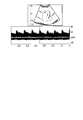
- the stopped color Doppler image may be an image that is not optimal for the operator as shown in FIG. This is because, for example, the breathing and pulsation of the subject, the shaking of the hand of the operator holding the ultrasonic probe, and the like affect the color Doppler image depending on the execution timing of a predetermined operation. At this time, the operator can manually select an optimal color Doppler image for storage. However, manual color Doppler image selection is cumbersome for the operator and may reduce inspection efficiency. In addition, the stopped color Doppler image may be stored in a state unsuitable for recording.
- the purpose is to provide an ultrasonic diagnostic apparatus capable of selecting and storing a color Doppler image optimal for recording.
- the ultrasonic diagnostic apparatus includes a transmission / reception unit that transmits / receives ultrasonic waves to / from a subject via a piezoelectric vibrator, and a color Doppler image and a Doppler waveform image based on an output from the transmission / reception unit.
- An ultrasonic image generation unit that generates a series of ultrasonic images, a specific information generation unit that generates predetermined specific information in each of the series of ultrasonic images, and a predetermined during display of the series of ultrasonic images
- the image processing apparatus includes a selection unit that selects a color Doppler image from the series of ultrasonic images based on the specific information, and a storage unit that stores the selected color Doppler image.
- FIG. 1 is a configuration diagram showing the configuration of the ultrasonic diagnostic apparatus according to the first embodiment.
- FIG. 2 is a diagram illustrating an example of a list of specific information generated by the specific information generation unit according to the first embodiment.
- FIG. 3 is a diagram illustrating a maximum flow velocity time, an R wave time, and a time interval in the electrocardiogram displayed together with the Doppler waveform image according to the first embodiment.
- FIG. 4 is a diagram illustrating a measurement cursor setting time, an R-wave time, and a time interval in the electrocardiogram displayed together with the triplex display according to the first embodiment.
- FIG. 5 is a diagram illustrating a selected color Doppler image together with a Doppler waveform image according to the first embodiment.
- FIG. 6 is a flowchart illustrating an example of a procedure of color Doppler image selection processing according to the first embodiment.
- FIG. 7 is a configuration diagram showing the configuration of the ultrasonic diagnostic apparatus according to the second embodiment.
- FIG. 8 is a flowchart illustrating an example of a procedure of color Doppler image index selection processing.
- FIG. 9 is a diagram illustrating an example of a color Doppler image that is not optimal for recording in the related art.
- FIG. 10 is a flowchart illustrating an example of a procedure of color Doppler image selection processing according to the second modification of the first embodiment.
- FIG. 11 is a flowchart illustrating an example of a procedure of color Doppler image selection processing according to the third modification of the first embodiment.
- FIG. 1 is a configuration diagram showing a configuration of an ultrasonic diagnostic apparatus 1 according to the first embodiment.
- the ultrasonic diagnostic apparatus 1 is connected to the ultrasonic probe 11, the apparatus main body 13, the display unit 15, and the apparatus main body 13 and receives various instructions / commands / information from the operator. And an input unit 17 for capturing.
- the ultrasonic diagnostic apparatus 1 may be connected to a biological signal measuring unit 19 represented by an electrocardiograph, a heart sound meter, a pulse wave meter, and a network through an interface unit 37.
- the biological signal measuring unit 19 measures a biological signal waveform related to the subject.
- the biological signal measuring unit 19 outputs the measured biological signal waveform to the apparatus main body 13 via the interface unit 37 described later.
- the biological signal measurement unit 19 is, for example, an electrocardiograph, a heart sound meter, a pulse wave meter, or the like.
- the ultrasonic probe 11 has a plurality of piezoelectric vibrators, a matching layer, and a backing material provided on the back side of the plurality of piezoelectric vibrators.
- the plurality of piezoelectric vibrators are acoustic / electric reversible conversion elements such as piezoelectric ceramics.
- the plurality of piezoelectric vibrators are arranged in parallel and are provided at the tip of the ultrasonic probe 11. In the following description, it is assumed that one piezoelectric vibrator constitutes one channel.
- the piezoelectric vibrator generates an ultrasonic wave in response to a drive signal supplied from a transmitter / receiver 21 described later.
- the transmitted ultrasonic wave (hereinafter referred to as a transmitted ultrasonic wave) is reflected by a discontinuous surface of acoustic impedance in the living tissue in the subject. Is done.
- the piezoelectric vibrator receives the reflected ultrasonic wave and generates an echo signal.
- the amplitude of the echo signal depends on the difference in acoustic impedance with the discontinuous surface regarding the reflection of the ultrasonic wave as a boundary.
- the frequency of the echo signal when the transmitted ultrasonic wave is reflected by the moving blood flow and the surface of the heart wall, etc. is transmitted by the Doppler effect. It shifts depending on the velocity component of the direction.
- the ultrasonic probe 11 will be described as a mechanical four-dimensional probe that performs three-dimensional scanning by swinging a one-dimensional array in a direction orthogonal to the arrangement direction of a plurality of transducers.
- the ultrasonic probe 11 is not limited to a mechanical four-dimensional probe, and may be a two-dimensional array probe. That is, the ultrasonic probe 11 is a probe that can acquire a three-dimensional echo signal.
- the matching layer is provided on the ultrasonic radiation surface side of the plurality of piezoelectric vibrators in order to efficiently transmit / receive ultrasonic waves to / from the subject P.
- the backing material prevents the propagation of ultrasonic waves to the back of the piezoelectric vibrator.
- the apparatus body 13 includes a transmission / reception unit 21, a B-mode processing unit 23, a Doppler processing unit 25, an ultrasonic image generation unit 27, a specific information generation unit 29, a selection unit 31, a storage unit 33, and an image composition.
- a unit 35, an interface unit 37, and a control processor (central processing unit: hereinafter referred to as CPU) 39 are included.
- the transmission / reception unit 21 supplies a drive signal to each of the plurality of piezoelectric vibrators in the ultrasonic probe 11 under the control of the CPU 39 described later.
- the transmission / reception unit 21 generates a reception signal based on the reception echo signal generated by each piezoelectric vibrator.
- the transmission / reception unit 21 includes a pulse generator (not shown), a transmission delay circuit, a pulsar circuit, a preamplifier, and an analog-to-digital (hereinafter referred to as A / D) converter.
- a reception delay circuit and an adder are analog-to-digital converters.
- the pulse generator repeatedly generates rate pulses for forming transmission ultrasonic waves at a predetermined rate frequency frHz (cycle: 1 / fr second).
- the generated rate pulse is distributed to the number of channels and sent to the transmission delay circuit.
- the transmission delay circuit provides each rate pulse with a delay time (hereinafter referred to as a transmission delay time) necessary for converging transmission ultrasonic waves into a beam and determining transmission directivity for each of a plurality of channels. .
- the transmission direction or transmission delay time of transmission ultrasonic waves (hereinafter referred to as a transmission delay pattern) is stored in the storage unit 33 described later.
- the transmission delay pattern stored in the storage unit 33 is referred to when an ultrasonic wave is transmitted by the CPU 39 described later.
- the pulser circuit applies a voltage pulse (drive signal) to each piezoelectric vibrator of the ultrasonic probe 11 at a timing based on this rate pulse. Thereby, an ultrasonic beam is transmitted to the subject.
- the preamplifier amplifies the echo signal from the subject P captured via the ultrasonic probe 11 for each channel.
- the A / D converter converts the amplified received echo signal into a digital signal.
- the reception delay circuit gives a delay time (hereinafter referred to as reception delay time) necessary for determining the reception directivity to the reception echo signal converted into the digital signal.
- reception delay time The reception direction or reception delay time of the echo signal (hereinafter referred to as reception delay pattern) is stored in the storage unit 33 described later.
- reception delay pattern stored in the storage unit 33 is referred to when receiving ultrasonic waves by the CPU 39 described later.
- the adder adds a plurality of echo signals given delay times.
- the transmission / reception unit 21 generates a reception signal (also referred to as an RF (radiofrequency) signal) in which the reflection component from the direction according to the reception directivity is emphasized.
- the overall directivity of ultrasonic transmission / reception is determined by the transmission directivity and the reception directivity. This total directivity determines the ultrasonic beam (so-called “ultrasonic scanning line”).
- the B mode processing unit 23 generates B mode data based on the reception signal output from the transmission / reception unit 21.
- the B mode processing unit 23 may generate volume data related to the B mode based on the B mode data.
- the B-mode processing unit includes an envelope detector, a logarithmic converter, and the like not shown.
- the envelope detector performs envelope detection on the reception signal output from the transmission / reception unit 21.
- the envelope detector outputs the envelope-detected signal to a logarithmic converter described later.
- the logarithmic converter relatively emphasizes a weak signal by logarithmically converting the envelope-detected signal.
- the B mode processing unit 23 generates a signal value (B mode data) for each depth in each scanning line based on the signal emphasized by the logarithmic converter.
- the B-mode processing unit 23 has a plurality of signals arranged in association with the azimuth direction, the elevation direction, and the depth direction (hereinafter referred to as the range direction) in the scanned region.
- Volume data may be generated based on the value.
- the range direction is the depth direction on the scanning line.
- the azimuth direction is, for example, an electronic scanning direction along the arrangement direction of the one-dimensional piezoelectric vibrators.
- the elevation direction is the mechanical oscillation direction of the one-dimensional piezoelectric vibrator.
- the volume data may be data in which a plurality of pixel values or a plurality of luminance values are arranged in association with the azimuth direction, the elevation direction, and the range direction along the scanning line.
- the Doppler processing unit 25 generates Doppler data based on the received signal output from the transmission / reception unit 21. Note that the Doppler processing unit 25 may generate volume data related to the Doppler mode based on the Doppler data.
- the Doppler processing unit 25 includes a mixer (not shown), a low-pass filter (Low Pass Filter: hereinafter referred to as LPF), a speed / dispersion / Power arithmetic device, and the like.
- LPF Low Pass Filter
- the mixer multiplies the reception signal output from the transmission / reception unit 21 by a reference signal having the same frequency f0 as the transmission frequency.
- a signal having a component of Doppler shift frequency fd and a signal having a frequency component of (2f0 + fd) are obtained.
- the LPF removes a signal having a high frequency component (2f0 + fd) from signals having two types of frequency components from the mixer.
- the Doppler processing unit 25 generates a Doppler signal having a Doppler shift frequency fd component by removing a signal having a high frequency component (2f0 + fd).
- the Doppler processing unit 25 may use a quadrature detection method in order to generate a Doppler signal.
- the received signal (RF signal) is quadrature detected and converted to an IQ signal.
- the Doppler processing unit 25 generates a Doppler signal having a component of the Doppler shift frequency fd by performing a complex Fourier transform on the IQ signal.
- the Doppler signal is, for example, a Doppler component due to blood flow, tissue, or contrast medium.
- the speed / dispersion / Power calculation device includes an MTI (Moving Target Indicator) filter, an LPF filter, an autocorrelation calculator, etc., not shown.
- a cross-correlation calculator may be provided instead of the autocorrelation calculator.
- the MTI filter removes Doppler components (clutter components) caused by respiratory movement or pulsatile movement of the organ from the generated Doppler signal.
- the MTI filter is used to extract a Doppler component related to blood flow (hereinafter referred to as a blood flow Doppler component) from the Doppler signal.
- the LPF is used to extract a Doppler component related to tissue movement (hereinafter referred to as a tissue Doppler component) from the Doppler signal.
- the autocorrelation calculator calculates autocorrelation values for blood flow Doppler components and tissue Doppler components. Based on the calculated autocorrelation value, the autocorrelation calculator calculates an average velocity value, a variance value, a reflection intensity (power) of the Doppler signal, and the like of the blood flow and the tissue.
- the velocity / dispersion / power calculation device generates color Doppler data at each position in the scanned region based on the blood flow and tissue average velocity values based on a plurality of Doppler signals, the variance value, the Doppler signal reflection intensity, and the like. .
- Doppler signals and color Doppler data are collectively referred to as Doppler data.
- the ultrasonic image generation unit 27 includes a digital scan converter (Digital Scan Converter: hereinafter referred to as DSC) and an image memory (not shown).
- the ultrasonic image generation unit 27 performs a coordinate conversion process (resampling) on the DSC.
- the coordinate conversion process is, for example, a process of converting an ultrasonic scan scanning line signal sequence composed of B-mode data and Doppler data into a scanning line signal sequence of a general video format represented by a television or the like.
- the ultrasonic image generation unit 27 generates an ultrasonic image as a display image by coordinate conversion processing. Specifically, the ultrasonic image generation unit 27 generates a B-mode image based on the B-mode data.
- the ultrasonic image generation unit 27 generates a color blood flow image such as an average velocity image and a dispersion image, a power blood flow image indicating the reflection intensity of the Doppler signal, and the like based on the color Doppler data.
- the ultrasonic image generator 27 generates a superimposed image in which a color blood flow image is superimposed on a B-mode image.
- the ultrasonic image generation unit 27 generates a superimposed image in which the power blood flow image is superimposed on the B-mode image.
- a superimposed image obtained by superimposing a color blood flow image on a B-mode image and a superimposed image obtained by superimposing a power blood flow image on a B-mode image are collectively referred to as a color Doppler image.
- the ultrasonic image generation unit 27 generates a Doppler waveform image indicating the Doppler waveform based on the Doppler signal.
- the ultrasonic image generation unit 27 generates an ultrasonic image having a color Doppler image and a Doppler waveform image. Note that the ultrasonic image may include a B-mode image and a Doppler waveform image.
- the ultrasonic image generation unit 27 generates a series of ultrasonic images in time series until a predetermined operation relating to collection of Doppler waveforms is executed via the input unit 17 described later.
- the ultrasonic image generation unit 27 can generate a series of ultrasonic images again after collecting Doppler waveforms.
- the ultrasonic image generation unit 27 outputs the generated ultrasonic image to an image synthesis unit 35 described later and an image memory (not shown).
- the image memory stores data (hereinafter referred to as image data) corresponding to the generated ultrasonic image.
- the image data stored in the image memory is read according to an operator instruction via the input unit 17 described later.
- the image memory is, for example, a memory that stores an ultrasound image corresponding to a series of frames immediately before freezing.
- An ultrasonic moving image is displayed on the display unit 15 by continuously displaying the images stored in the image memory on the display unit 15 (cine display).
- the image memory may store a plurality of ultrasonic images included in a predetermined range of time width centered on a time corresponding to a color Doppler image selected by the selection unit 31 described later.
- the ultrasonic moving image is displayed on the display unit 15 by continuously displaying (cine display) a plurality of ultrasonic images included in the time width of the predetermined range.
- the specific information generating unit 29 generates predetermined specific information related to the color Doppler image suitable for recording based on the ultrasonic image.
- the predetermined specific information includes, for example, information on color blood flow images and power blood flow images (hereinafter referred to as color image information), information on B mode images (hereinafter referred to as B mode image information), and Doppler waveform images.
- the information is at least one of information related to blood flow velocity (hereinafter referred to as blood flow velocity information) and information related to a periodic biological signal waveform corresponding to a Doppler waveform (biological information).
- the biological signal waveform is a periodic waveform associated with generation of a Doppler waveform such as an electrocardiogram waveform, a heart waveform, a pulse waveform, and a color Doppler image.
- a Doppler waveform such as an electrocardiogram waveform, a heart waveform, a pulse waveform, and a color Doppler image.
- the biological signal waveform is an electrocardiographic waveform.
- the specific information generation unit 29 uses, as color image information, the number of pixels in the color region of the color blood flow image and the power blood flow image (hereinafter referred to as the number of color pixels) for each series of ultrasonic images. Count.
- the specific information generation unit 29 outputs the generated color image information (the number of color pixels) to the selection unit 31 described later.
- the specific information generating unit 29 generates a difference absolute value image indicating an absolute value of a difference between two temporally adjacent B-mode images in a series of ultrasonic images.
- the specific information generation unit 29 detects the motion of the B-mode image in the scanned region using the difference absolute value image.
- the motion of the B-mode image is, for example, a motion vector at each point in the scanned region. That is, the specific information generating unit 29 generates a motion vector field indicating a motion vector at each point in the scanned region.
- the specific information generation unit 29 may detect a motion vector by correlation matching using two B-mode images that are temporally adjacent.
- the specific information generation part 29 produces
- the specific information generation unit 29 outputs the generated B-mode image information (motion vector field) to the selection unit 31 described later.
- the specific information generation unit 29 determines the maximum flow velocity time corresponding to the maximum flow velocity value based on the Doppler waveform in the Doppler waveform image as the blood flow velocity information. Specifically, the specific information generating unit 29 specifies the maximum flow velocity value of the blood flow based on the Doppler waveform. The specific information generation unit 29 determines the maximum flow velocity time based on the identified maximum flow velocity value. The specific information generation unit 29 outputs the determined maximum flow velocity time to the selection unit 31 described later. The specific information generation unit 29 generates, as the blood flow velocity information, an average blood flow velocity value near the sample gate set on the color blood flow image of the series of ultrasonic images for each series of ultrasonic images. May be.
- the specific information generation unit 29 determines the measurement cursor setting time (hereinafter referred to as measurement cursor setting time) based on the position of the measurement cursor set in the Doppler waveform in the Doppler waveform image.
- the measurement cursor is a cursor for setting the position for measuring the blood flow velocity on the Doppler waveform of the Doppler waveform image displayed on the display unit 15 via the input unit 17. That is, the blood flow velocity is measured at the time corresponding to the position set on the Doppler waveform.
- FIG. 2 is a diagram showing an example of a list of specific information generated by the specific information generating unit 29.
- the specific information generation unit 29 may generate at least one specific information among the plurality of items of specific information shown in FIG.
- the selection unit 31 performs recording from a plurality of color Doppler images in a series of ultrasonic images based on specific information, triggered by a predetermined operation via the input unit 17 to be described later, during display of the series of ultrasonic images. Select a color Doppler image suitable for The selection unit 31 outputs the selected color Doppler image to the display unit 15 and the storage unit 33.
- the predetermined operation is, for example, an input operation via the input unit 17 such as a Doppler waveform update operation or a freeze operation.
- the predetermined operation may be a press of a Doppler mode start button corresponding to an execution instruction for pulse Doppler or an execution instruction for continuous wave Doppler.
- the selection unit 31 selects a color Doppler image having the maximum number of color pixels or the maximum average flow velocity value as a color Doppler image suitable for recording from a series of ultrasonic images.
- the selection unit 31 may select a color Doppler image having a B-mode image with the smallest motion vector field from a series of ultrasonic images.
- the series of ultrasonic images to be selected may be all ultrasonic images generated for the subject. Further, the series of ultrasonic images to be selected may be a plurality of ultrasonic images in a range preset by a predetermined phase in the electrocardiographic waveform.
- the selection unit 31 calculates the maximum flow velocity time from the series of ultrasonic images. It is also possible to select a color Doppler image corresponding to.
- the selection unit 31 is based on the time interval from the R wave time of the electrocardiogram waveform immediately before the maximum flow velocity time to the maximum flow velocity time and the R wave time immediately before the maximum flow velocity time. It is also possible to select a color Doppler image corresponding to the maximum flow velocity time from a series of ultrasonic images.
- FIG. 3 is a diagram showing the maximum flow velocity time, the R wave time immediately before the maximum flow velocity time, and the time interval when the triplex display is not performed, that is, when the Doppler waveform image and the electrocardiogram waveform are displayed. .
- B-mode images may be displayed simultaneously.
- the selection unit 31 sets the maximum flow velocity time based on the time of the R wave immediately before the maximum flow velocity time and the time interval.
- a corresponding color Doppler image is selected from a series of ultrasound images.
- the selection unit 31 determines the time interval between the R wave time immediately before the measurement cursor setting time and the measurement cursor setting time.
- the selection unit 31 may determine a time interval between the time of the I sound of the heart sound waveform and the measurement cursor setting time.
- the selection unit 31 may determine the time interval between the time of the a-wave of the acceleration pulse wave and the measurement cursor setting time in the pulse waveform.
- the selection unit 31 can also select a color Doppler image corresponding to the measurement cursor setting time from a series of ultrasonic images based on the determined time interval and R-wave time.
- FIG. 4 is a diagram showing measurement cursor setting time, R wave time, and time interval in the electrocardiogram displayed together with the triplex display.
- the selection unit 31 corresponds to the measurement cursor setting time based on the time of the R wave immediately before the measurement cursor setting time and the time interval.
- a color Doppler image to be selected is selected from a series of ultrasonic images.
- the selection unit 31 can also select a plurality of electrocardiographic phases corresponding to the measurement cursor setting time on the electrocardiogram waveform. At this time, the selection unit 31 selects a plurality of color Doppler images respectively corresponding to a plurality of electrocardiographic phases from a series of ultrasonic images. Next, the selection unit 31 selects a color Doppler image having a maximum number of color pixels, a maximum average flow velocity value, or a minimum motion vector field from the selected color Doppler images. You may select as an image.
- the selection unit 31 combines a plurality of items of specific information as shown in FIG. 2, that is, the number of color pixels, the average flow velocity value, the intensity, the motion vector field, the maximum flow velocity time, the biological signal waveform, the measurement cursor setting time, and the like.
- a color Doppler image suitable for recording from a series of ultrasonic images.
- the storage unit 33 stores various data groups such as a plurality of reception delay patterns and a plurality of transmission delay patterns having different focus depths, a diagnostic protocol, and transmission / reception conditions.
- the storage unit 33 stores an ultrasonic image, a B-mode image, a color Doppler image, a color blood flow image, a power blood flow image, a Doppler waveform image, and the like generated by the ultrasonic image generation unit 27.
- the storage unit 33 stores a control program of the ultrasonic diagnostic apparatus 1, a specific information generation program regarding generation of specific information, an image selection program for selecting a color Doppler image suitable for recording, and the like.
- the storage unit 33 stores the color Doppler image selected by the selection unit 31.
- the image composition unit 35 synthesizes various parameters, character information, scales, and the like with the B-mode image, color Doppler image, Doppler waveform image, and the like.
- the image synthesis unit 35 outputs a B-mode image, a Doppler image, a color Doppler image, a Doppler waveform image, and the like obtained by synthesizing various parameters, character information, and scales to the display unit 15.
- the interface unit 37 is an interface related to the input unit 17, the network, an external storage device (not shown), and the biological signal measurement unit 19. Data such as ultrasonic images and analysis results obtained by the apparatus main body 13 can be transferred to another apparatus via the interface unit 37 and the network.
- the interface unit 37 can also download a medical image related to the subject acquired by another medical image diagnostic apparatus (not shown) via the network.
- the interface unit 37 is connected to a biological signal measuring unit 19 represented by an electrocardiograph, a heart sound meter, a pulse wave meter and the like.
- the CPU 39 stores the transmission delay pattern, the reception delay pattern, and the device control program stored in the storage unit 33 based on the frame rate, scanning depth, and transmission start / end input by the operator via the input unit 17. Read out and control the apparatus main body 13 according to these.
- the CPU 39 reads the specific information generation program from the storage unit 33 and controls the specific information generation unit 29.
- the CPU 39 reads the image selection program from the storage unit 33 and controls the selection unit 31.
- the display unit 15 displays a B-mode image, a color Doppler image, a Doppler waveform image, a biological signal waveform, and the like based on the output from the image synthesis unit 35. Note that the display unit 15 may perform adjustments such as brightness, contrast, dynamic range, and ⁇ correction, and color map assignment for the displayed image.
- the display unit 15 performs triplex display that shows a color Doppler image together with a Doppler wave image.
- the display unit 15 displays the color Doppler image selected by the selection unit 31.
- the display unit 15 can also display an ultrasonic moving image by continuously displaying (cine display) a plurality of ultrasonic images included in a predetermined range of time width.
- FIG. 5 is a diagram showing the selected color Doppler image together with the Doppler waveform image. As shown in FIG. 5, the color Doppler image selected by the selection unit 31 is displayed on the display unit 15.
- the input unit 17 is connected to the interface unit 37 and takes various instructions, commands, information, selections, and settings from the operator into the apparatus main body 13.
- the input unit 17 includes input devices such as a trackball, a switch button, a mouse, and a keyboard (not shown).
- the input device detects the coordinates of the cursor displayed on the display screen, and outputs the detected coordinates to the CPU 39 described later.
- the input device may be a touch command screen provided to cover the display screen. In this case, the input unit 17 detects the coordinates instructed by touch on the principle of coordinate reading such as electromagnetic induction type, electromagnetic distortion type, and pressure sensitive type, and outputs the detected coordinates to the CPU 39. Further, when the operator operates the end button of the input unit 17, the transmission / reception of the ultrasonic wave is ended, and the apparatus main body 13 enters a pause state.
- the input unit 17 inputs predetermined operations such as a Doppler waveform update operation, a freeze operation, and a Doppler mode start button to be pressed to the apparatus main body 13.
- predetermined operations such as a Doppler waveform update operation, a freeze operation, and a Doppler mode start button to be pressed to the apparatus main body 13.
- transmission / reception of ultrasonic waves to / from the subject is executed in order to acquire the Doppler waveform.
- the input unit 17 can arbitrarily select and input an item used for selecting a color Doppler image among a plurality of items in the specific information according to an instruction from the operator.
- the color Doppler image selection function is a function for selecting a color Doppler image suitable for recording from a series of ultrasonic images based on specific information.
- processing related to the color Doppler image selection function hereinafter referred to as color Doppler image selection processing
- FIG. 6 is a flowchart showing an example of the procedure of color Doppler image selection processing.
- An ultrasonic image is generated by transmitting / receiving ultrasonic waves to / from the subject (step Sa1). Specific information is generated based on the generated ultrasonic image (step Sa2). The generated specific information is stored in the storage unit 33 together with the color Doppler image in association with the color Doppler image in the ultrasonic image (Step Sa3). Until a predetermined operation is input, the processes of step Sa2 and step Sa3 are repeated (step Sa4).
- step Sa4 When a predetermined operation is input (step Sa4), a color Doppler image suitable for recording is selected based on the specific information (step Sa5). The selected color Doppler image is displayed on the display unit 15 (step Sa6). The selected color Doppler image is stored in the storage unit 33 (step Sa7).
- the difference from the first embodiment is that the amount of motion is detected from the B-mode image information based on the difference between three or more B-mode images that are temporally adjacent. That is, in this modification, for example, a motion vector is detected by subtracting n (n is a natural number of 3 or more) B-mode images that are continuous in time series.
- the specific information generation unit 29 generates a difference absolute value image indicating an absolute value of a difference between two adjacent B mode images among three or more B mode images adjacent in time in a series of ultrasonic images. .
- a series of n (n is a natural number of 3 or more) B-mode images are used in time series, (n ⁇ 1) difference absolute value images are generated.
- the specific information generating unit 29 generates a motion vector field indicating a motion vector at each point in the scanned region using (n ⁇ 1) difference absolute value images.
- the specific information generation unit 29 may detect a motion vector by correlation matching using at least three or more B-mode images that are temporally adjacent. From these things, the specific information generation part 29 produces
- the specific information generation unit 29 outputs the generated B-mode image information (motion vector field) to the selection unit 31.
- the difference between the first embodiment is that after inputting a predetermined operation, specific information is generated based on each of the series of ultrasonic images, and a color Doppler image is selected from the series of ultrasonic images based on the generated specific information. There is to do.
- the image memory or storage unit 33 temporarily stores a series of ultrasonic images.
- the specific information generation unit 29 When a predetermined operation is input via the input unit 17, the specific information generation unit 29 generates specific information based on each of the generated series of ultrasonic images.
- the specific information generation unit 29 may generate specific information for each series of ultrasonic images belonging to a predetermined time width (for example, one heartbeat period) including an input time of a predetermined operation.
- FIG. 10 is a flowchart illustrating an example of a procedure of color Doppler image selection processing according to the present modification.
- a series of ultrasonic images along a time series is generated by transmitting / receiving ultrasonic waves to / from the subject (step Sc1).
- the generated series of ultrasonic images is temporarily stored in the storage unit 33 or the image memory.
- step Sc2 When a predetermined operation is input via the input unit 17 (step Sc2), specific information is generated based on each of the generated series of ultrasonic images (step Sc3).
- the generated specific information is associated with a color Doppler image in a series of ultrasonic images (step Sc4).
- a color Doppler image suitable for recording is selected (step Sc5).
- the selected color Doppler image is displayed on the display unit 15 (step Sc6).
- step Sc7 The selected color Doppler image is stored in the storage unit 33 (step Sc7).
- a difference between the first embodiment is that a list of a series of ultrasonic images in a predetermined time width including an input time of a predetermined operation is displayed after a predetermined operation is input, and color is changed according to an input of an operator's selection instruction. To select a Doppler image.
- the display unit 15 displays a list of a series of ultrasonic images in a predetermined time width including the input time of the predetermined operation.
- the predetermined time width is, for example, a time width related to a predetermined number of frames. Further, the predetermined time width may be a time width in a predetermined range centering on the input time.
- the predetermined range is, for example, a time corresponding to a predetermined number of frames.
- the display unit 15 may display a list of a series of ultrasonic images in a predetermined time width together with corresponding specific information.
- the display unit 15 may display a plurality of thumbnail images corresponding to a series of ultrasonic images in a predetermined time width as a list.
- the display unit 15 may continuously display a series of ultrasonic images in a predetermined time width as moving images.
- the input unit 17 inputs a selection instruction by the operator in a series of ultrasonic images, thumbnail images, or ultrasonic moving images having a predetermined time width displayed in a list.
- the selection unit 31 selects an image selected by the selection instruction from a series of ultrasonic images.
- FIG. 11 is a flowchart showing an example of the procedure of color Doppler image selection processing according to this modification.
- a series of ultrasonic images along a time series is generated by transmitting and receiving ultrasonic waves to the subject (step Sd1). Specific information is generated based on each of the generated series of ultrasonic images (step Sd2). The generated specific information is stored in association with the color Doppler images in the series of ultrasonic images (step Sd3). .
- a predetermined operation is input via the input unit 17 (step Sd4), a series of ultrasonic images included in a predetermined time width including the input time of the predetermined input operation is displayed as a list (step Sd5).
- a color Doppler image selected by the operator in the series of ultrasonic images displayed in a list is displayed (step Sd6). The selected color Doppler image is stored in the storage unit 33 (step Sd7).
- the ultrasonic diagnostic apparatus 1 in the present embodiment it is possible to select a color Doppler image optimal for recording based on specific information generated based on an ultrasonic image.
- This makes it possible to display and store a color Doppler image (color Doppler image having a high image quality, a maximum number of color pixels, a maximum flow velocity value, etc.) optimal for recording desired by the operator. From the above, it is possible to avoid the influence of the breathing and pulsation of the subject, the shaking of the hand of the operator holding the ultrasonic probe, etc. on the color Doppler image depending on the execution timing of the predetermined operation. .
- the color Doppler image optimal for recording can be automatically selected, the inspection efficiency can be improved without bothering the operator. Further, it is possible to avoid storing a color Doppler image in a state unsuitable for recording.
- B-mode image information motion vector field
- specific information can be generated after a predetermined operation, and a color Doppler image can be selected.
- a color Doppler image for recording can be automatically selected after a predetermined operation, so that inspection efficiency can be improved without bothering the operator.
- a series of ultrasonic images in a predetermined time width including an input time of the predetermined operation is displayed as a list, and selected according to a selection instruction from the operator.
- Color Doppler images can be stored.
- the right to select a color Doppler image can be given to the operator in a series of ultrasonic images near the input time of a predetermined operation. From the above, according to the present modification, it is possible to avoid selection of a color Doppler image that is not intended by the operator.
- the difference from the first embodiment is that an index is generated based on the specific information, and a color Doppler image appropriate for recording is selected based on the generated index.
- FIG. 7 is a configuration diagram showing the configuration of the ultrasonic diagnostic apparatus according to the second embodiment.
- the index generating unit 41 generates an index related to a color Doppler image suitable for recording in association with each series of ultrasonic images based on the specific information. Specifically, the index generation unit 41 generates an index related to color image information (hereinafter referred to as a color index) based on the number of color pixels and the intensity of brightness in the power blood flow image.
- the color index is an index related to the abundance of blood flow in the display region of the color blood flow image and the power blood flow image. That is, the size of the color index is proportional to the abundance of blood flow.
- the index generation unit 41 generates an index related to a motion vector in the scanned region (hereinafter referred to as a motion index) based on two temporally adjacent B-mode images.
- the motion index is an index related to blurring of the B-mode image. That is, the size of the motion index is proportional to the motion of the scanned region.
- the index generation unit 41 Based on the average flow velocity value in the vicinity of the sample gate (hereinafter referred to as the sample gate vicinity region) in the color blood flow image and the maximum flow velocity value in the Doppler waveform, the index generation unit 41 performs an index (hereinafter referred to as blood flow velocity information). Called blood flow index).
- the blood flow velocity index is an index relating to the blood flow velocity in the region near the sample gate including the sample gate. That is, the magnitude of the blood flow velocity index is proportional to the blood flow velocity.
- the index generating unit 41 generates the plurality of indices in association with each series of ultrasonic images.
- the index generation unit 41 outputs the generated multiple indexes to the storage unit 33 and the selection unit 31.
- the storage unit 33 stores the plurality of indices in association with each series of ultrasonic images.
- the selection unit 31 selects a color Doppler image suitable for recording from a series of ultrasonic images based on at least one of a color index, a motion index, and a blood flow velocity index.
- indices used for selecting a color Doppler image are a color index, a motion index, and a blood flow rate index.
- the selection unit 31 selects a color Doppler image that maximizes the blood flow velocity index from a plurality of color Doppler images selected using the motion index.
- the selection unit 31 outputs the color Doppler image selected by the plurality of indexes to the storage unit 33 and the display unit 15.
- the input unit 17 can appropriately select and input an index generated among a plurality of indices and an index used for selecting a color Doppler image according to an instruction from the operator.
- the color Doppler image index selection function is a function for selecting a color Doppler image suitable for recording from a series of ultrasonic images using an index generated based on specific information.
- processing related to the color Doppler image index selection function hereinafter referred to as color Doppler image index selection processing will be described.
- FIG. 8 is a flowchart illustrating an example of a procedure of color Doppler image index selection processing.
- An ultrasonic image is generated by transmitting / receiving ultrasonic waves to / from the subject (step Sb1). Specific information is generated based on the generated ultrasonic image (step Sb2). Based on the generated specific information, an index relating to a color Doppler image suitable for recording is generated in association with each series of ultrasonic images (step Sb3). The generated index is stored in the storage unit 33 together with the color Doppler image in association with the color Doppler image in the ultrasonic image (Step Sb4). Until a predetermined operation is input, the processing from step Sb2 to step Sb4 is repeated (step Sb5).
- step Sb5 When a predetermined operation is input (step Sb5), a color Doppler image suitable for recording is selected based on the index (step Sb6). The selected color Doppler image is displayed on the display unit 15 (step Sb7). The selected color Doppler image is stored in the storage unit 33 (step Sb8).
- a plurality of indices are generated based on specific information generated based on an ultrasonic image. Then, based on the generated index, a color Doppler image optimal for recording can be selected.
- the color Doppler image optimal for recording can be automatically selected, the inspection efficiency can be improved without bothering the operator. Further, it is possible to avoid storing a color Doppler image in a state unsuitable for recording.
- each function according to the embodiment can also be realized by installing a program for executing the processing in a computer such as a workstation and developing the program on a memory.
- a program capable of causing the computer to execute the technique is stored in a storage medium such as a magnetic disk (floppy (registered trademark) disk, hard disk, etc.), an optical disk (CD-ROM, DVD, etc.), or a semiconductor memory. It can also be distributed.
Landscapes
- Health & Medical Sciences (AREA)
- Life Sciences & Earth Sciences (AREA)
- Engineering & Computer Science (AREA)
- Medical Informatics (AREA)
- General Health & Medical Sciences (AREA)
- Public Health (AREA)
- Physics & Mathematics (AREA)
- Nuclear Medicine, Radiotherapy & Molecular Imaging (AREA)
- Radiology & Medical Imaging (AREA)
- Pathology (AREA)
- Biomedical Technology (AREA)
- Animal Behavior & Ethology (AREA)
- Molecular Biology (AREA)
- Surgery (AREA)
- Heart & Thoracic Surgery (AREA)
- Biophysics (AREA)
- Veterinary Medicine (AREA)
- Computer Vision & Pattern Recognition (AREA)
- Physiology (AREA)
- Hematology (AREA)
- General Physics & Mathematics (AREA)
- Theoretical Computer Science (AREA)
- Quality & Reliability (AREA)
- Data Mining & Analysis (AREA)
- Databases & Information Systems (AREA)
- Epidemiology (AREA)
- Primary Health Care (AREA)
- Ultra Sonic Daignosis Equipment (AREA)
- Measurement And Recording Of Electrical Phenomena And Electrical Characteristics Of The Living Body (AREA)
Abstract
L'invention concerne un dispositif de diagnostic (1) par ultrasons, qui est pourvu de : une unité d'émission-réception (21) pour émettre et recevoir des ondes ultrasonores entre l'unité d'émission-réception (21) et un sujet de test via un élément d'oscillation piézo-électrique ; une unité (27) de génération d'images ultrasonores pour produire dans le temps une série d'images ultrasonores sur la base de la sortie de l'unité d'émission-réception (21) ; une unité (29) de génération d'informations spécifiques pour produire des informations spécifiques prescrites dans chaque image de la série d'images ultrasonores ; une unité de sélection (31) pour sélectionner une image Doppler couleur à partir de la série d'images ultrasonores sur la base des informations spécifiques quand une opération prescrite est effectuée alors que la série d'images ultrasonores est affichée ; et une unité de mémoire (33) pour stocker l'image Doppler couleur sélectionnée.
Priority Applications (2)
| Application Number | Priority Date | Filing Date | Title |
|---|---|---|---|
| CN201480010524.7A CN105073018A (zh) | 2013-02-28 | 2014-02-27 | 超声波诊断装置 |
| US14/824,788 US10624608B2 (en) | 2013-02-28 | 2015-08-12 | Ultrasonic diagnostic apparatus |
Applications Claiming Priority (2)
| Application Number | Priority Date | Filing Date | Title |
|---|---|---|---|
| JP2013-038581 | 2013-02-28 | ||
| JP2013038581A JP6199045B2 (ja) | 2013-02-28 | 2013-02-28 | 超音波診断装置 |
Related Child Applications (1)
| Application Number | Title | Priority Date | Filing Date |
|---|---|---|---|
| US14/824,788 Continuation US10624608B2 (en) | 2013-02-28 | 2015-08-12 | Ultrasonic diagnostic apparatus |
Publications (1)
| Publication Number | Publication Date |
|---|---|
| WO2014133094A1 true WO2014133094A1 (fr) | 2014-09-04 |
Family
ID=51428353
Family Applications (1)
| Application Number | Title | Priority Date | Filing Date |
|---|---|---|---|
| PCT/JP2014/054926 WO2014133094A1 (fr) | 2013-02-28 | 2014-02-27 | Dispositif de diagnostic par ultrasons |
Country Status (4)
| Country | Link |
|---|---|
| US (1) | US10624608B2 (fr) |
| JP (1) | JP6199045B2 (fr) |
| CN (1) | CN105073018A (fr) |
| WO (1) | WO2014133094A1 (fr) |
Cited By (1)
| Publication number | Priority date | Publication date | Assignee | Title |
|---|---|---|---|---|
| EP3045116A1 (fr) * | 2015-01-13 | 2016-07-20 | Samsung Medison Co., Ltd. | Appareil de diagnostic par ultrasons et son procede de fonctionnement |
Families Citing this family (5)
| Publication number | Priority date | Publication date | Assignee | Title |
|---|---|---|---|---|
| EP3513737B1 (fr) | 2016-09-16 | 2023-04-26 | FUJIFILM Corporation | Dispositif de diagnostic à ultrasons et procédé de commande de dispositif de diagnostic à ultrasons |
| JP7239275B2 (ja) * | 2018-04-27 | 2023-03-14 | キヤノンメディカルシステムズ株式会社 | 超音波診断装置及び穿刺支援プログラム |
| CN110575198B (zh) * | 2018-06-08 | 2022-07-01 | 佳能医疗系统株式会社 | 解析装置及解析方法 |
| EP3586759A1 (fr) * | 2018-06-28 | 2020-01-01 | Koninklijke Philips N.V. | Procédés et systèmes de réalisation d'imagerie par ultrasons doppler en couleur |
| EP4393411A1 (fr) * | 2022-12-26 | 2024-07-03 | Samsung Medison Co., Ltd. | Appareil de diagnostic à ultrasons et son procédé de commande |
Citations (5)
| Publication number | Priority date | Publication date | Assignee | Title |
|---|---|---|---|---|
| JPH10323349A (ja) * | 1997-05-26 | 1998-12-08 | Hitachi Medical Corp | 超音波断層装置 |
| JP2001046372A (ja) * | 1999-08-12 | 2001-02-20 | Toshiba Corp | 超音波画像表示装置 |
| JP2004057356A (ja) * | 2002-07-26 | 2004-02-26 | Toshiba Medical System Co Ltd | 超音波画像診断装置及びその表示方法 |
| JP2006325955A (ja) * | 2005-05-26 | 2006-12-07 | Toshiba Corp | 超音波診断装置及びその画像処理装置 |
| JP2010534501A (ja) * | 2007-07-26 | 2010-11-11 | コーニンクレッカ フィリップス エレクトロニクス エヌ ヴィ | ドップラー超音波撮像システムにおける自動画像選択のためのシステム及び方法 |
Family Cites Families (9)
| Publication number | Priority date | Publication date | Assignee | Title |
|---|---|---|---|---|
| JP4240633B2 (ja) | 1999-02-10 | 2009-03-18 | 株式会社東芝 | 超音波ドプラ診断装置 |
| JP3863414B2 (ja) * | 2001-11-22 | 2006-12-27 | 株式会社東芝 | 超音波診断装置 |
| JP2004057365A (ja) * | 2002-07-26 | 2004-02-26 | Toshiba Tec Corp | 吸込み口体及び電気掃除機 |
| US7578792B2 (en) | 2003-07-21 | 2009-08-25 | Siemens Medical Solutions Usa, Inc. | Automatic optimization in spectral Doppler ultrasound imaging |
| JP4960021B2 (ja) * | 2006-06-02 | 2012-06-27 | 株式会社東芝 | 超音波ドプラ診断装置及び超音波ドプラ診断装置の制御プログラム |
| JP4825176B2 (ja) | 2007-07-26 | 2011-11-30 | 日立アロカメディカル株式会社 | 超音波診断装置 |
| WO2009031078A1 (fr) * | 2007-09-04 | 2009-03-12 | Koninklijke Philips Electronics, N.V. | Système d'imagerie doppler spectrale et couleur et procédé associé |
| JP5689662B2 (ja) * | 2009-12-09 | 2015-03-25 | 株式会社東芝 | 超音波診断装置、超音波画像処理装置、超音波画像処理プログラム、医用画像診断装置、医用画像処理装置及び医用画像処理プログラム |
| JP6116853B2 (ja) | 2011-11-30 | 2017-04-19 | 東芝メディカルシステムズ株式会社 | 超音波診断装置及び画像処理方法 |
-
2013
- 2013-02-28 JP JP2013038581A patent/JP6199045B2/ja active Active
-
2014
- 2014-02-27 WO PCT/JP2014/054926 patent/WO2014133094A1/fr active Application Filing
- 2014-02-27 CN CN201480010524.7A patent/CN105073018A/zh active Pending
-
2015
- 2015-08-12 US US14/824,788 patent/US10624608B2/en active Active
Patent Citations (5)
| Publication number | Priority date | Publication date | Assignee | Title |
|---|---|---|---|---|
| JPH10323349A (ja) * | 1997-05-26 | 1998-12-08 | Hitachi Medical Corp | 超音波断層装置 |
| JP2001046372A (ja) * | 1999-08-12 | 2001-02-20 | Toshiba Corp | 超音波画像表示装置 |
| JP2004057356A (ja) * | 2002-07-26 | 2004-02-26 | Toshiba Medical System Co Ltd | 超音波画像診断装置及びその表示方法 |
| JP2006325955A (ja) * | 2005-05-26 | 2006-12-07 | Toshiba Corp | 超音波診断装置及びその画像処理装置 |
| JP2010534501A (ja) * | 2007-07-26 | 2010-11-11 | コーニンクレッカ フィリップス エレクトロニクス エヌ ヴィ | ドップラー超音波撮像システムにおける自動画像選択のためのシステム及び方法 |
Cited By (1)
| Publication number | Priority date | Publication date | Assignee | Title |
|---|---|---|---|---|
| EP3045116A1 (fr) * | 2015-01-13 | 2016-07-20 | Samsung Medison Co., Ltd. | Appareil de diagnostic par ultrasons et son procede de fonctionnement |
Also Published As
| Publication number | Publication date |
|---|---|
| US20150342565A1 (en) | 2015-12-03 |
| CN105073018A (zh) | 2015-11-18 |
| US10624608B2 (en) | 2020-04-21 |
| JP6199045B2 (ja) | 2017-09-20 |
| JP2014166198A (ja) | 2014-09-11 |
Similar Documents
| Publication | Publication Date | Title |
|---|---|---|
| JP5788229B2 (ja) | 超音波診断装置 | |
| JP6342164B2 (ja) | 超音波診断装置 | |
| JP5984244B2 (ja) | 超音波診断装置、超音波診断装置制御プログラム、および医用画像表示方法 | |
| JP6058295B2 (ja) | 超音波診断装置、医用画像処理装置、医用画像処理方法、および医用画像処理プログラム | |
| WO2015040710A1 (fr) | Appareil de diagnostic à ultrasons, dispositif de traitement d'image médicale et procédé de traitement d'image médicale | |
| US10624608B2 (en) | Ultrasonic diagnostic apparatus | |
| JP6058330B2 (ja) | 超音波診断装置 | |
| JP2015211726A (ja) | 超音波診断装置および超音波プローブ | |
| US11039777B2 (en) | Ultrasonic diagnostic apparatus and control method | |
| JP2004313291A (ja) | 超音波診断装置、医用画像解析装置及び医用画像解析方法 | |
| CN114072065A (zh) | 一种超声成像设备和脉搏波成像方法 | |
| JP6457054B2 (ja) | 超音波診断装置 | |
| JP2004329609A (ja) | 超音波診断装置 | |
| JP2013052195A (ja) | 超音波診断装置および医用信号処理プログラム | |
| JP6274489B2 (ja) | 超音波診断装置、医用画像処理装置および医用画像処理プログラム | |
| JP7343342B2 (ja) | 超音波診断装置、及び画像処理装置 | |
| JP2011101715A (ja) | 超音波診断装置 | |
| JP2013099386A (ja) | 超音波診断装置および医用画像処理装置 | |
| JP5443781B2 (ja) | 超音波診断装置 | |
| JP5773642B2 (ja) | 超音波診断装置、医用画像処理方法および医用画像処理プログラム | |
| JP5996694B2 (ja) | 超音波診断装置 | |
| US10709421B2 (en) | Ultrasound diagnostic apparatus | |
| JP6207940B2 (ja) | 超音波診断装置、医用画像処理装置および医用画像処理プログラム | |
| US20190298314A1 (en) | Ultrasonic diagnostic device, medical image processing device, and medical image processing method | |
| JP2022162853A (ja) | 超音波診断装置および医用解析装置 |
Legal Events
| Date | Code | Title | Description |
|---|---|---|---|
| WWE | Wipo information: entry into national phase |
Ref document number: 201480010524.7 Country of ref document: CN |
|
| 121 | Ep: the epo has been informed by wipo that ep was designated in this application |
Ref document number: 14756515 Country of ref document: EP Kind code of ref document: A1 |
|
| NENP | Non-entry into the national phase |
Ref country code: DE |
|
| 122 | Ep: pct application non-entry in european phase |
Ref document number: 14756515 Country of ref document: EP Kind code of ref document: A1 |