WO2014132827A1 - ブレ量検出装置及び撮像装置 - Google Patents
ブレ量検出装置及び撮像装置 Download PDFInfo
- Publication number
- WO2014132827A1 WO2014132827A1 PCT/JP2014/053656 JP2014053656W WO2014132827A1 WO 2014132827 A1 WO2014132827 A1 WO 2014132827A1 JP 2014053656 W JP2014053656 W JP 2014053656W WO 2014132827 A1 WO2014132827 A1 WO 2014132827A1
- Authority
- WO
- WIPO (PCT)
- Prior art keywords
- acceleration
- unit
- vibration
- velocity
- vibration period
- Prior art date
Links
Images


Classifications
-
- H—ELECTRICITY
- H04—ELECTRIC COMMUNICATION TECHNIQUE
- H04N—PICTORIAL COMMUNICATION, e.g. TELEVISION
- H04N23/00—Cameras or camera modules comprising electronic image sensors; Control thereof
- H04N23/60—Control of cameras or camera modules
- H04N23/68—Control of cameras or camera modules for stable pick-up of the scene, e.g. compensating for camera body vibrations
- H04N23/681—Motion detection
- H04N23/6812—Motion detection based on additional sensors, e.g. acceleration sensors
-
- H—ELECTRICITY
- H04—ELECTRIC COMMUNICATION TECHNIQUE
- H04N—PICTORIAL COMMUNICATION, e.g. TELEVISION
- H04N23/00—Cameras or camera modules comprising electronic image sensors; Control thereof
- H04N23/60—Control of cameras or camera modules
- H04N23/68—Control of cameras or camera modules for stable pick-up of the scene, e.g. compensating for camera body vibrations
- H04N23/682—Vibration or motion blur correction
- H04N23/685—Vibration or motion blur correction performed by mechanical compensation
-
- G—PHYSICS
- G03—PHOTOGRAPHY; CINEMATOGRAPHY; ANALOGOUS TECHNIQUES USING WAVES OTHER THAN OPTICAL WAVES; ELECTROGRAPHY; HOLOGRAPHY
- G03B—APPARATUS OR ARRANGEMENTS FOR TAKING PHOTOGRAPHS OR FOR PROJECTING OR VIEWING THEM; APPARATUS OR ARRANGEMENTS EMPLOYING ANALOGOUS TECHNIQUES USING WAVES OTHER THAN OPTICAL WAVES; ACCESSORIES THEREFOR
- G03B2217/00—Details of cameras or camera bodies; Accessories therefor
- G03B2217/005—Blur detection
Definitions
- the present invention relates to a blur amount detection device and an imaging device provided with the same.
- an imaging device equipped with a camera shake correction function has become common. With such an imaging device, the user can capture a good image free from image blur caused by camera shake, without particular attention.
- camera shake increases when shooting with a long exposure time. And, such image blurring at the time of long-second shooting may not be able to be sufficiently corrected. In particular, when shooting for a long time in the macro region, there is a high possibility that the image blur can not be sufficiently corrected. This is because conventional camera shake correction often can not sufficiently correct translational shake.
- camera shake can be divided into angular shake and translational shake. Angle shake is camera shake that changes the angle of the optical axis of the imaging device.
- translational shake is camera shake that moves the housing of the imaging device in a planar direction perpendicular to the optical axis.
- Japanese Patent Application Laid-Open No. 7-225405 proposes a method for detecting translational blur.
- the imaging device proposed in Japanese Patent Laid-Open No. 7-225405 includes an acceleration detection device that detects acceleration in three axial directions acting on the imaging device, and an angular velocity detection device that detects angular velocity around the three axes.
- attitude detection means for calculating a coordinate transformation matrix between the camera coordinate system and the stationary coordinate system from accelerations in three axial directions and angular velocities around the three axes, and gravity for calculating a gravitational acceleration component in the camera coordinate system from the coordinate matrix
- An acceleration component calculation means is provided, and after removing the gravitational acceleration component from the output of the acceleration detection device, the translational movement amount is calculated, and the image blur correction is performed based on the calculated translational movement amount.
- vibration generated by the operation of the movable portion may affect the image blur correction.
- Japanese Patent No. 2897413 when vibration is generated by the operation of the movable part, the calculation of the shake information for a certain period until the output of the angular velocity sensor stabilizes is prohibited, whereby the vibration of the shake information calculation is performed.
- Japanese Patent Laid-Open No. 7-225405 removes the gravitational acceleration component from the output of the acceleration detecting device, integrates the acceleration from which the gravitational acceleration is removed, calculates the velocity, and further integrates the velocity to translate. The amount is calculated.
- the acceleration sensor is highly sensitive to vibration. Therefore, if vibration due to the movement of the movable part occurs during detection of the shake amount, the acceleration sensor detects acceleration caused by the vibration due to the movement of the movable part in addition to the acceleration due to the vibration of the casing of the imaging device Resulting in.
- an acceleration including a component generated due to the vibration due to the movement of the movable portion is integrated as it is, a movement amount different from the translational movement amount of the imaging device is calculated. For this reason, proper image blur correction can not be performed. In order to make an appropriate correction, some measure is required against the vibration due to the operation of the movable part.
- Japanese Patent No. 2897413 proposes to prohibit calculation of blur information when vibration due to the shutter occurs.
- Japanese Patent No. 2897413 is a technique related to detection of angular shake using an angular velocity sensor. Detection of translational shake is different from detection of angular shake using an angular velocity sensor, and information on acceleration obtained before image shake correction is important for accurate translational shake correction. Therefore, it is difficult to use the technique of Japanese Patent No. 2897413 as it is for detecting translational blur.
- the present invention has been made in view of the above-described circumstances, and it is possible to accurately detect the amount of translational movement and calculate the amount of image blur correction even if the vibration caused by the motion is generated by the motion of the movable portion.
- An object of the present invention is to provide an amount detection device and an imaging device provided with such a shake amount detection device.
- a shake amount detection device includes an acceleration sensor for detecting an acceleration applied to a housing, and a vibration in which a vibration equal to or greater than a predetermined threshold is applied to the housing. And a velocity change estimation unit for estimating a velocity change of the casing in the vibration period based on an acceleration detected by the acceleration sensor, and a velocity change of the casing based on the acceleration.
- An image blur with respect to the vibration applied to the casing based on the velocity calculation unit that calculates and corrects the velocity based on the velocity change estimated by the velocity change estimation unit; and the velocity corrected by the velocity calculation unit
- a shake amount calculation unit that calculates a correction amount.
- an imaging device includes the shake amount detection device according to the first aspect, and a shutter, and the vibration period detection unit includes the shutter. The vibration period is detected based on the control signal of
- a shake amount detection device capable of accurately detecting the translational movement amount and calculating the image shake correction amount even when the vibration accompanying the movement is generated by the movement of the movable portion, and such a shake amount detection device
- an imaging device including the
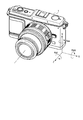
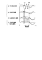
- FIG. 1 is an external view of a casing of a camera as an imaging device according to each embodiment.
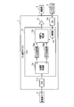
- FIG. 2 is a block diagram showing the overall configuration of a camera according to each embodiment.
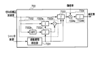
- FIG. 3 is a block diagram showing an internal configuration of the shake correction microcomputer according to the first embodiment.
- FIG. 4 is a diagram showing a schematic configuration of a translational shake correction unit.
- FIG. 5 is a diagram showing a detailed configuration of the translational shake correction unit in the first embodiment.
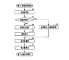
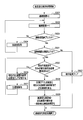
- FIG. 6 is a flowchart showing processing for calculating the image blur correction amount.
- FIG. 7 is a diagram showing the relationship between the shutter control signal and the acceleration.
- FIG. 8 is a flow chart showing a speed change estimation process in the first embodiment.
- FIG. 1 is an external view of a casing of a camera as an imaging device according to each embodiment.
- FIG. 2 is a block diagram showing the overall configuration of a camera according to each embodiment.
- FIG. 3 is a block diagram showing an internal configuration of the
- FIG. 9 is a diagram showing time change of a signal generated inside the translational shake correction unit.
- FIG. 10 is a diagram showing a detailed configuration of a translational shake correction unit in the second embodiment.
- FIG. 11 is a flow chart showing a speed change estimation process in the second embodiment.
- FIG. 12 is a diagram showing the relationship between the acceleration during the vibration period and the velocity as the integration result in the second embodiment.
- FIG. 13 is a diagram showing a detailed configuration of the translational shake correcting unit in the first modification of the second embodiment.
- FIG. 14 is a flowchart showing a speed change estimation process in the first modification.
- FIG. 15 is a diagram showing the relationship between the acceleration during the vibration period and the velocity as the integration result in the first modification.
- FIG. 16 is a flowchart of a speed change estimation process in the third modification.
- FIG. 17 is a flowchart showing an image shake correction process according to the fourth modification.
- FIG. 18 is a flowchart of the speed change estimation process in the fourth modification.
- FIG. 19 is a flowchart of the speed change estimation process in the fifth modification.
- FIG. 20 is a diagram showing a detailed configuration of the translational shake correction unit 733 in the third embodiment.
- FIG. 21 is a block diagram showing an internal configuration of the shake correction microcomputer according to the fourth embodiment.
- FIG. 22 is a block diagram showing details of the translational shake correction unit 733 in the fourth embodiment.
- FIG. 1 is an external view of a casing of a camera as an imaging device provided with a blur amount detection device according to each embodiment of the present invention.
- three orthogonal axes are defined for the camera housing 1.
- the axis of the case 1 which is the left-right direction when the user holds the case 1 of the camera in the horizontal position is taken as an X-axis.
- the right is the + direction
- the left is the ⁇ direction.
- the axis of the case 1 which is the vertical direction when the user holds the camera case 1 in the horizontal position is taken as a Y-axis.
- the upper side is the + direction
- the lower side is the ⁇ direction.
- an axis along the optical axis of the camera shown by a dashed dotted line in FIG. 1 is taken as a Z axis.
- the subject side (the front side of the housing 1) is the + direction
- the image side (the rear side of the housing 1) is the-direction.
- the X-axis and the Y-axis shown in FIG. 1 correspond to the X-axis and the Y-axis of the imaging surface of the imaging device 4 described later.
- the rotation direction around the X axis is taken as a pitch direction
- the rotation direction around the Y axis is taken as a yaw direction
- the rotation direction around the Z axis is taken as a roll direction.
- the direction of each arrow shown in FIG. 1 is taken as the + direction
- the opposite is taken as the ⁇ direction.
- the polarity of the direction described above depends on the mounting direction of the acceleration sensor 8 described later. Depending on the mounting direction of the acceleration sensor 8, the positive or negative direction may be different from that in FIG.
- FIG. 2 is a block diagram showing the overall configuration of a camera according to each embodiment of the present invention.
- An optical system 2 a focal plane shutter 3, an imaging device 4, a drive unit 5, a system controller 6, a motion compensation microcomputer (microcomputer) 7, and an acceleration in a camera 1 according to the present embodiment.
- a sensor 8, a release (switch) SW 9, and an electronic viewfinder (EVF) 10 are provided.
- the memory card 11 is provided inside the housing 1 or can be loaded into the housing 1.
- the optical system 2 has a single or a plurality of lenses and a stop, and forms a light flux from the outside of the housing 1 as an object image on the imaging surface of the imaging device 4.
- the focal plane shutter 3 is provided in front of the imaging surface of the imaging device 4 and performs an opening / closing operation to bring the imaging device 4 into an exposure state or a light shielding state.
- the imaging device 4 converts an object image formed on the imaging surface into an electrical signal based on an instruction from the system controller 6.
- the drive unit 5 has a support member for supporting the imaging device 4, and drives the imaging device 4 in the X-axis direction and the Y-axis direction based on an instruction from the shake correction microcomputer 7.
- the system controller 6 performs various controls related to the functions of the entire camera in addition to the above-described readout of the video signal. For example, the system controller 6 reads a video signal from the imaging device 4 and performs image processing for converting the read video signal into a format suitable for display or recording. Further, the system controller 6 controls the photographing operation when a second release switch of the release switch 9 described later is turned on. The photographing operation is a series of operations from driving the image pickup device 4 to obtain a video signal, processing the video signal into a format suitable for recording, and recording on the memory card 11. Further, at the time of the photographing operation, the system controller 6 also performs control related to the exposure of the imaging element 4 based on the external light beam incident through the optical system 2.
- the system controller 6 controls the opening time of the focal plane shutter 3 and the aperture value of the optical system 2. Furthermore, the system controller 6 monitors the image magnification of the optical system 2. For example, when the optical system 2 includes a zoom lens, the system controller 6 monitors the image magnification by the position of the zoom lens (the position corresponding to the focal length). In addition, the system controller 6 can also monitor whether the position corresponding to the focus (subject distance when focusing) of the lens constituting the optical system 2 has become the macro position (position corresponding to the close-up shooting). Monitor image magnification.
- the system controller 6 also controls image blur correction by communicating with the blur correction microcomputer 7.
- the shake correction microcomputer 7 controls the image shake correction operation according to the control of the system controller 6.
- the shake correction microcomputer 7 calculates an image shake correction amount from the output of the acceleration sensor 8, and inputs the calculated image shake correction amount to the drive unit 5.
- the drive unit 5 drives the imaging device 4 according to the image blur correction amount, it is possible to prevent an image blur which is a blur on the imaging surface of the imaging device 4.
- Such blur correction microcomputer 7 will be described in detail later.
- the acceleration sensor 8 detects the acceleration along the X axis and the Y axis shown in FIG.
- the signal of the acceleration detected by the acceleration sensor 8 is input to the shake correction microcomputer 7.
- the release switch (SW) 9 is a switch that operates in response to the release button provided on the housing 1.
- the release switch 9 has a first release switch that turns on in response to a half press of the release button, and a second release switch that turns on in response to a full press of the release button.
- the electronic view finder (EVF) 10 is, for example, a liquid crystal panel, and displays a video based on the video signal converted into a format displayable by the system controller 6 so that the user can visually recognize it.
- the memory card 11 is, for example, a flash memory, and records a video signal converted into a recordable format by the system controller 6.
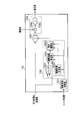
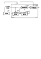
- FIG. 3 is a block diagram showing an internal configuration of the shake correction microcomputer 7 according to the first embodiment of the present invention.
- the shake correction microcomputer 7 has SIOs 71 a and 71 b, a driver 72, and a CPU 73.
- the shake correction microcomputer 7 shown in FIG. 3 only shows a configuration for correcting translational shake. This is to simplify the explanation. Of course, a configuration for correcting the angular deviation may be further provided.
- SIO 71 a and SIO 71 b are communication units for the CPU 73 to perform serial communication with other devices.
- the SIO 71 a is used for communication with the acceleration sensor 8.
- the SIO 71 b is also used for communication with the system controller 6.
- the driver 72 generates a signal for driving the drive unit 5 based on the image blur correction amount calculated by the CPU 73, and inputs the generated signal to the drive unit 5.
- the CPU 73 calculates an image shake correction amount for correcting translational shake of the housing 1 from the detection result of the acceleration sensor 8, and inputs the calculated image shake correction amount to the driver 72.
- the CPU 73 includes an acceleration acquisition unit 731, zero point correction units 732 a and 732 b, a translational shake correction unit 733, and a communication unit 734.
- the acceleration acquisition unit 731 reads the values of the accelerations of the two axes from the acceleration sensor 8 via the SIO 71a. Then, the acceleration acquiring unit 731 divides the read acceleration value into X and Y axis values and inputs the values to the translational shake correcting unit 733.
- the zero point correction units 732a and 732b subtract the acceleration signal level (zero point) acquired when the acceleration of the housing 1 becomes zero from the acceleration signal acquired by the acceleration acquisition unit 731 to obtain an acceleration acquisition unit.
- the offset component of the acceleration signal acquired at 731 is removed, and the acceleration zero point is adjusted to a predetermined reference value.
- the zero point correction unit 732a corrects the zero point of the X-axis acceleration.
- the zero point correction unit 732 b corrects the zero point of the Y-axis acceleration.
- the translational shake correction unit 733 calculates an image shake correction amount for correcting translational shake of the housing 1 based on the X-axis and Y-axis accelerations input from the zero point correction units 732 a and 732 b.
- the detailed configuration of the translational shake correction unit 733 will be described later.
- the communication unit 734 communicates with the system controller 6 via the SIO 71 b.
- FIG. 4 is a diagram showing a schematic configuration of the translational shake correction unit 733.
- FIG. 5 is a diagram showing a detailed configuration of the translational shake correction unit 733 in the first embodiment.
- the translational shake correction unit 733 in FIGS. 4 and 5 shows a configuration of one axis.
- the translational shake correcting unit 733 shown in FIGS. 4 and 5 is present on each of two axes of the X axis and the Y axis.
- the translational shake correction unit 733 includes a vibration period detection unit 7331, a speed change estimation unit 7332, a speed calculation unit 7333, and a shake amount calculation unit 7334.
- the vibration period detection unit 7331 detects the vibration period by communication with the system controller 6 via the communication unit 734.
- the vibration period is a period during which vibration equal to or greater than a predetermined threshold is applied.
- the predetermined threshold is a vibration that is larger than the vibration caused by the camera shake, and is a vibration caused by an operation of a movable portion such as the focal plane shutter 3, for example.
- the vibration period detection unit 7331 detects a vibration period according to, for example, a shutter control signal input from the system controller 6. Besides this, the vibration period may be measured experimentally.
- the velocity change estimation unit 7332 estimates the velocity change of the housing 1 during the vibration period based on the values of the zero point correction acceleration input from the zero point correction units 732a and 732b.
- the speed change estimation unit 7332 includes an integration unit 7332 a, a high pass filter (HPF) 7332 b, an integration unit 7332 c, and a subtraction unit 7332 d.
- HPF high pass filter
- the integrating unit 7332a integrates the zero point correction acceleration in the vibration period to calculate the velocity.
- the integration unit 7332a integrates only in the vibration period, and continues to output 0 in the other periods.
- the velocity calculated by the integration unit 7332a includes the velocity due to the vibration (camera shake) of the housing 1 itself and the velocity based on the vibration due to the operation of the movable portion such as the focal plane shutter 3 or the like.
- the HPF 733 b removes predetermined low frequency components in the zero point corrected acceleration during the vibration period.
- the cut-off frequency of the HPF 733 b is, for example, 20 Hz.
- the frequency of vibration due to camera shake is approximately 1 Hz to 10 Hz, and it is experimentally known that the frequency of vibration accompanying the operation of a movable portion such as the focal plane shutter 3 is approximately 50 Hz. Therefore, it is possible to extract only the acceleration component due to the operation of the movable part by removing the frequency component of 20 Hz or less, which is a frequency sufficiently higher than the frequency of vibration due to camera shake.
- the frequency component to be removed by the HPF 733 b may be a frequency that is higher than the upper limit frequency of vibration due to camera shake and lower than the lower limit frequency of vibration associated with the operation of the movable portion.
- the cutoff frequency is set to 20 Hz, but in practice it is preferable to consider the influence of the phase.
- the integrating unit 7332 c integrates the acceleration due to only the movement of the movable unit input from the HPF 7332 b to calculate the velocity.
- the integration unit 7332 c integrates only during the vibration period, and continues to output 0 during the other periods.
- the velocity calculated by the integrating unit 7332 c corresponds to the velocity offset erroneously calculated by the integrating unit 7332 a due to the vibration due to the movement of the movable portion.
- the subtracting unit 7332 d subtracts the velocity offset calculated by the integrating unit 7332 c from the velocity calculated by the integrating unit 7332 a to calculate a change in velocity caused only by the vibration (camera shake) of the housing 1.
- the velocity calculation unit 7333 includes an integration unit that calculates the velocity based on the accelerations input from the zero point correction units 732a and 732b. Furthermore, immediately after the vibration period, the velocity calculation unit 7333 performs correction to add the velocity change estimated by the velocity change estimation unit 7332 to the calculated velocity.
- the blur amount calculation unit 7334 calculates an image blur correction amount based on the speed obtained by the speed calculation unit 7333.
- the blur amount calculation unit 7334 has a multiplication unit 7334 a and an integration unit 7334 b.
- the multiplication unit 7334 a multiplies the speed calculated by the speed calculation unit 7333 by an image magnification obtained by communication with the system controller 6 via the communication unit 734 to obtain an image on the imaging surface of the imaging device 4. Calculate the translational velocity of
- the integrating unit 7334 b integrates the translational velocity of the image input from the multiplying unit 7334 a to calculate the translational movement amount of the image on the imaging surface of the imaging device 4 as the image blur correction amount.
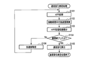
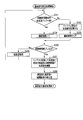
- FIG. 6 is a flowchart showing processing for calculating the image blur correction amount.
- the translational shake correction unit 733 obtains the value of acceleration via the zero point correction units 732a and 732b (step S1).
- the translational shake correction unit 733 determines whether or not the current vibration period is the vibration period by the vibration period detection unit 7331 (step S2).
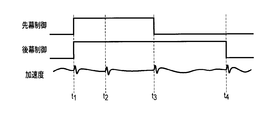
- FIG. 7 is a diagram showing the relationship between the shutter control signal and the acceleration.
- the shutter control signal in the case of the focal plane shutter is divided into a front curtain control signal and a rear curtain control signal.
- the front curtain control signal and the rear curtain control signal are control signals for controlling a magnet for attracting the front curtain and the rear curtain of the focal plane shutter.
- the control signal is High, a magnetic force is generated in the magnet.
- Timing t1 in FIG. 7 is timing at which the front and rear curtains of the focal plane shutter 3 are attracted. Acceleration is generated by the vibration at the timing t1.
- the timing t2 is a timing at which a lever for attracting the front and rear curtains of the focal plane shutter 3 is retracted. Acceleration is also generated by the vibration that occurs at this timing t2.
- These timings t1 and t2 are detected as vibration periods.
- the time interval from the timing t1 to the timing t2 is a fixed time interval. Therefore, timing t2 can be detected from timing t1 if the time interval between timing t1 and timing t2 which is the timing of rising of the leading and trailing curtain control signals is determined, for example, at the time of design of the camera.
- Timing t3 in FIG. 7 is the timing when the focal plane shutter 3 travels on the front curtain. Acceleration is also generated by the vibration generated when the front curtain travels at this timing t3. This timing t3 is also detected as a vibration period. In general, the timing t3 varies with the aperture setting. However, as can be seen from FIG. 7, timing t3 can be detected as the timing at which the leading curtain control signal changes to low.
- the timing t4 is a timing when the rear curtain of the focal plane shutter 3 travels. Acceleration is also generated by the vibration that occurs when the front curtain travels at this timing t4.
- the timing t4 is the timing of the end of the exposure period, and the vibration generated at this timing does not affect the photographed image. Therefore, it can be disregarded as a vibration period in this embodiment.
- the vibration due to the focal plane shutter 3 occurs due to its operation. Therefore, the vibration period can be determined from the levels of the front curtain control signal and the rear curtain control signal as shutter control signals. By detecting the vibration period using the shutter control signal, the vibration generated due to the operation of the focal plane shutter 3 can be detected regardless of the camera setting.
- step S2 If it is determined in step S2 that the period is not a vibration period, translational shake correction unit 733 calculates the velocity by integrating the acceleration by velocity calculation unit 7333 (step S3). On the other hand, when it is determined in S2 that the vibration period is determined, the translational shake correction unit 733 causes the velocity change estimation unit 7332 to estimate the velocity change during the vibration period (step S4).
- FIG. 8 is a flow chart showing a speed change estimation process in the first embodiment.
- the speed change estimation unit 7332 performs HPF (High Pass Filtering) processing on the signal of the zero point correction acceleration by the HPF 733 b (step S101).
- HPF High Pass Filtering
- the component related to camera shake in the signal of acceleration is removed, and only the component related to the movable part (focal plane shutter 3) is extracted.
- the speed change estimation unit 7332 integrates the zero point correction acceleration by the integration unit 7332a (step S102). Further, the speed change estimation unit 7332 integrates the acceleration subjected to the HPF processing by the integration unit 7332 c (step S103).
- the speed change estimation unit 7332 determines whether the vibration period has ended from the detection result of the vibration period detection unit 7331 (step S104).
- the speed change estimation unit 7332 acquires an acceleration (step S106). Thereafter, the speed change estimation unit 7332 repeats the processing of steps S101 to S104.
- the velocity change estimation unit 7332 subtracts the integral value of S103 from the integral value of S102 by the subtraction unit 7332d, and integrates the input from the subtraction unit 7332d by the velocity calculation unit 7333, The speed change based on the camera shake during the vibration period is calculated (step S105).
- the translational shake correction unit 733 calculates and corrects the speed by the speed calculation unit 7333 (step S5).
- the translational shake correction unit 733 multiplies the value of the velocity input from the velocity calculation unit 7333 by the image magnification by the multiplication unit 7334a of the shake amount calculation unit 7334 (step S6). Thereby, the translational velocity of the housing 1 is converted into the translational velocity of the image on the imaging plane. Then, the translational shake correction unit 733 integrates the value of the velocity input from the multiplication unit 7334 a to calculate the image shake correction amount (step S 7).
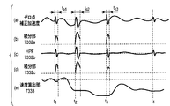
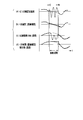
- FIG. 9 is a view showing time change of a signal generated inside the translational shake correction unit 733. As shown in FIG. As shown in (a) of FIG. 9, noise generated from the vibration of the movable portion is superimposed on the signal of the zero point correction acceleration, which is an input of the translational shake correction unit 733, from timing t1 to t4 which is a vibration period. Ru.
- the integration unit 7332a integrates the signal of the zero point correction acceleration input at each of the timings t1 to t3 which is a vibration period. Therefore, as shown in (b) of FIG. 9, the integration result at this time is obtained by integrating the acceleration component due to the vibration (camera shake) of the housing 1 and the integration of the acceleration component due to the vibration of the focal plane shutter 3 And both included.
- the HPF 733 b removes low frequency components of the input zero point corrected acceleration. Therefore, the output of the HPF 733 b is a signal of an acceleration component due to the vibration of the focal plane shutter 3 during the vibration period, as shown in (c) of FIG.
- the integration unit 7332 c integrates the input from the HPF 7332 b. Therefore, as shown in (d) of FIG. 9, the output of the integration unit 7332 c is the integration result of the acceleration component due to the vibration of the focal plane shutter 3 during the vibration period.
- the speed calculation unit 7333 integrates the input signal of the zero point correction acceleration except during the vibration period. On the other hand, at the end of the vibration period, the velocity calculation unit 7333 performs velocity correction in which the integration result of the acceleration component due to the vibration of the focal plane shutter 3 is subtracted from the integration result of the signal of the zero point correction acceleration. Therefore, the output of the speed calculation unit 7333 is as shown in (e) of FIG.
- the noise component generated from the vibration caused by the movement of the movable part by subtracting the noise component generated from the vibration caused by the movement of the movable part from the velocity obtained during the vibration period, the noise is generated in the acceleration generated from the vibration caused by the movement of the movable part. Even when it occurs, the effect is removed to calculate an accurate translational velocity, thereby calculating an accurate image blur correction amount.
- the integration unit 7332a and the velocity calculation unit 7333 are separated, and the operation of the velocity calculation unit 7333 is switched depending on whether or not it is a vibration period.
- the integration unit 7332a and the speed calculation unit 7333 may be integrated. In this case, at the end of the vibration period, the integration result of the integration unit 7332c is corrected to be subtracted from the integration result of the speed calculation unit 7333.
- FIG. 10 is a diagram showing a detailed configuration of the translational shake correction unit 733 in the second embodiment.
- the same components as in FIG. 5 are designated by the same reference numerals as in FIG.
- the second embodiment is different from the first embodiment in the configuration of the speed change estimation unit 7332. Therefore, the configuration and operation of the speed change estimation unit 7332 will be mainly described below.
- the speed change estimation unit 7332 in the second embodiment includes a buffer 73321, a duration measurement unit 73322, an interpolation straight line calculation unit 73323, and an integration calculation unit 73324.
- the buffer 73321 stores the acceleration at the time when the start of the vibration period is detected by the vibration period detection unit 7331.
- the duration measuring unit 73322 measures the duration from when the start of the vibration period is detected by the vibration period detecting unit 7331 to when the vibration period ends.
- the continuous period measurement unit 73322 is, for example, a counter that counts up by one each time the acquisition timing of acceleration passes from the time when the start of the vibration period is detected.
- the interpolation straight line calculation unit 73323 as an example of the interpolation unit stores the acceleration at the start of the vibration period and the time after the vibration period end stored in the buffer 73321 The interpolation point on the interpolation straight line indicating the acceleration during the vibration period is calculated using
- the integral calculation unit 73324 integrates the interpolation straight line calculated by the interpolation straight line calculation unit 73323 with the continuation period measured by the continuation period measurement unit 73322 to estimate the velocity change during the vibration period.
- FIG. 11 is a flow chart showing a speed change estimation process in the second embodiment.
- the speed change estimation unit 7332 determines whether or not the acceleration is stored in the buffer 73321 (step S201).
- the speed change estimation unit 7332 stores the input zero point correction acceleration in the buffer 73321 (step S202). Subsequently, the speed change estimation unit 7332 clears the value of the continuation period measured by the continuation period measurement unit 73322 to 0, and starts measurement of the continuation period (step S203).
- the velocity change estimation unit 7332 causes the duration measurement unit 73322 to count up the value of the duration (step S204).
- the speed change estimation unit 7332 determines again from the detection result of the vibration period detection unit 7331 whether or not the current time is a vibration period (step S205). If it is a vibration period, the speed change estimation unit 7332 acquires an acceleration (step S206). Thereafter, the speed change estimation unit 7332 repeats the processing of steps S201 to S205.
- the velocity change estimation unit 7332 causes the interpolation straight line calculation unit 73323 to use the acceleration stored in step S202, the duration period measured in step S204, and the current acceleration.
- the interpolation straight line which shows the acceleration change inside is calculated.
- the interpolation straight line is given by (Expression 1) (step S207).
- Acc_i [n] in (Expression 1) is a value of acceleration at the n-th interpolation position.
- Acc_b0 is the value of the acceleration stored in the buffer 73321.
- Acc_a0 is a value of (current) acceleration after the end of the vibration period.
- N is a duration in which the start point of the vibration period is 1. N is counted up each time the process of S204 is performed. n is the number of samples where the start point of the vibration period is 0.
- the speed change estimation unit 7332 integrates the interpolation straight line calculated by the interpolation straight line calculation unit 73323 by the integration calculation unit 73324 for the duration period measured in S204 to calculate an estimated value of the speed change (step S208). .
- This integral calculation is shown by (Equation 2).
- FIG. 12 is a diagram showing the relationship between the acceleration during the vibration period and the velocity as the integration result in the second embodiment.
- the acceleration during the vibration period includes not only the acceleration component due to the camera shake but also the acceleration component resulting from the vibration due to the operation of the movable part such as the focal plane shutter 3 or the like. Therefore, the acceleration during the vibration period is largely distorted in waveform as shown in (a) of FIG.
- the acceleration shown by the broken line in (a) of FIG. 12 indicates a state of only acceleration due to the vibration of the housing 1 when assuming that there is no acceleration component generated from the vibration due to the movement of the movable portion.
- the interpolation straight line calculation unit 73323 performs linear expression (straight line) interpolation of the acceleration during the vibration period using the accelerations at the sampling points before and after the vibration period.
- the black double circles in (b) of FIG. 12 indicate the acceleration used for the interpolation, and the black squares in FIG. 12 indicate the acceleration generated by the interpolation.
- the acceleration obtained by the linear interpolation is substantially equivalent to the state of only acceleration due to the vibration of the housing 1.
- (C) of FIG. 12 shows the velocity obtained by integrating the non-interpolated acceleration in the interpolation straight line calculation unit 73323. Since the velocity obtained in this case includes the one resulting from the vibration due to the operation of the movable portion, the waveform is greatly distorted.
- (D) of FIG. 12 shows the velocity obtained by integrating the acceleration after the interpolation in the interpolation straight line calculation unit 73323, that is, the output of the integration operation unit 73324.
- the velocity obtained after the end of the vibration period coincides with the velocity shown by the broken line in (c) of FIG.
- FIG. 13 is a diagram showing a detailed configuration of the translational shake correcting unit 733 in the first modification of the second embodiment.
- the same components as in FIG. 10 are designated by the same reference numerals as in FIG.
- the first modification differs in that the interpolation straight line calculation unit 73323 is replaced by an approximate curve calculation unit 73325.
- the buffer 73321 in the second embodiment stores only the acceleration at the start time of the vibration period
- the buffer 73321 of the first modification is different in storing the acceleration at a plurality of points in time.
- the buffer 73321 of the modification 1 stores the acceleration of one sample or plural samples at the start time of the vibration period as the front side acceleration. Furthermore, the buffer 73321 stores the acceleration of 0 samples or more after the end of the vibration period as the rear acceleration. In this case, the buffer 73321 stores 0 or more samples as the rear side acceleration because if the number of samples necessary as the rear side acceleration is 1 sample, the number of the rear side acceleration is sufficient if the current acceleration is obtained It is because it becomes a thing.
- the approximate curve calculation unit 73325 as another example of the interpolation unit uses the front acceleration and the rear acceleration stored in the buffer 73321 and the current acceleration when the acceleration of the required number of samples is stored in the buffer 73321. Then, an approximate curve indicating the acceleration of only the vibration component of the housing 1 during the vibration period is calculated.
- FIG. 14 is a flowchart showing a speed change estimation process in the first modification.
- the speed change estimation unit 7332 determines whether the front acceleration is stored in the buffer 73321 (step S301).
- the speed change estimation unit 7332 stores the input current zero point correction acceleration as the front side acceleration in the buffer 73321 (step S302). Subsequently, the speed change estimation unit 7332 clears the value of the continuation period measured by the continuation period measurement unit 73322 to 0 and starts measurement of the continuation period (step S303).
- the velocity change estimation unit 7332 causes the duration measurement unit 73322 to count up the value of the duration (step S304).
- the speed change estimation unit 7332 determines again from the detection result of the vibration period detection unit 7331 whether or not the current time is the vibration period (step S305). If it is a vibration period, the speed change estimation unit 7332 acquires an acceleration (step S306). Thereafter, the speed change estimation unit 7332 repeats the processing of steps S301 to S305.
- the speed change estimation unit 7332 confirms whether or not the acceleration of the number of samples necessary for calculation of the approximate curve is obtained (step S309). For example, in the case where the number of samples required as the rear side acceleration is one, if the current acceleration is acquired, the score of the rear side acceleration is sufficient. On the other hand, when the number of samples required as the rear acceleration is 2 or more and the rear acceleration excluding the current acceleration is not stored, the input current zero point correction acceleration is used as the rear acceleration in the buffer 73321. It memorizes (Step S310). Then, the speed change estimation unit 7332 obtains the acceleration again (step S311). Thereafter, the speed change estimation unit 7332 repeats steps S309 to S311 until the required number of backward samples can be acquired.
- the speed change estimation unit 7332 causes the approximate curve calculation unit 73325 to store the front side acceleration stored in step S302 and the duration period measured in step S304. And the rear side acceleration (including the current acceleration) stored in step S310 are used to calculate an approximate curve indicating the change in acceleration during the vibration period (step S312).
- Acc_i [n] in (Expression 4) is a value of acceleration at the n-th interpolation position.
- Acc_b1 is the value of the front side acceleration stored in the buffer 73321.
- Acc_b0 is the value of the rear side acceleration stored in the buffer 73321.
- Acc_a0 is the value of the current acceleration after the end of the vibration period.
- N is a continuation period where the start point of the vibration period is 0. N is counted up each time the process of S304 is performed.
- n is the number of samples where the start point of the vibration period is 0.
- the speed change estimation unit 7332 integrates the approximate curve calculated by the approximate curve calculation unit 73325 by the integration calculation unit 73324 for the duration period measured in S304 to calculate an estimated value of the speed change (step S313) .
- This integral calculation is shown by (Equation 5).
- the number of accelerations stored in the buffer 73321 is determined by the order of the approximate curve calculated by the approximate curve calculation unit 73325.
- the case where the order is 1 is similar to that of the second embodiment.
- the relationship between the sample number x of the front side acceleration required for calculation of the approximate curve and the sample number y of the rear side acceleration is, for example, as follows.
- One sample of the back acceleration is the current acceleration value.
- the number of back acceleration samples that need to be stored in buffer 73321 is y-1.
- the method of taking acceleration samples can be selected in various ways in accordance with the order of the polynomial that is the approximate curve.
- the order is an odd number, it is preferable to set the number of front acceleration samples greater than the number of rear acceleration samples. As a result, it is possible to accelerate the timing of returning to the normal speed calculation processing after the vibration period, and it is possible to further improve the speed calculation accuracy. Furthermore, it also reduces the release time lag.
- FIG. 15 is a diagram showing the relationship between the acceleration during the vibration period and the velocity as the integration result in the first modification.
- FIG. 15 is an example in which second-order polynomial interpolation is performed with the front acceleration as two samples and the rear acceleration as one sample.
- FIG. 15 uses polynomial interpolation, it is possible to obtain an approximate curve of acceleration that is more accurate than the linear interpolation of FIG. 12.
- Modification 2 of the Second Embodiment The modification 1 of the second embodiment calculates the approximate curve using polynomial interpolation. However, it is not necessary to use polynomial interpolation to calculate the approximate curve. Modification 2 is an example of calculating an approximate curve by the method of least squares.
- the acceleration detected by the acceleration sensor usually includes noise. Therefore, when the performance of the acceleration sensor is low and there are many noises included in the acceleration, sufficient accuracy may not be secured in the interpolation calculation for obtaining a curve which always passes the sampled acceleration point. In such a system, it is desirable to calculate the approximate curve by another method such as the least squares method.
- the order of the approximate curve and the number of samples to be used for calculation can be appropriately changed as in the interpolation calculation.
- the order of the approximate curve is L
- accelerations of L + 2 samples or more are used before and after the vibration period.
- Acc_i [n] in (Expression 7) is the value of the acceleration at the n-th interpolation position.
- Acc_b1 is the value of the front side acceleration immediately after the vibration period stored in the buffer 73321.
- Acc_b0 is a value of front side acceleration stored in the buffer 73321 one sample after immediately after the vibration period.
- Acc_a0 is the value of the rear acceleration stored in the buffer 73321 one sample after the end of the vibration period.
- Acc_a0 is the value of the rear acceleration (current acceleration) stored in the buffer 73321 two samples after the end of the vibration period.
- N is a continuation period where the start point of the vibration period is 0.
- N is counted up each time the process of S304 is performed.
- n is the number of samples where the start point of the vibration period is 0.
- the matrix M + is a pseudoinverse of the matrix M.
- FIG. 16 is a flowchart of a speed change estimation process in the third modification.
- FIG. 16 is the flowchart of FIG. 14 with the process of determining the approximate curve calculation method of step S400 added.
- the calculation method of the approximate curve can be determined using, for example, the shutter speed and the image magnification.
- the information on the shutter speed and the image magnification is information notified from the system controller 6 as a control unit.
- the first approximation is performed when the shutter speed is higher than 1/100 second
- the high order approximation is performed when the shutter speed is lower than 1/100 second.
- the image magnification is smaller than 1/10
- linear approximation is performed when the image magnification is smaller than 1/10
- high-order approximation is performed when the image magnification is 1/10 or more.
- the high-order approximate curve is an approximate curve calculated using two or more accelerations of either or both of the front side acceleration and the rear side acceleration.
- the shutter speed and the image magnification which serve as determination criteria for determining the approximate curve calculation method, also differ depending on the shapes of the optical system 2 and the housing 1 or the like. Thus, the decision criteria may be determined experimentally. Further, as the determination standard, both the shutter speed and the image magnification may be used, or only one may be used.
- interpolation can be performed at an appropriate calculation cost by performing the interpolation operation in accordance with the required accuracy of interpolation.
- the front side acceleration used to calculate the approximate curve is used at the vibration detection time (in fact, immediately after the vibration detection). However, in this case, detection may be delayed depending on the type of vibration. At this time, calculation of acceleration and velocity is performed using the information in the vibration period. As a countermeasure therefor, the acceleration before the vibration is detected may be stored in the buffer for a plurality of points, and the sample stored after the detection of the vibration may be used as the front acceleration to obtain an approximate curve.
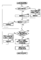
- FIG. 17 is a flowchart showing an image shake correction process according to the fourth modification.
- FIG. 18 is a flowchart of the speed change estimation process in the fourth modification.
- step S2 If it is determined in step S2 that the period is not a vibration period, translational shake correction unit 733 calculates the velocity by integrating the acceleration using velocity calculation unit 7333 (step S3). Subsequently, the translational shake correction unit 733 causes the buffer 73321 to store the accelerations of the plurality of samples for delay countermeasure (step S8).
- the number of acceleration samples stored in the buffer 73321 in step S8 is equal to or larger than the sum of the assumed number of vibration detection delay samples Z and the number of front acceleration samples x used for calculation of the approximate curve.
- the other processes are the same as those in FIG.
- the speed change estimation unit 7332 clears the value of the duration measured by the duration measurement unit 73322 to 0 (step S501). Next, the speed change estimation unit 7332 causes the duration measurement unit 73322 to count up the value of the duration (step S502).
- the speed change estimation unit 7332 determines whether the vibration period has ended from the detection result of the vibration period detection unit 7331 (step S503). If the vibration period has not ended, the speed change estimation unit 7332 acquires an acceleration (step S504). Thereafter, the speed change estimation unit 7332 repeats the processing of steps S502 to S503.
- the speed change estimation unit 7332 confirms whether or not the acceleration of the number of samples necessary for calculation of the approximate curve is obtained (step S505). For example, in the case where the number of samples required as the rear side acceleration is one, if the current acceleration is acquired, the score of the rear side acceleration is sufficient. On the other hand, when the number of samples required as the rear acceleration is two samples or more and the rear acceleration excluding the current acceleration is not stored, the input current zero point correction acceleration is used as the rear acceleration. It is stored in the buffer 73321 (step S506). Then, the speed change estimation unit 7332 acquires the acceleration again (step S507). Thereafter, the speed change estimation unit 7332 repeats steps S505 to S507 until the required number of backward samples can be acquired.
- the speed change estimation unit 7332 causes the approximate curve calculation unit 73325 to store the front side acceleration stored in step S8 and the duration period measured in step S502. And the rear side acceleration (including the current acceleration) stored in step S506 are used to calculate an approximate curve indicating the change in acceleration during the vibration period (step S508).
- Acc_i [n] (n + Z) / (N + 1 + Z) ⁇ (Acc_a0 ⁇ Acc_b0 [Z]) + Acc_b [Z] (Equation 9)
- Acc_i [n] in (Expression 9) is the value of the acceleration at the n-th interpolation position.
- Acc_b [Z] is the value of the front side acceleration stored in the buffer 73321 before detection of vibration.
- Acc_a0 is the value of the current acceleration after the end of the vibration period.
- N is a duration in which the start point of the vibration period is 1. N is counted up each time the process of step S502 is performed.
- n is the number of samples where the start point of the vibration period is 1.
- the speed change estimation unit 7332 integrates the approximate curve calculated by the approximate curve calculation unit 73325 by the integration calculation unit 73324 for the duration period measured in step S304 to calculate an estimated value of the speed change (step S509).
- This integral calculation is shown by (Equation 10).
- FIG. 19 is a flowchart of the speed change estimation process in the fifth modification.
- the vibration period (duration period) is equal to or less than a threshold (an experimental value, for example, 100 ms) based on the measurement result of the duration measurement unit. It determines (step S601). If the duration is equal to or less than the threshold, the speed change estimation unit 7332 performs the same processing as FIG. 18 thereafter. On the other hand, when the continuation period exceeds the threshold, the speed change estimation unit 7332 clears the integration result in the speed calculation unit 7333 (step S602). This clears the velocity change estimated value to zero.
- a threshold an experimental value, for example, 100 ms
- FIG. 20 is a diagram showing a detailed configuration of the translational shake correction unit 733 in the third embodiment.
- the same components as in FIG. 5 are designated by the same reference numerals as in FIG.
- the third embodiment is different in that a zero point correction acceleration detected via an acceleration sensor is also input to a vibration period detection unit 7331.
- the vibration period is detected using the control signal of the movable part such as the focal plane shutter 3 or the like.
- the detection method of the vibration period is not limited to this.
- the change in acceleration may be monitored by the vibration period detection unit 7331, and it may be determined that the vibration period is detected when a change in acceleration that is sufficiently larger than expected with normal camera shake is detected.
- the vibration period may be determined when the difference between the average of the acceleration of M samples and the current acceleration is equal to or more than a predetermined value.
- the vibration period may be detected by combining a plurality of methods.
- the operation of the movable portion such as the operation of the focal plane shutter 3, the charge operation of the flash device, the operation of the quick return mirror, and the operation of the diaphragm. It is also possible to detect, for example, vibrations caused by the handling of the user other than vibrations due to.
- the vibration generated by the user's handling includes the vibration generated in the case 1 by the user's operation such as the vibration generated when the user presses the release switch or the button or the vibration generated when the command dial is rotated, the camera strap
- the acceleration is integrated twice to calculate the image blur correction amount.
- the acceleration detected by the acceleration sensor 8 is zero-point corrected, but the gravity of the gravity between the reference value of the actual acceleration sensor 8 and the zero point corrected by the zero-point correction units 732 a and 732 b If there is an error other than the influence, the two integrations increase the error. If integration is continued for a long time in such a state, the difference between the image blur correction amount to be actually obtained and the calculated image blur correction amount will be large. Therefore, it is desirable not to integrate the calculated velocity as it is, but to calculate the velocity from the angular velocity detected by the angular velocity sensor.
- FIG. 21 is a block diagram showing an internal configuration of the shake correction microcomputer 7 in the fourth embodiment.
- the shake correction microcomputer 7 according to the fourth embodiment has ADCs (analog / digital converters) 74a and 74b in addition to the SIOs 71a and 71b, the driver 72, and the CPU 73.
- the CPU 73 further includes zero point correction units 735a and 735b.
- the ADCs 74a and 74b are connected to the angular velocity sensors 12a and 12b.
- the angular velocity sensors 12 a and 12 b detect the angular velocity around the axis set in the housing 1.
- the angular velocity sensor 12a detects an angular velocity in the pitch direction.
- the angular velocity sensor 12 b detects an angular velocity in the yaw direction.
- the ADC 74a converts the output signal of the angular velocity sensor 12a into a digital signal.
- the ADC 74 b converts the output signal of the angular velocity sensor 12 b into a digital signal.
- the zero point correction units 735a and 735b remove the offset component by subtracting the signal level (zero point) acquired when the angular velocity of the housing 1 becomes zero from the angular velocity signal acquired by the angular velocity sensor. , The angular velocity zero point is adjusted to a predetermined reference value.
- the zero point correction unit 735a corrects the zero point of the pitch direction angular velocity.
- the zero point correction unit 735b corrects the zero point of the yaw direction acceleration.
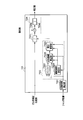
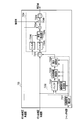
- FIG. 22 is a block diagram showing details of the translational shake correction unit 733 in the fourth embodiment.
- FIG. 22 is a block diagram of only one axis.
- a translational shake correction unit 733 having a configuration shown in FIG. 22 is present on each of two axes of the X axis and the Y axis.
- the example of FIG. 22 is an example in which the angular velocity of one axis is made to correspond to the acceleration of one axis.
- a method of making the angular velocity of two axes correspond to the acceleration of one axis is also proposed and known. This method can also be used in the present embodiment.
- FIG. 22 the same components as in FIG. 10 are designated by the same reference numerals as in FIG.
- the configuration of translational shake correction unit 733 shown in FIG. 22 is different from the configuration of translational shake correction unit 733 shown in FIG. 10 in the configuration of shake amount calculation unit 7334.
- differences from FIG. 10 will be mainly described.
- the blur amount calculation unit 7334 in the fourth embodiment includes filters 7334 c and 7334 d, a radius calculation unit 7334 e, and a multiplication unit 7334 f in addition to the multiplication unit 7334 a and the integration unit 7334 b.
- filters 7334 c and 7334 d the blur amount calculation unit 7334 in the fourth embodiment includes filters 7334 c and 7334 d, a radius calculation unit 7334 e, and a multiplication unit 7334 f in addition to the multiplication unit 7334 a and the integration unit 7334 b.
- the filter 7334 c is a filter that adjusts the frequency characteristic and the phase characteristic of the signal of the velocity obtained by the velocity calculation unit 7333.
- filter 7334c is an HPF that removes low frequency components in the velocity signal.
- the frequency of camera shake is generally about 1 Hz to 10 Hz. Therefore, by removing the frequency of 1 Hz or less by the filter 7334c, the influence of temperature drift or the like on the signal of the acceleration detected by the acceleration sensor is removed.
- the filter 7334 d is a filter that adjusts the frequency characteristic and the phase characteristic of the zero point correction angular velocity input from the ADC.
- the filter 7334 d has a role of matching the frequency characteristic and the phase characteristic of the signal of the velocity obtained by the velocity calculation unit 7333 and the signal of the angular velocity detected through the angular velocity sensor.
- the filter 7334d adjusts the frequency characteristic and the phase characteristic of the angular velocity signal so that the frequency characteristic and the phase characteristic of the velocity signal have the same characteristic. Do.
- the radius calculation unit 7334 e divides the output of the filter 7334 c by the output of the filter 7334 d to calculate the rotation radius. Because of division, when the absolute value of the output of the filter 7334 d is close to 0, the calculated value of the radius diverges to infinity. In this case, the radius can not be calculated with sufficient accuracy. Therefore, when the output of the filter 7334 d is equal to or less than a predetermined value, the radius calculating unit 7334 e fixes the output without performing a new division. In addition, when the vibration period is detected by the vibration period detection unit 7331, there is a possibility that the velocity obtained by the speed calculation unit 7333 includes a component due to the vibration of the movable portion or the like. Therefore, even when the vibration period is detected by the vibration period detection unit 7331, the radius calculation unit 7334e does not update the output.
- the multiplying unit 7334 f calculates a translational velocity by multiplying the radius calculation value input from the radius calculating unit 7334 e by the angular velocity input from the ADC.
- the radius of rotation is determined from the ratio of the angular velocity to the translational velocity, and the final translational velocity is calculated from the determined radius of rotation.
- Several methods for calculating the translational velocity of the housing using an angular velocity sensor have been proposed. Other than the method described in the present embodiment, any calculation method that uses the integrated value of acceleration in the calculation process can be applied.
- the second embodiment uses an acceleration sensor to calculate the translational velocity
- the fourth embodiment uses an acceleration sensor and an angular velocity sensor to calculate the translational velocity.
- the fifth embodiment is an example in which the moving velocity of an image obtained by calculating a motion vector is used for calculating the translational velocity.
- the system controller 6 when the camera is in through image display, information obtained by the imaging device 4 is processed by the system controller 6 and used for display.
- the system controller 6 in the present embodiment also calculates a motion vector using information obtained by the imaging device during live view display. It is possible to use the calculated motion vector as the image blur correction amount.
- the image sensor 4 is shielded by the focal plane shutter 3. This makes it impossible to calculate motion vectors.
- the translational velocity is calculated using the input from the acceleration sensor or the angular velocity sensor described in each of the above-described embodiments and their modifications.
Abstract
ブレ量検出装置は、加速度センサ(8)と、振動期間検出部(7331)と、速度変化推定部(7332)と、速度算出部(7333)と、ブレ量算出部(7334)とを有する。加速度センサ(8)は、筐体に加わる加速度を検出する。振動期間検出部(7331)は、筐体に対し、所定の閾値以上の振動が加わる振動期間を検出する。速度変化推定部(7332)は、加速度センサ(8)が検出した加速度に基づき、振動期間における筐体の速度変化を推定する。速度算出部(7333)は、加速度に基づいて筐体の速度を算出し、当該速度を速度変化推定部(7332)で推定された速度変化に基づき補正する。ブレ量算出部(7334)は、速度算出部(7333)で補正された速度に基づき、前記筐体に加えられた振動に対する像ブレ補正量を算出する。
Description
本発明は、ブレ量検出装置及びそれを備えた撮像装置に関する。
近年、手ブレ補正機能を搭載した撮像装置が一般的になってきている。このような撮像装置により、ユーザは、特に注意しなくても、手ブレに起因する像ブレの無い良好な画像を撮影することができる。
一般に、手ブレは、露光時間が長い撮影時に大きくなる。そして、このような長秒撮影時の像ブレは、十分に補正しきれない場合がある。特に、マクロ領域での長秒撮影を行う場合には、像ブレを十分に補正できない可能性が高くなる。これは、従来の手ブレ補正が、並進ブレを十分に補正できないことが多いためである。一般に手ブレは、角度ブレと並進ブレとに分けることができる。角度ブレは、撮像装置の光軸の角度を変化させる手ブレである。一方、並進ブレは、撮像装置の筐体を光軸と垂直な平面方向に移動させる手ブレである。像倍率が小さい場合には並進ブレによる像ブレの影響が小さく、像倍率が大きくなると並進ブレによる像ブレの影響が大きくなる。したがって、一般に像倍率が大きいマクロ領域では、並進ブレによる像ブレの影響が大きくなって十分な像ブレ補正を行えなくなる。このため、画像の品質が劣化する。
日本国特開平7-225405号公報は、並進ブレを検出する手法を提案している。この日本国特開平7-225405号公報において提案されている撮像装置は、当該撮像装置に作用する3軸方向の加速度を検出する加速度検出装置と、この3軸回りの角速度を検出する角速度検出装置と、3軸方向の加速度及び3軸回りの角速度からカメラ座標系と静止座標系との間の座標変換マトリクスを演算する姿勢検出手段と、座標マトリクスからカメラ座標系における重力加速度成分を演算する重力加速度成分演算手段とを有し、加速度検出装置の出力から重力加速度成分を除去してから並進移動量を算出し、この算出した並進移動量に基づいて像ブレ補正を行っている。
また、シャッタやクイックリターンミラー等の可動部を持つ撮像装置の場合、可動部の動作によって発生する振動が像ブレ補正に影響を与えることがある。日本国特許第2897413号公報は、可動部の動作によって振動が発生した際に、角速度センサの出力が安定するまでの一定期間のブレ情報の演算を禁止することにより、ブレ情報の演算における振動の影響を軽減する手法を提案している。
日本国特開平7-225405号公報は、加速度検出装置の出力から重力加速度成分を除去し、この重力加速度を除去した加速度を積分して速度を算出し、さらに、速度を積分することで並進移動量を算出している。
ここで、加速度センサは、振動に対して感度が高いことが知られている。したがって、ブレ量の検出中に可動部の動作による振動が発生してしまうと、加速度センサは、撮像装置の筐体の振動による加速度に加えて可動部の動作による振動に伴って生じる加速度も検出してしまう。このような可動部の動作による振動に伴って生じる成分を含む加速度をそのまま積分した場合、撮像装置の並進移動量とは異なる移動量が算出されてしまう。このため、適正な像ブレ補正が行えなくなる。適正な補正を行うためには、可動部の動作による振動に対して何らかの対策が必要となる。
日本国特許第2897413号公報は、シャッタによる振動が発生したときにブレ情報の演算を禁止することを提案している。ここで、日本国特許第2897413号公報は、角速度センサを用いた角度ブレの検出に関する技術である。並進ブレの検出は、角速度センサを用いた角度ブレの検出とは異なり、像ブレ補正を行う以前に取得された加速度の情報が、正確に並進ブレ補正を行うために重要である。したがって、日本国特許第2897413号公報の技術をそのまま並進ブレの検出に用いることは困難である。
本発明は、前記の事情に鑑みてなされたものであり、可動部の動作によって、この動作に伴う振動が発生した場合でも、正確に並進移動量を検出して像ブレ補正量を算出できるブレ量検出装置及びそのようなブレ量検出装置を備える撮像装置を提供することを目的とする。
前記の目的を達成するために、本発明の第1の態様のブレ量検出装置は、筐体に加わる加速度を検出する加速度センサと、前記筐体に対し、所定の閾値以上の振動が加わる振動期間を検出する振動期間検出部と、前記加速度センサが検出した加速度に基づき、前記振動期間における前記筐体の速度変化を推定する速度変化推定部と、前記加速度に基づいて前記筐体の速度を算出し、当該速度を前記速度変化推定部で推定された前記速度変化に基づき補正する速度算出部と、前記速度算出部で補正された速度に基づき、前記筐体に加えられた振動に対する像ブレ補正量を算出するブレ量算出部とを備える。
前記の目的を達成するために、本発明の第2の態様の撮像装置は、第1の態様に記載のブレ量検出装置と、シャッタと、を具備し、前記振動期間検出部は、前記シャッタの制御信号に基づいて前記振動期間を検出する。
本発明によれば、可動部の動作によってこの動作に伴う振動が発生した場合でも、正確に並進移動量を検出して像ブレ補正量を算出できるブレ量検出装置及びそのようなブレ量検出装置を備える撮像装置を提供することができる。
以下、図面を参照して本発明の実施形態を説明する。
本発明の実施形態を説明する前に、撮像装置の筐体に生じる動きについて定義する。図1は、本発明の各実施形態に係るブレ量検出装置を備えた撮像装置としてのカメラの筐体の外観図である。
本発明の実施形態を説明する前に、撮像装置の筐体に生じる動きについて定義する。図1は、本発明の各実施形態に係るブレ量検出装置を備えた撮像装置としてのカメラの筐体の外観図である。
図1に示すように、カメラの筐体1に対して直交3軸を定義する。ユーザがカメラの筐体1を横位置で構えたときに左右方向となる筐体1の軸をX軸とする。X軸は、右が+方向、左が-方向である。また、ユーザがカメラの筐体1を横位置で構えたときに上下方向となる筐体1の軸をY軸とする。Y軸は、上が+方向、下が-方向である。さらに、図1の一点鎖線で示すカメラの光軸に沿った軸をZ軸とする。Z軸は、被写体側(筐体1の前側)が+方向、像側(筐体1の後側)が-方向である。図1で示したX軸及びY軸は、後述する撮像素子4の撮像面のX軸及びY軸と対応している。
また、図1に示すように、X軸周りの回転方向をピッチ(Pitch)方向、Y軸周りの回転方向をヨー(Yaw)方向、Z軸周りの回転方向をロール(Roll)方向とする。回転方向の正負は、図1に示す各矢印の方向を+方向とし、その逆を-方向とする。
前述した方向の正負に関しては、後述する加速度センサ8の実装方向に依存するものである。加速度センサ8の実装方向によっては、方向の正負が図1と異なる場合もある。
図2は、本発明の各実施形態に係るカメラの全体の構成を示すブロック図である。本実施形態に係るカメラの筐体1には、光学系2と、フォーカルプレーンシャッタ3と、撮像素子4と、駆動部5と、システムコントローラ6と、ブレ補正マイクロコンピュータ(マイコン)7と、加速度センサ8と、レリーズ(スイッチ)SW9と、電子ビューファインダ(EVF)10とが設けられている。また、メモリカード11は、筐体1の内部に設けられているか又は筐体1の内部に装填自在になっている。
光学系2は、単一又は複数のレンズ、及び絞りを有しており、筐体1の外部からの光束を、撮像素子4の撮像面に被写体像として結像させる。フォーカルプレーンシャッタ3は、撮像素子4の撮像面の前に設けられており、開閉動作をすることで、撮像素子4を露光状態にしたり、遮光状態にしたりする。撮像素子4は、システムコントローラ6からの指示に基づいて、撮像面に結像した被写体像を電気信号に変換する。
駆動部5は、撮像素子4を支持する支持部材を有し、ブレ補正マイコン7からの指示に基づいて、X軸方向及びY軸方向に撮像素子4を駆動する。
システムコントローラ6は、前述の映像信号の読み出しの他に、カメラ全体の機能に関わる様々な制御を行う。
例えば、システムコントローラ6は、撮像素子4から映像信号を読み出し、読み出した映像信号を表示又は記録に適する形式に変換するための画像処理を行う。また、システムコントローラ6は、後述に示すレリーズSW9の第2レリーズSWがオンとなった場合に、撮影動作を制御する。撮影動作は、撮像素子4を駆動させて映像信号を得て、この映像信号を記録に適する形式に処理してからメモリカード11に記録するまでの一連の動作である。また、撮影動作の際に、システムコントローラ6は、光学系2を通して入射される外光光束を基にして撮像素子4の露出に関する制御も行う。例えば、システムコントローラ6は、フォーカルプレーンシャッタ3の開放時間や光学系2の絞り値を制御する。さらに、システムコントローラ6は、光学系2の像倍率を監視する。例えば、光学系2がズームレンズを含んでいる場合には、システムコントローラ6は、ズームレンズの位置(焦点距離に対応する位置)によって像倍率を監視する。この他、システムコントローラ6は、光学系2を構成するレンズのピント(合焦する際の被写体距離)に対応する位置がマクロ位置(近接撮影に対応する位置)になったかどうかを監視することでも像倍率を監視する。
例えば、システムコントローラ6は、撮像素子4から映像信号を読み出し、読み出した映像信号を表示又は記録に適する形式に変換するための画像処理を行う。また、システムコントローラ6は、後述に示すレリーズSW9の第2レリーズSWがオンとなった場合に、撮影動作を制御する。撮影動作は、撮像素子4を駆動させて映像信号を得て、この映像信号を記録に適する形式に処理してからメモリカード11に記録するまでの一連の動作である。また、撮影動作の際に、システムコントローラ6は、光学系2を通して入射される外光光束を基にして撮像素子4の露出に関する制御も行う。例えば、システムコントローラ6は、フォーカルプレーンシャッタ3の開放時間や光学系2の絞り値を制御する。さらに、システムコントローラ6は、光学系2の像倍率を監視する。例えば、光学系2がズームレンズを含んでいる場合には、システムコントローラ6は、ズームレンズの位置(焦点距離に対応する位置)によって像倍率を監視する。この他、システムコントローラ6は、光学系2を構成するレンズのピント(合焦する際の被写体距離)に対応する位置がマクロ位置(近接撮影に対応する位置)になったかどうかを監視することでも像倍率を監視する。
また、システムコントローラ6は、ブレ補正マイコン7との通信によって像ブレ補正の制御も行う。ブレ補正マイコン7は、システムコントローラ6の制御に従って像ブレ補正動作を制御する。ブレ補正マイコン7は、加速度センサ8の出力から像ブレ補正量を算出し、算出した像ブレ補正量を駆動部5に入力する。この像ブレ補正量に従って駆動部5が撮像素子4を駆動することで、撮像素子4の撮像面上のブレである像ブレを防止することができる。このようなブレ補正マイコン7については後で詳しく説明する。
加速度センサ8は、図1で示したX軸及びY軸に沿った加速度を検出する。加速度センサ8で検出される加速度の信号は、ブレ補正マイコン7に入力される。
レリーズスイッチ(SW)9は、筐体1に設けられるレリーズボタンに応答して動作するスイッチである。レリーズSW9は、レリーズボタンの半押しに応答してオンする第1レリーズSWと、レリーズボタンの全押しに応答してオンする第2レリーズSWを有している。
電子ビューファインダ(EVF)10は、例えば液晶パネルであり、システムコントローラ6によって表示可能な形式に変換された映像信号に基づく映像を、ユーザが視認できるように表示する。
メモリカード11は、例えばフラッシュメモリであり、システムコントローラ6によって記録可能な形式に変換された映像信号を記録する。
[第1の実施形態]
以下、本発明の実施形態について説明する。図3は、本発明の第1の実施形態に係るブレ補正マイコン7の内部の構成を示すブロック図である。ブレ補正マイコン7は、SIO71a,71bと、ドライバ72と、CPU73とを有している。ここで、図3に示すブレ補正マイコン7は、並進ブレを補正するための構成のみを示している。これは、説明を簡単化するためである。勿論、角度ブレを補正するための構成をさらに設けるようにしても良い。
以下、本発明の実施形態について説明する。図3は、本発明の第1の実施形態に係るブレ補正マイコン7の内部の構成を示すブロック図である。ブレ補正マイコン7は、SIO71a,71bと、ドライバ72と、CPU73とを有している。ここで、図3に示すブレ補正マイコン7は、並進ブレを補正するための構成のみを示している。これは、説明を簡単化するためである。勿論、角度ブレを補正するための構成をさらに設けるようにしても良い。
SIO71a及びSIO71bは、CPU73が他のデバイスとのシリアル通信を行うための通信部である。SIO71aは、加速度センサ8との通信のために用いられる。また、SIO71bは、システムコントローラ6との通信のために用いられる。
ドライバ72は、CPU73により算出された像ブレ補正量に基づいて駆動部5を駆動するための信号を生成し、生成した信号を駆動部5に入力する。
CPU73は、加速度センサ8の検出結果より、筐体1の並進ブレを補正するための像ブレ補正量を算出し、算出した像ブレ補正量をドライバ72に入力する。CPU73は、加速度取得部731と、ゼロ点補正部732a,732bと、並進ブレ補正部733と、通信部734とを有している。
加速度取得部731は、SIO71aを経由して加速度センサ8から2軸の加速度の値を読み出す。そして、加速度取得部731は、読み出した加速度の値を、X、Y軸の値に分割して並進ブレ補正部733に入力する。
ゼロ点補正部732a,732bは、加速度取得部731で取得された加速度信号から、筐体1の加速度がゼロとなる時に取得される加速度信号レベル(ゼロ点)を減算することで、加速度取得部731で取得された加速度信号のオフセット成分を除去して、加速度のゼロ点を所定の基準値に合わせる。ここで、ゼロ点補正部732aは、X軸加速度のゼロ点を補正する。ゼロ点補正部732bは、Y軸加速度のゼロ点を補正する。
並進ブレ補正部733は、ゼロ点補正部732a,732bから入力されたX軸、Y軸の加速度に基づいて、筐体1の並進ブレを補正するための像ブレ補正量を算出する。並進ブレ補正部733の詳しい構成については後で説明する。
通信部734は、SIO71bを経由してシステムコントローラ6と通信する。
図4は、並進ブレ補正部733の概略の構成を示す図である。図5は、第1の実施形態における並進ブレ補正部733の詳細な構成を示す図である。ここで、図4及び図5の並進ブレ補正部733は、1軸の構成を示している。実際には、X軸とY軸の2軸それぞれに図4及び図5の並進ブレ補正部733が存在する。
並進ブレ補正部733は、振動期間検出部7331と、速度変化推定部7332と、速度算出部7333と、ブレ量算出部7334とを有している。
振動期間検出部7331は、通信部734を介してのシステムコントローラ6との通信によって振動期間を検出する。振動期間は、所定の閾値以上の振動が加わる期間である。この所定の閾値とは手ブレに起因する振動に比べて大きな振動であって、例えばフォーカルプレーンシャッタ3のような可動部の動作による振動である。振動期間検出部7331は、例えばシステムコントローラ6から入力されるシャッタ制御信号に応じて振動期間を検出する。この他、実験的に振動期間を測定するようにしても良い。
速度変化推定部7332は、ゼロ点補正部732a,732bから入力されたゼロ点補正加速度の値に基づき、振動期間中の筐体1の速度変化を推定する。速度変化推定部7332は、積分部7332aと、ハイパスフィルタ(HPF)7332bと、積分部7332cと、減算部7332dとを有している。
積分部7332aは、振動期間中のゼロ点補正加速度を積分して速度を算出する。この積分部7332aは、振動期間のみ積分を行い、それ以外の期間は0を出力し続ける。ここで、積分部7332aで算出される速度には、筐体1自体の振動(手ブレ)による速度とフォーカルプレーンシャッタ3等の可動部の動作による振動に基づいた速度とが含まれている。
HPF7332bは、振動期間中のゼロ点補正加速度における所定の低周波成分を除去する。ここで、HPF7332bのカットオフ周波数を例えば20Hzとする。手ブレによる振動の周波数は1Hzから10Hz程度の周波数であり、フォーカルプレーンシャッタ3等の可動部の動作に伴う振動の周波数は50Hz程度ということが実験的に解っている。したがって、手ブレによる振動の周波数よりも十分高い周波数である20Hz以下の周波数成分を除去することにより、可動部の動作に伴うによる加速度成分のみを抽出することが可能である。なお、HPF7332bで除去する周波数成分は、手ブレによる振動の上限周波数よりも高く、可動部の動作に伴う振動の下限周波数よりも低い周波数であれば良い。ここでは例としてカットオフ周波数を20Hzとしたが、実際には位相の影響も考慮して決めるのが良い。
積分部7332cは、HPF7332bから入力される可動部動作のみによる加速度を積分して速度を算出する。積分部7332cは、振動期間のみ積分を行い、それ以外の期間は0を出力し続ける。ここで、積分部7332cで算出される速度は、可動部動作による振動によって積分部7332aで誤算出される速度オフセットに対応する。
減算部7332dは、積分部7332aで算出される速度から積分部7332cで算出される速度オフセットを減算することにより、筐体1の振動(手ブレ)のみによる速度変化を算出する。
速度算出部7333は、ゼロ点補正部732a,732bから入力された加速度に基づき速度を算出する積分部を含む。さらに、速度算出部7333は、振動期間の直後には、算出した速度に速度変化推定部7332により推定された速度変化を加算する補正を行う。
ブレ量算出部7334は、速度算出部7333で得られた速度に基づき、像ブレ補正量を算出する。ブレ量算出部7334は、乗算部7334aと、積分部7334bとを有している。
乗算部7334aは、速度算出部7333で算出された速度に、通信部734を介してのシステムコントローラ6との通信によって取得される像倍率を乗じることで、撮像素子4の撮像面上での像の並進速度を算出する。
積分部7334bは、乗算部7334aから入力される像の並進速度を積分することで、撮像素子4の撮像面における像の並進移動量を像ブレ補正量として算出する。
図6は、像ブレ補正量を算出する処理を示すフローチャートである。図6において、並進ブレ補正部733は、ゼロ点補正部732a,732bを介して加速度の値を取得する(ステップS1)。
続いて、並進ブレ補正部733は、振動期間検出部7331により、現在が振動期間であるか否かを判定する(ステップS2)。
以下、振動期間について説明する。ここでは、可動部の動作による振動の例としてのフォーカルプレーンシャッタ3の振動期間について説明する。図7は、シャッタ制御信号と加速度との関係を示す図である。
フォーカルプレーンシャッタの場合のシャッタ制御信号は、先幕制御信号と後幕制御信号とに分かれている。これらの先幕制御信号及び後幕制御信号は、フォーカルプレーンシャッタの先幕及び後幕を吸着するためのマグネットを制御する制御信号である。図7の例は、制御信号がHighとなっている間はマグネットに磁力が発生している。
図7のタイミングt1は、フォーカルプレーンシャッタ3の、先幕及び後幕が吸着されるタイミングである。このタイミングt1の際の振動により、加速度が発生する。また、タイミングt2は、フォーカルプレーンシャッタ3の先幕及び後幕を吸着させるためのレバーが待避されるタイミングである。このタイミングt2の際に生じる振動によっても加速度が発生する。これらのタイミングt1及びt2を振動期間として検出する。通常、タイミングt1からタイミングt2までの時間間隔は、一定の時間間隔である。したがって、例えばカメラの設計時に先幕制御信号と後幕制御信号の立ち上がりのタイミングであるタイミングt1とタイミングt2との時間間隔を決定しておけば、タイミングt1からタイミングt2を検出できる。
図7のタイミングt3は、フォーカルプレーンシャッタ3の、先幕走行時のタイミングである。このタイミングt3における先幕走行時に生じる振動によっても加速度が発生する。このタイミングt3も振動期間として検出する。一般に、タイミングt3は、絞り設定によって変動するものである。しかしながら図7からも分かるように、タイミングt3は、先幕制御信号がLowに変化するタイミングとして検出することができる。
タイミングt4は、フォーカルプレーンシャッタ3の後幕走行時のタイミングである。このタイミングt4における先幕走行時に生じる振動によっても加速度が発生する。ここで、タイミングt4は露光期間の終了のタイミングであり、このタイミングで発生する振動は、撮影される画像に影響を与えることは無い。したがって、本実施形態における振動期間としては無視することができる。
以上のように、フォーカルプレーンシャッタ3による振動は、その動作に起因して生じる。したがって、シャッタ制御信号としての先幕制御信号と後幕制御信号のレベルから振動期間を判定することが可能である。シャッタ制御信号を用いて振動期間を検出することにより、フォーカルプレーンシャッタ3の動作に起因して生じる振動をカメラ設定によらずに検出できる。
ステップS2において振動期間でないと判定された場合に、並進ブレ補正部733は、速度算出部7333によって加速度を積分することにより、速度を算出する(ステップS3)。一方、S2において振動期間であると判定された場合に、並進ブレ補正部733は、速度変化推定部7332により、振動期間中の速度変化を推定する(ステップS4)。
図8は、第1の実施形態における速度変化推定処理を示すフローチャートである。図8において、速度変化推定部7332は、HPF7332bにより、ゼロ点補正加速度の信号に対してHPF(High Pass Filtering)処理を行う(ステップS101)。HPF処理により、加速度の信号における手ブレに関わる成分を除去し、可動部(フォーカルプレーンシャッタ3)に関わる成分のみを抽出する。
次に、速度変化推定部7332は、積分部7332aにより、ゼロ点補正加速度を積分する(ステップS102)。また、速度変化推定部7332は、積分部7332cにより、HPF処理された加速度を積分する(ステップS103)。
続いて、速度変化推定部7332は、振動期間検出部7331の検出結果から、振動期間が終了したか否かを判定する(ステップS104)。
振動期間が終了していない場合、速度変化推定部7332は、加速度の取得を行う(ステップS106)。その後、速度変化推定部7332は、ステップS101~ステップS104の処理を繰り返す。
振動期間が終了した場合、速度変化推定部7332は、減算部7332dにより、S102の積分値からS103の積分値を減算し、速度算出部7333により、減算部7332dからの入力を積分することにより、振動期間中の手ブレに基づく速度変化を算出する(ステップS105)。
以下、図6の説明に戻る。速度変化推定処理の後、並進ブレ補正部733は、速度算出部7333によって速度の算出及び補正を行う(ステップS5)。
速度の算出又は補正の後、並進ブレ補正部733は、ブレ量算出部7334の乗算部7334aによって、速度算出部7333から入力された速度の値に像倍率を乗じる(ステップS6)。これによって、筐体1の並進速度を撮像面における像の並進速度に変換する。そして、並進ブレ補正部733は、乗算部7334aから入力された速度の値を積分することで、像ブレ補正量を算出する(ステップS7)。
図9は、並進ブレ補正部733の内部で発生する信号の時間変化について示す図である。図9の(a)で示すように、並進ブレ補正部733の入力となるゼロ点補正加速度の信号には、振動期間であるタイミングt1からt4で可動部の動作による振動から生じるノイズが重畳される。
積分部7332aは、振動期間であるタイミングt1からt3のそれぞれにおいて入力されたゼロ点補正加速度の信号を積分する。したがって、このときの積分結果は、図9の(b)で示すように、筐体1の振動(手ブレ)による加速度成分を積分したものとフォーカルプレーンシャッタ3の振動による加速度成分を積分したものとの両方が含まれる。
HPF7332bは、入力されたゼロ点補正加速度における低周波成分を除去する。したがって、HPF7332bの出力は、図9の(c)で示すように、振動期間中のフォーカルプレーンシャッタ3の振動による加速度成分の信号である。
積分部7332cは、HPF7332bからの入力を積分する。したがって、図9の(d)に示すように、積分部7332cの出力は、振動期間中のフォーカルプレーンシャッタ3の振動による加速度成分の積分結果である。
速度算出部7333は、振動期間以外では、入力されたゼロ点補正加速度の信号を積分する。一方、速度算出部7333は、振動期間の終了時点において、ゼロ点補正加速度の信号を積分した結果からフォーカルプレーンシャッタ3の振動による加速度成分の積分結果を減算する速度の補正を行う。したがって、速度算出部7333の出力は、図9の(e)で示すものとなる。
以上述べてきたように、本実施形態によれば、振動期間中に得られる速度から可動部の動作による振動から生じるノイズ成分を減算することで、可動部の動作による振動から生じる加速度にノイズが発生する場合であってもその影響を除去して正確な並進速度を算出し、これによって正確な像ブレ補正量を算出できる。
ここで、図5の例は、積分部7332aと速度算出部7333とを別体とし、速度算出部7333の動作を振動期間であるか否かに応じて切り替えるようにしている。しかしながら、積分部7332aと速度算出部7333とは一体として構成しても構わない。この場合、振動期間の終了時点で積分部7332cの積分結果を速度算出部7333の積分結果から減算する補正を行う。
[第2の実施形態]
次に、本発明の第2の実施形態について説明する。図10は、第2の実施形態における並進ブレ補正部733の詳細な構成を示す図である。なお、図10において、図5と同様の構成については図5と同様の参照符号を付している。第2の実施形態は、速度変化推定部7332の構成が第1の実施形態と異なっている。したがって、以下では速度変化推定部7332の構成及び動作を主に説明する。
次に、本発明の第2の実施形態について説明する。図10は、第2の実施形態における並進ブレ補正部733の詳細な構成を示す図である。なお、図10において、図5と同様の構成については図5と同様の参照符号を付している。第2の実施形態は、速度変化推定部7332の構成が第1の実施形態と異なっている。したがって、以下では速度変化推定部7332の構成及び動作を主に説明する。
第2の実施形態における速度変化推定部7332は、バッファ73321と、継続期間計測部73322と、補間直線算出部73323と、積分演算部73324とを有している。
バッファ73321は、振動期間検出部7331によって振動期間の開始が検出された時点における加速度を記憶する。
継続期間計測部73322は、振動期間検出部7331によって振動期間の開始が検出されてから振動期間が終了するまでの継続期間を計測する。ここで、継続期間計測部73322は、例えば、振動期間の開始が検出された時点から、加速度の取得タイミングが経過する毎に1ずつカウントアップするカウンタである。
補間部の一例としての補間直線算出部73323は、振動期間検出部7331によって振動期間の終了が検出されたときに、バッファ73321に記憶された振動期間開始時の加速度と振動期間終了後の(現在の)加速度とを用いて振動期間中の加速度を示す補間直線上の補間点を算出する。
積分演算部73324は、補間直線算出部73323で算出された補間直線を、継続期間計測部73322で計測された継続期間で積分することで振動期間中の速度変化を推定する。
図11は、第2の実施形態における速度変化推定処理を示すフローチャートである。図11において、速度変化推定部7332は、バッファ73321に加速度が記憶されているか否かを判定する(ステップS201)。
加速度が記憶されていなかったら、速度変化推定部7332は、入力されたゼロ点補正加速度をバッファ73321に記憶する(ステップS202)。続いて、速度変化推定部7332は、継続期間計測部73322で計測される継続期間の値を0にクリアして継続期間の計測を開始する(ステップS203)。
加速度が記憶されていたら、速度変化推定部7332は、継続期間計測部73322により、継続期間の値をカウントアップする(ステップS204)。
続いて、速度変化推定部7332は、振動期間検出部7331の検出結果から、現在が振動期間であるか否かを再度判定する(ステップS205)。振動期間である場合は、速度変化推定部7332は、加速度の取得を行う(ステップS206)。その後、速度変化推定部7332は、ステップS201~ステップS205の処理を繰り返す。
振動期間が終了していたら、速度変化推定部7332は、補間直線算出部73323により、ステップS202で記憶させた加速度と、ステップS204で計測した継続期間と、現在の加速度とを利用して振動期間中の加速度変化を示す補間直線を算出する。補間直線は、(式1)で与えられる(ステップS207)。
ACC_i[n]=n/N×(Acc_a0-Acc_b0)+Acc_b0(N≠0)
=Acc_b0 (N=0) (式1)
ここで、(式1)のAcc_i[n]は、n番目の補間位置における加速度の値である。Acc_b0は、バッファ73321に記憶した加速度の値である。Acc_a0は、振動期間の終了後の(現在の)加速度の値である。Nは、振動期間の開始時点を1とした継続期間である。Nは、S204の処理が行われる毎にカウントアップされる。nは、振動期間の開始時点を0としたサンプル数である。
ACC_i[n]=n/N×(Acc_a0-Acc_b0)+Acc_b0(N≠0)
=Acc_b0 (N=0) (式1)
ここで、(式1)のAcc_i[n]は、n番目の補間位置における加速度の値である。Acc_b0は、バッファ73321に記憶した加速度の値である。Acc_a0は、振動期間の終了後の(現在の)加速度の値である。Nは、振動期間の開始時点を1とした継続期間である。Nは、S204の処理が行われる毎にカウントアップされる。nは、振動期間の開始時点を0としたサンプル数である。
次に、速度変化推定部7332は、積分演算部73324により、補間直線算出部73323で算出された補間直線をS204で計測した継続期間で積分し、速度変化の推定値を算出する(ステップS208)。この積分演算を(式2)で示す。

また、(式2)で示す演算の代わりに、(式1)に含まれる各パラメータを利用した演算を行うようにしても良い。この演算を、(式3)で示す。
Vd=(Acc_b0+Acc_a0)×(N+1)/2 (式3)
図12は、第2の実施形態における振動期間中の加速度とその積分結果としての速度との関係を示した図である。
Vd=(Acc_b0+Acc_a0)×(N+1)/2 (式3)
図12は、第2の実施形態における振動期間中の加速度とその積分結果としての速度との関係を示した図である。
振動期間中の加速度は、手ブレによる加速度成分に加えてフォーカルプレーンシャッタ3等の可動部動作による振動から生じる加速度成分も含んでいる。したがって、振動期間中の加速度は、図12の(a)で示すように、大きく波形が歪む。ここで、図12の(a)の破線で示す加速度は、可動部動作による振動から生じる加速度成分がないと仮定した場合の筐体1の振動による加速度のみの状態を示している。
補間直線算出部73323は、振動期間の前後のサンプリング点における加速度を利用して振動期間中の加速度を1次式(直線)補間する。図12の(b)の黒二重丸が補間に用いる加速度を示し、図12の黒四角が補間によって生成される加速度を示している。図12の(a)と図12の(b)とを比較して分かるように、直線補間により得られる加速度は、筐体1の振動による加速度のみの状態とほぼ同等となる。
図12の(c)は、補間直線算出部73323における補間を行っていない加速度を積分して得られる速度を示している。この場合に得られる速度には、可動部の動作による振動から生じるものが含まれてしまうので波形が大きく歪む。
図12の(d)は、補間直線算出部73323における補間を行った後の加速度を積分して得られる速度、即ち積分演算部73324の出力を示している。この場合、振動期間の終了後に得られる速度は、図12の(c)の破線で示す速度と一致する。
以上説明したように、本実施形態によれば、振動期間の前後の加速度を用いた直線補間によって振動期間中の加速度を推定することにより、振動が発生してもその影響を除去して正確に並進速度を算出できる。
[第2の実施形態の変形例1]
次に、本発明の第2の実施形態の変形例について説明する。図13は、第2の実施形態の変形例1における並進ブレ補正部733の詳細な構成を示す図である。なお、図13において、図10と同様の構成については図10と同様の参照符号を付している。変形例1は、補間直線算出部73323を近似曲線算出部73325に置き換えた点が異なっている。また、第2の実施形態におけるバッファ73321が振動期間の開始時点の加速度のみを記憶するのに対し、変形例1のバッファ73321が複数時点の加速度を記憶する点も異なっている。
次に、本発明の第2の実施形態の変形例について説明する。図13は、第2の実施形態の変形例1における並進ブレ補正部733の詳細な構成を示す図である。なお、図13において、図10と同様の構成については図10と同様の参照符号を付している。変形例1は、補間直線算出部73323を近似曲線算出部73325に置き換えた点が異なっている。また、第2の実施形態におけるバッファ73321が振動期間の開始時点の加速度のみを記憶するのに対し、変形例1のバッファ73321が複数時点の加速度を記憶する点も異なっている。
変形例1のバッファ73321は、振動期間の開始時点の1サンプル又は複数サンプルの加速度を前側加速度として記憶する。さらに、バッファ73321は、振動期間が終了した後の0サンプル以上の加速度を後側加速度として記憶する。ここで、バッファ73321は、後側加速度として、0サンプル以上記憶するとしたのは、後側加速度として必要なサンプル数を1サンプルとした場合、現在の加速度を取得すれば後側加速度の点数は足りることになるためである。
補間部の別の例としての近似曲線算出部73325は、必要なサンプル数の加速度がバッファ73321に蓄積されたときに、バッファ73321に記憶された前側加速度及び後側加速度と現在の加速度とを用いて、振動期間中における筐体1の振動成分のみの加速度を示す近似曲線を算出する。
図14は、変形例1における速度変化推定処理を示すフローチャートである。速度変化推定処理が開始されると、速度変化推定部7332は、バッファ73321に前側加速度が記憶されているか否かを判定する(ステップS301)。
前側加速度が記憶されていなかったら、速度変化推定部7332は、入力された現在のゼロ点補正加速度を前側加速度としてバッファ73321に記憶する(ステップS302)。続いて、速度変化推定部7332は、継続期間計測部73322で計測される継続期間の値を0にクリアして継続期間の計測を開始する(ステップS303)。
加速度が記憶されていたら、速度変化推定部7332は、継続期間計測部73322により、継続期間の値をカウントアップする(ステップS304)。
続いて、速度変化推定部7332は、振動期間検出部7331の検出結果から、現在が振動期間であるか否かを再度判定する(ステップS305)。振動期間である場合は、速度変化推定部7332は、加速度の取得を行う(ステップS306)。その後、速度変化推定部7332は、ステップS301~ステップS305の処理を繰り返す。
振動期間が終了していたら、速度変化推定部7332は、近似曲線の算出のために必要なサンプル数の加速度が取得されているか否かを確認する(ステップS309)。例えば、後側加速度として必要なサンプル数を1サンプルとした場合、現在の加速度を取得すれば後側加速度の点数は足りることになる。一方、後側加速度として必要なサンプル数が2サンプル以上で、現在の加速度を除いた後側加速度が記憶されていないときは、入力された現在のゼロ点補正加速度を後側加速度としてバッファ73321に記憶する(ステップS310)。そして、速度変化推定部7332は、再度の加速度の取得を行う(ステップS311)。その後、速度変化推定部7332は、必要なサンプル数の後側加速度が取得できるまで、ステップS309~ステップS311を繰り返す。
近似曲線の算出のために必要なサンプル数の加速度が取得されていたら、速度変化推定部7332は、近似曲線算出部73325により、ステップS302で記憶させた前側加速度と、ステップS304で計測した継続期間と、ステップS310で記憶させた後側加速度(現在の加速度を含む)とを利用して振動期間中の加速度変化を示す近似曲線を算出する(ステップS312)。推定区間(振動期間の開始時点から振動期間の終了時点)がn=[-1,N]の加速度の近似曲線は(式4)で与えられる。

ここで、(式4)のAcc_i[n]は、n番目の補間位置における加速度の値である。Acc_b1は、バッファ73321に記憶した前側加速度の値である。Acc_b0は、バッファ73321に記憶した後側加速度の値である。Acc_a0は、振動期間の終了後の現在の加速度の値である。Nは、振動期間の開始時点を0とした継続期間である。Nは、S304の処理が行われる毎にカウントアップされる。nは、振動期間の開始時点を0としたサンプル数である。
次に、速度変化推定部7332は、積分演算部73324により、近似曲線算出部73325で算出された近似曲線をS304で計測した継続期間で積分し、速度変化の推定値を算出する(ステップS313)。この積分演算を(式5)で示す。

ここで、バッファ73321に記憶する加速度の数は、近似曲線算出部73325で算出する近似曲線の次数によって決定される。次数を1とした場合には第2の実施形態と同様である。近似曲線の算出に必要な前側加速度のサンプル数xと後側加速度のサンプル数yとの関係は、例えば以下のようになる。後側加速度のうちの1サンプルは、現在の加速度の値である。したがって、バッファ73321に記憶する必要がある後側加速度のサンプルの数は、y-1となる。
次数が1の場合 (x,y)=(1,1)
次数が2の場合 (x,y)=(2,1)又は(1,2)
次数が3の場合 (x,y)=(2,2)
このように、加速度のサンプルの取り方は、近似曲線となる多項式の次数に合わせて様々な方法が選択できる。ただし、この次数が奇数となる場合は、前側加速度のサンプル数を後側加速度のサンプル数よりも多くすることが好ましい。これにより、振動期間の後の通常の速度の算出処理に復帰するタイミングを早くすることが可能であり、速度算出の精度をより高めることができる。さらに、レリーズタイムラグの削減にもなる。
次数が1の場合 (x,y)=(1,1)
次数が2の場合 (x,y)=(2,1)又は(1,2)
次数が3の場合 (x,y)=(2,2)
このように、加速度のサンプルの取り方は、近似曲線となる多項式の次数に合わせて様々な方法が選択できる。ただし、この次数が奇数となる場合は、前側加速度のサンプル数を後側加速度のサンプル数よりも多くすることが好ましい。これにより、振動期間の後の通常の速度の算出処理に復帰するタイミングを早くすることが可能であり、速度算出の精度をより高めることができる。さらに、レリーズタイムラグの削減にもなる。
また、(式5)で示す演算の代わりに、(式4)に対する定積分の演算を行うようにしても良い。この演算を(式6)で示す。ただし、(式6)に従って定積分を行うときは、推定区間をn=[-1,N+1]として積分を行う必要がある。
Vd=α×((N+1)3-1)/3+β×((N+1)2-1)/2+γ×((N+1)-1) (式6)
図15は、変形例1における振動期間中の加速度とその積分結果としての速度との関係を示した図である。なお、図15は、前側加速度を2サンプル、後側加速度を1サンプルとして2次多項式補間をした例である。ここで、図15の例は、多項式補間を利用しているので、図12の1次式補間の場合よりも正しい加速度の近似曲線を求めることが可能である。
Vd=α×((N+1)3-1)/3+β×((N+1)2-1)/2+γ×((N+1)-1) (式6)
図15は、変形例1における振動期間中の加速度とその積分結果としての速度との関係を示した図である。なお、図15は、前側加速度を2サンプル、後側加速度を1サンプルとして2次多項式補間をした例である。ここで、図15の例は、多項式補間を利用しているので、図12の1次式補間の場合よりも正しい加速度の近似曲線を求めることが可能である。
[第2の実施形態の変形例2]
第2の実施形態の変形例1は、多項式補間を用いて近似曲線を算出している。しかしながら近似曲線の算出に必ずしも多項式補間を用いる必要はない。変形例2は、最小二乗法によって近似曲線を算出する例である。
第2の実施形態の変形例1は、多項式補間を用いて近似曲線を算出している。しかしながら近似曲線の算出に必ずしも多項式補間を用いる必要はない。変形例2は、最小二乗法によって近似曲線を算出する例である。
加速度センサで検出される加速度には、通常、ノイズが含まれる。したがって、加速度センサの性能が低く、加速度に含まれるノイズが多い時には、サンプルした加速度の点を必ず通るような曲線を求める補間演算では十分な精度が確保できないことがある。そのようなシステムの場合は、最小二乗法等の他の手法で近似曲線を算出することが望ましい。
最小二乗法を用いる場合も、補間演算と同様に近似曲線の次数と算出に利用するサンプルの点数とを適宜変えることができる。ただし、最小二乗法の場合、近似曲線の次数をLとした場合に振動期間の前後で合わせてL+2サンプル以上の加速度を利用する。
以下に、前側加速度を2サンプルと後側加速度を2サンプルの計4サンプルを用いて2次の近似曲線を算出する場合について説明する。例えば、推定区間n=[-1,N+1]の加速度の近似曲線は(式7)で与えられる。

ここで、(式7)のAcc_i[n]は、n番目の補間位置の加速度の値である。Acc_b1は、バッファ73321に記憶した振動期間直後の前側加速度の値である。Acc_b0は、振動期間直後から1サンプル後にバッファ73321に記憶した前側加速度の値である。Acc_a0は、振動期間の終了から1サンプル後にバッファ73321に記憶した後側加速度の値である。Acc_a0は、振動期間の終了から2サンプル後にバッファ73321に記憶した後側加速度(現在の加速度)の値である。Nは、振動期間の開始時点を0とした継続期間である。Nは、S304の処理が行われる毎にカウントアップされる。nは、振動期間の開始時点を0としたサンプル数である。行列M+は、行列Mの擬似逆行列である。
また、(式7)の結果に対する積分演算を(式8)で示す。

[第2の実施形態の変形例3]
前述した第2の実施形態及びその変形例では、補間演算として、事前に決まっている次数の近似曲線を算出している。ここで、一般に、1次近似に比べて高次の近似は、計算コストが大きくなる。したがって、必要とされる精度に合わせて近似曲線の次数を変更するほうが適切である。必要とされる近似曲線の精度は、撮像装置の露出条件や被写体までの距離によって異なる。例えば、シャッタ速度が遅いときや像倍率が大きい時には、より高精度に近似曲線を算出する必要がある。
前述した第2の実施形態及びその変形例では、補間演算として、事前に決まっている次数の近似曲線を算出している。ここで、一般に、1次近似に比べて高次の近似は、計算コストが大きくなる。したがって、必要とされる精度に合わせて近似曲線の次数を変更するほうが適切である。必要とされる近似曲線の精度は、撮像装置の露出条件や被写体までの距離によって異なる。例えば、シャッタ速度が遅いときや像倍率が大きい時には、より高精度に近似曲線を算出する必要がある。
図16は、変形例3における速度変化推定処理のフローチャートである。図16は、図14のフローチャートにステップS400の近似曲線算出法を決定する処理を追加したものである。前述したように、近似曲線の算出法は、例えばシャッタ速度や像倍率を用いて決定することができる。ここで、シャッタ速度や像倍率の情報は、制御部としてのシステムコントローラ6より通知される情報である。
例えば、シャッタ速度を決定基準とした場合、シャッタ速度が1/100秒より高速であるときは1次近似を行い、1/100秒よりも遅いときは高次の近似を行う。また、像倍率を基準とした場合、像倍率が1/10より小さいときは1次近似を行い、1/10以上のときは高次の近似を行う。
ここで、高次の近似曲線は、前側加速度と後側加速度の何れか又は両方の2点以上の加速度を用いて算出した近似曲線のことである。近似曲線算出法を決定するための決定基準とするシャッタ速度と像倍率は、光学系2や筐体1の形状等によっても異なる。したがって、決定基準は、実験的に求めても良い。また、決定基準は、シャッタ速度と像倍率の両方を用いても良いし、一方のみを用いても良い。
このように変形例3では、必要な補間の精度に合わせて補間演算を行うことで、適切な計算コストで補間を行うことができる。
[第2の実施形態の変形例4]
前述した第2の実施形態及びその変形例では、近似曲線の算出に利用する前側加速度を振動検出時点(実際には振動検出直後)のものを利用している。しかしながら、この場合、振動の種類によっては検出が遅れてしまう恐れがある。このとき、振動期間中の情報を利用して加速度及び速度の演算が行われてしまう。そのための対策として、振動が検出される前の加速度を複数点分だけバッファに記憶させておき、振動を検出した後で記憶されたサンプルを前側加速度として近似曲線を求めるようにしても良い。
前述した第2の実施形態及びその変形例では、近似曲線の算出に利用する前側加速度を振動検出時点(実際には振動検出直後)のものを利用している。しかしながら、この場合、振動の種類によっては検出が遅れてしまう恐れがある。このとき、振動期間中の情報を利用して加速度及び速度の演算が行われてしまう。そのための対策として、振動が検出される前の加速度を複数点分だけバッファに記憶させておき、振動を検出した後で記憶されたサンプルを前側加速度として近似曲線を求めるようにしても良い。
図17は、変形例4における像ブレ補正処理について示すフローチャートである。また、図18は、変形例4における速度変化推定処理のフローチャートである。
まず、図17について説明する。ここで、図17のうち、図6と共通の処理については説明を省略する。ステップS2において、振動期間で無いと判定した場合に、並進ブレ補正部733は、速度算出部7333によって加速度を積分することにより、速度を算出する(ステップS3)。続いて、並進ブレ補正部733は、バッファ73321に遅延対策用の複数サンプルの加速度を記憶させる(ステップS8)。ここで、ステップS8においてバッファ73321に記憶させる加速度のサンプル数は、想定される振動検出遅延サンプル数Zと近似曲線の算出に利用する前側加速度のサンプル数xの合計以上とする。その他は、図6と同様の処理が行われる。
次に図18について説明する。図18において、速度変化推定部7332は、継続期間計測部73322で計測される継続期間の値を0にクリアする(ステップS501)。次に、速度変化推定部7332は、継続期間計測部73322により、継続期間の値をカウントアップする(ステップS502)。
続いて、速度変化推定部7332は、振動期間検出部7331の検出結果から、振動期間が終了したか否かを判定する(ステップS503)。振動期間が終了していない場合は、速度変化推定部7332は、加速度の取得を行う(ステップS504)。その後、速度変化推定部7332は、ステップS502~ステップS503の処理を繰り返す。
振動期間が終了していたら、速度変化推定部7332は、近似曲線の算出のために必要なサンプル数の加速度が取得されているか否かを確認する(ステップS505)。例えば、後側加速度として必要なサンプル数を1サンプルとした場合、現在の加速度を取得すれば後側加速度の点数は足りることになる。一方、後側加速度として必要なサンプル数が2サンプル以上であるときで、現在の加速度を除いた後側加速度が記憶されていないときは、入力された現在のゼロ点補正加速度を後側加速度としてバッファ73321に記憶する(ステップS506)。そして、速度変化推定部7332は、再度の加速度の取得を行う(ステップS507)。その後、速度変化推定部7332は、必要なサンプル数の後側加速度が取得できるまで、ステップS505~ステップS507を繰り返す。
近似曲線の算出のために必要なサンプル数の加速度が取得されていたら、速度変化推定部7332は、近似曲線算出部73325により、ステップS8で記憶させた前側加速度と、ステップS502で計測した継続期間と、ステップS506で記憶させた後側加速度(現在の加速度を含む)とを利用して振動期間中の加速度変化を示す近似曲線を算出する(ステップS508)。推定区間がn=[1-Z,N]の加速度の近似曲線は(式9)で与えられる。
Acc_i[n]=(n+Z)/(N+1+Z)×(Acc_a0-Acc_b0[Z])+Acc_b[Z] (式9)
ここで、(式9)のAcc_i[n]は、n番目の補間位置の加速度の値である。Acc_b[Z]は、振動の検知前にバッファ73321に記憶した前側加速度の値である。Z=0が前述の振動直前の加速度である。Acc_a0は、振動期間の終了後の現在の加速度の値である。Nは、振動期間の開始時点を1とした継続期間である。Nは、ステップS502の処理が行われる毎にカウントアップされる。nは、振動期間の開始時点を1としたサンプル数である。
Acc_i[n]=(n+Z)/(N+1+Z)×(Acc_a0-Acc_b0[Z])+Acc_b[Z] (式9)
ここで、(式9)のAcc_i[n]は、n番目の補間位置の加速度の値である。Acc_b[Z]は、振動の検知前にバッファ73321に記憶した前側加速度の値である。Z=0が前述の振動直前の加速度である。Acc_a0は、振動期間の終了後の現在の加速度の値である。Nは、振動期間の開始時点を1とした継続期間である。Nは、ステップS502の処理が行われる毎にカウントアップされる。nは、振動期間の開始時点を1としたサンプル数である。
次に、速度変化推定部7332は、積分演算部73324により、近似曲線算出部73325で算出された近似曲線をステップS304で計測した継続期間で積分し、速度変化の推定値を算出する(ステップS509)。この積分演算を(式10)で示す。(式10)は、振動期間n=[1,N]の補間結果の総和に現在の加速度を加算し、振動が検知された時からZサンプル前の期間の速度変化を減算する演算である。

このような変形例4により、振動期間検出部7331による振動の検出が遅れた場合であっても正確な速度変化を求めることができる。
[第2の実施形態の変形例5]
前述した第2の実施形態及びその変形例では、振動期間が終了した後で振動期間中の速度変化を推定している。この場合、可動部等の振動が連続して加えられているような状態では、近似曲線の推定区間が長くなって近似曲線の算出精度が低下し易い。このため、継続期間が長時間になった場合には速度変化推定値の算出を停止して速度算出部7333の出力をリセットすることが望ましい。このような変形例5により、近似曲線の算出精度を高く保つことが可能である。
前述した第2の実施形態及びその変形例では、振動期間が終了した後で振動期間中の速度変化を推定している。この場合、可動部等の振動が連続して加えられているような状態では、近似曲線の推定区間が長くなって近似曲線の算出精度が低下し易い。このため、継続期間が長時間になった場合には速度変化推定値の算出を停止して速度算出部7333の出力をリセットすることが望ましい。このような変形例5により、近似曲線の算出精度を高く保つことが可能である。
図19は、このような変形例5における速度変化推定処理のフローチャートである。ここで、図19のうち、図18と共通の処理については説明を省略する。ステップS503において、振動期間が終了した場合に、速度変化推定部7332は、継続期間計測部の計測結果から、振動期間(継続期間)が閾値(実験値。例えば100ms)以下であるか否かを判定する(ステップS601)。継続期間が閾値以下であれば、速度変化推定部7332は、それ以後は図18と同様の処理を行う。一方、継続期間が閾値を超えている場合には、速度変化推定部7332は、速度算出部7333における積分結果をクリアする(ステップS602)。これにより、速度変化推定値を0にクリアする。
[第2の実施形態の変形例6]
前述した実施形態及びその変形例では、振動期間が終了した後の加速度を利用して振動期間中の速度変化を推定している。したがって、振動期間中には正確な像ブレ補正を行うことができない。この場合、露光期間中においては振動期間中の加速度をそのまま利用したほうが像ブレ補正の効果が高くなる。このため、露光期間中は振動期間と判定しないようにして露光期間中には速度変化推定を実施しないようにしても良い。
前述した実施形態及びその変形例では、振動期間が終了した後の加速度を利用して振動期間中の速度変化を推定している。したがって、振動期間中には正確な像ブレ補正を行うことができない。この場合、露光期間中においては振動期間中の加速度をそのまま利用したほうが像ブレ補正の効果が高くなる。このため、露光期間中は振動期間と判定しないようにして露光期間中には速度変化推定を実施しないようにしても良い。
[第3の実施形態]
次に、本発明の第3の実施形態について説明する。図20は、第3の実施形態における並進ブレ補正部733の詳細な構成を示す図である。なお、図20において、図5と同様の構成については図5と同様の参照符号を付している。第3の実施形態は、加速度センサを介して検出されるゼロ点補正加速度が振動期間検出部7331にも入力される点が異なる。
次に、本発明の第3の実施形態について説明する。図20は、第3の実施形態における並進ブレ補正部733の詳細な構成を示す図である。なお、図20において、図5と同様の構成については図5と同様の参照符号を付している。第3の実施形態は、加速度センサを介して検出されるゼロ点補正加速度が振動期間検出部7331にも入力される点が異なる。
前述した実施形態及びその変形例では、フォーカルプレーンシャッタ3等の可動部の制御信号を利用して振動期間を検出している。しかしながら、振動期間の検出手法は、これに限るものではない。例えば、振動期間検出部7331によって加速度の変化を監視しておき、通常の手ブレで想定されるよりも十分に大きい加速度の変化が検出された時に振動期間と判定しても良い。この他、加速度の変化を利用する場合、Mサンプルの加速度の平均と現在の加速度との差が一定以上の場合に振動期間と判定するようにしても良い。さらには、複数の手法を組み合わせて振動期間を検出するようにしても良い。
第3の実施形態のようにして加速度を監視することによって振動期間を判定することにより、フォーカルプレーンシャッタ3の動作、フラッシュ装置のチャージ動作、クイックリターンミラーの動作、絞りの動作といった可動部の動作による振動以外の、例えばユーザの取り扱いによって生じる振動も検出することが可能である。このユーザの取り扱いによって生じる振動には、ユーザがレリーズスイッチ等のボタンを押下したときに生じる振動やコマンドダイヤルを回転させた時に生じる振動といったユーザの操作によって筐体1に発生する振動、カメラストラップの吊り環やバックル等が筐体1に接触することで発生するユーザが意図しない状態で発生する振動が含まれる。
[第4の実施形態]
前述した実施形態及びその変形例では、像ブレ補正量を算出するのに加速度を2回積分している。本実施形態では、加速度センサ8で検出された加速度をゼロ点補正しているが、実際の加速度センサ8の基準値とゼロ点補正部732a、732bで補正されるゼロ点との間に重力の影響以外での誤差が生じている場合、2回の積分によって誤差が拡大される。このような状態で、長期間の積分を続けた場合、実際に得られるべき像ブレ補正量と算出される像ブレ補正量との乖離が大きくなってしまう。したがって、算出された速度をそのまま積分するのではなく、角速度センサで検出される角速度から速度を算出することが望ましい。
前述した実施形態及びその変形例では、像ブレ補正量を算出するのに加速度を2回積分している。本実施形態では、加速度センサ8で検出された加速度をゼロ点補正しているが、実際の加速度センサ8の基準値とゼロ点補正部732a、732bで補正されるゼロ点との間に重力の影響以外での誤差が生じている場合、2回の積分によって誤差が拡大される。このような状態で、長期間の積分を続けた場合、実際に得られるべき像ブレ補正量と算出される像ブレ補正量との乖離が大きくなってしまう。したがって、算出された速度をそのまま積分するのではなく、角速度センサで検出される角速度から速度を算出することが望ましい。
図21は、第4の実施形態におけるブレ補正マイコン7の内部の構成を示すブロック図である。第4の実施形態におけるブレ補正マイコン7は、SIO71a,71bと、ドライバ72と、CPU73に加えて、ADC(アナログ/デジタル変換器)74a,74bを有している。また、CPU73は、ゼロ点補正部735a,735bをさらに有している。さらに、図21に示すように、ADC74a、74bは、角速度センサ12a,12bに接続されている。
角速度センサ12a,12bは、筐体1に設定された軸周りの角速度を検出する。角速度センサ12aは、ピッチ方向の角速度を検出する。また、角速度センサ12bは、ヨー方向の角速度を検出する。
ADC74aは、角速度センサ12aの出力信号をデジタル信号に変換する。ADC74bは、角速度センサ12bの出力信号をデジタル信号に変換する。
ゼロ点補正部735a,735bは、角速度センサで取得された角速度信号から、筐体1の角速度がゼロとなる時に取得される信号レベル(ゼロ点)を減算することで、オフセット成分を除去して、角速度のゼロ点を所定の基準値に合わせる。ここで、ゼロ点補正部735aは、ピッチ方向角速度のゼロ点を補正する。ゼロ点補正部735bは、ヨー方向加速度のゼロ点を補正する。
図22は、第4の実施形態における並進ブレ補正部733の詳細を示すブロック図である。ここで、図22は1軸のみのブロック図である。実際にはX軸及びY軸の2軸それぞれに図22で示す構成の並進ブレ補正部733が存在している。また、図22の例は、1軸の加速度に対して1軸の角速度を対応させる例である。これに対し、1軸の加速度に対して2軸の角速度を対応させる手法も提案されて知られている。本実施形態においてもこの手法を利用できる。
図22において、図10と同様の構成については図10と同様の参照符号を付している。図22に示す並進ブレ補正部733の構成は、ブレ量算出部7334の構成が図10に示す並進ブレ補正部733の構成と異なっている。以下、図10と異なる点を中心に説明する。
図22に示すように、第4の実施形態におけるブレ量算出部7334は、乗算部7334aと、積分部7334bとに加えて、フィルタ7334c,7334dと、半径算出部7334eと、乗算部7334fとを有している。
フィルタ7334cは、速度算出部7333で得られた速度の信号における周波数特性及び位相特性を調整するフィルタである。例えば、フィルタ7334cは、速度の信号における低周波成分を除去するHPFである。前述したように、手ブレの周波数は、一般的には1Hzから10Hz程度である。したがって、フィルタ7334cによって、1Hz以下の周波数を除去することで、加速度センサで検出される加速度の信号における、温度ドリフト等の影響を除去する。
フィルタ7334dは、ADCから入力されたゼロ点補正角速度の周波数特性及び位相特性を調整するフィルタである。このフィルタ7334dは、速度算出部7333で得られた速度の信号と角速度センサを介して検出された角速度の信号との周波数特性及び位相特性を一致させる役割を持っている。加速度センサと角速度センサとで周波数特性や位相特性が異なるときには、フィルタ7334dは、速度の信号の周波数特性及び位相特性とが同一の特性を持つように、角速度の信号の周波数特性及び位相特性を調整する。
半径算出部7334eは、フィルタ7334cの出力をフィルタ7334dの出力で除算することで回転半径を算出する。除算であるので、フィルタ7334dの出力の絶対値が0に近い時には半径の算出値が無限大に発散する。この場合、十分な精度で半径の算出を行うことができなくなる。したがって、フィルタ7334dの出力が一定の値以下であったら、半径算出部7334eは、新たな除算を行わずに出力を固定するものとする。また、振動期間検出部7331によって振動期間が検出されているときは、速度算出部7333で得られる速度には可動部等の振動による成分が含まれている可能性がある。したがって、振動期間検出部7331によって振動期間が検出されているときも、半径算出部7334eは、出力を更新しない。
乗算部7334fは、半径算出部7334eから入力された半径算出値にADCから入力された角速度を乗算することにより、並進速度を算出する。
乗算部7334a及び積分部7334bの動作は、図10と同様である。したがって、説明を省略する。
以上説明したように、本実施形態によれば、角速度を併用して並進速度を求めることにより、並進移動量の算出精度をより向上させることが可能である。
ここで、本実施形態では、角速度と並進速度との比から回転半径を求め、求めた回転半径より最終的な並進速度を算出している。角速度センサを利用した筐体の並進速度の算出法は複数提案されている。本実施形態で説明した手法以外でも、加速度の積算値を算出過程に用いる算出法であれば適用することが可能である。
[第5の実施形態]
第2の実施形態は並進速度の算出に加速度センサを用いており、第4の実施形態は並進速度の算出に加速度センサと角速度センサを用いている。第5の実施形態は、並進速度の算出に動きベクトルを算出して得られる画像の移動速度を用いる例である。
第2の実施形態は並進速度の算出に加速度センサを用いており、第4の実施形態は並進速度の算出に加速度センサと角速度センサを用いている。第5の実施形態は、並進速度の算出に動きベクトルを算出して得られる画像の移動速度を用いる例である。
一般に、カメラがスルー画表示中の状態では、撮像素子4で得られる情報がシステムコントローラ6で処理されて表示に利用される。本実施形態におけるシステムコントローラ6は、スルー画表示中に撮像素子で得られる情報を用いて動きベクトルの算出も行う。算出した動きベクトルを像ブレ補正量として利用することが可能である。
ここで、露光期間の直前に撮像素子4はフォーカルプレーンシャッタ3によって遮光される。このため、動きベクトルの算出が不可能になる。動きベクトルの算出が不可能になったときには、前述した各実施形態及びその変形例で説明した加速度センサや角速度センサからの入力を利用しての並進速度の算出を行う。
以上実施形態に基づいて本発明を説明したが、本発明は上述した実施形態に限定されるものではなく、本発明の要旨の範囲内で種々の変形や応用が可能なことは勿論である。
Claims (12)
- 筐体に加わる加速度を検出する加速度センサと、
前記筐体に対し、所定の閾値以上の振動が加わる振動期間を検出する振動期間検出部と、
前記加速度センサが検出した加速度に基づき、前記振動期間における前記筐体の速度変化を推定する速度変化推定部と、
前記加速度に基づいて前記筐体の速度を算出し、当該速度を前記速度変化推定部で推定された前記速度変化に基づき補正する速度算出部と、
前記速度算出部で補正された速度に基づき、前記筐体に加えられた振動に対する像ブレ補正量を算出するブレ量算出部と、
を備えるブレ量検出装置。 - 前記速度変化推定部は、
前記振動期間における加速度を前記振動期間の前後の加速度を用いて補間する補間部と、
前記補間された加速度を積分することで前記速度変化を推定する積分演算部と、
を有する請求項1に記載のブレ量検出装置。 - 前記補間部は、前記振動期間の前後の3つ以上の加速度を用いて生成した補間曲線により前記補間をする請求項2に記載のブレ量検出装置。
- 前記補間部は、前記振動期間後の加速度の数以上の個数の前記振動期間前の加速度を用いて前記補間曲線を算出する請求項3に記載のブレ量検出装置。
- 前記振動期間における加速度を補間する補間演算の精度を制御する制御部をさらに備える請求項2に記載のブレ量検出装置。
- 前記制御部は、像倍率とシャッタ速度の少なくとも何れかに応じて前記補間演算の精度を制御する請求項5に記載のブレ量検出装置。
- 前記速度変化推定部は、前記振動期間の継続期間に応じて前記速度変化の推定を実施するか否かを判定する請求項1に記載のブレ量検出装置。
- 前記速度変化推定部は、
前記加速度センサで検出された加速度を積分する第1の積分部と、
前記加速度センサで検出された加速度のうち、前記筐体自体とは異なる可動部の動作に基づいた振動による加速度を抽出する抽出部と、
前記抽出部で抽出された該加速度を積分する第2の積分部と、
を有し、
前記第1の積分部の積分結果と前記第2の積分部の積分結果との差分から前記速度変化を推定する請求項1に記載のブレ量検出装置。 - 前記抽出部は、手ブレによる前記筐体の振動の周波数の上限値よりも高く、前記可動部の動作に基づいた振動の周波数の下限値よりも低い遮断周波数を有するハイパスフィルタを有する請求項8に記載のブレ量検出装置。
- 前記速度は、並進速度である請求項1に記載のブレ量検出装置。
- 前記所定の閾値以上の振動は、シャッタの可動による振動である請求項1に記載のブレ量検出装置。
- 請求項1に記載のブレ量検出装置と、
シャッタと、
を具備し、
前記振動期間検出部は、前記シャッタの制御信号に基づいて前記振動期間を検出する撮像装置。
Priority Applications (3)
| Application Number | Priority Date | Filing Date | Title |
|---|---|---|---|
| EP14757437.0A EP2963491B1 (en) | 2013-02-28 | 2014-02-17 | Shake amount detection device and imaging device |
| CN201480010156.6A CN105074562B (zh) | 2013-02-28 | 2014-02-17 | 抖动量检测装置和摄像装置 |
| US14/837,357 US9525820B2 (en) | 2013-02-28 | 2015-08-27 | Shake amount detection device and imaging device |
Applications Claiming Priority (2)
| Application Number | Priority Date | Filing Date | Title |
|---|---|---|---|
| JP2013-039551 | 2013-02-28 | ||
| JP2013039551A JP6091255B2 (ja) | 2013-02-28 | 2013-02-28 | ブレ量検出装置及び撮像装置 |
Related Child Applications (1)
| Application Number | Title | Priority Date | Filing Date |
|---|---|---|---|
| US14/837,357 Continuation US9525820B2 (en) | 2013-02-28 | 2015-08-27 | Shake amount detection device and imaging device |
Publications (1)
| Publication Number | Publication Date |
|---|---|
| WO2014132827A1 true WO2014132827A1 (ja) | 2014-09-04 |
Family
ID=51428099
Family Applications (1)
| Application Number | Title | Priority Date | Filing Date |
|---|---|---|---|
| PCT/JP2014/053656 WO2014132827A1 (ja) | 2013-02-28 | 2014-02-17 | ブレ量検出装置及び撮像装置 |
Country Status (5)
| Country | Link |
|---|---|
| US (1) | US9525820B2 (ja) |
| EP (1) | EP2963491B1 (ja) |
| JP (1) | JP6091255B2 (ja) |
| CN (1) | CN105074562B (ja) |
| WO (1) | WO2014132827A1 (ja) |
Cited By (2)
| Publication number | Priority date | Publication date | Assignee | Title |
|---|---|---|---|---|
| CN104469357A (zh) * | 2014-12-30 | 2015-03-25 | 中国科学院长春光学精密机械与物理研究所 | 微振动对长焦距相机成像质量影响的测试系统 |
| WO2016194307A1 (en) * | 2015-05-29 | 2016-12-08 | Canon Kabushiki Kaisha | Shake correction device, image pickup apparatus, and shake correction method |
Families Citing this family (16)
| Publication number | Priority date | Publication date | Assignee | Title |
|---|---|---|---|---|
| US10602082B2 (en) | 2014-09-17 | 2020-03-24 | Fluke Corporation | Triggered operation and/or recording of test and measurement or imaging tools |
| US10271020B2 (en) | 2014-10-24 | 2019-04-23 | Fluke Corporation | Imaging system employing fixed, modular mobile, and portable infrared cameras with ability to receive, communicate, and display data and images with proximity detection |
| US9906726B2 (en) * | 2015-04-22 | 2018-02-27 | Canon Kabushiki Kaisha | Image stabilization control apparatus, optical apparatus and storage medium storing image stabilizing control program |
| US10530977B2 (en) | 2015-09-16 | 2020-01-07 | Fluke Corporation | Systems and methods for placing an imaging tool in a test and measurement tool |
| JP2017078760A (ja) * | 2015-10-20 | 2017-04-27 | リコーイメージング株式会社 | 撮影装置及び撮影方法 |
| WO2017070629A1 (en) * | 2015-10-23 | 2017-04-27 | Fluke Corporation | Imaging tool for vibration and/or misalignment analysis |
| US9922428B2 (en) | 2016-08-19 | 2018-03-20 | Crystal Instruments Corporation | Vibration image acquisition and processing |
| JP6880979B2 (ja) * | 2016-11-30 | 2021-06-02 | 株式会社リコー | 振動抑制装置および電子機器 |
| JP7057628B2 (ja) * | 2017-01-26 | 2022-04-20 | Omデジタルソリューションズ株式会社 | 撮像装置、及び、その像ぶれ量算出方法 |
| CN108881703B (zh) * | 2017-05-09 | 2020-07-21 | 杭州海康威视数字技术股份有限公司 | 防抖控制方法和装置 |
| CN107728472B (zh) * | 2017-09-04 | 2020-09-25 | 中国科学院光电技术研究所 | 一种基于单加速度计的快反镜扰动观测补偿控制方法 |
| WO2019176020A1 (ja) * | 2018-03-14 | 2019-09-19 | 株式会社ソニー・インタラクティブエンタテインメント | 位置推定装置、位置推定方法及びプログラム |
| WO2020220292A1 (zh) * | 2019-04-30 | 2020-11-05 | 深圳市大疆创新科技有限公司 | 电子增稳方法、图像采集设备、可移动平台 |
| JP7281957B2 (ja) * | 2019-05-07 | 2023-05-26 | キヤノン株式会社 | 防振制御装置及び方法、及び撮像システム |
| JP7269354B2 (ja) * | 2019-09-05 | 2023-05-08 | Omデジタルソリューションズ株式会社 | 撮像装置、システム、像ぶれ補正方法、プログラム、及び記録媒体 |
| JP7395340B2 (ja) * | 2019-12-09 | 2023-12-11 | 特許機器株式会社 | 測定器、測定システム及び測定方法 |
Citations (6)
| Publication number | Priority date | Publication date | Assignee | Title |
|---|---|---|---|---|
| JPH07225405A (ja) | 1993-12-14 | 1995-08-22 | Nikon Corp | 像振れ補正カメラ |
| JP2897413B2 (ja) | 1990-11-16 | 1999-05-31 | ミノルタ株式会社 | ぶれ検出機能付カメラ |
| JP2007218976A (ja) * | 2006-02-14 | 2007-08-30 | Nikon Corp | カメラシステム、レンズ鏡筒およびカメラ |
| JP2008151822A (ja) * | 2006-12-14 | 2008-07-03 | Pentax Corp | 像ブレ補正装置 |
| JP2010025962A (ja) * | 2008-07-15 | 2010-02-04 | Canon Inc | 防振制御装置及び撮像装置 |
| JP2011059429A (ja) * | 2009-09-10 | 2011-03-24 | Nikon Corp | ブレ補正装置および光学機器 |
Family Cites Families (9)
| Publication number | Priority date | Publication date | Assignee | Title |
|---|---|---|---|---|
| JPH04277728A (ja) * | 1991-03-06 | 1992-10-02 | Nikon Corp | カメラの防振装置 |
| JP4667052B2 (ja) * | 2005-01-27 | 2011-04-06 | キヤノン株式会社 | 撮像装置並びにそのカメラ本体及び交換レンズ |
| JP4981325B2 (ja) * | 2006-02-13 | 2012-07-18 | キヤノン株式会社 | カメラシステム |
| US7929848B2 (en) | 2006-02-14 | 2011-04-19 | Nikon Corporation | Vibration detection device, optical device, and method of operation of vibration detection device |
| JP4315204B2 (ja) * | 2007-02-21 | 2009-08-19 | ソニー株式会社 | 振動検出装置、撮像装置、振動検出方法 |
| JP2009008858A (ja) * | 2007-06-27 | 2009-01-15 | Olympus Imaging Corp | ブレ補正装置及び撮像装置 |
| JP5188138B2 (ja) * | 2007-10-15 | 2013-04-24 | キヤノン株式会社 | 像ぶれ補正装置を有する光学機器 |
| JP5031690B2 (ja) * | 2008-07-15 | 2012-09-19 | キヤノン株式会社 | 防振制御装置及び撮像装置並びに防振制御装置の制御方法 |
| JP5274130B2 (ja) * | 2008-07-15 | 2013-08-28 | キヤノン株式会社 | 像振れ補正装置及び光学機器、撮像装置並びに像振れ補正装置の制御方法 |
-
2013
- 2013-02-28 JP JP2013039551A patent/JP6091255B2/ja active Active
-
2014
- 2014-02-17 WO PCT/JP2014/053656 patent/WO2014132827A1/ja active Application Filing
- 2014-02-17 EP EP14757437.0A patent/EP2963491B1/en active Active
- 2014-02-17 CN CN201480010156.6A patent/CN105074562B/zh not_active Expired - Fee Related
-
2015
- 2015-08-27 US US14/837,357 patent/US9525820B2/en active Active
Patent Citations (6)
| Publication number | Priority date | Publication date | Assignee | Title |
|---|---|---|---|---|
| JP2897413B2 (ja) | 1990-11-16 | 1999-05-31 | ミノルタ株式会社 | ぶれ検出機能付カメラ |
| JPH07225405A (ja) | 1993-12-14 | 1995-08-22 | Nikon Corp | 像振れ補正カメラ |
| JP2007218976A (ja) * | 2006-02-14 | 2007-08-30 | Nikon Corp | カメラシステム、レンズ鏡筒およびカメラ |
| JP2008151822A (ja) * | 2006-12-14 | 2008-07-03 | Pentax Corp | 像ブレ補正装置 |
| JP2010025962A (ja) * | 2008-07-15 | 2010-02-04 | Canon Inc | 防振制御装置及び撮像装置 |
| JP2011059429A (ja) * | 2009-09-10 | 2011-03-24 | Nikon Corp | ブレ補正装置および光学機器 |
Non-Patent Citations (1)
| Title |
|---|
| See also references of EP2963491A4 |
Cited By (4)
| Publication number | Priority date | Publication date | Assignee | Title |
|---|---|---|---|---|
| CN104469357A (zh) * | 2014-12-30 | 2015-03-25 | 中国科学院长春光学精密机械与物理研究所 | 微振动对长焦距相机成像质量影响的测试系统 |
| WO2016194307A1 (en) * | 2015-05-29 | 2016-12-08 | Canon Kabushiki Kaisha | Shake correction device, image pickup apparatus, and shake correction method |
| JP2016224204A (ja) * | 2015-05-29 | 2016-12-28 | キヤノン株式会社 | ブレ補正装置、光学機器、撮像装置、ブレ補正方法 |
| US10222679B2 (en) | 2015-05-29 | 2019-03-05 | Canon Kabushiki Kaisha | Shake correction device, image pickup apparatus, and shake correction method |
Also Published As
| Publication number | Publication date |
|---|---|
| EP2963491A1 (en) | 2016-01-06 |
| JP6091255B2 (ja) | 2017-03-08 |
| JP2014168171A (ja) | 2014-09-11 |
| US20150365598A1 (en) | 2015-12-17 |
| EP2963491B1 (en) | 2017-10-04 |
| CN105074562A (zh) | 2015-11-18 |
| EP2963491A4 (en) | 2016-08-24 |
| CN105074562B (zh) | 2018-03-20 |
| US9525820B2 (en) | 2016-12-20 |
Similar Documents
| Publication | Publication Date | Title |
|---|---|---|
| WO2014132827A1 (ja) | ブレ量検出装置及び撮像装置 | |
| JP5094606B2 (ja) | 像振れ補正装置およびそれを備えた光学機器、撮像装置、像振れ補正装置の制御方法 | |
| JP5274130B2 (ja) | 像振れ補正装置及び光学機器、撮像装置並びに像振れ補正装置の制御方法 | |
| JP6362556B2 (ja) | 制御装置、撮像装置、制御方法、プログラム、および、記憶媒体 | |
| US7634178B2 (en) | Image stabilizing apparatus and image pickup apparatus | |
| US9170429B2 (en) | Optical apparatus and image capturing apparatus, and method of controlling the same and storage medium | |
| JP5965770B2 (ja) | ブレ量検出装置、撮像装置及びブレ量検出方法 | |
| JP2017090580A (ja) | 像ブレ補正装置及び方法 | |
| JP2015031780A (ja) | 像振れ補正装置およびその制御方法、レンズ鏡筒、光学機器、並びに撮像装置 | |
| JP2017092616A (ja) | 像ブレ補正装置及び方法 | |
| JP6995561B2 (ja) | 像ブレ補正装置およびその制御方法、撮像装置 | |
| WO2018030166A1 (ja) | 像ブレ補正装置、光学機器、および像ブレ補正方法 | |
| JP5977611B2 (ja) | ブレ量検出装置、撮像装置及びブレ量検出方法 | |
| JP3800709B2 (ja) | ブレ補正装置、光学装置、及び、ブレ補正方法 | |
| JP5460135B2 (ja) | 光学機器 | |
| JP2012163824A (ja) | ブレ補正装置及び光学機器 | |
| JP6024031B2 (ja) | ブレ補正装置及び光学機器 | |
| JP6759608B2 (ja) | 撮像装置 | |
| JP6476701B2 (ja) | 撮像装置、レンズの位置ずれ補正方法及びプログラム | |
| JP2014126859A (ja) | 撮像装置及びその制御方法、プログラム、記憶媒体 | |
| JP6268981B2 (ja) | ブレ補正装置、交換レンズ及びカメラ | |
| JP5693656B2 (ja) | 像振れ補正装置およびそれを備えた光学機器、撮像装置、像振れ補正装置の制御方法 | |
| JP2018197772A (ja) | 像ブレ補正装置、レンズ装置、撮像装置、像ブレ補正装置の制御方法、プログラム、および、記憶媒体 | |
| JP5420042B2 (ja) | 像振れ補正装置及びそれを具備する光学機器、撮像装置、ならびに像振れ補正装置の制御方法 | |
| JP2019092037A (ja) | 撮像装置およびその制御方法 |
Legal Events
| Date | Code | Title | Description |
|---|---|---|---|
| WWE | Wipo information: entry into national phase |
Ref document number: 201480010156.6 Country of ref document: CN |
|
| 121 | Ep: the epo has been informed by wipo that ep was designated in this application |
Ref document number: 14757437 Country of ref document: EP Kind code of ref document: A1 |
|
| NENP | Non-entry into the national phase |
Ref country code: DE |
|
| REEP | Request for entry into the european phase |
Ref document number: 2014757437 Country of ref document: EP |
|
| WWE | Wipo information: entry into national phase |
Ref document number: 2014757437 Country of ref document: EP |