WO2014132827A1 - Dispositif de détection de quantité d'agitation et dispositif d'imagerie - Google Patents
Dispositif de détection de quantité d'agitation et dispositif d'imagerie Download PDFInfo
- Publication number
- WO2014132827A1 WO2014132827A1 PCT/JP2014/053656 JP2014053656W WO2014132827A1 WO 2014132827 A1 WO2014132827 A1 WO 2014132827A1 JP 2014053656 W JP2014053656 W JP 2014053656W WO 2014132827 A1 WO2014132827 A1 WO 2014132827A1
- Authority
- WO
- WIPO (PCT)
- Prior art keywords
- acceleration
- unit
- vibration
- velocity
- vibration period
- Prior art date
Links
Images


Classifications
-
- H—ELECTRICITY
- H04—ELECTRIC COMMUNICATION TECHNIQUE
- H04N—PICTORIAL COMMUNICATION, e.g. TELEVISION
- H04N23/00—Cameras or camera modules comprising electronic image sensors; Control thereof
- H04N23/60—Control of cameras or camera modules
- H04N23/68—Control of cameras or camera modules for stable pick-up of the scene, e.g. compensating for camera body vibrations
- H04N23/681—Motion detection
- H04N23/6812—Motion detection based on additional sensors, e.g. acceleration sensors
-
- H—ELECTRICITY
- H04—ELECTRIC COMMUNICATION TECHNIQUE
- H04N—PICTORIAL COMMUNICATION, e.g. TELEVISION
- H04N23/00—Cameras or camera modules comprising electronic image sensors; Control thereof
- H04N23/60—Control of cameras or camera modules
- H04N23/68—Control of cameras or camera modules for stable pick-up of the scene, e.g. compensating for camera body vibrations
- H04N23/682—Vibration or motion blur correction
- H04N23/685—Vibration or motion blur correction performed by mechanical compensation
-
- G—PHYSICS
- G03—PHOTOGRAPHY; CINEMATOGRAPHY; ANALOGOUS TECHNIQUES USING WAVES OTHER THAN OPTICAL WAVES; ELECTROGRAPHY; HOLOGRAPHY
- G03B—APPARATUS OR ARRANGEMENTS FOR TAKING PHOTOGRAPHS OR FOR PROJECTING OR VIEWING THEM; APPARATUS OR ARRANGEMENTS EMPLOYING ANALOGOUS TECHNIQUES USING WAVES OTHER THAN OPTICAL WAVES; ACCESSORIES THEREFOR
- G03B2217/00—Details of cameras or camera bodies; Accessories therefor
- G03B2217/005—Blur detection
Definitions
- the present invention relates to a blur amount detection device and an imaging device provided with the same.
- an imaging device equipped with a camera shake correction function has become common. With such an imaging device, the user can capture a good image free from image blur caused by camera shake, without particular attention.
- camera shake increases when shooting with a long exposure time. And, such image blurring at the time of long-second shooting may not be able to be sufficiently corrected. In particular, when shooting for a long time in the macro region, there is a high possibility that the image blur can not be sufficiently corrected. This is because conventional camera shake correction often can not sufficiently correct translational shake.
- camera shake can be divided into angular shake and translational shake. Angle shake is camera shake that changes the angle of the optical axis of the imaging device.
- translational shake is camera shake that moves the housing of the imaging device in a planar direction perpendicular to the optical axis.
- Japanese Patent Application Laid-Open No. 7-225405 proposes a method for detecting translational blur.
- the imaging device proposed in Japanese Patent Laid-Open No. 7-225405 includes an acceleration detection device that detects acceleration in three axial directions acting on the imaging device, and an angular velocity detection device that detects angular velocity around the three axes.
- attitude detection means for calculating a coordinate transformation matrix between the camera coordinate system and the stationary coordinate system from accelerations in three axial directions and angular velocities around the three axes, and gravity for calculating a gravitational acceleration component in the camera coordinate system from the coordinate matrix
- An acceleration component calculation means is provided, and after removing the gravitational acceleration component from the output of the acceleration detection device, the translational movement amount is calculated, and the image blur correction is performed based on the calculated translational movement amount.
- vibration generated by the operation of the movable portion may affect the image blur correction.
- Japanese Patent No. 2897413 when vibration is generated by the operation of the movable part, the calculation of the shake information for a certain period until the output of the angular velocity sensor stabilizes is prohibited, whereby the vibration of the shake information calculation is performed.
- Japanese Patent Laid-Open No. 7-225405 removes the gravitational acceleration component from the output of the acceleration detecting device, integrates the acceleration from which the gravitational acceleration is removed, calculates the velocity, and further integrates the velocity to translate. The amount is calculated.
- the acceleration sensor is highly sensitive to vibration. Therefore, if vibration due to the movement of the movable part occurs during detection of the shake amount, the acceleration sensor detects acceleration caused by the vibration due to the movement of the movable part in addition to the acceleration due to the vibration of the casing of the imaging device Resulting in.
- an acceleration including a component generated due to the vibration due to the movement of the movable portion is integrated as it is, a movement amount different from the translational movement amount of the imaging device is calculated. For this reason, proper image blur correction can not be performed. In order to make an appropriate correction, some measure is required against the vibration due to the operation of the movable part.
- Japanese Patent No. 2897413 proposes to prohibit calculation of blur information when vibration due to the shutter occurs.
- Japanese Patent No. 2897413 is a technique related to detection of angular shake using an angular velocity sensor. Detection of translational shake is different from detection of angular shake using an angular velocity sensor, and information on acceleration obtained before image shake correction is important for accurate translational shake correction. Therefore, it is difficult to use the technique of Japanese Patent No. 2897413 as it is for detecting translational blur.
- the present invention has been made in view of the above-described circumstances, and it is possible to accurately detect the amount of translational movement and calculate the amount of image blur correction even if the vibration caused by the motion is generated by the motion of the movable portion.
- An object of the present invention is to provide an amount detection device and an imaging device provided with such a shake amount detection device.
- a shake amount detection device includes an acceleration sensor for detecting an acceleration applied to a housing, and a vibration in which a vibration equal to or greater than a predetermined threshold is applied to the housing. And a velocity change estimation unit for estimating a velocity change of the casing in the vibration period based on an acceleration detected by the acceleration sensor, and a velocity change of the casing based on the acceleration.
- An image blur with respect to the vibration applied to the casing based on the velocity calculation unit that calculates and corrects the velocity based on the velocity change estimated by the velocity change estimation unit; and the velocity corrected by the velocity calculation unit
- a shake amount calculation unit that calculates a correction amount.
- an imaging device includes the shake amount detection device according to the first aspect, and a shutter, and the vibration period detection unit includes the shutter. The vibration period is detected based on the control signal of
- a shake amount detection device capable of accurately detecting the translational movement amount and calculating the image shake correction amount even when the vibration accompanying the movement is generated by the movement of the movable portion, and such a shake amount detection device
- an imaging device including the
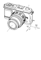
- FIG. 1 is an external view of a casing of a camera as an imaging device according to each embodiment.
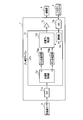
- FIG. 2 is a block diagram showing the overall configuration of a camera according to each embodiment.
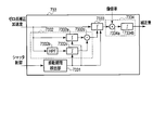
- FIG. 3 is a block diagram showing an internal configuration of the shake correction microcomputer according to the first embodiment.
- FIG. 4 is a diagram showing a schematic configuration of a translational shake correction unit.
- FIG. 5 is a diagram showing a detailed configuration of the translational shake correction unit in the first embodiment.
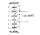
- FIG. 6 is a flowchart showing processing for calculating the image blur correction amount.
- FIG. 7 is a diagram showing the relationship between the shutter control signal and the acceleration.
- FIG. 8 is a flow chart showing a speed change estimation process in the first embodiment.
- FIG. 1 is an external view of a casing of a camera as an imaging device according to each embodiment.
- FIG. 2 is a block diagram showing the overall configuration of a camera according to each embodiment.
- FIG. 3 is a block diagram showing an internal configuration of the
- FIG. 9 is a diagram showing time change of a signal generated inside the translational shake correction unit.
- FIG. 10 is a diagram showing a detailed configuration of a translational shake correction unit in the second embodiment.
- FIG. 11 is a flow chart showing a speed change estimation process in the second embodiment.
- FIG. 12 is a diagram showing the relationship between the acceleration during the vibration period and the velocity as the integration result in the second embodiment.
- FIG. 13 is a diagram showing a detailed configuration of the translational shake correcting unit in the first modification of the second embodiment.
- FIG. 14 is a flowchart showing a speed change estimation process in the first modification.
- FIG. 15 is a diagram showing the relationship between the acceleration during the vibration period and the velocity as the integration result in the first modification.
- FIG. 16 is a flowchart of a speed change estimation process in the third modification.
- FIG. 17 is a flowchart showing an image shake correction process according to the fourth modification.
- FIG. 18 is a flowchart of the speed change estimation process in the fourth modification.
- FIG. 19 is a flowchart of the speed change estimation process in the fifth modification.
- FIG. 20 is a diagram showing a detailed configuration of the translational shake correction unit 733 in the third embodiment.
- FIG. 21 is a block diagram showing an internal configuration of the shake correction microcomputer according to the fourth embodiment.
- FIG. 22 is a block diagram showing details of the translational shake correction unit 733 in the fourth embodiment.
- FIG. 1 is an external view of a casing of a camera as an imaging device provided with a blur amount detection device according to each embodiment of the present invention.
- three orthogonal axes are defined for the camera housing 1.
- the axis of the case 1 which is the left-right direction when the user holds the case 1 of the camera in the horizontal position is taken as an X-axis.
- the right is the + direction
- the left is the ⁇ direction.
- the axis of the case 1 which is the vertical direction when the user holds the camera case 1 in the horizontal position is taken as a Y-axis.
- the upper side is the + direction
- the lower side is the ⁇ direction.
- an axis along the optical axis of the camera shown by a dashed dotted line in FIG. 1 is taken as a Z axis.
- the subject side (the front side of the housing 1) is the + direction
- the image side (the rear side of the housing 1) is the-direction.
- the X-axis and the Y-axis shown in FIG. 1 correspond to the X-axis and the Y-axis of the imaging surface of the imaging device 4 described later.
- the rotation direction around the X axis is taken as a pitch direction
- the rotation direction around the Y axis is taken as a yaw direction
- the rotation direction around the Z axis is taken as a roll direction.
- the direction of each arrow shown in FIG. 1 is taken as the + direction
- the opposite is taken as the ⁇ direction.
- the polarity of the direction described above depends on the mounting direction of the acceleration sensor 8 described later. Depending on the mounting direction of the acceleration sensor 8, the positive or negative direction may be different from that in FIG.
- FIG. 2 is a block diagram showing the overall configuration of a camera according to each embodiment of the present invention.
- An optical system 2 a focal plane shutter 3, an imaging device 4, a drive unit 5, a system controller 6, a motion compensation microcomputer (microcomputer) 7, and an acceleration in a camera 1 according to the present embodiment.
- a sensor 8, a release (switch) SW 9, and an electronic viewfinder (EVF) 10 are provided.
- the memory card 11 is provided inside the housing 1 or can be loaded into the housing 1.
- the optical system 2 has a single or a plurality of lenses and a stop, and forms a light flux from the outside of the housing 1 as an object image on the imaging surface of the imaging device 4.
- the focal plane shutter 3 is provided in front of the imaging surface of the imaging device 4 and performs an opening / closing operation to bring the imaging device 4 into an exposure state or a light shielding state.
- the imaging device 4 converts an object image formed on the imaging surface into an electrical signal based on an instruction from the system controller 6.
- the drive unit 5 has a support member for supporting the imaging device 4, and drives the imaging device 4 in the X-axis direction and the Y-axis direction based on an instruction from the shake correction microcomputer 7.
- the system controller 6 performs various controls related to the functions of the entire camera in addition to the above-described readout of the video signal. For example, the system controller 6 reads a video signal from the imaging device 4 and performs image processing for converting the read video signal into a format suitable for display or recording. Further, the system controller 6 controls the photographing operation when a second release switch of the release switch 9 described later is turned on. The photographing operation is a series of operations from driving the image pickup device 4 to obtain a video signal, processing the video signal into a format suitable for recording, and recording on the memory card 11. Further, at the time of the photographing operation, the system controller 6 also performs control related to the exposure of the imaging element 4 based on the external light beam incident through the optical system 2.
- the system controller 6 controls the opening time of the focal plane shutter 3 and the aperture value of the optical system 2. Furthermore, the system controller 6 monitors the image magnification of the optical system 2. For example, when the optical system 2 includes a zoom lens, the system controller 6 monitors the image magnification by the position of the zoom lens (the position corresponding to the focal length). In addition, the system controller 6 can also monitor whether the position corresponding to the focus (subject distance when focusing) of the lens constituting the optical system 2 has become the macro position (position corresponding to the close-up shooting). Monitor image magnification.
- the system controller 6 also controls image blur correction by communicating with the blur correction microcomputer 7.
- the shake correction microcomputer 7 controls the image shake correction operation according to the control of the system controller 6.
- the shake correction microcomputer 7 calculates an image shake correction amount from the output of the acceleration sensor 8, and inputs the calculated image shake correction amount to the drive unit 5.
- the drive unit 5 drives the imaging device 4 according to the image blur correction amount, it is possible to prevent an image blur which is a blur on the imaging surface of the imaging device 4.
- Such blur correction microcomputer 7 will be described in detail later.
- the acceleration sensor 8 detects the acceleration along the X axis and the Y axis shown in FIG.
- the signal of the acceleration detected by the acceleration sensor 8 is input to the shake correction microcomputer 7.
- the release switch (SW) 9 is a switch that operates in response to the release button provided on the housing 1.
- the release switch 9 has a first release switch that turns on in response to a half press of the release button, and a second release switch that turns on in response to a full press of the release button.
- the electronic view finder (EVF) 10 is, for example, a liquid crystal panel, and displays a video based on the video signal converted into a format displayable by the system controller 6 so that the user can visually recognize it.
- the memory card 11 is, for example, a flash memory, and records a video signal converted into a recordable format by the system controller 6.
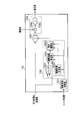
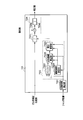
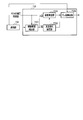
- FIG. 3 is a block diagram showing an internal configuration of the shake correction microcomputer 7 according to the first embodiment of the present invention.
- the shake correction microcomputer 7 has SIOs 71 a and 71 b, a driver 72, and a CPU 73.
- the shake correction microcomputer 7 shown in FIG. 3 only shows a configuration for correcting translational shake. This is to simplify the explanation. Of course, a configuration for correcting the angular deviation may be further provided.
- SIO 71 a and SIO 71 b are communication units for the CPU 73 to perform serial communication with other devices.
- the SIO 71 a is used for communication with the acceleration sensor 8.
- the SIO 71 b is also used for communication with the system controller 6.
- the driver 72 generates a signal for driving the drive unit 5 based on the image blur correction amount calculated by the CPU 73, and inputs the generated signal to the drive unit 5.
- the CPU 73 calculates an image shake correction amount for correcting translational shake of the housing 1 from the detection result of the acceleration sensor 8, and inputs the calculated image shake correction amount to the driver 72.
- the CPU 73 includes an acceleration acquisition unit 731, zero point correction units 732 a and 732 b, a translational shake correction unit 733, and a communication unit 734.
- the acceleration acquisition unit 731 reads the values of the accelerations of the two axes from the acceleration sensor 8 via the SIO 71a. Then, the acceleration acquiring unit 731 divides the read acceleration value into X and Y axis values and inputs the values to the translational shake correcting unit 733.
- the zero point correction units 732a and 732b subtract the acceleration signal level (zero point) acquired when the acceleration of the housing 1 becomes zero from the acceleration signal acquired by the acceleration acquisition unit 731 to obtain an acceleration acquisition unit.
- the offset component of the acceleration signal acquired at 731 is removed, and the acceleration zero point is adjusted to a predetermined reference value.
- the zero point correction unit 732a corrects the zero point of the X-axis acceleration.
- the zero point correction unit 732 b corrects the zero point of the Y-axis acceleration.
- the translational shake correction unit 733 calculates an image shake correction amount for correcting translational shake of the housing 1 based on the X-axis and Y-axis accelerations input from the zero point correction units 732 a and 732 b.
- the detailed configuration of the translational shake correction unit 733 will be described later.
- the communication unit 734 communicates with the system controller 6 via the SIO 71 b.
- FIG. 4 is a diagram showing a schematic configuration of the translational shake correction unit 733.
- FIG. 5 is a diagram showing a detailed configuration of the translational shake correction unit 733 in the first embodiment.
- the translational shake correction unit 733 in FIGS. 4 and 5 shows a configuration of one axis.
- the translational shake correcting unit 733 shown in FIGS. 4 and 5 is present on each of two axes of the X axis and the Y axis.
- the translational shake correction unit 733 includes a vibration period detection unit 7331, a speed change estimation unit 7332, a speed calculation unit 7333, and a shake amount calculation unit 7334.
- the vibration period detection unit 7331 detects the vibration period by communication with the system controller 6 via the communication unit 734.
- the vibration period is a period during which vibration equal to or greater than a predetermined threshold is applied.
- the predetermined threshold is a vibration that is larger than the vibration caused by the camera shake, and is a vibration caused by an operation of a movable portion such as the focal plane shutter 3, for example.
- the vibration period detection unit 7331 detects a vibration period according to, for example, a shutter control signal input from the system controller 6. Besides this, the vibration period may be measured experimentally.
- the velocity change estimation unit 7332 estimates the velocity change of the housing 1 during the vibration period based on the values of the zero point correction acceleration input from the zero point correction units 732a and 732b.
- the speed change estimation unit 7332 includes an integration unit 7332 a, a high pass filter (HPF) 7332 b, an integration unit 7332 c, and a subtraction unit 7332 d.
- HPF high pass filter
- the integrating unit 7332a integrates the zero point correction acceleration in the vibration period to calculate the velocity.
- the integration unit 7332a integrates only in the vibration period, and continues to output 0 in the other periods.
- the velocity calculated by the integration unit 7332a includes the velocity due to the vibration (camera shake) of the housing 1 itself and the velocity based on the vibration due to the operation of the movable portion such as the focal plane shutter 3 or the like.
- the HPF 733 b removes predetermined low frequency components in the zero point corrected acceleration during the vibration period.
- the cut-off frequency of the HPF 733 b is, for example, 20 Hz.
- the frequency of vibration due to camera shake is approximately 1 Hz to 10 Hz, and it is experimentally known that the frequency of vibration accompanying the operation of a movable portion such as the focal plane shutter 3 is approximately 50 Hz. Therefore, it is possible to extract only the acceleration component due to the operation of the movable part by removing the frequency component of 20 Hz or less, which is a frequency sufficiently higher than the frequency of vibration due to camera shake.
- the frequency component to be removed by the HPF 733 b may be a frequency that is higher than the upper limit frequency of vibration due to camera shake and lower than the lower limit frequency of vibration associated with the operation of the movable portion.
- the cutoff frequency is set to 20 Hz, but in practice it is preferable to consider the influence of the phase.
- the integrating unit 7332 c integrates the acceleration due to only the movement of the movable unit input from the HPF 7332 b to calculate the velocity.
- the integration unit 7332 c integrates only during the vibration period, and continues to output 0 during the other periods.
- the velocity calculated by the integrating unit 7332 c corresponds to the velocity offset erroneously calculated by the integrating unit 7332 a due to the vibration due to the movement of the movable portion.
- the subtracting unit 7332 d subtracts the velocity offset calculated by the integrating unit 7332 c from the velocity calculated by the integrating unit 7332 a to calculate a change in velocity caused only by the vibration (camera shake) of the housing 1.
- the velocity calculation unit 7333 includes an integration unit that calculates the velocity based on the accelerations input from the zero point correction units 732a and 732b. Furthermore, immediately after the vibration period, the velocity calculation unit 7333 performs correction to add the velocity change estimated by the velocity change estimation unit 7332 to the calculated velocity.
- the blur amount calculation unit 7334 calculates an image blur correction amount based on the speed obtained by the speed calculation unit 7333.
- the blur amount calculation unit 7334 has a multiplication unit 7334 a and an integration unit 7334 b.
- the multiplication unit 7334 a multiplies the speed calculated by the speed calculation unit 7333 by an image magnification obtained by communication with the system controller 6 via the communication unit 734 to obtain an image on the imaging surface of the imaging device 4. Calculate the translational velocity of
- the integrating unit 7334 b integrates the translational velocity of the image input from the multiplying unit 7334 a to calculate the translational movement amount of the image on the imaging surface of the imaging device 4 as the image blur correction amount.
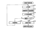
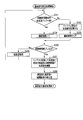
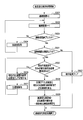
- FIG. 6 is a flowchart showing processing for calculating the image blur correction amount.
- the translational shake correction unit 733 obtains the value of acceleration via the zero point correction units 732a and 732b (step S1).
- the translational shake correction unit 733 determines whether or not the current vibration period is the vibration period by the vibration period detection unit 7331 (step S2).
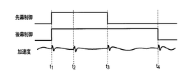
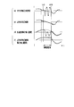
- FIG. 7 is a diagram showing the relationship between the shutter control signal and the acceleration.
- the shutter control signal in the case of the focal plane shutter is divided into a front curtain control signal and a rear curtain control signal.
- the front curtain control signal and the rear curtain control signal are control signals for controlling a magnet for attracting the front curtain and the rear curtain of the focal plane shutter.
- the control signal is High, a magnetic force is generated in the magnet.
- Timing t1 in FIG. 7 is timing at which the front and rear curtains of the focal plane shutter 3 are attracted. Acceleration is generated by the vibration at the timing t1.
- the timing t2 is a timing at which a lever for attracting the front and rear curtains of the focal plane shutter 3 is retracted. Acceleration is also generated by the vibration that occurs at this timing t2.
- These timings t1 and t2 are detected as vibration periods.
- the time interval from the timing t1 to the timing t2 is a fixed time interval. Therefore, timing t2 can be detected from timing t1 if the time interval between timing t1 and timing t2 which is the timing of rising of the leading and trailing curtain control signals is determined, for example, at the time of design of the camera.
- Timing t3 in FIG. 7 is the timing when the focal plane shutter 3 travels on the front curtain. Acceleration is also generated by the vibration generated when the front curtain travels at this timing t3. This timing t3 is also detected as a vibration period. In general, the timing t3 varies with the aperture setting. However, as can be seen from FIG. 7, timing t3 can be detected as the timing at which the leading curtain control signal changes to low.
- the timing t4 is a timing when the rear curtain of the focal plane shutter 3 travels. Acceleration is also generated by the vibration that occurs when the front curtain travels at this timing t4.
- the timing t4 is the timing of the end of the exposure period, and the vibration generated at this timing does not affect the photographed image. Therefore, it can be disregarded as a vibration period in this embodiment.
- the vibration due to the focal plane shutter 3 occurs due to its operation. Therefore, the vibration period can be determined from the levels of the front curtain control signal and the rear curtain control signal as shutter control signals. By detecting the vibration period using the shutter control signal, the vibration generated due to the operation of the focal plane shutter 3 can be detected regardless of the camera setting.
- step S2 If it is determined in step S2 that the period is not a vibration period, translational shake correction unit 733 calculates the velocity by integrating the acceleration by velocity calculation unit 7333 (step S3). On the other hand, when it is determined in S2 that the vibration period is determined, the translational shake correction unit 733 causes the velocity change estimation unit 7332 to estimate the velocity change during the vibration period (step S4).
- FIG. 8 is a flow chart showing a speed change estimation process in the first embodiment.
- the speed change estimation unit 7332 performs HPF (High Pass Filtering) processing on the signal of the zero point correction acceleration by the HPF 733 b (step S101).
- HPF High Pass Filtering
- the component related to camera shake in the signal of acceleration is removed, and only the component related to the movable part (focal plane shutter 3) is extracted.
- the speed change estimation unit 7332 integrates the zero point correction acceleration by the integration unit 7332a (step S102). Further, the speed change estimation unit 7332 integrates the acceleration subjected to the HPF processing by the integration unit 7332 c (step S103).
- the speed change estimation unit 7332 determines whether the vibration period has ended from the detection result of the vibration period detection unit 7331 (step S104).
- the speed change estimation unit 7332 acquires an acceleration (step S106). Thereafter, the speed change estimation unit 7332 repeats the processing of steps S101 to S104.
- the velocity change estimation unit 7332 subtracts the integral value of S103 from the integral value of S102 by the subtraction unit 7332d, and integrates the input from the subtraction unit 7332d by the velocity calculation unit 7333, The speed change based on the camera shake during the vibration period is calculated (step S105).
- the translational shake correction unit 733 calculates and corrects the speed by the speed calculation unit 7333 (step S5).
- the translational shake correction unit 733 multiplies the value of the velocity input from the velocity calculation unit 7333 by the image magnification by the multiplication unit 7334a of the shake amount calculation unit 7334 (step S6). Thereby, the translational velocity of the housing 1 is converted into the translational velocity of the image on the imaging plane. Then, the translational shake correction unit 733 integrates the value of the velocity input from the multiplication unit 7334 a to calculate the image shake correction amount (step S 7).
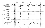
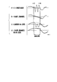
- FIG. 9 is a view showing time change of a signal generated inside the translational shake correction unit 733. As shown in FIG. As shown in (a) of FIG. 9, noise generated from the vibration of the movable portion is superimposed on the signal of the zero point correction acceleration, which is an input of the translational shake correction unit 733, from timing t1 to t4 which is a vibration period. Ru.
- the integration unit 7332a integrates the signal of the zero point correction acceleration input at each of the timings t1 to t3 which is a vibration period. Therefore, as shown in (b) of FIG. 9, the integration result at this time is obtained by integrating the acceleration component due to the vibration (camera shake) of the housing 1 and the integration of the acceleration component due to the vibration of the focal plane shutter 3 And both included.
- the HPF 733 b removes low frequency components of the input zero point corrected acceleration. Therefore, the output of the HPF 733 b is a signal of an acceleration component due to the vibration of the focal plane shutter 3 during the vibration period, as shown in (c) of FIG.
- the integration unit 7332 c integrates the input from the HPF 7332 b. Therefore, as shown in (d) of FIG. 9, the output of the integration unit 7332 c is the integration result of the acceleration component due to the vibration of the focal plane shutter 3 during the vibration period.
- the speed calculation unit 7333 integrates the input signal of the zero point correction acceleration except during the vibration period. On the other hand, at the end of the vibration period, the velocity calculation unit 7333 performs velocity correction in which the integration result of the acceleration component due to the vibration of the focal plane shutter 3 is subtracted from the integration result of the signal of the zero point correction acceleration. Therefore, the output of the speed calculation unit 7333 is as shown in (e) of FIG.
- the noise component generated from the vibration caused by the movement of the movable part by subtracting the noise component generated from the vibration caused by the movement of the movable part from the velocity obtained during the vibration period, the noise is generated in the acceleration generated from the vibration caused by the movement of the movable part. Even when it occurs, the effect is removed to calculate an accurate translational velocity, thereby calculating an accurate image blur correction amount.
- the integration unit 7332a and the velocity calculation unit 7333 are separated, and the operation of the velocity calculation unit 7333 is switched depending on whether or not it is a vibration period.
- the integration unit 7332a and the speed calculation unit 7333 may be integrated. In this case, at the end of the vibration period, the integration result of the integration unit 7332c is corrected to be subtracted from the integration result of the speed calculation unit 7333.
- FIG. 10 is a diagram showing a detailed configuration of the translational shake correction unit 733 in the second embodiment.
- the same components as in FIG. 5 are designated by the same reference numerals as in FIG.
- the second embodiment is different from the first embodiment in the configuration of the speed change estimation unit 7332. Therefore, the configuration and operation of the speed change estimation unit 7332 will be mainly described below.
- the speed change estimation unit 7332 in the second embodiment includes a buffer 73321, a duration measurement unit 73322, an interpolation straight line calculation unit 73323, and an integration calculation unit 73324.
- the buffer 73321 stores the acceleration at the time when the start of the vibration period is detected by the vibration period detection unit 7331.
- the duration measuring unit 73322 measures the duration from when the start of the vibration period is detected by the vibration period detecting unit 7331 to when the vibration period ends.
- the continuous period measurement unit 73322 is, for example, a counter that counts up by one each time the acquisition timing of acceleration passes from the time when the start of the vibration period is detected.
- the interpolation straight line calculation unit 73323 as an example of the interpolation unit stores the acceleration at the start of the vibration period and the time after the vibration period end stored in the buffer 73321 The interpolation point on the interpolation straight line indicating the acceleration during the vibration period is calculated using
- the integral calculation unit 73324 integrates the interpolation straight line calculated by the interpolation straight line calculation unit 73323 with the continuation period measured by the continuation period measurement unit 73322 to estimate the velocity change during the vibration period.
- FIG. 11 is a flow chart showing a speed change estimation process in the second embodiment.
- the speed change estimation unit 7332 determines whether or not the acceleration is stored in the buffer 73321 (step S201).
- the speed change estimation unit 7332 stores the input zero point correction acceleration in the buffer 73321 (step S202). Subsequently, the speed change estimation unit 7332 clears the value of the continuation period measured by the continuation period measurement unit 73322 to 0, and starts measurement of the continuation period (step S203).
- the velocity change estimation unit 7332 causes the duration measurement unit 73322 to count up the value of the duration (step S204).
- the speed change estimation unit 7332 determines again from the detection result of the vibration period detection unit 7331 whether or not the current time is a vibration period (step S205). If it is a vibration period, the speed change estimation unit 7332 acquires an acceleration (step S206). Thereafter, the speed change estimation unit 7332 repeats the processing of steps S201 to S205.
- the velocity change estimation unit 7332 causes the interpolation straight line calculation unit 73323 to use the acceleration stored in step S202, the duration period measured in step S204, and the current acceleration.
- the interpolation straight line which shows the acceleration change inside is calculated.
- the interpolation straight line is given by (Expression 1) (step S207).
- Acc_i [n] in (Expression 1) is a value of acceleration at the n-th interpolation position.
- Acc_b0 is the value of the acceleration stored in the buffer 73321.
- Acc_a0 is a value of (current) acceleration after the end of the vibration period.
- N is a duration in which the start point of the vibration period is 1. N is counted up each time the process of S204 is performed. n is the number of samples where the start point of the vibration period is 0.
- the speed change estimation unit 7332 integrates the interpolation straight line calculated by the interpolation straight line calculation unit 73323 by the integration calculation unit 73324 for the duration period measured in S204 to calculate an estimated value of the speed change (step S208). .
- This integral calculation is shown by (Equation 2).
- FIG. 12 is a diagram showing the relationship between the acceleration during the vibration period and the velocity as the integration result in the second embodiment.
- the acceleration during the vibration period includes not only the acceleration component due to the camera shake but also the acceleration component resulting from the vibration due to the operation of the movable part such as the focal plane shutter 3 or the like. Therefore, the acceleration during the vibration period is largely distorted in waveform as shown in (a) of FIG.
- the acceleration shown by the broken line in (a) of FIG. 12 indicates a state of only acceleration due to the vibration of the housing 1 when assuming that there is no acceleration component generated from the vibration due to the movement of the movable portion.
- the interpolation straight line calculation unit 73323 performs linear expression (straight line) interpolation of the acceleration during the vibration period using the accelerations at the sampling points before and after the vibration period.
- the black double circles in (b) of FIG. 12 indicate the acceleration used for the interpolation, and the black squares in FIG. 12 indicate the acceleration generated by the interpolation.
- the acceleration obtained by the linear interpolation is substantially equivalent to the state of only acceleration due to the vibration of the housing 1.
- (C) of FIG. 12 shows the velocity obtained by integrating the non-interpolated acceleration in the interpolation straight line calculation unit 73323. Since the velocity obtained in this case includes the one resulting from the vibration due to the operation of the movable portion, the waveform is greatly distorted.
- (D) of FIG. 12 shows the velocity obtained by integrating the acceleration after the interpolation in the interpolation straight line calculation unit 73323, that is, the output of the integration operation unit 73324.
- the velocity obtained after the end of the vibration period coincides with the velocity shown by the broken line in (c) of FIG.
- FIG. 13 is a diagram showing a detailed configuration of the translational shake correcting unit 733 in the first modification of the second embodiment.
- the same components as in FIG. 10 are designated by the same reference numerals as in FIG.
- the first modification differs in that the interpolation straight line calculation unit 73323 is replaced by an approximate curve calculation unit 73325.
- the buffer 73321 in the second embodiment stores only the acceleration at the start time of the vibration period
- the buffer 73321 of the first modification is different in storing the acceleration at a plurality of points in time.
- the buffer 73321 of the modification 1 stores the acceleration of one sample or plural samples at the start time of the vibration period as the front side acceleration. Furthermore, the buffer 73321 stores the acceleration of 0 samples or more after the end of the vibration period as the rear acceleration. In this case, the buffer 73321 stores 0 or more samples as the rear side acceleration because if the number of samples necessary as the rear side acceleration is 1 sample, the number of the rear side acceleration is sufficient if the current acceleration is obtained It is because it becomes a thing.
- the approximate curve calculation unit 73325 as another example of the interpolation unit uses the front acceleration and the rear acceleration stored in the buffer 73321 and the current acceleration when the acceleration of the required number of samples is stored in the buffer 73321. Then, an approximate curve indicating the acceleration of only the vibration component of the housing 1 during the vibration period is calculated.
- FIG. 14 is a flowchart showing a speed change estimation process in the first modification.
- the speed change estimation unit 7332 determines whether the front acceleration is stored in the buffer 73321 (step S301).
- the speed change estimation unit 7332 stores the input current zero point correction acceleration as the front side acceleration in the buffer 73321 (step S302). Subsequently, the speed change estimation unit 7332 clears the value of the continuation period measured by the continuation period measurement unit 73322 to 0 and starts measurement of the continuation period (step S303).
- the velocity change estimation unit 7332 causes the duration measurement unit 73322 to count up the value of the duration (step S304).
- the speed change estimation unit 7332 determines again from the detection result of the vibration period detection unit 7331 whether or not the current time is the vibration period (step S305). If it is a vibration period, the speed change estimation unit 7332 acquires an acceleration (step S306). Thereafter, the speed change estimation unit 7332 repeats the processing of steps S301 to S305.
- the speed change estimation unit 7332 confirms whether or not the acceleration of the number of samples necessary for calculation of the approximate curve is obtained (step S309). For example, in the case where the number of samples required as the rear side acceleration is one, if the current acceleration is acquired, the score of the rear side acceleration is sufficient. On the other hand, when the number of samples required as the rear acceleration is 2 or more and the rear acceleration excluding the current acceleration is not stored, the input current zero point correction acceleration is used as the rear acceleration in the buffer 73321. It memorizes (Step S310). Then, the speed change estimation unit 7332 obtains the acceleration again (step S311). Thereafter, the speed change estimation unit 7332 repeats steps S309 to S311 until the required number of backward samples can be acquired.
- the speed change estimation unit 7332 causes the approximate curve calculation unit 73325 to store the front side acceleration stored in step S302 and the duration period measured in step S304. And the rear side acceleration (including the current acceleration) stored in step S310 are used to calculate an approximate curve indicating the change in acceleration during the vibration period (step S312).
- Acc_i [n] in (Expression 4) is a value of acceleration at the n-th interpolation position.
- Acc_b1 is the value of the front side acceleration stored in the buffer 73321.
- Acc_b0 is the value of the rear side acceleration stored in the buffer 73321.
- Acc_a0 is the value of the current acceleration after the end of the vibration period.
- N is a continuation period where the start point of the vibration period is 0. N is counted up each time the process of S304 is performed.
- n is the number of samples where the start point of the vibration period is 0.
- the speed change estimation unit 7332 integrates the approximate curve calculated by the approximate curve calculation unit 73325 by the integration calculation unit 73324 for the duration period measured in S304 to calculate an estimated value of the speed change (step S313) .
- This integral calculation is shown by (Equation 5).
- the number of accelerations stored in the buffer 73321 is determined by the order of the approximate curve calculated by the approximate curve calculation unit 73325.
- the case where the order is 1 is similar to that of the second embodiment.
- the relationship between the sample number x of the front side acceleration required for calculation of the approximate curve and the sample number y of the rear side acceleration is, for example, as follows.
- One sample of the back acceleration is the current acceleration value.
- the number of back acceleration samples that need to be stored in buffer 73321 is y-1.
- the method of taking acceleration samples can be selected in various ways in accordance with the order of the polynomial that is the approximate curve.
- the order is an odd number, it is preferable to set the number of front acceleration samples greater than the number of rear acceleration samples. As a result, it is possible to accelerate the timing of returning to the normal speed calculation processing after the vibration period, and it is possible to further improve the speed calculation accuracy. Furthermore, it also reduces the release time lag.
- FIG. 15 is a diagram showing the relationship between the acceleration during the vibration period and the velocity as the integration result in the first modification.
- FIG. 15 is an example in which second-order polynomial interpolation is performed with the front acceleration as two samples and the rear acceleration as one sample.
- FIG. 15 uses polynomial interpolation, it is possible to obtain an approximate curve of acceleration that is more accurate than the linear interpolation of FIG. 12.
- Modification 2 of the Second Embodiment The modification 1 of the second embodiment calculates the approximate curve using polynomial interpolation. However, it is not necessary to use polynomial interpolation to calculate the approximate curve. Modification 2 is an example of calculating an approximate curve by the method of least squares.
- the acceleration detected by the acceleration sensor usually includes noise. Therefore, when the performance of the acceleration sensor is low and there are many noises included in the acceleration, sufficient accuracy may not be secured in the interpolation calculation for obtaining a curve which always passes the sampled acceleration point. In such a system, it is desirable to calculate the approximate curve by another method such as the least squares method.
- the order of the approximate curve and the number of samples to be used for calculation can be appropriately changed as in the interpolation calculation.
- the order of the approximate curve is L
- accelerations of L + 2 samples or more are used before and after the vibration period.
- Acc_i [n] in (Expression 7) is the value of the acceleration at the n-th interpolation position.
- Acc_b1 is the value of the front side acceleration immediately after the vibration period stored in the buffer 73321.
- Acc_b0 is a value of front side acceleration stored in the buffer 73321 one sample after immediately after the vibration period.
- Acc_a0 is the value of the rear acceleration stored in the buffer 73321 one sample after the end of the vibration period.
- Acc_a0 is the value of the rear acceleration (current acceleration) stored in the buffer 73321 two samples after the end of the vibration period.
- N is a continuation period where the start point of the vibration period is 0.
- N is counted up each time the process of S304 is performed.
- n is the number of samples where the start point of the vibration period is 0.
- the matrix M + is a pseudoinverse of the matrix M.
- FIG. 16 is a flowchart of a speed change estimation process in the third modification.
- FIG. 16 is the flowchart of FIG. 14 with the process of determining the approximate curve calculation method of step S400 added.
- the calculation method of the approximate curve can be determined using, for example, the shutter speed and the image magnification.
- the information on the shutter speed and the image magnification is information notified from the system controller 6 as a control unit.
- the first approximation is performed when the shutter speed is higher than 1/100 second
- the high order approximation is performed when the shutter speed is lower than 1/100 second.
- the image magnification is smaller than 1/10
- linear approximation is performed when the image magnification is smaller than 1/10
- high-order approximation is performed when the image magnification is 1/10 or more.
- the high-order approximate curve is an approximate curve calculated using two or more accelerations of either or both of the front side acceleration and the rear side acceleration.
- the shutter speed and the image magnification which serve as determination criteria for determining the approximate curve calculation method, also differ depending on the shapes of the optical system 2 and the housing 1 or the like. Thus, the decision criteria may be determined experimentally. Further, as the determination standard, both the shutter speed and the image magnification may be used, or only one may be used.
- interpolation can be performed at an appropriate calculation cost by performing the interpolation operation in accordance with the required accuracy of interpolation.
- the front side acceleration used to calculate the approximate curve is used at the vibration detection time (in fact, immediately after the vibration detection). However, in this case, detection may be delayed depending on the type of vibration. At this time, calculation of acceleration and velocity is performed using the information in the vibration period. As a countermeasure therefor, the acceleration before the vibration is detected may be stored in the buffer for a plurality of points, and the sample stored after the detection of the vibration may be used as the front acceleration to obtain an approximate curve.
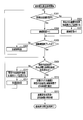
- FIG. 17 is a flowchart showing an image shake correction process according to the fourth modification.
- FIG. 18 is a flowchart of the speed change estimation process in the fourth modification.
- step S2 If it is determined in step S2 that the period is not a vibration period, translational shake correction unit 733 calculates the velocity by integrating the acceleration using velocity calculation unit 7333 (step S3). Subsequently, the translational shake correction unit 733 causes the buffer 73321 to store the accelerations of the plurality of samples for delay countermeasure (step S8).
- the number of acceleration samples stored in the buffer 73321 in step S8 is equal to or larger than the sum of the assumed number of vibration detection delay samples Z and the number of front acceleration samples x used for calculation of the approximate curve.
- the other processes are the same as those in FIG.
- the speed change estimation unit 7332 clears the value of the duration measured by the duration measurement unit 73322 to 0 (step S501). Next, the speed change estimation unit 7332 causes the duration measurement unit 73322 to count up the value of the duration (step S502).
- the speed change estimation unit 7332 determines whether the vibration period has ended from the detection result of the vibration period detection unit 7331 (step S503). If the vibration period has not ended, the speed change estimation unit 7332 acquires an acceleration (step S504). Thereafter, the speed change estimation unit 7332 repeats the processing of steps S502 to S503.
- the speed change estimation unit 7332 confirms whether or not the acceleration of the number of samples necessary for calculation of the approximate curve is obtained (step S505). For example, in the case where the number of samples required as the rear side acceleration is one, if the current acceleration is acquired, the score of the rear side acceleration is sufficient. On the other hand, when the number of samples required as the rear acceleration is two samples or more and the rear acceleration excluding the current acceleration is not stored, the input current zero point correction acceleration is used as the rear acceleration. It is stored in the buffer 73321 (step S506). Then, the speed change estimation unit 7332 acquires the acceleration again (step S507). Thereafter, the speed change estimation unit 7332 repeats steps S505 to S507 until the required number of backward samples can be acquired.
- the speed change estimation unit 7332 causes the approximate curve calculation unit 73325 to store the front side acceleration stored in step S8 and the duration period measured in step S502. And the rear side acceleration (including the current acceleration) stored in step S506 are used to calculate an approximate curve indicating the change in acceleration during the vibration period (step S508).
- Acc_i [n] (n + Z) / (N + 1 + Z) ⁇ (Acc_a0 ⁇ Acc_b0 [Z]) + Acc_b [Z] (Equation 9)
- Acc_i [n] in (Expression 9) is the value of the acceleration at the n-th interpolation position.
- Acc_b [Z] is the value of the front side acceleration stored in the buffer 73321 before detection of vibration.
- Acc_a0 is the value of the current acceleration after the end of the vibration period.
- N is a duration in which the start point of the vibration period is 1. N is counted up each time the process of step S502 is performed.
- n is the number of samples where the start point of the vibration period is 1.
- the speed change estimation unit 7332 integrates the approximate curve calculated by the approximate curve calculation unit 73325 by the integration calculation unit 73324 for the duration period measured in step S304 to calculate an estimated value of the speed change (step S509).
- This integral calculation is shown by (Equation 10).
- FIG. 19 is a flowchart of the speed change estimation process in the fifth modification.
- the vibration period (duration period) is equal to or less than a threshold (an experimental value, for example, 100 ms) based on the measurement result of the duration measurement unit. It determines (step S601). If the duration is equal to or less than the threshold, the speed change estimation unit 7332 performs the same processing as FIG. 18 thereafter. On the other hand, when the continuation period exceeds the threshold, the speed change estimation unit 7332 clears the integration result in the speed calculation unit 7333 (step S602). This clears the velocity change estimated value to zero.
- a threshold an experimental value, for example, 100 ms
- FIG. 20 is a diagram showing a detailed configuration of the translational shake correction unit 733 in the third embodiment.
- the same components as in FIG. 5 are designated by the same reference numerals as in FIG.
- the third embodiment is different in that a zero point correction acceleration detected via an acceleration sensor is also input to a vibration period detection unit 7331.
- the vibration period is detected using the control signal of the movable part such as the focal plane shutter 3 or the like.
- the detection method of the vibration period is not limited to this.
- the change in acceleration may be monitored by the vibration period detection unit 7331, and it may be determined that the vibration period is detected when a change in acceleration that is sufficiently larger than expected with normal camera shake is detected.
- the vibration period may be determined when the difference between the average of the acceleration of M samples and the current acceleration is equal to or more than a predetermined value.
- the vibration period may be detected by combining a plurality of methods.
- the operation of the movable portion such as the operation of the focal plane shutter 3, the charge operation of the flash device, the operation of the quick return mirror, and the operation of the diaphragm. It is also possible to detect, for example, vibrations caused by the handling of the user other than vibrations due to.
- the vibration generated by the user's handling includes the vibration generated in the case 1 by the user's operation such as the vibration generated when the user presses the release switch or the button or the vibration generated when the command dial is rotated, the camera strap
- the acceleration is integrated twice to calculate the image blur correction amount.
- the acceleration detected by the acceleration sensor 8 is zero-point corrected, but the gravity of the gravity between the reference value of the actual acceleration sensor 8 and the zero point corrected by the zero-point correction units 732 a and 732 b If there is an error other than the influence, the two integrations increase the error. If integration is continued for a long time in such a state, the difference between the image blur correction amount to be actually obtained and the calculated image blur correction amount will be large. Therefore, it is desirable not to integrate the calculated velocity as it is, but to calculate the velocity from the angular velocity detected by the angular velocity sensor.
- FIG. 21 is a block diagram showing an internal configuration of the shake correction microcomputer 7 in the fourth embodiment.
- the shake correction microcomputer 7 according to the fourth embodiment has ADCs (analog / digital converters) 74a and 74b in addition to the SIOs 71a and 71b, the driver 72, and the CPU 73.
- the CPU 73 further includes zero point correction units 735a and 735b.
- the ADCs 74a and 74b are connected to the angular velocity sensors 12a and 12b.
- the angular velocity sensors 12 a and 12 b detect the angular velocity around the axis set in the housing 1.
- the angular velocity sensor 12a detects an angular velocity in the pitch direction.
- the angular velocity sensor 12 b detects an angular velocity in the yaw direction.
- the ADC 74a converts the output signal of the angular velocity sensor 12a into a digital signal.
- the ADC 74 b converts the output signal of the angular velocity sensor 12 b into a digital signal.
- the zero point correction units 735a and 735b remove the offset component by subtracting the signal level (zero point) acquired when the angular velocity of the housing 1 becomes zero from the angular velocity signal acquired by the angular velocity sensor. , The angular velocity zero point is adjusted to a predetermined reference value.
- the zero point correction unit 735a corrects the zero point of the pitch direction angular velocity.
- the zero point correction unit 735b corrects the zero point of the yaw direction acceleration.
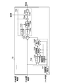
- FIG. 22 is a block diagram showing details of the translational shake correction unit 733 in the fourth embodiment.
- FIG. 22 is a block diagram of only one axis.
- a translational shake correction unit 733 having a configuration shown in FIG. 22 is present on each of two axes of the X axis and the Y axis.
- the example of FIG. 22 is an example in which the angular velocity of one axis is made to correspond to the acceleration of one axis.
- a method of making the angular velocity of two axes correspond to the acceleration of one axis is also proposed and known. This method can also be used in the present embodiment.
- FIG. 22 the same components as in FIG. 10 are designated by the same reference numerals as in FIG.
- the configuration of translational shake correction unit 733 shown in FIG. 22 is different from the configuration of translational shake correction unit 733 shown in FIG. 10 in the configuration of shake amount calculation unit 7334.
- differences from FIG. 10 will be mainly described.
- the blur amount calculation unit 7334 in the fourth embodiment includes filters 7334 c and 7334 d, a radius calculation unit 7334 e, and a multiplication unit 7334 f in addition to the multiplication unit 7334 a and the integration unit 7334 b.
- filters 7334 c and 7334 d the blur amount calculation unit 7334 in the fourth embodiment includes filters 7334 c and 7334 d, a radius calculation unit 7334 e, and a multiplication unit 7334 f in addition to the multiplication unit 7334 a and the integration unit 7334 b.
- the filter 7334 c is a filter that adjusts the frequency characteristic and the phase characteristic of the signal of the velocity obtained by the velocity calculation unit 7333.
- filter 7334c is an HPF that removes low frequency components in the velocity signal.
- the frequency of camera shake is generally about 1 Hz to 10 Hz. Therefore, by removing the frequency of 1 Hz or less by the filter 7334c, the influence of temperature drift or the like on the signal of the acceleration detected by the acceleration sensor is removed.
- the filter 7334 d is a filter that adjusts the frequency characteristic and the phase characteristic of the zero point correction angular velocity input from the ADC.
- the filter 7334 d has a role of matching the frequency characteristic and the phase characteristic of the signal of the velocity obtained by the velocity calculation unit 7333 and the signal of the angular velocity detected through the angular velocity sensor.
- the filter 7334d adjusts the frequency characteristic and the phase characteristic of the angular velocity signal so that the frequency characteristic and the phase characteristic of the velocity signal have the same characteristic. Do.
- the radius calculation unit 7334 e divides the output of the filter 7334 c by the output of the filter 7334 d to calculate the rotation radius. Because of division, when the absolute value of the output of the filter 7334 d is close to 0, the calculated value of the radius diverges to infinity. In this case, the radius can not be calculated with sufficient accuracy. Therefore, when the output of the filter 7334 d is equal to or less than a predetermined value, the radius calculating unit 7334 e fixes the output without performing a new division. In addition, when the vibration period is detected by the vibration period detection unit 7331, there is a possibility that the velocity obtained by the speed calculation unit 7333 includes a component due to the vibration of the movable portion or the like. Therefore, even when the vibration period is detected by the vibration period detection unit 7331, the radius calculation unit 7334e does not update the output.
- the multiplying unit 7334 f calculates a translational velocity by multiplying the radius calculation value input from the radius calculating unit 7334 e by the angular velocity input from the ADC.
- the radius of rotation is determined from the ratio of the angular velocity to the translational velocity, and the final translational velocity is calculated from the determined radius of rotation.
- Several methods for calculating the translational velocity of the housing using an angular velocity sensor have been proposed. Other than the method described in the present embodiment, any calculation method that uses the integrated value of acceleration in the calculation process can be applied.
- the second embodiment uses an acceleration sensor to calculate the translational velocity
- the fourth embodiment uses an acceleration sensor and an angular velocity sensor to calculate the translational velocity.
- the fifth embodiment is an example in which the moving velocity of an image obtained by calculating a motion vector is used for calculating the translational velocity.
- the system controller 6 when the camera is in through image display, information obtained by the imaging device 4 is processed by the system controller 6 and used for display.
- the system controller 6 in the present embodiment also calculates a motion vector using information obtained by the imaging device during live view display. It is possible to use the calculated motion vector as the image blur correction amount.
- the image sensor 4 is shielded by the focal plane shutter 3. This makes it impossible to calculate motion vectors.
- the translational velocity is calculated using the input from the acceleration sensor or the angular velocity sensor described in each of the above-described embodiments and their modifications.
Landscapes
- Engineering & Computer Science (AREA)
- Multimedia (AREA)
- Signal Processing (AREA)
- Adjustment Of Camera Lenses (AREA)
- Studio Devices (AREA)
Abstract
La présente invention se rapporte à un dispositif de détection de quantité d'agitation qui comprend : un capteur d'accélération (8) ; une unité de détection de période de vibrations (7331) ; une unité d'estimation de changement de vitesse (7332) ; une unité de calcul de vitesse (7333) ; et une unité de calcul de quantité d'agitation (7334). Le capteur d'accélération (8) détecte l'accélération du boîtier. L'unité de détection de période de vibrations (7331) détecte une période pendant laquelle des vibrations supérieures à un seul préconisé, agissent sur le boîtier. L'unité d'estimation de changement de vitesse (7332) estime un changement de la vitesse du boîtier pendant la période de vibrations sur la base de l'accélération détectée par le capteur d'accélération (8). L'unité de calcul de vitesse (7333) calcule la vitesse du boîtier sur la base de l'accélération et corrige la vitesse sur la base du changement de vitesse estimé par l'unité d'estimation de changement de vitesse (7332). L'unité de calcul de quantité d'agitation (7334) calcule une quantité d'agitation d'image (7334) pour les vibrations appliquées au boîtier sur la base de la vitesse corrigée par l'unité de calcul de vitesse (7333)
Priority Applications (3)
| Application Number | Priority Date | Filing Date | Title |
|---|---|---|---|
| EP14757437.0A EP2963491B1 (fr) | 2013-02-28 | 2014-02-17 | Dispositif de détection de quantité d'agitation et dispositif d'imagerie |
| CN201480010156.6A CN105074562B (zh) | 2013-02-28 | 2014-02-17 | 抖动量检测装置和摄像装置 |
| US14/837,357 US9525820B2 (en) | 2013-02-28 | 2015-08-27 | Shake amount detection device and imaging device |
Applications Claiming Priority (2)
| Application Number | Priority Date | Filing Date | Title |
|---|---|---|---|
| JP2013-039551 | 2013-02-28 | ||
| JP2013039551A JP6091255B2 (ja) | 2013-02-28 | 2013-02-28 | ブレ量検出装置及び撮像装置 |
Related Child Applications (1)
| Application Number | Title | Priority Date | Filing Date |
|---|---|---|---|
| US14/837,357 Continuation US9525820B2 (en) | 2013-02-28 | 2015-08-27 | Shake amount detection device and imaging device |
Publications (1)
| Publication Number | Publication Date |
|---|---|
| WO2014132827A1 true WO2014132827A1 (fr) | 2014-09-04 |
Family
ID=51428099
Family Applications (1)
| Application Number | Title | Priority Date | Filing Date |
|---|---|---|---|
| PCT/JP2014/053656 WO2014132827A1 (fr) | 2013-02-28 | 2014-02-17 | Dispositif de détection de quantité d'agitation et dispositif d'imagerie |
Country Status (5)
| Country | Link |
|---|---|
| US (1) | US9525820B2 (fr) |
| EP (1) | EP2963491B1 (fr) |
| JP (1) | JP6091255B2 (fr) |
| CN (1) | CN105074562B (fr) |
| WO (1) | WO2014132827A1 (fr) |
Cited By (2)
| Publication number | Priority date | Publication date | Assignee | Title |
|---|---|---|---|---|
| CN104469357A (zh) * | 2014-12-30 | 2015-03-25 | 中国科学院长春光学精密机械与物理研究所 | 微振动对长焦距相机成像质量影响的测试系统 |
| WO2016194307A1 (fr) * | 2015-05-29 | 2016-12-08 | Canon Kabushiki Kaisha | Dispositif de correction de secousse, appareil de capture d'image et procédé de correction de secousse |
Families Citing this family (16)
| Publication number | Priority date | Publication date | Assignee | Title |
|---|---|---|---|---|
| US10602082B2 (en) | 2014-09-17 | 2020-03-24 | Fluke Corporation | Triggered operation and/or recording of test and measurement or imaging tools |
| WO2016065261A1 (fr) | 2014-10-24 | 2016-04-28 | Fluke Corporation | Système d'imagerie utilisant des caméras infrarouge fixes, modulaires, mobiles et portables ayant la capacité de recevoir, de communiquer et d'afficher des données et des images au moyen d'une détection de proximité |
| US9906726B2 (en) * | 2015-04-22 | 2018-02-27 | Canon Kabushiki Kaisha | Image stabilization control apparatus, optical apparatus and storage medium storing image stabilizing control program |
| US20170078544A1 (en) | 2015-09-16 | 2017-03-16 | Fluke Corporation | Electrical isolation for a camera in a test and measurement tool |
| JP2017078760A (ja) * | 2015-10-20 | 2017-04-27 | リコーイメージング株式会社 | 撮影装置及び撮影方法 |
| WO2017070629A1 (fr) | 2015-10-23 | 2017-04-27 | Fluke Corporation | Outil d'imagerie pour analyse de vibration et/ou de défaut d'alignement |
| US9922428B2 (en) | 2016-08-19 | 2018-03-20 | Crystal Instruments Corporation | Vibration image acquisition and processing |
| JP6880979B2 (ja) | 2016-11-30 | 2021-06-02 | 株式会社リコー | 振動抑制装置および電子機器 |
| JP7057628B2 (ja) * | 2017-01-26 | 2022-04-20 | Omデジタルソリューションズ株式会社 | 撮像装置、及び、その像ぶれ量算出方法 |
| CN108881703B (zh) * | 2017-05-09 | 2020-07-21 | 杭州海康威视数字技术股份有限公司 | 防抖控制方法和装置 |
| CN107728472B (zh) * | 2017-09-04 | 2020-09-25 | 中国科学院光电技术研究所 | 一种基于单加速度计的快反镜扰动观测补偿控制方法 |
| WO2019176020A1 (fr) | 2018-03-14 | 2019-09-19 | 株式会社ソニー・インタラクティブエンタテインメント | Dispositif et procédé d'estimation de position, et programme |
| CN110235431B (zh) * | 2019-04-30 | 2021-08-24 | 深圳市大疆创新科技有限公司 | 电子增稳方法、图像采集设备、可移动平台 |
| JP7281957B2 (ja) * | 2019-05-07 | 2023-05-26 | キヤノン株式会社 | 防振制御装置及び方法、及び撮像システム |
| WO2021044585A1 (fr) * | 2019-09-05 | 2021-03-11 | オリンパス株式会社 | Dispositif d'imagerie, système, procédé de correction de flou d'image, programme et support d'enregistrement |
| JP7395340B2 (ja) * | 2019-12-09 | 2023-12-11 | 特許機器株式会社 | 測定器、測定システム及び測定方法 |
Citations (6)
| Publication number | Priority date | Publication date | Assignee | Title |
|---|---|---|---|---|
| JPH07225405A (ja) | 1993-12-14 | 1995-08-22 | Nikon Corp | 像振れ補正カメラ |
| JP2897413B2 (ja) | 1990-11-16 | 1999-05-31 | ミノルタ株式会社 | ぶれ検出機能付カメラ |
| JP2007218976A (ja) * | 2006-02-14 | 2007-08-30 | Nikon Corp | カメラシステム、レンズ鏡筒およびカメラ |
| JP2008151822A (ja) * | 2006-12-14 | 2008-07-03 | Pentax Corp | 像ブレ補正装置 |
| JP2010025962A (ja) * | 2008-07-15 | 2010-02-04 | Canon Inc | 防振制御装置及び撮像装置 |
| JP2011059429A (ja) * | 2009-09-10 | 2011-03-24 | Nikon Corp | ブレ補正装置および光学機器 |
Family Cites Families (9)
| Publication number | Priority date | Publication date | Assignee | Title |
|---|---|---|---|---|
| JPH04277728A (ja) * | 1991-03-06 | 1992-10-02 | Nikon Corp | カメラの防振装置 |
| JP4667052B2 (ja) * | 2005-01-27 | 2011-04-06 | キヤノン株式会社 | 撮像装置並びにそのカメラ本体及び交換レンズ |
| JP4981325B2 (ja) * | 2006-02-13 | 2012-07-18 | キヤノン株式会社 | カメラシステム |
| US7929848B2 (en) | 2006-02-14 | 2011-04-19 | Nikon Corporation | Vibration detection device, optical device, and method of operation of vibration detection device |
| JP4315204B2 (ja) * | 2007-02-21 | 2009-08-19 | ソニー株式会社 | 振動検出装置、撮像装置、振動検出方法 |
| JP2009008858A (ja) * | 2007-06-27 | 2009-01-15 | Olympus Imaging Corp | ブレ補正装置及び撮像装置 |
| JP5188138B2 (ja) * | 2007-10-15 | 2013-04-24 | キヤノン株式会社 | 像ぶれ補正装置を有する光学機器 |
| JP5274130B2 (ja) * | 2008-07-15 | 2013-08-28 | キヤノン株式会社 | 像振れ補正装置及び光学機器、撮像装置並びに像振れ補正装置の制御方法 |
| JP5031690B2 (ja) * | 2008-07-15 | 2012-09-19 | キヤノン株式会社 | 防振制御装置及び撮像装置並びに防振制御装置の制御方法 |
-
2013
- 2013-02-28 JP JP2013039551A patent/JP6091255B2/ja active Active
-
2014
- 2014-02-17 CN CN201480010156.6A patent/CN105074562B/zh not_active Expired - Fee Related
- 2014-02-17 EP EP14757437.0A patent/EP2963491B1/fr active Active
- 2014-02-17 WO PCT/JP2014/053656 patent/WO2014132827A1/fr active Application Filing
-
2015
- 2015-08-27 US US14/837,357 patent/US9525820B2/en active Active
Patent Citations (6)
| Publication number | Priority date | Publication date | Assignee | Title |
|---|---|---|---|---|
| JP2897413B2 (ja) | 1990-11-16 | 1999-05-31 | ミノルタ株式会社 | ぶれ検出機能付カメラ |
| JPH07225405A (ja) | 1993-12-14 | 1995-08-22 | Nikon Corp | 像振れ補正カメラ |
| JP2007218976A (ja) * | 2006-02-14 | 2007-08-30 | Nikon Corp | カメラシステム、レンズ鏡筒およびカメラ |
| JP2008151822A (ja) * | 2006-12-14 | 2008-07-03 | Pentax Corp | 像ブレ補正装置 |
| JP2010025962A (ja) * | 2008-07-15 | 2010-02-04 | Canon Inc | 防振制御装置及び撮像装置 |
| JP2011059429A (ja) * | 2009-09-10 | 2011-03-24 | Nikon Corp | ブレ補正装置および光学機器 |
Non-Patent Citations (1)
| Title |
|---|
| See also references of EP2963491A4 |
Cited By (4)
| Publication number | Priority date | Publication date | Assignee | Title |
|---|---|---|---|---|
| CN104469357A (zh) * | 2014-12-30 | 2015-03-25 | 中国科学院长春光学精密机械与物理研究所 | 微振动对长焦距相机成像质量影响的测试系统 |
| WO2016194307A1 (fr) * | 2015-05-29 | 2016-12-08 | Canon Kabushiki Kaisha | Dispositif de correction de secousse, appareil de capture d'image et procédé de correction de secousse |
| JP2016224204A (ja) * | 2015-05-29 | 2016-12-28 | キヤノン株式会社 | ブレ補正装置、光学機器、撮像装置、ブレ補正方法 |
| US10222679B2 (en) | 2015-05-29 | 2019-03-05 | Canon Kabushiki Kaisha | Shake correction device, image pickup apparatus, and shake correction method |
Also Published As
| Publication number | Publication date |
|---|---|
| US9525820B2 (en) | 2016-12-20 |
| CN105074562B (zh) | 2018-03-20 |
| US20150365598A1 (en) | 2015-12-17 |
| EP2963491B1 (fr) | 2017-10-04 |
| EP2963491A1 (fr) | 2016-01-06 |
| JP6091255B2 (ja) | 2017-03-08 |
| EP2963491A4 (fr) | 2016-08-24 |
| CN105074562A (zh) | 2015-11-18 |
| JP2014168171A (ja) | 2014-09-11 |
Similar Documents
| Publication | Publication Date | Title |
|---|---|---|
| WO2014132827A1 (fr) | Dispositif de détection de quantité d'agitation et dispositif d'imagerie | |
| JP5094606B2 (ja) | 像振れ補正装置およびそれを備えた光学機器、撮像装置、像振れ補正装置の制御方法 | |
| JP5274130B2 (ja) | 像振れ補正装置及び光学機器、撮像装置並びに像振れ補正装置の制御方法 | |
| JP6362556B2 (ja) | 制御装置、撮像装置、制御方法、プログラム、および、記憶媒体 | |
| US7634178B2 (en) | Image stabilizing apparatus and image pickup apparatus | |
| US9170429B2 (en) | Optical apparatus and image capturing apparatus, and method of controlling the same and storage medium | |
| JP5965770B2 (ja) | ブレ量検出装置、撮像装置及びブレ量検出方法 | |
| JP2017090580A (ja) | 像ブレ補正装置及び方法 | |
| JP2017092616A (ja) | 像ブレ補正装置及び方法 | |
| JP2015031780A (ja) | 像振れ補正装置およびその制御方法、レンズ鏡筒、光学機器、並びに撮像装置 | |
| JP6995561B2 (ja) | 像ブレ補正装置およびその制御方法、撮像装置 | |
| WO2018030166A1 (fr) | Dispositif et procédé de correction de tremblement d'image et dispositif optique | |
| JP5977611B2 (ja) | ブレ量検出装置、撮像装置及びブレ量検出方法 | |
| JP3800709B2 (ja) | ブレ補正装置、光学装置、及び、ブレ補正方法 | |
| JP5460135B2 (ja) | 光学機器 | |
| JP2012163824A (ja) | ブレ補正装置及び光学機器 | |
| JP6024031B2 (ja) | ブレ補正装置及び光学機器 | |
| JP6759608B2 (ja) | 撮像装置 | |
| JP6476701B2 (ja) | 撮像装置、レンズの位置ずれ補正方法及びプログラム | |
| JP2014126859A (ja) | 撮像装置及びその制御方法、プログラム、記憶媒体 | |
| JP6268981B2 (ja) | ブレ補正装置、交換レンズ及びカメラ | |
| JP5693656B2 (ja) | 像振れ補正装置およびそれを備えた光学機器、撮像装置、像振れ補正装置の制御方法 | |
| JP2018197772A (ja) | 像ブレ補正装置、レンズ装置、撮像装置、像ブレ補正装置の制御方法、プログラム、および、記憶媒体 | |
| JP5420042B2 (ja) | 像振れ補正装置及びそれを具備する光学機器、撮像装置、ならびに像振れ補正装置の制御方法 | |
| JP2019092037A (ja) | 撮像装置およびその制御方法 |
Legal Events
| Date | Code | Title | Description |
|---|---|---|---|
| WWE | Wipo information: entry into national phase |
Ref document number: 201480010156.6 Country of ref document: CN |
|
| 121 | Ep: the epo has been informed by wipo that ep was designated in this application |
Ref document number: 14757437 Country of ref document: EP Kind code of ref document: A1 |
|
| NENP | Non-entry into the national phase |
Ref country code: DE |
|
| REEP | Request for entry into the european phase |
Ref document number: 2014757437 Country of ref document: EP |
|
| WWE | Wipo information: entry into national phase |
Ref document number: 2014757437 Country of ref document: EP |