WO2014132598A1 - 発泡性射出成形体の製造方法及びその射出装置 - Google Patents
発泡性射出成形体の製造方法及びその射出装置 Download PDFInfo
- Publication number
- WO2014132598A1 WO2014132598A1 PCT/JP2014/000876 JP2014000876W WO2014132598A1 WO 2014132598 A1 WO2014132598 A1 WO 2014132598A1 JP 2014000876 W JP2014000876 W JP 2014000876W WO 2014132598 A1 WO2014132598 A1 WO 2014132598A1
- Authority
- WO
- WIPO (PCT)
- Prior art keywords
- injection
- screw
- molten resin
- heating cylinder
- foaming gas
- Prior art date
Links
Images


Classifications
-
- B—PERFORMING OPERATIONS; TRANSPORTING
- B29—WORKING OF PLASTICS; WORKING OF SUBSTANCES IN A PLASTIC STATE IN GENERAL
- B29C—SHAPING OR JOINING OF PLASTICS; SHAPING OF MATERIAL IN A PLASTIC STATE, NOT OTHERWISE PROVIDED FOR; AFTER-TREATMENT OF THE SHAPED PRODUCTS, e.g. REPAIRING
- B29C44/00—Shaping by internal pressure generated in the material, e.g. swelling or foaming ; Producing porous or cellular expanded plastics articles
- B29C44/34—Auxiliary operations
- B29C44/3442—Mixing, kneading or conveying the foamable material
- B29C44/3446—Feeding the blowing agent
-
- B—PERFORMING OPERATIONS; TRANSPORTING
- B29—WORKING OF PLASTICS; WORKING OF SUBSTANCES IN A PLASTIC STATE IN GENERAL
- B29C—SHAPING OR JOINING OF PLASTICS; SHAPING OF MATERIAL IN A PLASTIC STATE, NOT OTHERWISE PROVIDED FOR; AFTER-TREATMENT OF THE SHAPED PRODUCTS, e.g. REPAIRING
- B29C44/00—Shaping by internal pressure generated in the material, e.g. swelling or foaming ; Producing porous or cellular expanded plastics articles
- B29C44/34—Auxiliary operations
- B29C44/36—Feeding the material to be shaped
- B29C44/38—Feeding the material to be shaped into a closed space, i.e. to make articles of definite length
- B29C44/42—Feeding the material to be shaped into a closed space, i.e. to make articles of definite length using pressure difference, e.g. by injection or by vacuum
- B29C44/421—Feeding the material to be shaped into a closed space, i.e. to make articles of definite length using pressure difference, e.g. by injection or by vacuum by plastizising the material into a shot cavity and injecting using a plunger
-
- B—PERFORMING OPERATIONS; TRANSPORTING
- B29—WORKING OF PLASTICS; WORKING OF SUBSTANCES IN A PLASTIC STATE IN GENERAL
- B29C—SHAPING OR JOINING OF PLASTICS; SHAPING OF MATERIAL IN A PLASTIC STATE, NOT OTHERWISE PROVIDED FOR; AFTER-TREATMENT OF THE SHAPED PRODUCTS, e.g. REPAIRING
- B29C45/00—Injection moulding, i.e. forcing the required volume of moulding material through a nozzle into a closed mould; Apparatus therefor
- B29C45/0053—Injection moulding, i.e. forcing the required volume of moulding material through a nozzle into a closed mould; Apparatus therefor combined with a final operation, e.g. shaping
- B29C45/0055—Shaping
-
- B—PERFORMING OPERATIONS; TRANSPORTING
- B29—WORKING OF PLASTICS; WORKING OF SUBSTANCES IN A PLASTIC STATE IN GENERAL
- B29C—SHAPING OR JOINING OF PLASTICS; SHAPING OF MATERIAL IN A PLASTIC STATE, NOT OTHERWISE PROVIDED FOR; AFTER-TREATMENT OF THE SHAPED PRODUCTS, e.g. REPAIRING
- B29C45/00—Injection moulding, i.e. forcing the required volume of moulding material through a nozzle into a closed mould; Apparatus therefor
- B29C45/02—Transfer moulding, i.e. transferring the required volume of moulding material by a plunger from a "shot" cavity into a mould cavity
-
- B—PERFORMING OPERATIONS; TRANSPORTING
- B29—WORKING OF PLASTICS; WORKING OF SUBSTANCES IN A PLASTIC STATE IN GENERAL
- B29C—SHAPING OR JOINING OF PLASTICS; SHAPING OF MATERIAL IN A PLASTIC STATE, NOT OTHERWISE PROVIDED FOR; AFTER-TREATMENT OF THE SHAPED PRODUCTS, e.g. REPAIRING
- B29C45/00—Injection moulding, i.e. forcing the required volume of moulding material through a nozzle into a closed mould; Apparatus therefor
- B29C45/17—Component parts, details or accessories; Auxiliary operations
- B29C45/1701—Component parts, details or accessories; Auxiliary operations using a particular environment during moulding, e.g. moisture-free or dust-free
-
- B—PERFORMING OPERATIONS; TRANSPORTING
- B29—WORKING OF PLASTICS; WORKING OF SUBSTANCES IN A PLASTIC STATE IN GENERAL
- B29C—SHAPING OR JOINING OF PLASTICS; SHAPING OF MATERIAL IN A PLASTIC STATE, NOT OTHERWISE PROVIDED FOR; AFTER-TREATMENT OF THE SHAPED PRODUCTS, e.g. REPAIRING
- B29C45/00—Injection moulding, i.e. forcing the required volume of moulding material through a nozzle into a closed mould; Apparatus therefor
- B29C45/17—Component parts, details or accessories; Auxiliary operations
- B29C45/1703—Introducing an auxiliary fluid into the mould
-
- B—PERFORMING OPERATIONS; TRANSPORTING
- B29—WORKING OF PLASTICS; WORKING OF SUBSTANCES IN A PLASTIC STATE IN GENERAL
- B29C—SHAPING OR JOINING OF PLASTICS; SHAPING OF MATERIAL IN A PLASTIC STATE, NOT OTHERWISE PROVIDED FOR; AFTER-TREATMENT OF THE SHAPED PRODUCTS, e.g. REPAIRING
- B29C45/00—Injection moulding, i.e. forcing the required volume of moulding material through a nozzle into a closed mould; Apparatus therefor
- B29C45/17—Component parts, details or accessories; Auxiliary operations
- B29C45/46—Means for plasticising or homogenising the moulding material or forcing it into the mould
- B29C45/47—Means for plasticising or homogenising the moulding material or forcing it into the mould using screws
- B29C45/50—Axially movable screw
- B29C45/5092—Intrusion moulding, i.e. the screw rotates during injection
-
- B—PERFORMING OPERATIONS; TRANSPORTING
- B29—WORKING OF PLASTICS; WORKING OF SUBSTANCES IN A PLASTIC STATE IN GENERAL
- B29C—SHAPING OR JOINING OF PLASTICS; SHAPING OF MATERIAL IN A PLASTIC STATE, NOT OTHERWISE PROVIDED FOR; AFTER-TREATMENT OF THE SHAPED PRODUCTS, e.g. REPAIRING
- B29C45/00—Injection moulding, i.e. forcing the required volume of moulding material through a nozzle into a closed mould; Apparatus therefor
- B29C45/17—Component parts, details or accessories; Auxiliary operations
- B29C45/46—Means for plasticising or homogenising the moulding material or forcing it into the mould
- B29C45/53—Means for plasticising or homogenising the moulding material or forcing it into the mould using injection ram or piston
- B29C45/54—Means for plasticising or homogenising the moulding material or forcing it into the mould using injection ram or piston and plasticising screw
-
- B—PERFORMING OPERATIONS; TRANSPORTING
- B29—WORKING OF PLASTICS; WORKING OF SUBSTANCES IN A PLASTIC STATE IN GENERAL
- B29C—SHAPING OR JOINING OF PLASTICS; SHAPING OF MATERIAL IN A PLASTIC STATE, NOT OTHERWISE PROVIDED FOR; AFTER-TREATMENT OF THE SHAPED PRODUCTS, e.g. REPAIRING
- B29C45/00—Injection moulding, i.e. forcing the required volume of moulding material through a nozzle into a closed mould; Apparatus therefor
- B29C45/17—Component parts, details or accessories; Auxiliary operations
- B29C45/1701—Component parts, details or accessories; Auxiliary operations using a particular environment during moulding, e.g. moisture-free or dust-free
- B29C2045/1702—Component parts, details or accessories; Auxiliary operations using a particular environment during moulding, e.g. moisture-free or dust-free dissolving or absorbing a fluid in the plastic material
-
- B—PERFORMING OPERATIONS; TRANSPORTING
- B29—WORKING OF PLASTICS; WORKING OF SUBSTANCES IN A PLASTIC STATE IN GENERAL
- B29C—SHAPING OR JOINING OF PLASTICS; SHAPING OF MATERIAL IN A PLASTIC STATE, NOT OTHERWISE PROVIDED FOR; AFTER-TREATMENT OF THE SHAPED PRODUCTS, e.g. REPAIRING
- B29C45/00—Injection moulding, i.e. forcing the required volume of moulding material through a nozzle into a closed mould; Apparatus therefor
- B29C45/17—Component parts, details or accessories; Auxiliary operations
- B29C45/46—Means for plasticising or homogenising the moulding material or forcing it into the mould
- B29C45/53—Means for plasticising or homogenising the moulding material or forcing it into the mould using injection ram or piston
-
- B—PERFORMING OPERATIONS; TRANSPORTING
- B29—WORKING OF PLASTICS; WORKING OF SUBSTANCES IN A PLASTIC STATE IN GENERAL
- B29K—INDEXING SCHEME ASSOCIATED WITH SUBCLASSES B29B, B29C OR B29D, RELATING TO MOULDING MATERIALS OR TO MATERIALS FOR MOULDS, REINFORCEMENTS, FILLERS OR PREFORMED PARTS, e.g. INSERTS
- B29K2067/00—Use of polyesters or derivatives thereof, as moulding material
- B29K2067/003—PET, i.e. poylethylene terephthalate
-
- B—PERFORMING OPERATIONS; TRANSPORTING
- B29—WORKING OF PLASTICS; WORKING OF SUBSTANCES IN A PLASTIC STATE IN GENERAL
- B29K—INDEXING SCHEME ASSOCIATED WITH SUBCLASSES B29B, B29C OR B29D, RELATING TO MOULDING MATERIALS OR TO MATERIALS FOR MOULDS, REINFORCEMENTS, FILLERS OR PREFORMED PARTS, e.g. INSERTS
- B29K2105/00—Condition, form or state of moulded material or of the material to be shaped
- B29K2105/04—Condition, form or state of moulded material or of the material to be shaped cellular or porous
-
- B—PERFORMING OPERATIONS; TRANSPORTING
- B29—WORKING OF PLASTICS; WORKING OF SUBSTANCES IN A PLASTIC STATE IN GENERAL
- B29K—INDEXING SCHEME ASSOCIATED WITH SUBCLASSES B29B, B29C OR B29D, RELATING TO MOULDING MATERIALS OR TO MATERIALS FOR MOULDS, REINFORCEMENTS, FILLERS OR PREFORMED PARTS, e.g. INSERTS
- B29K2995/00—Properties of moulding materials, reinforcements, fillers, preformed parts or moulds
- B29K2995/0018—Properties of moulding materials, reinforcements, fillers, preformed parts or moulds having particular optical properties, e.g. fluorescent or phosphorescent
-
- B—PERFORMING OPERATIONS; TRANSPORTING
- B29—WORKING OF PLASTICS; WORKING OF SUBSTANCES IN A PLASTIC STATE IN GENERAL
- B29L—INDEXING SCHEME ASSOCIATED WITH SUBCLASS B29C, RELATING TO PARTICULAR ARTICLES
- B29L2031/00—Other particular articles
- B29L2031/712—Containers; Packaging elements or accessories, Packages
- B29L2031/7158—Bottles
Definitions
- the present invention relates to a method for producing a foamable injection-molded article such as a preform which is injection-molded by impregnating a thermoplastic resin with a foaming gas such as an inert gas, and an injection apparatus for producing such a foamable injection-molded article.
- a foamable injection-molded article such as a preform which is injection-molded by impregnating a thermoplastic resin with a foaming gas such as an inert gas
- thermoplastic resin such as polyethylene terephthalate
- a bottomed cylindrical preform that is an injection-molded body is injection-molded, and then this preform is molded by biaxial stretch blow molding or the like.
- a bottle is generally used in a wide field as a container for filling contents such as various beverages.
- the thermoplastic resin is blended with a colorant such as a pigment so as to be able to be filled with contents that are easily deteriorated by light, thereby providing light shielding properties. Is also known.
- thermoplastic resin is impregnated with a foaming gas such as an inert gas, and finely formed during injection molding of the preform.
- a technique has been proposed in which bubbles are formed, and then the preform is foamed by a heating / blowing process of biaxial stretch blow molding to form a predetermined bottle shape.
- Patent Document 1 a technique for further improving the light shielding property and suppressing the deterioration of the appearance due to bubbles.
- This technique impregnates a foaming gas such as an inert gas into a resin, suppresses the formation of bubbles during injection molding of the preform to form a non-foamed preform, and then transforms the preform into a biaxial stretch blow molding. In this heating / blowing process, the foam is formed into a predetermined bottle shape in which many bubbles are distributed.
- a foaming gas such as an inert gas
- Patent Document 2 a technique using a two-stage pre-plastic injection device composed of an extrusion unit and an injection unit has been proposed (see Patent Document 2).
- This technique is to inject molten resin impregnated with foaming gas such as inert gas in an extrusion unit into an injection mold using a reciprocating plunger provided in the injection unit.
- An accumulator for accumulating molten resin through a conduit is provided.
- JP 2008-94495 A Japanese Patent Publication No. 4460074
- the present inventors have made a two-stage pre-plastic injection molding of a foamable injection molded article obtained by impregnating an injection molded article such as a preform with a foaming gas such as an inert gas.
- a foaming gas such as an inert gas
- the present invention increases the plasticization time of the material resin during the molding cycle and the injection time of the foaming gas into the plasticized molten resin during the injection molding of a foamable injection molded body such as a preform, It is an object of the present invention to provide a method for producing a foamable injection-molded article capable of improving the plasticization of the resin and impregnation of the foaming gas into the molten resin, and to provide an injection apparatus for producing such a foamable injection-molded article. .
- a method for producing a foamable injection-molded article according to the present invention includes a plasticizing unit for plasticizing a material resin and an injection unit for injecting a plasticized molten resin, and the plasticizing unit is configured to inject a foaming gas.
- the material resin is a heating cylinder of the plasticizing unit.
- the plasticized molten resin is impregnated with the foaming gas injected from the foaming gas injection valve, and the molten resin is accumulated on the front end side of the heating cylinder by the rotating screw.
- the molten resin accumulated on the tip side of the die is transferred to the injection unit, and when the transfer step is completed, the plasticizing step is restarted without stopping the rotation of the screw, and An injection step of injecting the molten resin from the injection unit is performed, and when the injection step is completed, the plasticizing step is ended and the transfer step is restarted.
- the injection apparatus is an injection apparatus having a plasticizing unit for plasticizing a material resin and an injection unit for injecting a plasticized molten resin, wherein the plasticizing unit is configured to inject a foaming gas.
- a heating cylinder provided with a valve; and a screw disposed inside the heating cylinder, wherein the material resin is plasticized and plasticized by the screw in the heating cylinder of the plasticizing unit.
- the screw After the molten resin is impregnated with the foaming gas injected from the foaming gas injection valve and the screw is retracted to a predetermined position as the molten resin accumulates on the front end side of the heating cylinder by the rotating screw, The screw advances while rotating, and sends out the molten resin accumulated on the tip side of the heating cylinder to the injection unit. Sea urchin, rotation and forward and backward movement of the screw is a configuration that is controlled.
- the plasticizing time of the material resin during the molding cycle, and the plasticized molten resin can be increased, the plasticizing ability and the impregnation of the foaming gas can be improved, and the productivity can be improved.
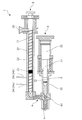
- An injection apparatus 1 shown in FIG. 1 has a plasticizing unit 2 for plasticizing a charged material resin and an injection unit 3 for injecting a plasticized molten resin.
- the heating cylinder 20 provided in the plasticizing unit 2 and the heat retaining cylinder 30 provided in the injection unit 3 are installed in parallel, and the rotary valve 40 is provided inside the both ends. It is connected via the connected connecting part 4.
- a nozzle portion 5 connected to a molding die (not shown) is connected to the front end side of the heat retaining cylinder 30 provided in the injection unit 3 via the connecting portion 4.
- the rotary valve 40 includes a cross head 41 having a T-shaped cross section and a hollow section having a circular cross section around the intersection, and a hollow section formed in the cross head 41. And a valve 42 having a T-shaped passage formed in a rotatable manner. Then, as shown in FIG. 2, the rotary valve 40 is switched to close the nozzle portion 5 side, and the plasticizing unit 2 and the injection unit 3 are connected, so that the molten resin plasticized by the plasticizing unit 2 can be obtained. It can be sent out to the injection unit 3. On the other hand, as shown in FIG. 3, by switching the rotary valve 40 and closing the plasticizing unit 2 side, the injection unit 3 and the nozzle part 5 are connected, so that the molten resin sent to the injection unit 3 is nozzled. It can be injected from the part 5.
- a screw 21 having a spirally formed blade portion 22 is disposed inside the heating cylinder 20 provided in the plasticizing unit 2.
- the rotation, advance / retreat movement of the screw 21 in the heating cylinder 20, and the resin pressure during plasticization are controlled by a screw drive unit, a screw advance mechanism, and a back pressure control unit (not shown).
- a hopper 25 is provided on the rear end side of the heating cylinder 20 for charging the pellet-shaped material resin into the heating cylinder 20.
- the material resin put into the heating cylinder 20 from the hopper 25 is sent to the tip end side of the screw 21 by the screw 21 rotating in the heating cylinder 20 and is sheared and attached to the heating cylinder 20 while being sheared. It is melted and plasticized by the heat from the heater. The material resin thus plasticized is sent to the front end side of the heating cylinder 20 while being kneaded by the rotation of the screw 21.
- the heating cylinder 20 is provided with foaming gas injection valves 24a and 24b for injecting a foaming gas to be impregnated into the plasticized molten resin.
- a foaming gas such as carbon dioxide gas or nitrogen gas can be used.
- the screw 21 is opened in the direction in which the molten resin that has been supplied from the hopper 25 and plasticized is sent to the tip side of the heating cylinder 20, but is not opened in the opposite direction.
- a check valve 23 is provided. Then, the plasticized molten resin that has been sent to the front end side of the heating cylinder 20 by the rotation of the screw 21 and passed through the check valve 23 is impregnated with foaming gas.
- the check valve 23 provided in the screw 21 prevents the foamed gas injected into the heating cylinder 20 from flowing out to the rear end side of the heating cylinder 20, and the molten resin sent to the front end side of the heating cylinder 20 is prevented. By avoiding a decrease in the resin pressure, the foaming gas impregnated in the molten resin is prevented from being foamed by the reduced pressure in the heating cylinder 20.
- the screw 21 moves backward so as to be pushed back by the resin pressure, and the front end side of the heating cylinder 20
- the advancing and retreating movement is controlled so as to move forward when a certain amount of plasticized molten resin is accumulated.
- the back pressure control unit of the plasticizing unit 2 controls the retreat of the screw 21 to keep the resin pressure of the molten resin constant or above a certain level, thereby suppressing foaming of the impregnated inert gas. it can.
- the plasticizing unit 2 is plasticized by accumulating the molten resin impregnated with the foaming gas on the tip side of the heating cylinder 20 and moving the screw 21 retracted to a predetermined position.
- the impregnated molten resin is sent out to the injection unit 3.
- the stroke length by which the screw 21 moves forward and backward can be appropriately set according to the amount of molten resin sent to the injection unit 3, that is, the dimensions of an injection molded body such as a preform and the number of mold cavities.
- the foaming gas injection valve 24 provided in the heating cylinder 20 reaches the position where the screw 21 is most retracted (hereinafter referred to as “retreat limit”), the foaming is performed toward the rear end side with respect to the tip of the screw 21. It can be set according to the stroke length that the screw 21 moves forward and backward so that the gas injection valve 24 is positioned.
- the number of foaming gas injection valves 24 provided in the heating cylinder 20 may be one, but in the example shown in FIG. 1, a plurality (two) of foaming gas injection valves 24 a and 24 b are provided along the forward and backward direction of the screw 21. It is.
- the foaming gas injection valve 24 positioned on the rear end side with respect to the tip of the screw 21 according to the position of the screw 21 moving forward and backward within the heating cylinder 20.
- the foaming gas injection valve 24 is switched so that the foaming gas is injected from 24.
- the injection valve 24 a is positioned on the distal end side with respect to the distal end of the screw 21.
- the injection of the foaming gas from the foaming gas injection valve 24a is stopped, and the foaming gas is injected from the foaming gas injection valve 24b located on the rear end side with respect to the tip of the screw 21.
- the foaming gas injection valve 24 may be switched.
- the position of the check valve 23 provided on the screw 21 is the rear end side of the heating cylinder 20 provided with the foaming gas injection valve 24 even when the screw 21 reaches the most advanced position (hereinafter referred to as “advance limit”).
- Advance limit can be set to be located.
- the foaming gas injection valve 24 may be switched so that the injection of the inert gas from the foaming gas injection valve 24 is stopped.
- the check valve 23 is provided on the screw 21.
- the check valve 23 is formed on the rear end side of the heating cylinder 20 with the molten resin impregnated with the foaming gas injected into the heating cylinder 20.
- the main purpose is to prevent leakage.
- the transfer process is performed by moving the screw 21 forward while rotating, and while the transfer process using the screw 21 is performed, the screw 21 is fed to the front end side of the heating cylinder 20 as the screw rotates. An internal pressure (thrust Pm) of the molten resin is generated. For this reason, by designing and setting the screw 21 so that the thrust Pm is larger than the transfer pressure (Pt), a check valve for preventing the back flow of the material resin is provided at the tip of the screw 21. There is no need.
- the spiral blade portion 22 for plasticizing the material resin can be formed up to the tip of the screw 21. For this reason, the material resin Plasticization and the kneading state of the inert foaming gas and the molten resin can be improved.
- a plunger rod 31 as an injection member is disposed inside the heat retaining cylinder 30 provided in the injection unit 3. Then, the forward / backward movement of the plunger 32 in the heat retaining cylinder 30 is controlled by a plunger drive unit (not shown).
- the material resin is plasticized by the plasticizing unit 2, and the plasticized molten resin is impregnated with the foaming gas, sent to the injection unit 3, and accumulated in the heat retaining cylinder 30 of the injection unit 3.
- the plunger rod 31 is pushed back by the resin pressure of the molten resin accumulated in the heat retaining cylinder 30 and retracted, and at this time, by appropriately adjusting the stroke length of the plunger 32 moving forward and backward, The molten resin to be injected is weighed.
- the plunger 32 moves backward while maintaining the resin pressure of the molten resin accumulated in the heat retaining cylinder 30 at a constant value or above a certain level. 32, the advance / retreat movement of the plunger 32 is controlled so as to move forward when a predetermined amount of molten resin is accumulated in the heat retaining cylinder 30.
- the injection unit 3 moves the plunger 32 backward and forward to measure the molten resin accumulated in the heat retaining cylinder 30, and a predetermined amount of the molten resin is injected from the nozzle unit 5.
- a foamable injection-molded article is manufactured by using the above-described injection apparatus 1 through a plasticizing process, a transfer process, and an injection process described below.
- the pellet-shaped material resin put into the heating cylinder 20 from the hopper 25 is plasticized.
- the foamed gas is impregnated into the plasticized molten resin by injecting the foamed gas from the foamed gas injection valve 24. The timing of injecting the foamed gas will be described later.
- the rotary valve 40 is switched as shown in FIG. 3, and the material resin introduced from the hopper 25 is plasticized as described above. 4 (a) to 4 (c), the screw 21 rotating in the heating cylinder 20 plasticizes the material resin, and the molten resin impregnated with the foaming gas is applied to the front end side of the heating cylinder 20. While feeding, it is pushed back by the resin pressure of the molten resin accumulated on the front end side of the heating cylinder 20 and moves backward.
- FIG. 4A shows a state in which the rotating screw 21 starts to retract in the initial state of the plasticizing process.
- the screw 21 is set up to the set stroke or set. Retreat until time passes.
- FIG. 4D shows a state in which the screw 21 starts moving forward while rotating in the initial state of the transfer process. Then, as shown in FIG. 4E and FIG. 4F in order, the molten resin accumulated on the front end side of the heating cylinder 20 is sent out to the injection unit 3.
- the screw 21 (see FIG. 4 (c)) that has retracted until the set stroke or until the set time has passed is not transferred to the transfer process after the plasticizing process is completed.
- the rotation is stopped, the resin pressure of the molten resin accumulated on the front end side of the heating cylinder 20 is kept constant or above a certain level, and the rotation of the screw 21 is resumed and advanced after a predetermined time.
- the resin pressure of the molten resin accumulated on the tip side of the heating cylinder 20 is kept constant or constant, and the screw 21 moves backward until the set stroke or until the set time elapses.
- the screw 21 may be advanced without stopping the rotation of the screw 21 by shifting to the transfer step. Then, while the rotation of the screw 21 is controlled, the screw 21 is moved back to the transfer process after the screw 21 is moved back to a predetermined position, thereby accumulating on the front end side of the heating cylinder 20 at the final stage of the plasticizing process.
- the resin pressure of the molten resin thus obtained can be kept constant until the transfer process is started.
- the molten resin sent to the injection unit 3 is accumulated in the heat retaining cylinder 30 while the plunger rod 31 is pushed back by the resin pressure and retracted (see FIGS. 4E and 4F). A predetermined amount is measured according to the stroke length of the rod 31.
- the rotary valve 40 is switched as shown in FIG.
- the plasticizing process shown in order in FIG. The timing at which the plasticizing process is restarted by switching the rotary valve 40 may be the same as the time when the screw 21 reaches the forward limit, or after being rotated for a while at the forward limit of the screw, or before the screw 21 reaches the forward limit.
- the screw 21 is kept rotating in order to prevent decompression of the molten resin from the tip of the screw 21 at the connecting portion.
- FIG. 4A shows a state in which the plunger 32 starts to advance in the initial state of the injection process. Then, as shown in order in FIG. 4B and FIG.
- the foamable injection-molded article is manufactured by repeating the above-described steps.
- the timing for injecting the foaming gas into the molten resin kneaded and plasticized by the rotating screw 21 is as follows. Can be controlled.
- the foaming gas injection is started simultaneously with the start of the transfer process or after a certain time has elapsed since the transfer process was started.
- the injection of the foaming gas is started after the screw 21 moving forward in the heating cylinder 20 reaches a predetermined position.
- the injection of foaming gas is started after a certain time has elapsed since the plasticization process was started.
- the plasticizing step is started, and then the injection of the foaming gas is started after the screw 21 moving forward in the heating cylinder 20 reaches a predetermined position.
- the optimum timing for injecting the foaming gas is selected from the above (1) to (4).
- an optimal injection start time can be selected from the above (1) or (2) in consideration of the relationship with other conditions.
- the injection start time can be selected from said (3) or (4).
- the parameters such as the injection pressure and the injection amount of the foaming gas are set and controlled in advance as appropriate in consideration of the optimization of the injection molded product.
- FIG. 5 shows an example of the start timing (1), (2), (3), and (4) of foaming gas injection into the plasticized molten resin described above.
- FIG. I shows shown as a double line, and the portion without the double line stops injection.
- the moving amount of the position of the screw 21 is indicated by a solid line
- the retreat limit where the screw 21 is most retracted and plasticization is completed is indicated by Lba
- the advance limit where the screw 21 is most advanced is indicated by Lad.
- a change in the resin pressure of the molten resin accumulated on the tip side of the heating cylinder 20 is indicated by a one-dot chain line.
- the foaming gas injection start timing and the injection period in this manner, the foaming gas can be injected into the molten resin that has been kneaded by the rotating screw 21. Then, when shifting from the transfer process to the plasticizing process, the screw 21 that has advanced to the forward limit or in front of it in the transfer process starts to retreat while rotating, but stops the injection of the foaming gas before the plasticizing process ends. To do. In other words, a necessary amount of foaming gas is injected between the start of injection (1) to (4) and the end of the plasticizing step.
- the foaming gas injection start timing for the plasticized molten resin to (1) and (2) described above, the foaming gas can be injected immediately after the transfer starts, that is, immediately after the screw rotation starts.
- a large proportion of the gas injection time can be secured in the time from the start of rotation to the stop of screw rotation.
- the amount of gas injection can be increased, and the gas can be uniformly and uniformly injected during the plasticizing process.
- the foaming gas injection start timing to (3) and (4) described above, the resin pressure is relatively stable because the gas is injected at the timing when the screw is monotonously retracted after the transfer is completed.
- the gas injection amount can be easily controlled with high accuracy.
- the resin pressure Pm of the molten resin before passing through the check valve 23 is set to the injection pressure P2 of the foaming gas and the check valve 23.
- These pressures are appropriately adjusted so as to be larger than the sum of the transfer pressure P3 of the molten resin sent to the front end side of the heating cylinder 20 through (Pm> P2 + P3).
- the total pressure of p2 + p3 is detected by the resin pressure sensor S mounted on the same circumference as the mounting position of the foaming gas injection valve 24, and a predetermined resin pressure is determined.
- a predetermined resin pressure is determined.
- (A) The material resin is plasticized by the screw 21 in the heating cylinder 20 of the plasticizing unit 2, and the plasticized molten resin is impregnated with the foaming gas injected from the foaming gas injection valve 24 and rotates.
- an inert gas such as carbon dioxide or nitrogen gas is foamed into a thermoplastic resin such as polyethylene terephthalate by applying the present invention.
- a thermoplastic resin such as polyethylene terephthalate
- the present invention has been described with reference to the preferred embodiments. However, the present invention is not limited to the above-described embodiments. For example, as described above, foaming of an inert gas or the like on a thermoplastic resin. It can also be applied to the manufacturing technology of foamable injection-molded bodies that form fine bubbles during injection molding of injection molded bodies such as preforms, and various modifications can be made within the scope of the present invention. It goes without saying that there is.
- the present invention is not limited to such a technical field, and can be applied in various technical fields as a manufacturing technique for a foamable injection-molded article impregnated with a foaming gas such as an inert gas.
- the present invention can be applied in various technical fields as a technique for producing a foamable injection-molded article impregnated with a foaming gas such as an inert gas.
Landscapes
- Engineering & Computer Science (AREA)
- Manufacturing & Machinery (AREA)
- Mechanical Engineering (AREA)
- Injection Moulding Of Plastics Or The Like (AREA)
- Molding Of Porous Articles (AREA)
Abstract
可塑化され、発泡ガスが含浸された溶融樹脂が、加熱シリンダ20内で回転するスクリュー21によって加熱シリンダ20の先端側に送られて、加熱シリンダ20の先端側への当該溶融樹脂の蓄積に伴ってスクリュー21が後退する可塑化工程と、スクリュー21が回転しながら前進して、加熱シリンダ20の先端側に蓄積された当該溶融樹脂を可塑化ユニット2から射出ユニット3に送り出すトランスファー工程と、射出ユニット3から溶融樹脂を射出する射出工程を行い、これらの工程を繰り返して発泡性射出成形体を製造する。これによって、発泡ガスを含浸させた発泡性射出成形体の射出成形に際し、成形サイクル中の材料樹脂の可塑化、及び可塑化された溶融樹脂への発泡ガスの含浸の向上を図り、生産性を向上させることができる。
Description
本発明は、熱可塑性樹脂に不活性ガス等の発泡ガスを含浸させて射出成形したプリフォーム等の発泡性射出成形体の製造方法及びそのような発泡性射出成形体を製造するための射出装置に関する。
従来、ポリエチレンテレフタレートなどの熱可塑性樹脂を用いて、射出成形体である有底筒状のプリフォームを射出成形し、次いで、このプリフォームを二軸延伸ブロー成形などによって成形してなる合成樹脂製ボトルが、各種飲料等の内容物を充填する容器として広い分野で一般的に利用されている。
また、このような合成樹脂製ボトルにあっては、光によって変質し易い内容物を充填することができるように、前記熱可塑性樹脂に顔料などの着色剤を配合して遮光性を付与することも知られている。
また、このような合成樹脂製ボトルにあっては、光によって変質し易い内容物を充填することができるように、前記熱可塑性樹脂に顔料などの着色剤を配合して遮光性を付与することも知られている。
しかしながら、近年にあっては、使用済みのボトルを回収して、リサイクル樹脂として種々の用途への再利用が図られているところ、着色剤が配合されていると再利用できる用途が限られてしまうという問題があった。このため、着色剤を配合せず、ボトル壁に発泡を分布させることによって遮光性を付与する技術として、熱可塑性樹脂に不活性ガス等の発泡ガスを含浸させ、プリフォームの射出成形時に微細な気泡を形成させ、次いで、このプリフォームを二軸延伸ブロー成形の加熱・ブロー工程によって発泡させて、所定のボトル形状に成形する技術が提案されている。
これに対し、本出願人の一人は、より遮光性を向上させ、気泡による外観の低下を抑制する技術を先に提案した(特許文献1参照)。
かかる技術は、不活性ガス等の発泡ガスを樹脂に含浸させ、プリフォームの射出成形時に気泡の形成を抑制して非発泡状態のプリフォームとし、次いで、このプリフォームを二軸延伸ブロー成形時の加熱・ブロー工程によって発泡させて、小さく、且つ多くの気泡を分布させた所定のボトル形状に成形するというものである。
これに対し、本出願人の一人は、より遮光性を向上させ、気泡による外観の低下を抑制する技術を先に提案した(特許文献1参照)。
かかる技術は、不活性ガス等の発泡ガスを樹脂に含浸させ、プリフォームの射出成形時に気泡の形成を抑制して非発泡状態のプリフォームとし、次いで、このプリフォームを二軸延伸ブロー成形時の加熱・ブロー工程によって発泡させて、小さく、且つ多くの気泡を分布させた所定のボトル形状に成形するというものである。
一方、前述した発泡性射出成形体の射出成形方法として、押出ユニットと射出ユニットから成る2ステージ・プリプラ式の射出装置を利用した技術が提案されている(特許文献2参照)。かかる技術は、押出ユニットで不活性ガス等の発泡ガスを含浸させた溶融樹脂を、射出ユニットに設けられた往復動するプランジャーを用いて射出金型に注入するものであり、前記注入前に導管を介して溶融樹脂を蓄積するアキュムレーターを備えている。
そして、前述した特許文献1等の合成樹脂製発泡ボトルを量産する際に、成形サイクルが早く、使用樹脂量が多いプリフォーム等の射出成形体の製造に際しては、前記特許文献2に示される2ステージ・プリプラ式の射出装置を利用した技術の採用が考えられる。
しかしながら、不活性ガス等の発泡ガスを含浸させたプリフォーム等の発泡性射出成形体の射出成形おいては、発泡ガスを可塑化工程で、即ち、樹脂溶融工程で均一に含浸させる必要があり、通常の射出成形より高い溶融樹脂圧の設定が必要になるとともに、可塑化時間が長くなる。このため、成形サイクル中の押出ユニットのスクリュー回転、及びガスの注入時間を増加させて、可塑化能力とガスの含浸の向上を図り、生産性を向上させることが望まれる。
しかしながら、不活性ガス等の発泡ガスを含浸させたプリフォーム等の発泡性射出成形体の射出成形おいては、発泡ガスを可塑化工程で、即ち、樹脂溶融工程で均一に含浸させる必要があり、通常の射出成形より高い溶融樹脂圧の設定が必要になるとともに、可塑化時間が長くなる。このため、成形サイクル中の押出ユニットのスクリュー回転、及びガスの注入時間を増加させて、可塑化能力とガスの含浸の向上を図り、生産性を向上させることが望まれる。
そこで、本発明者らは、プリフォーム等の射出成形体に不活性ガス等の発泡ガスを含浸させた発泡性射出成形体の2ステージ・プリプラ式の射出成形に際し、成形サイクル中の材料樹脂の可塑化時間、及びガスの注入時間を増加させ、可塑化能力とガスの含浸の向上を図るという観点から鋭意検討した結果、本発明を完成するに至った。
すなわち、本発明は、プリフォーム等の発泡性射出成形体の射出成形に際し、成形サイクル中の材料樹脂の可塑化時間、及び可塑化された溶融樹脂への発泡ガスの注入時間を増加させ、材料樹脂の可塑化と溶融樹脂への発泡ガスの含浸の向上を図ることができる発泡性射出成形体の製造方法及びそのような発泡性射出成形体を製造するための射出装置の提供を目的とする。
本発明に係る発泡性射出成形体の製造方法は、材料樹脂を可塑化する可塑化ユニットと、可塑化された溶融樹脂を射出する射出ユニットとを有し、前記可塑化ユニットが、発泡ガス注入バルブが設けられた加熱シリンダと、前記加熱シリンダの内部に配設されたスクリューとを備える射出装置を用いた発泡性射出成形体の製造方法において、前記材料樹脂が、前記可塑化ユニットの加熱シリンダ内のスクリューで可塑化されるとともに、可塑化された溶融樹脂に前記発泡ガス注入バルブから注入される発泡ガスが含浸され、回転する前記スクリューによる前記溶融樹脂の前記加熱シリンダの先端側への蓄積に伴って前記スクリューが後退する可塑化工程と、所定の位置まで後退した前記スクリューを回転させながら前進させ、前記加熱シリンダの先端側に蓄積された前記溶融樹脂を、前記射出ユニットに送り出すトランスファー工程とを行い、前記トランスファー工程が終了すると、前記スクリューの回転を停止することなく前記可塑化工程を再開するとともに、前記射出ユニットから前記溶融樹脂を射出する射出工程を行い、前記射出工程が終了すると、前記可塑化工程を終了するとともに、前記トランスファー工程を再開する方法としてある。
また、本発明に係る射出装置は、材料樹脂を可塑化する可塑化ユニットと、可塑化された溶融樹脂を射出する射出ユニットとを有する射出装置であって、前記可塑化ユニットが、発泡ガス注入バルブが設けられた加熱シリンダと、前記加熱シリンダの内部に配設されたスクリューとを備え、前記材料樹脂が、前記可塑化ユニットの加熱シリンダ内のスクリューで可塑化されるとともに、可塑化された溶融樹脂に前記発泡ガス注入バルブから注入される発泡ガスが含浸され、回転する前記スクリューによる前記溶融樹脂の前記加熱シリンダの先端側への蓄積に伴って前記スクリューが所定の位置まで後退した後に、前記スクリューが回転しながら前進して、前記加熱シリンダの先端側に蓄積された前記溶融樹脂を前記射出ユニットに送り出すように、前記スクリューの回転及び進退移動が制御されている構成としてある。
本発明によれば、発泡ガスを含浸させた熱可塑性樹脂を射出成形して発泡性射出成形体を製造するにあたり、成形サイクル中の材料樹脂の可塑化時間、及び可塑化された溶融樹脂への発泡ガスの注入時間を増加させ、可塑化能力と発泡ガスの含浸の向上を図り、生産性を向上させることができる。
以下、本発明の好ましい実施形態について、図面を参照しつつ説明する。
[射出装置]
図1に示す射出装置1は、投入された材料樹脂を可塑化するための可塑化ユニット2と、可塑化された溶融樹脂を射出するための射出ユニット3とを有している。
図1に示す射出装置1は、投入された材料樹脂を可塑化するための可塑化ユニット2と、可塑化された溶融樹脂を射出するための射出ユニット3とを有している。
図1に示す射出装置1において、可塑化ユニット2が備える加熱シリンダ20と、射出ユニット3が備える保温シリンダ30とは並列して設置されており、両者の先端側が、ロータリーバルブ40が内部に設けられた連結部4を介して連結されている。これとともに、射出ユニット3が備える保温シリンダ30の先端側には、当該連結部4を介して、図示しない成形型に接続されるノズル部5が連結されている。
ロータリーバルブ40は、図2及び図3に示すように、断面T字型の通路及びその交差点を中心に断面円形の中空部が形成されたクロスヘッド41と、クロスヘッド41に形成された中空部内に回動可能に取り付けられ、かつ、断面T字型の通路が形成されたバルブ42とを備えている。
そして、図2に示すようにロータリーバルブ40を切り換えて、ノズル部5側を閉じるとともに、可塑化ユニット2と射出ユニット3とを接続することにより、可塑化ユニット2で可塑化された溶融樹脂を射出ユニット3に送り出すことができるようになっている。一方、図3に示すようにロータリーバルブ40を切り換えて、可塑化ユニット2側を閉じるとともに、射出ユニット3とノズル部5とを接続することにより、射出ユニット3に送られてきた溶融樹脂をノズル部5から射出できるようになっている。
そして、図2に示すようにロータリーバルブ40を切り換えて、ノズル部5側を閉じるとともに、可塑化ユニット2と射出ユニット3とを接続することにより、可塑化ユニット2で可塑化された溶融樹脂を射出ユニット3に送り出すことができるようになっている。一方、図3に示すようにロータリーバルブ40を切り換えて、可塑化ユニット2側を閉じるとともに、射出ユニット3とノズル部5とを接続することにより、射出ユニット3に送られてきた溶融樹脂をノズル部5から射出できるようになっている。
可塑化ユニット2が備える加熱シリンダ20の内部には、螺旋状に形成された羽根部22を有するスクリュー21が配設されている。そして、図示しないスクリュー駆動部、スクリュー前進機構、及び背圧制御部によって、加熱シリンダ20内でのスクリュー21の回転、進退移動、及び可塑化時の樹脂圧が制御されるようになっている。
また、加熱シリンダ20の後端側には、ペレット状の材料樹脂を加熱シリンダ20内に投入するためのホッパー25が設けられている。
ホッパー25から加熱シリンダ20内に投入された材料樹脂は、加熱シリンダ20内で回転するスクリュー21によってスクリュー21の先端側に送られるとともに、せん断されつつ、せん断熱と、加熱シリンダ20に取り付けられたヒーターからの熱によって溶融し、可塑化される。このようにして可塑化される材料樹脂は、スクリュー21の回転によって混錬されながら、加熱シリンダ20先端側に送られる。
ホッパー25から加熱シリンダ20内に投入された材料樹脂は、加熱シリンダ20内で回転するスクリュー21によってスクリュー21の先端側に送られるとともに、せん断されつつ、せん断熱と、加熱シリンダ20に取り付けられたヒーターからの熱によって溶融し、可塑化される。このようにして可塑化される材料樹脂は、スクリュー21の回転によって混錬されながら、加熱シリンダ20先端側に送られる。
また、加熱シリンダ20には、可塑化された溶融樹脂に含浸させる発泡ガスを注入するための発泡ガス注入バルブ24a,24bが設けられている。発泡ガスとしては、炭酸ガス又は窒素ガス等の不活性ガスを利用することができる。
これとともに、スクリュー21には、ホッパー25から投入されて可塑化された溶融樹脂が加熱シリンダ20の先端側に送られていく方向には開くが、その逆の方向には開かないようにされた逆止弁23が設けられている。そして、スクリュー21の回転によって加熱シリンダ20の先端側に送られて、逆止弁23を通過してきた可塑化された溶融樹脂に、発泡ガスを含浸させる。
そして、スクリュー21に設けた逆止弁23により、加熱シリンダ20内に注入された発泡ガスの加熱シリンダ20の後端側への流出を防止し、加熱シリンダ20の先端側に送られる溶融樹脂の樹脂圧の低下を回避して、当該溶融樹脂に含浸された発泡ガスの加熱シリンダ20内の減圧による発泡を抑止している。
また、スクリュー21は、可塑化され、不活性ガスが含浸された溶融樹脂の加熱シリンダ20の先端側への蓄積に伴って、その樹脂圧によって押し戻されるように後退し、加熱シリンダ20の先端側に一定量の可塑化した溶融樹脂が蓄積されると前進するように、その進退移動が制御されている。この際、可塑化ユニット2の背圧制御部でスクリュー21の後退を制御して当該溶融樹脂の樹脂圧を一定或いは一定以上に保つことで、含浸された不活性ガスの発泡を抑止することができる。
このように、可塑化ユニット2は、加熱シリンダ20の先端側に発泡ガスが含浸された溶融樹脂が蓄積され、所定の位置まで後退したスクリュー21を前進させることによって、可塑化され、発泡ガスが含浸された溶融樹脂を、射出ユニット3に送り出す。このとき、スクリュー21が進退移動するストローク長は、射出ユニット3に送り出す溶融樹脂の量、すなわち、プリフォーム等の射出成形体の寸法、成形型キャビティー数に応じて適宜設定することができる。
ここで、加熱シリンダ20に設ける発泡ガス注入バルブ24の位置は、スクリュー21が最も後退した位置(以下、「後退限」という)に達しても、スクリュー21の先端に対して後端側に発泡ガス注入バルブ24が位置するように、スクリュー21が進退移動するストローク長に応じて設定することができる。加熱シリンダ20に設ける発泡ガス注入バルブ24は一つであってもよいが、図1に示す例では、複数(二つ)の発泡ガス注入バルブ24a,24bをスクリュー21の進退方向に沿って設けてある。このように、複数の発泡ガス注入バルブ24を設ける場合には、加熱シリンダ20内で進退移動するスクリュー21の位置に応じて、スクリュー21の先端に対して後端側に位置する発泡ガス注入バルブ24から発泡ガスの注入がなされるように、発泡ガス注入バルブ24を切り換える。
例えば、図4(a)及び図4(b)に示す例では、スクリュー21が後退する過程で、二つの発泡ガス注入バルブ24a,24bのうち、加熱シリンダ20の先端側に設けられた発泡ガス注入バルブ24aは、スクリュー21の先端に対して先端側に位置するようになる。このような場合には、発泡ガス注入バルブ24aからの発泡ガスの注入を停止し、スクリュー21の先端に対して後端側に位置する発泡ガス注入バルブ24bから発泡ガスが注入されるように、発泡ガス注入バルブ24を切り換えるとよい。
一方、スクリュー21に設ける逆止弁23の位置は、スクリュー21が最も前進した位置(以下、「前進限」という)に達しても、発泡ガス注入バルブ24を設けた加熱シリンダ20の後端側に位置するように設定することができる。また、複数の逆止弁23を設けるときには、発泡ガス注入バルブ24を設けた加熱シリンダ20の先端側に位置させる場合もある。そのような場合には、当該発泡ガス注入バルブ24から不活性ガスの注入が停止されるように、発泡ガス注入バルブ24を切り換えるようにすればよい。
なお、本実施形態ではスクリュー21に逆止弁23を設けるが、この逆止弁23は、加熱シリンダ20内に注入された発泡ガスが含浸された溶融樹脂が、加熱シリンダ20の後端側に流出しないようにすることを主目的として設けられるものである。本実施形態にあっては、スクリュー21を回転させながら前進させることによってトランスファー工程を行っており、スクリュー21によるトランスファー工程が行われている間は、スクリュー回転に伴う加熱シリンダ20の先端側に送られる溶融樹脂の内部圧力(推力Pm)が発生する。このため、推力Pmがトランスファー圧力(Pt)よりも大きくなるようにスクリュー21の設計、条件設定を行うことにより、スクリュー21の先端部には、材料樹脂の逆流を防止する逆止弁などを設ける必要がなくなる。
本発明のスクリュー21の先端部には、前述したように逆止弁を設けないため、材料樹脂を可塑化する螺旋状の羽根部22をスクリュー21の先端部まで形成でき、このため、材料樹脂の可塑化や不活性発泡ガスと溶融樹脂との混練状態を向上させることができる。
本発明のスクリュー21の先端部には、前述したように逆止弁を設けないため、材料樹脂を可塑化する螺旋状の羽根部22をスクリュー21の先端部まで形成でき、このため、材料樹脂の可塑化や不活性発泡ガスと溶融樹脂との混練状態を向上させることができる。
また、射出ユニット3が備える保温シリンダ30の内部には、射出部材としてのプランジャーロッド31が配設されている。そして、図示しないプランジャー駆動部によって、保温シリンダ30内のプランジャー32の進退移動が制御されるようになっている。
そして、材料樹脂は、可塑化ユニット2で可塑化されるとともに、可塑化された溶融樹脂に発泡ガスが含浸されて射出ユニット3に送られ、射出ユニット3の保温シリンダ30内に蓄積される。これに伴い、保温シリンダ30内に蓄積された当該溶融樹脂の樹脂圧によって、プランジャーロッド31が押し戻されて後退し、このとき、プランジャー32の進退移動するストローク長を適宜調整することで、射出される溶融樹脂の計量が行われる。また、溶融樹脂に含浸された発泡ガスの発泡を抑止するため、プランジャー32は、保温シリンダ30内に蓄積される溶融樹脂の樹脂圧を一定或いは一定以上に保ちながら後退し、一方、プランジャー32は、保温シリンダ30内に所定量の溶融樹脂が蓄積されると前進するように、プランジャー32の進退移動が制御されている。
このように、射出ユニット3は、プランジャー32を後退、前進させることによって、保温シリンダ30に蓄積された溶融樹脂が計量され、所定量の溶融樹脂がノズル部5から射出される。
本実施形態では、前述した射出装置1を用いて、次に説明する可塑化工程、トランスファー工程、射出工程を経ることによって、発泡性射出成形体を製造する。
[可塑化工程]
まず、可塑化ユニット2において、ホッパー25から加熱シリンダ20内に投入されたペレット状の材料樹脂を可塑化する。
なお、本実施形態では、発泡ガス注入バルブ24から発泡ガスを注入することによって、可塑化された溶融樹脂に発泡ガスを含浸させるが、発泡ガスを注入する時期については後述する。
まず、可塑化ユニット2において、ホッパー25から加熱シリンダ20内に投入されたペレット状の材料樹脂を可塑化する。
なお、本実施形態では、発泡ガス注入バルブ24から発泡ガスを注入することによって、可塑化された溶融樹脂に発泡ガスを含浸させるが、発泡ガスを注入する時期については後述する。
この可塑化工程では、ロータリーバルブ40が図3に示すように切り換えられており、ホッパー25から投入された材料樹脂が、前述したようにして可塑化される。そして、図4(a)~(c)に順に示すように、加熱シリンダ20内で回転するスクリュー21が、材料樹脂を可塑化し、発泡ガスが含浸された溶融樹脂を加熱シリンダ20の先端側に送りつつ、加熱シリンダ20の先端側に蓄積された溶融樹脂の樹脂圧によって押し戻されて後退する。
ここで、図4(a)は、可塑化工程の初期の状態において、回転するスクリュー21が後退し始めた状態を示している。そして、図4(b)及び図4(c)に順に示すように、加熱シリンダ20の先端側に溶融樹脂が蓄積されていくに伴って、スクリュー21が設定されたストロークまで、或いは設定された時間が経過するまで後退する。
ここで、図4(a)は、可塑化工程の初期の状態において、回転するスクリュー21が後退し始めた状態を示している。そして、図4(b)及び図4(c)に順に示すように、加熱シリンダ20の先端側に溶融樹脂が蓄積されていくに伴って、スクリュー21が設定されたストロークまで、或いは設定された時間が経過するまで後退する。
[トランスファー工程]
可塑化工程に続いて行われるトランスファー工程では、可塑化ユニット2で可塑化され、発泡ガスが含浸された溶融樹脂を射出ユニット3に送り出すが、これに先立って、ロータリーバルブ40を図2に示すように切り換える。そして、可塑化工程において後退したスクリュー21の先端側に、所定量の溶融樹脂が蓄積されると、図4(d)~(e)に順に示すように、スクリュー21を回転させながら前進させる。スクリュー21は、その後、必要に応じて前進限で回転を続けてもよい。これにより、可塑化され、発泡ガスが含浸された所定量の溶融樹脂が射出ユニット3に送り出される。
ここで、図4(d)は、トランスファー工程の初期の状態において、スクリュー21が回転しながら前進し始めた状態を示している。そして、図4(e)及び図4(f)に順に示すように、加熱シリンダ20の先端側に蓄積された溶融樹脂が射出ユニット3に送り出される。
このとき、可塑化工程において、設定されたストロークまで、或いは設定された時間が経過するまで後退したスクリュー21(図4(c)参照)は、可塑化工程の完了後、トランスファー工程に移行する前にサイクルによっては回転を停止し、加熱シリンダ20の先端側に蓄積された溶融樹脂の樹脂圧を一定或いは一定以上に保ち、所定時間経過後にスクリュー21の回転を再開するとともに前進させる。可塑化工程の終期において、加熱シリンダ20の先端側に蓄積された溶融樹脂の樹脂圧を一定或いは一定に保ち、スクリュー21が設定されたストロークまで、或いは設定された時間が経過するまで後退するのと同時に、トランスファー工程に移行するようにして、スクリュー21の回転を停止することなくスクリュー21を前進させるようにしてもよい。
そして、スクリュー21の回転を制御しつつ、スクリュー21が所定の位置まで後退した後に、スクリュー21を前進させてトランスファー工程に移行することで、可塑化工程の終期における加熱シリンダ20の先端側に蓄積された溶融樹脂の樹脂圧が、トランスファー工程に移行するまでの間に一定に保つことができる。
そして、スクリュー21の回転を制御しつつ、スクリュー21が所定の位置まで後退した後に、スクリュー21を前進させてトランスファー工程に移行することで、可塑化工程の終期における加熱シリンダ20の先端側に蓄積された溶融樹脂の樹脂圧が、トランスファー工程に移行するまでの間に一定に保つことができる。
射出ユニット3に送られてきた溶融樹脂は、その樹脂圧によってプランジャーロッド31を押し戻して後退させながら保温シリンダ30内に蓄積され(図4(e)及び図4(f)参照)、プランジャーロッド31のストローク長に応じて所定量に計量される。そして、プランジャー32が所定の位置まで後退して、トランスファー工程が終了すると(図4(f)参照)、ロータリーバルブ40が図3に示すように切り換えられて、前述した図4(a)~図4(c)に順に示す可塑化工程が再開される。
ロータリーバルブ40の切り換えによって可塑化工程を再開するタイミングは、スクリュー21が前進限に達するのと同時、或いはスクリュー前進限でしばらく回転した後でもよく、また、スクリュー21が前進限に達する手前でもよいが、トランスファー工程から可塑化工程に移行する際には、スクリュー21の先端部から連結部での溶融樹脂の減圧を防ぐ為、スクリュー21は回転したままとする。
このようにスクリュー21を回転したままとすることにより、可塑化能力が向上し、スクリュー内の溶融樹脂圧が安定する。
ロータリーバルブ40の切り換えによって可塑化工程を再開するタイミングは、スクリュー21が前進限に達するのと同時、或いはスクリュー前進限でしばらく回転した後でもよく、また、スクリュー21が前進限に達する手前でもよいが、トランスファー工程から可塑化工程に移行する際には、スクリュー21の先端部から連結部での溶融樹脂の減圧を防ぐ為、スクリュー21は回転したままとする。
このようにスクリュー21を回転したままとすることにより、可塑化能力が向上し、スクリュー内の溶融樹脂圧が安定する。
[射出工程]
トランスファー工程が終了してロータリーバルブ40が図3に示すように切り換えられると、再開された可塑化工程と平行して射出工程が行われる。
射出工程では、図4(a)~(c)に順に示すように、射出ユニット3のプランジャーロッド31が前進することによって、計量された所定量の溶融樹脂がノズル部5から射出され、図示しない成形型によって所定形状の発泡性射出成形体が成形される。
ここで、図4(a)は、射出工程の初期の状態において、プランジャー32が前進し始めた状態を示している。そして、図4(b)及び図4(c)に順に示すように、保温シリンダ30内で計量された所定量の溶融樹脂がノズル5から射出される。
射出工程が終了すると、可塑化工程も終了するとともに(図4(c)参照)、トランスファー工程が再開され(図4(d)参照)、これらの工程が繰り返される。
[不活性ガスの注入時期]
本実施形態では、以上のような工程を繰り繰り返して発泡性射出成形体が製造されるが、回転するスクリュー21によって混錬され、可塑化された溶融樹脂に対する発泡ガスの注入開示時期を次のように制御することができる。
本実施形態では、以上のような工程を繰り繰り返して発泡性射出成形体が製造されるが、回転するスクリュー21によって混錬され、可塑化された溶融樹脂に対する発泡ガスの注入開示時期を次のように制御することができる。
(1)トランスファー工程の開始と同時に、又はトランスファー工程が開始されてから一定の時間が経過した後に、発泡ガスの注入を開始する。
(2)トランスファー工程が開始されてから、加熱シリンダ20内を前進するスクリュー21が所定の位置に達した後に、発泡ガスの注入を開始する。
(3)トランスファー工程終了後、可塑化工程が開始されてから一定の時間が経過した後に、発泡ガスの注入を開始する。
(4)トランスファー工程終了後、可塑化工程が開始されてから、加熱シリンダ20内を前進するスクリュー21が所定の位置に達した後に、発泡ガスの注入を開始する。
(2)トランスファー工程が開始されてから、加熱シリンダ20内を前進するスクリュー21が所定の位置に達した後に、発泡ガスの注入を開始する。
(3)トランスファー工程終了後、可塑化工程が開始されてから一定の時間が経過した後に、発泡ガスの注入を開始する。
(4)トランスファー工程終了後、可塑化工程が開始されてから、加熱シリンダ20内を前進するスクリュー21が所定の位置に達した後に、発泡ガスの注入を開始する。
また、発泡ガスの注入開始時期は、前記(1)~(4)のうち最適な時期を適宜選択する。例えば、発泡ガスの注入時間を長くする場合は、前記(1)又は(2)から、他の諸条件との関係を考慮して最適な注入開始時期を選択することができる。また、発泡ガスの注入時間を短くする場合は、前記(3)又は(4)から注入開始時期を選択することができる。
尚、発泡ガスの注入圧力、注入量等のパラメーターは、射出成形品の最適化を考慮して、適宜、事前に設定、制御される。
尚、発泡ガスの注入圧力、注入量等のパラメーターは、射出成形品の最適化を考慮して、適宜、事前に設定、制御される。
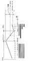
前記(1)~(4)に従って発泡ガスの注入開始時期を制御した場合の、その注入期間、スクリュー21の位置、スクリュー21の回転速度、及び加熱シリンダ20の先端側に蓄積された溶融樹脂の樹脂圧との関係を図5に示す。
そして、前述した可塑化された溶融樹脂に対する発泡ガスの注入開始時期(1)、(2)、(3)、(4)の一例を図5に示すが、図5において、発泡ガスの注入期間は二重線で示され、二重線の無い部分は注入を停止している。
また、スクリュー21の位置の移動量を実線で示し、スクリュー21が最も後退して可塑化が完了した後退限をLba、スクリュー21が最も前進した前進限をLadで示している。さらに、加熱シリンダ20の先端側に蓄積された溶融樹脂の樹脂圧の変化を一点鎖線で示している。
そして、前述した可塑化された溶融樹脂に対する発泡ガスの注入開始時期(1)、(2)、(3)、(4)の一例を図5に示すが、図5において、発泡ガスの注入期間は二重線で示され、二重線の無い部分は注入を停止している。
また、スクリュー21の位置の移動量を実線で示し、スクリュー21が最も後退して可塑化が完了した後退限をLba、スクリュー21が最も前進した前進限をLadで示している。さらに、加熱シリンダ20の先端側に蓄積された溶融樹脂の樹脂圧の変化を一点鎖線で示している。
このようにして発泡ガスの注入開始時期、注入期間を制御することで、回転するスクリュー21によって混錬されている状態にある溶融樹脂に対して発泡ガスを注入することができる。そして、トランスファー工程から可塑化工程に移行する際に、トランスファー工程において前進限又はその手前まで前進したスクリュー21は、回転したまま後退し始めるが、可塑化工程の終了前に発泡ガスの注入を停止する。換言すれば、前記(1)~(4)の注入開始時期から可塑化工程が終了するまでの間に、必要量の発泡ガスが注入される。
従って、発泡ガスの注入を停止した後も、回転するスクリュー21によって発泡ガスが含浸された溶融樹脂の混錬が継続されて、溶融樹脂内の発泡ガスの含浸の均一化が行われる。そして、この結果、成形サイクル中の材料樹脂の可塑化時間を損なうことなく、可塑化された溶融樹脂への必要ガス量の注入が可能となり、可塑化能力と発泡ガスの含浸の向上を図られ、生産性を向上させることができる。
従って、発泡ガスの注入を停止した後も、回転するスクリュー21によって発泡ガスが含浸された溶融樹脂の混錬が継続されて、溶融樹脂内の発泡ガスの含浸の均一化が行われる。そして、この結果、成形サイクル中の材料樹脂の可塑化時間を損なうことなく、可塑化された溶融樹脂への必要ガス量の注入が可能となり、可塑化能力と発泡ガスの含浸の向上を図られ、生産性を向上させることができる。
そして、可塑化された溶融樹脂に対する発泡ガスの注入開始時期を前述した(1)、(2)とすることにより、トランスファー開始後、すなわちスクリュー回転開始直後から発泡ガスを注入することができ、スクリュー回転開始からスクリュー回転停止までの時間の中で、ガス注入時間の割合を多く確保することが可能となる。これにより、ガス注入量を多くすることが可能になり、可塑化工程中に万遍なく均一にガスを注入できる。一方、発泡ガスの注入開始時期を前述した(3)、(4)とすることにより、トランスファーが完了した後、スクリューが単調後退しているタイミングでガスを注入するため樹脂圧力が比較的安定し、ガス注入量を高精度で制御がし易くなる。
また、発泡ガス注入バルブ24から加熱シリンダ20内に発泡ガスを注入する際は、逆止弁23を通過する手前の溶融樹脂の樹脂圧Pmを、発泡ガスの注入圧P2と、逆止弁23を通過して加熱シリンダ20の先端側に送られる溶融樹脂のトランスファー圧力P3との和よりも大きく(Pm>P2+P3)なるように、これらの圧力を適宜調整する。これにより、回転するスクリュー21によって、可塑化された溶融樹脂を加熱シリンダ20の先端側に送る際に、逆止弁23が閉じて、溶融樹脂が逆弁23を通過できないといった不具合を回避することができる。
そして、前述した不具合の回避においては、発泡ガス注入バルブ24の取り付け位置と同じ円周上に取り付けた樹脂圧センサーSでp2+p3の合計の圧力を検知して、当該樹脂圧の予め定められた樹脂圧以上となったときに、発泡ガスの注入圧P2を下げるか、又は射出装置1の動作を制御して停止するのが好ましい。
そして、前述した不具合の回避においては、発泡ガス注入バルブ24の取り付け位置と同じ円周上に取り付けた樹脂圧センサーSでp2+p3の合計の圧力を検知して、当該樹脂圧の予め定められた樹脂圧以上となったときに、発泡ガスの注入圧P2を下げるか、又は射出装置1の動作を制御して停止するのが好ましい。
以上のような実施形態を挙げて説明した本発明にあっては、
(A)材料樹脂が、可塑化ユニット2の加熱シリンダ20内のスクリュー21で可塑化されるとともに、可塑化された溶融樹脂に発泡ガス注入バルブ24から注入される発泡ガスが含浸され、回転するスクリュー21による溶融樹脂の加熱シリンダ20の先端側への蓄積に伴ってスクリュー21が後退する可塑化工程と、
(B)所定の位置まで後退したスクリュー21を回転させながら前進させ、加熱シリンダ20の先端側に蓄積した溶融樹脂を射出ユニット3に送り出すトランスファー工程とを行い、
(C)トランスファー工程が終了すると、スクリュー21の回転を停止することなく可塑化工程を再開するとともに、射出ユニット3から溶融樹脂を射出する射出工程を行い、
(D)射出成形工程が終了し、可塑化工程を終了するとともに、トランスファー工程を再開する、
前記(A)~(D)の工程を繰り返して発泡性射出成形体を製造する。このようにして発泡性射出成形体を製造することにより、特に、トランスファー工程において、加熱シリンダ20の先端側に蓄積され、可塑化及び発泡ガスが含浸された溶融樹脂を射出ユニット3に送り出す際に、スクリュー21を回転させながら前進すること、即ち、材料樹脂の溶融工程を停止することなく継続することで、成形サイクルを低下させないことが可能となる。当該材料樹脂の十分な可塑化および混錬が行われる。さらに、スクリュー21の回転速度と前進速度とを適宜調整することによって、当該発泡ガスが含浸された溶融樹脂に背圧を加えて発泡ガスの発泡を抑止することができる。その結果、材料樹脂の可塑化、発泡ガスの含浸が向上した発泡性射出成形体を製造することができる。
このため、前述したボトル壁に気泡を分布させた合成樹脂製発泡ボトルを量産するにあたり、本発明を適用してポリエチレンテレフタレートなどの熱可塑性樹脂に、炭酸ガス又は窒素ガス等の不活性ガスを発泡ガスとして含浸させてプリフォームを射出成形することで、成形サイクル中の材料樹脂の可塑化、プリフォームへの発泡ガスの含浸を向上させることができる。そして、かかるプリフォームを二軸延伸ブロー成形することにより、ボトル壁に微細な気泡を均一に分布させた合成樹脂製発泡ボトルを歩留りよく量産することができる。
以上、本発明について、好ましい実施形態を示して説明したが、本発明は、前述した実施形態にのみ限定されるものではなく、例えば、前述したように、熱可塑性樹脂に不活性ガス等の発泡ガスを含浸させ、プリフォーム等の射出成形体の射出成形時に、微細な気泡を形成させる発泡性射出成形体の製造技術にも適用可能であり、本発明の範囲で種々の変更実施が可能であることは云うまでもない。
また、本発明が適用される例として、発泡性射出成形体を二軸延伸ブロー成形し、ボトル壁に気泡を分布させた合成樹脂製発泡ボトルを量産する技術を挙げたが、本発明は、そのような技術分野に限らず、不活性ガス等の発泡ガスを含浸させた発泡性射出成形体の製造技術として、種々の技術分野において適用することができる。
以上のように本発明は、不活性ガス等の発泡ガスを含浸させた発泡性射出成形体の製造技術として、種々の技術分野において適用することができる。
1 射出装置
2 可塑化ユニット
20 加熱シリンダ
21 スクリュー
23 逆止弁
24 発泡ガス注入バルブ
3 射出ユニット
2 可塑化ユニット
20 加熱シリンダ
21 スクリュー
23 逆止弁
24 発泡ガス注入バルブ
3 射出ユニット
Claims (13)
- 材料樹脂を可塑化する可塑化ユニットと、可塑化された溶融樹脂を射出する射出ユニットとを有し、前記可塑化ユニットが、発泡ガス注入バルブが設けられた加熱シリンダと、前記加熱シリンダの内部に配設されたスクリューとを備える射出装置を用いた発泡性射出成形体の製造方法において、
前記材料樹脂が、前記可塑化ユニットの加熱シリンダ内のスクリューで可塑化されるとともに、可塑化された溶融樹脂に前記発泡ガス注入バルブから注入される発泡ガスが含浸され、回転する前記スクリューによる前記溶融樹脂の前記加熱シリンダの先端側への蓄積に伴って前記スクリューが後退する可塑化工程と、
所定の位置まで後退した前記スクリューを回転させながら前進させ、前記加熱シリンダの先端側に蓄積された前記溶融樹脂を、前記射出ユニットに送り出すトランスファー工程とを行い、
前記トランスファー工程が終了すると、前記スクリューの回転を停止することなく前記可塑化工程を再開するとともに、前記射出ユニットから前記溶融樹脂を射出する射出工程を行い、
前記射出工程が終了すると、前記可塑化工程を終了するとともに、前記トランスファー工程を再開することを特徴とする発泡性射出成形体の製造方法。 - 前記スクリューを回転させながら前進させた後、さらに前記スクリューを回転させて前記溶融樹脂を前記射出ユニットへ送り出す請求項1に記載の発泡性射出成形体の製造方法。
- 回転する前記スクリューによって可塑化された前記溶融樹脂に対して前記発泡ガスを注入する請求項1又は2に記載の発泡性射出成形体の製造方法。
- 前記トランスファー工程の開始と同時に、又は前記トランスファー工程が開始されてから一定の時間が経過した後に、前記発泡ガスの注入を開始する請求項1乃至3のいずれか一項に記載の発泡性射出成形体の製造方法。
- 前記トランスファー工程が開始されてから、前記加熱シリンダ内を前進する前記スクリューが所定の位置に達した後に、前記発泡ガスの注入を開始する請求項1乃至3のいずれか一項に記載の発泡性射出成形体の製造方法。
- 前記トランスファー工程終了後、前記可塑化工程が開始されてから一定の時間が経過した後に、前記発泡ガスの注入を開始する請求項1乃至3のいずれか一項に記載の発泡性射出成形体の製造方法。
- 前記トランスファー工程終了後、前記可塑化工程が開始されてから前記加熱シリンダ内を前進する前記スクリューが所定の位置に達した後に、前記発泡ガスの注入を開始する請求項1乃至3のいずれか一項に記載の発泡性射出成形体の製造方法。
- 前記可塑化工程の終了前に、前記発泡ガスの注入を停止する請求項1乃至7のいずれか一項に記載の発泡性射出成形体の製造方法。
- 前記スクリューに逆止弁を設け、前記スクリューの回転によって前記加熱シリンダ先端側に送られて、前記逆止弁を通過した前記溶融樹脂に、前記発泡ガスを含浸させる請求項1乃至8のいずれか一項に記載の発泡性射出成形体の製造方法。
- 材料樹脂を可塑化する可塑化ユニットと、可塑化された溶融樹脂を射出する射出ユニットとを有する射出装置であって、
前記可塑化ユニットが、発泡ガス注入バルブが設けられた加熱シリンダと、前記加熱シリンダの内部に配設されたスクリューとを備え、
前記材料樹脂が、前記可塑化ユニットの加熱シリンダ内のスクリューで可塑化されるとともに、可塑化された溶融樹脂に前記発泡ガス注入バルブから注入される発泡ガスが含浸され、回転する前記スクリューによる前記溶融樹脂の前記加熱シリンダの先端側への蓄積に伴って前記スクリューが所定の位置まで後退した後に、
前記スクリューが回転しながら前進して、前記加熱シリンダの先端側に蓄積された前記溶融樹脂を前記射出ユニットに送り出すように、
前記スクリューの回転及び進退移動が制御されていることを特徴とする射出装置。 - 前記加熱シリンダに設けられた前記発泡ガス注入バルブを、
前記スクリューの先端に対して後端側に位置する前記発泡ガス注入バルブから前記発泡ガスの注入がなされるように切り換え可能とした請求項10に記載の射出装置。 - 前記発泡ガス注入バルブを複数設けた請求項10又は11に記載の射出装置。
- 前記発泡ガス注入バルブよりも後端側に位置し、前記溶融樹脂が前記加熱シリンダの先端側に送られていく方向に開き、その逆の方向に開かない逆止弁を前記スクリューに設けた請求項10乃至12のいずれか一項に記載の射出装置。
Priority Applications (4)
| Application Number | Priority Date | Filing Date | Title |
|---|---|---|---|
| EP14756937.0A EP2962829B1 (en) | 2013-02-26 | 2014-02-20 | Method for manufacturing foamable injection molding and injection device therefor |
| US14/768,819 US10160144B2 (en) | 2013-02-26 | 2014-02-20 | Method for manufacturing foamable injection molding and injection device therefor |
| CN201480010146.2A CN105073373A (zh) | 2013-02-26 | 2014-02-20 | 发泡性注射成形体的制造方法及其注射装置 |
| US16/190,398 US10543627B2 (en) | 2013-02-26 | 2018-11-14 | Method for manufacturing foamable injection molding and injection device therefor |
Applications Claiming Priority (2)
| Application Number | Priority Date | Filing Date | Title |
|---|---|---|---|
| JP2013036044A JP6080611B2 (ja) | 2013-02-26 | 2013-02-26 | 発泡性射出成形体の製造方法及びその射出装置 |
| JP2013-036044 | 2013-02-26 |
Related Child Applications (2)
| Application Number | Title | Priority Date | Filing Date |
|---|---|---|---|
| US14/768,819 A-371-Of-International US10160144B2 (en) | 2013-02-26 | 2014-02-20 | Method for manufacturing foamable injection molding and injection device therefor |
| US16/190,398 Division US10543627B2 (en) | 2013-02-26 | 2018-11-14 | Method for manufacturing foamable injection molding and injection device therefor |
Publications (1)
| Publication Number | Publication Date |
|---|---|
| WO2014132598A1 true WO2014132598A1 (ja) | 2014-09-04 |
Family
ID=51427877
Family Applications (1)
| Application Number | Title | Priority Date | Filing Date |
|---|---|---|---|
| PCT/JP2014/000876 WO2014132598A1 (ja) | 2013-02-26 | 2014-02-20 | 発泡性射出成形体の製造方法及びその射出装置 |
Country Status (5)
| Country | Link |
|---|---|
| US (2) | US10160144B2 (ja) |
| EP (1) | EP2962829B1 (ja) |
| JP (1) | JP6080611B2 (ja) |
| CN (1) | CN105073373A (ja) |
| WO (1) | WO2014132598A1 (ja) |
Families Citing this family (10)
| Publication number | Priority date | Publication date | Assignee | Title |
|---|---|---|---|---|
| JP5799031B2 (ja) * | 2013-01-16 | 2015-10-21 | 日精樹脂工業株式会社 | 二液用射出機 |
| JP5802689B2 (ja) * | 2013-01-16 | 2015-10-28 | 日精樹脂工業株式会社 | 二液用射出機 |
| KR102204662B1 (ko) * | 2016-02-22 | 2021-01-19 | 가부시끼가이샤 니혼 세이꼬쇼 | 유로 스위칭 블록이 설치된 사출 장치 |
| US11806908B2 (en) | 2017-06-05 | 2023-11-07 | Otrajet Inc. | Extruding system and method of extruding |
| WO2020061535A1 (en) | 2018-09-21 | 2020-03-26 | Nike, Inc. | Molding system and method |
| JP7238533B2 (ja) * | 2019-03-27 | 2023-03-14 | セイコーエプソン株式会社 | 材料供給装置、射出成形装置及び三次元造形装置 |
| JP7036391B2 (ja) * | 2019-10-15 | 2022-03-15 | オトラジェット インコーポレイテッド. | 押出システム及び押出方法 |
| US20220009137A1 (en) * | 2020-07-13 | 2022-01-13 | King Steel Machinery Co., Ltd. | Extruding system and method of extruding a mixture of a polymeric material and a blowing agent |
| AT524784B1 (de) * | 2021-04-07 | 2022-09-15 | Engel Austria Gmbh | Plastifizieraggregat für eine Formgebungsmaschine und Verfahren zum Betreiben eines solchen |
| IT202100028796A1 (it) * | 2021-11-12 | 2023-05-12 | Sipa Progettazione Automaz | Apparato di iniezione per produrre articoli cavi di plastica, in particolare preforme di bottiglie |
Citations (6)
| Publication number | Priority date | Publication date | Assignee | Title |
|---|---|---|---|---|
| JPS50144066U (ja) * | 1974-05-21 | 1975-11-28 | ||
| JPS60220724A (ja) * | 1984-04-17 | 1985-11-05 | Nissei Plastics Ind Co | 予備可塑化装置 |
| JPH10230528A (ja) * | 1996-04-04 | 1998-09-02 | Mitsui Chem Inc | 熱可塑性樹脂発泡射出成形体およびその製造方法 |
| JP2001269963A (ja) * | 2000-03-24 | 2001-10-02 | Meiki Co Ltd | 射出装置 |
| JP2008094495A (ja) | 2006-09-12 | 2008-04-24 | Toyo Seikan Kaisha Ltd | 遮光性プラスチック容器及びその製造方法 |
| JP4460074B2 (ja) | 1997-01-16 | 2010-05-12 | トレクセル・インコーポレーテッド | 微孔質材料の射出成形 |
Family Cites Families (13)
| Publication number | Priority date | Publication date | Assignee | Title |
|---|---|---|---|---|
| JPS4818365B1 (ja) | 1969-01-28 | 1973-06-05 | ||
| JPS4818365U (ja) | 1971-07-14 | 1973-03-01 | ||
| US4211523A (en) | 1978-11-29 | 1980-07-08 | Hoover Universal, Inc. | Gas-flow control apparatus for equipment for producing foamed plastic |
| JPS63260416A (ja) * | 1986-04-15 | 1988-10-27 | Japan Styrene Paper Co Ltd | 発泡成形体の製造方法 |
| US5997781A (en) | 1996-04-04 | 1999-12-07 | Mitsui Chemicals, Inc. | Injection-expansion molded, thermoplastic resin product and production process thereof |
| US6884823B1 (en) | 1997-01-16 | 2005-04-26 | Trexel, Inc. | Injection molding of polymeric material |
| DE10055022A1 (de) * | 2000-11-07 | 2002-05-16 | Atecs Mannesmann Ag | Verfahren zur Herstellung eines Formteils aus mikrozellularem Schaum und entsprechende Vorrichtung |
| US7144532B2 (en) | 2002-10-28 | 2006-12-05 | Trexel, Inc. | Blowing agent introduction systems and methods |
| ATE508855T1 (de) | 2003-11-14 | 2011-05-15 | Sumitomo Heavy Industries | Spritzvorrichtung und verfahren zum erwärmen einer spritzvorrichtung |
| CN2668374Y (zh) | 2003-12-12 | 2005-01-05 | 南海市佳明机器有限公司 | 注射塑料发泡成型机的注射机构 |
| DE102005033731A1 (de) * | 2005-06-23 | 2006-12-28 | Vereinigung zur Förderung des Instituts für Kunststoffverarbeitung in Industrie und Handwerk an der Rhein.-Westf. Technischen Hochschule Aachen eV | Vorrichtung und Verfahren zur Herstellung physikalisch getriebener Schäume |
| TW200829409A (en) * | 2006-08-23 | 2008-07-16 | Sulzer Chemtech Ag | A method for the manufacture of a moulding composition |
| CN101554762B (zh) | 2009-05-06 | 2012-05-09 | 联塑(杭州)机械有限公司 | 发泡塑料射出成型方法及其设备 |
-
2013
- 2013-02-26 JP JP2013036044A patent/JP6080611B2/ja active Active
-
2014
- 2014-02-20 WO PCT/JP2014/000876 patent/WO2014132598A1/ja active Application Filing
- 2014-02-20 US US14/768,819 patent/US10160144B2/en active Active
- 2014-02-20 EP EP14756937.0A patent/EP2962829B1/en active Active
- 2014-02-20 CN CN201480010146.2A patent/CN105073373A/zh active Pending
-
2018
- 2018-11-14 US US16/190,398 patent/US10543627B2/en active Active
Patent Citations (6)
| Publication number | Priority date | Publication date | Assignee | Title |
|---|---|---|---|---|
| JPS50144066U (ja) * | 1974-05-21 | 1975-11-28 | ||
| JPS60220724A (ja) * | 1984-04-17 | 1985-11-05 | Nissei Plastics Ind Co | 予備可塑化装置 |
| JPH10230528A (ja) * | 1996-04-04 | 1998-09-02 | Mitsui Chem Inc | 熱可塑性樹脂発泡射出成形体およびその製造方法 |
| JP4460074B2 (ja) | 1997-01-16 | 2010-05-12 | トレクセル・インコーポレーテッド | 微孔質材料の射出成形 |
| JP2001269963A (ja) * | 2000-03-24 | 2001-10-02 | Meiki Co Ltd | 射出装置 |
| JP2008094495A (ja) | 2006-09-12 | 2008-04-24 | Toyo Seikan Kaisha Ltd | 遮光性プラスチック容器及びその製造方法 |
Also Published As
| Publication number | Publication date |
|---|---|
| US20160001474A1 (en) | 2016-01-07 |
| US10160144B2 (en) | 2018-12-25 |
| US20190077059A1 (en) | 2019-03-14 |
| EP2962829A1 (en) | 2016-01-06 |
| EP2962829A4 (en) | 2016-10-26 |
| CN105073373A (zh) | 2015-11-18 |
| JP6080611B2 (ja) | 2017-02-15 |
| US10543627B2 (en) | 2020-01-28 |
| JP2014162144A (ja) | 2014-09-08 |
| EP2962829B1 (en) | 2020-08-12 |
Similar Documents
| Publication | Publication Date | Title |
|---|---|---|
| JP6080611B2 (ja) | 発泡性射出成形体の製造方法及びその射出装置 | |
| AU2012337975B2 (en) | Preform extrusion molding apparatus, method for extrusion molding, and preform | |
| JP5846998B2 (ja) | 可塑化装置、射出装置、射出成形装置、押出機、及び成形品の製造方法 | |
| EP2483050B1 (en) | Injection moulding method | |
| US10807276B2 (en) | Injection molded preform and manufacture thereof | |
| JP4893744B2 (ja) | 樹脂の多層射出成形方法 | |
| JP2016060210A (ja) | 可塑化装置、射出装置、成形装置、及び成形品の製造方法 | |
| JP4893220B2 (ja) | 樹脂の多層射出成形方法及び樹脂の多層射出成形装置 | |
| CN101909849A (zh) | 注射成型机以及使用它的注射成型方法 | |
| CN113681844A (zh) | 熔融树脂的注射方法和注射装置、以及使用该注射装置的注射拉伸吹塑成型机 | |
| WO2021159122A1 (en) | Low-pressure molding system | |
| US20220250300A1 (en) | Low-Pressure Molding System | |
| US20220088831A1 (en) | Injection Molded Preform and Manufacture Thereof | |
| CN105751461A (zh) | 振动柱塞的内螺槽螺杆注射成型机 | |
| CN116367986A (zh) | 改进多层往复螺杆注射模制机中的喷射可重复性的方法 | |
| JP2002001782A (ja) | インラインスクリュー式射出成形装置及び射出成形方法 | |
| JP2009006525A (ja) | プリプラ式射出成形装置 | |
| JP2004291354A (ja) | サンドイッチ射出成形装置 |
Legal Events
| Date | Code | Title | Description |
|---|---|---|---|
| WWE | Wipo information: entry into national phase |
Ref document number: 201480010146.2 Country of ref document: CN |
|
| 121 | Ep: the epo has been informed by wipo that ep was designated in this application |
Ref document number: 14756937 Country of ref document: EP Kind code of ref document: A1 |
|
| WWE | Wipo information: entry into national phase |
Ref document number: 2014756937 Country of ref document: EP |
|
| WWE | Wipo information: entry into national phase |
Ref document number: 14768819 Country of ref document: US |
|
| NENP | Non-entry into the national phase |
Ref country code: DE |