WO2014129398A1 - 逆浸透膜装置の運転方法、及び逆浸透膜装置 - Google Patents
逆浸透膜装置の運転方法、及び逆浸透膜装置 Download PDFInfo
- Publication number
- WO2014129398A1 WO2014129398A1 PCT/JP2014/053471 JP2014053471W WO2014129398A1 WO 2014129398 A1 WO2014129398 A1 WO 2014129398A1 JP 2014053471 W JP2014053471 W JP 2014053471W WO 2014129398 A1 WO2014129398 A1 WO 2014129398A1
- Authority
- WO
- WIPO (PCT)
- Prior art keywords
- reverse osmosis
- osmosis membrane
- water
- membrane device
- raw water
- Prior art date
- Legal status (The legal status is an assumption and is not a legal conclusion. Google has not performed a legal analysis and makes no representation as to the accuracy of the status listed.)
- Ceased
Links
Images
Classifications
-
- B—PERFORMING OPERATIONS; TRANSPORTING
- B01—PHYSICAL OR CHEMICAL PROCESSES OR APPARATUS IN GENERAL
- B01D—SEPARATION
- B01D63/00—Apparatus in general for separation processes using semi-permeable membranes
- B01D63/10—Spiral-wound membrane modules
- B01D63/101—Spiral winding
-
- B—PERFORMING OPERATIONS; TRANSPORTING
- B01—PHYSICAL OR CHEMICAL PROCESSES OR APPARATUS IN GENERAL
- B01D—SEPARATION
- B01D61/00—Processes of separation using semi-permeable membranes, e.g. dialysis, osmosis or ultrafiltration; Apparatus, accessories or auxiliary operations specially adapted therefor
- B01D61/02—Reverse osmosis; Hyperfiltration ; Nanofiltration
- B01D61/025—Reverse osmosis; Hyperfiltration
-
- C—CHEMISTRY; METALLURGY
- C02—TREATMENT OF WATER, WASTE WATER, SEWAGE, OR SLUDGE
- C02F—TREATMENT OF WATER, WASTE WATER, SEWAGE, OR SLUDGE
- C02F1/00—Treatment of water, waste water, or sewage
- C02F1/44—Treatment of water, waste water, or sewage by dialysis, osmosis or reverse osmosis
- C02F1/441—Treatment of water, waste water, or sewage by dialysis, osmosis or reverse osmosis by reverse osmosis
-
- C—CHEMISTRY; METALLURGY
- C02—TREATMENT OF WATER, WASTE WATER, SEWAGE, OR SLUDGE
- C02F—TREATMENT OF WATER, WASTE WATER, SEWAGE, OR SLUDGE
- C02F2103/00—Nature of the water, waste water, sewage or sludge to be treated
- C02F2103/02—Non-contaminated water, e.g. for industrial water supply
- C02F2103/04—Non-contaminated water, e.g. for industrial water supply for obtaining ultra-pure water
-
- C—CHEMISTRY; METALLURGY
- C02—TREATMENT OF WATER, WASTE WATER, SEWAGE, OR SLUDGE
- C02F—TREATMENT OF WATER, WASTE WATER, SEWAGE, OR SLUDGE
- C02F2103/00—Nature of the water, waste water, sewage or sludge to be treated
- C02F2103/08—Seawater, e.g. for desalination
-
- C—CHEMISTRY; METALLURGY
- C02—TREATMENT OF WATER, WASTE WATER, SEWAGE, OR SLUDGE
- C02F—TREATMENT OF WATER, WASTE WATER, SEWAGE, OR SLUDGE
- C02F2303/00—Specific treatment goals
- C02F2303/20—Prevention of biofouling
-
- C—CHEMISTRY; METALLURGY
- C02—TREATMENT OF WATER, WASTE WATER, SEWAGE, OR SLUDGE
- C02F—TREATMENT OF WATER, WASTE WATER, SEWAGE, OR SLUDGE
- C02F2303/00—Specific treatment goals
- C02F2303/22—Eliminating or preventing deposits, scale removal, scale prevention
-
- C—CHEMISTRY; METALLURGY
- C02—TREATMENT OF WATER, WASTE WATER, SEWAGE, OR SLUDGE
- C02F—TREATMENT OF WATER, WASTE WATER, SEWAGE, OR SLUDGE
- C02F3/00—Biological treatment of water, waste water, or sewage
- C02F3/02—Aerobic processes
- C02F3/12—Activated sludge processes
- C02F3/1236—Particular type of activated sludge installations
- C02F3/1268—Membrane bioreactor systems
-
- C—CHEMISTRY; METALLURGY
- C02—TREATMENT OF WATER, WASTE WATER, SEWAGE, OR SLUDGE
- C02F—TREATMENT OF WATER, WASTE WATER, SEWAGE, OR SLUDGE
- C02F3/00—Biological treatment of water, waste water, or sewage
- C02F3/02—Aerobic processes
- C02F3/12—Activated sludge processes
- C02F3/1236—Particular type of activated sludge installations
- C02F3/1268—Membrane bioreactor systems
- C02F3/1273—Submerged membrane bioreactors
-
- Y—GENERAL TAGGING OF NEW TECHNOLOGICAL DEVELOPMENTS; GENERAL TAGGING OF CROSS-SECTIONAL TECHNOLOGIES SPANNING OVER SEVERAL SECTIONS OF THE IPC; TECHNICAL SUBJECTS COVERED BY FORMER USPC CROSS-REFERENCE ART COLLECTIONS [XRACs] AND DIGESTS
- Y02—TECHNOLOGIES OR APPLICATIONS FOR MITIGATION OR ADAPTATION AGAINST CLIMATE CHANGE
- Y02A—TECHNOLOGIES FOR ADAPTATION TO CLIMATE CHANGE
- Y02A20/00—Water conservation; Efficient water supply; Efficient water use
- Y02A20/124—Water desalination
- Y02A20/131—Reverse-osmosis
-
- Y—GENERAL TAGGING OF NEW TECHNOLOGICAL DEVELOPMENTS; GENERAL TAGGING OF CROSS-SECTIONAL TECHNOLOGIES SPANNING OVER SEVERAL SECTIONS OF THE IPC; TECHNICAL SUBJECTS COVERED BY FORMER USPC CROSS-REFERENCE ART COLLECTIONS [XRACs] AND DIGESTS
- Y02—TECHNOLOGIES OR APPLICATIONS FOR MITIGATION OR ADAPTATION AGAINST CLIMATE CHANGE
- Y02W—CLIMATE CHANGE MITIGATION TECHNOLOGIES RELATED TO WASTEWATER TREATMENT OR WASTE MANAGEMENT
- Y02W10/00—Technologies for wastewater treatment
- Y02W10/10—Biological treatment of water, waste water, or sewage
Definitions
- the present invention relates to a reverse osmosis membrane apparatus that treats water containing a macromolecular organic substance that adsorbs to a membrane and causes membrane contamination, such as MBR-treated water, and an operation method thereof.
- the present invention also relates to a method for treating biologically treated water using the reverse osmosis membrane device.
- a reverse osmosis membrane is conventionally used for removing ions, organic substances, and the like in raw water in seawater desalination, ultrapure water production, industrial water treatment, wastewater recovery treatment, and the like (for example, Non-Patent Document 1).
- the permeation flux may decrease due to the growth of microorganisms on the membrane surface or the adsorption of organic matter, or the module differential pressure may increase due to blockage by turbidity. Therefore, it is necessary to periodically wash the reverse osmosis membrane to recover the permeation flux and the differential pressure between the raw water side and the concentrated water side of the element (hereinafter referred to as element differential pressure).
- a spiral type membrane element is known as a reverse osmosis membrane element.
- a bag-like membrane is formed by superimposing a reverse osmosis membrane on both sides of the permeate spacer and adhering three sides, and an opening of the bag-like membrane is attached to the permeate water collecting pipe.
- a spiral type membrane element configured by winding a spiral shape around an outer peripheral surface of a water collecting pipe is known.
- raw water is supplied from one end face side of the element, flows along the raw water spacer, and is discharged as concentrated water from the other end face side.
- the raw water permeates the reverse osmosis membrane and becomes permeated water. This permeated water flows into the permeated water collecting pipe along the permeated water spacer, and is discharged from the end of the permeated water collecting pipe.
- the raw water path is formed by the raw water spacers disposed between the bag-like membranes wound around the permeate water collecting pipe.
- the membrane area of the commercially available spiral reverse osmosis membrane element is 42 m 2 (440 ft 2 ) or less.
- Patent Document 1 In order to increase the membrane area per element, it has also been proposed to reduce the thickness of the raw water spacer (for example, Patent Document 1). In general, it is considered that when the thickness of the raw water spacer is reduced, blocking of the flow path due to turbidity becomes a problem. It has not been known what kind of characteristics the raw water spacer is thin and what kind of operation should be performed.
- Membrane separation activated sludge method (MBR: membrane bioreactor) that treats activated sludge such as sewage in a biological treatment tank and separates the activated sludge mixed solution into solid and liquid using an immersion membrane separator installed in the biological treatment tank ) Can obtain treated water with stable water quality, and can increase the activated sludge concentration and perform high-load treatment.
- MBR membrane bioreactor
- an organic wastewater treatment method in which this MBR treated water (membrane filtered water of a submerged membrane separation device) is directly supplied to a reverse osmosis membrane device and subjected to reverse osmosis membrane separation treatment (for example, Non-Patent Document 2).
- MBR-treated water contains a large amount of high-molecular organic substances having a molecular weight of 10,000 or more that become membrane contaminants. Therefore, in a reverse osmosis membrane apparatus that treats MBR-treated water, the permeation flux decreases or the transmembrane pressure difference increases with time.
- the present invention uses a reverse osmosis membrane device capable of stably treating raw water containing a large amount of membrane contaminants such as MBR treated water while preventing a reduction in the amount of permeated water, an operating method thereof, and this reverse osmosis membrane device. It is an object of the present invention to provide a method for treating biologically treated water.
- the causative substance causing fouling due to membrane contamination is a high molecular weight organic substance having a molecular weight of 10,000 or more, particularly a biological metabolite such as a polysaccharide or a protein, and the high molecular weight organic substance has a concentration. It was found that when the membrane surface concentration was increased by polarization, the permeation flux and the permeated water amount decreased significantly.
- the permeation flux can be made smaller than that of a conventional spiral type reverse osmosis membrane element even at the same amount of permeated water.
- the concentration polarization can be reduced and the permeation flux and the permeate flow rate can be prevented from decreasing.
- the present invention has been achieved on the basis of such knowledge, and the gist thereof is as follows.
- the raw water contains a polymer organic material having a molecular weight of 10,000 or more at a concentration of 0.01 ppm or more, and the reverse osmosis
- the membrane device has a spiral type reverse osmosis membrane element having a membrane area satisfying the following formula (1), and the reverse osmosis membrane device is operated at a permeation flux of 0.6 m / d or less.
- Method of operating the membrane device Membrane area (m 2 ) ⁇ n 2 ⁇ (11/16) (1)
- n represents the diameter (inch) of the reverse osmosis membrane element.
- a reverse osmosis membrane apparatus for treating, as raw water, water containing a high molecular organic substance having a molecular weight of 10,000 or more at a concentration of 0.01 ppm or more, and having a membrane area satisfying the following formula (1)
- a reverse osmosis membrane device comprising an osmosis membrane element and operated at a permeation flux of 0.6 m / d or less.
- n represents the diameter (inch) of the reverse osmosis membrane element.
- a method for treating biologically treated water comprising subjecting biologically treated water to a reverse osmosis membrane separation treatment using the reverse osmosis membrane device according to [6].
- raw water containing a large amount of membrane contaminants such as MBR treated water can be stably subjected to reverse osmosis membrane separation treatment while preventing a decrease in the amount of permeated water.
- the permeation flux can be made smaller than that of the conventional spiral reverse osmosis membrane element even at the same amount of permeated water.
- concentration polarization on the membrane surface can be reduced, and a decrease in the amount of permeate can be suppressed. For this reason, stable processing can be continued for a long time.
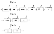
- FIG. 1a, 1b and 1c are system diagrams showing an embodiment of the method for treating biological treated water of the present invention.
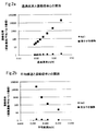
- FIG. 2a is a graph showing the relationship between the permeation flux and the concentration ratio in reverse osmosis membrane separation treatment using NaCl aqueous solution or water containing a high molecular weight organic material having an average molecular weight of 10,000 as raw water
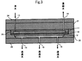
- FIG. It is a graph which shows the relationship between a linear velocity and concentration magnification. It is typical sectional drawing which shows the structure of the flat film cell used in the Example.
- the raw water subjected to the reverse osmosis membrane separation treatment by the reverse osmosis membrane device is water containing a high molecular weight organic substance having a molecular weight of 10,000 or more at a concentration of 0.01 ppm or more.
- water containing such a high molecular organic substance in an amount of 0.01 ppm or more, for example, 0.05 to 0.5 ppm and greatly reducing the permeation flux of the reverse osmosis membrane by passing water is used as raw water.
- recovered water from various wastewaters biologically treated water, particularly MBR treated water is preferably used.
- molecular weight fractionation is performed by chromatography such as LC-OCD (liquid chromatography-organic carbon measurement) or HPLC (high performance liquid chromatography). It can be measured using a device that measures TOC or the like. This concentration can also be measured by separating a substance having a molecular weight of 10,000 or more and a substance having a molecular weight of less than 10,000 using a UF membrane having a fractional molecular weight of 10,000 in advance and performing TOC analysis.
- LC-OCD liquid chromatography-organic carbon measurement
- HPLC high performance liquid chromatography
- the spiral reverse osmosis membrane element loaded in the reverse osmosis membrane device according to the present invention has a raw water spacer for passing raw water on the primary side (one surface) of the flat membrane of the reverse osmosis membrane, and the secondary side A membrane unit in which a permeated water spacer for passing permeated water is placed on the other surface is wound into a spiral shape.
- the diameter of the spiral type reverse osmosis membrane element there is no particular limitation on the diameter of the spiral type reverse osmosis membrane element, and 4 inch, 8 inch and 16 inch are provided. Generally, an 8 inch spiral type reverse osmosis membrane element is used. Yes.
- the length of the element is usually about 1 m, but is not limited to this.
- the spiral type reverse osmosis membrane element used in the present invention is characterized by having a membrane area satisfying the following formula (1).
- n represents the diameter (inch) of the reverse osmosis membrane element.
- the membrane area of the spiral reverse osmosis membrane element does not satisfy the above formula (1) and the membrane area (m 2 ) is smaller than n 2 ⁇ (11/16), the permeation flux at the same permeate flow rate can be reduced. Cannot be achieved with the object of the present invention.
- the membrane area (m 2 ) of the spiral-type reverse osmosis membrane element is particularly preferably n 2 ⁇ 11/16 or more, and particularly preferably n 2 ⁇ 13/16. In order to ensure the required amount of reverse osmosis membrane, raw water spacer and permeated water spacer, the membrane area is n 2 ⁇ 16/16 or less.
- the material of the reverse osmosis membrane is not particularly limited, but an aromatic polyamide membrane synthesized on a substrate using phenylenediamine and acid chloride is preferred because a membrane with a high removal rate is preferred.
- the thickness of the reverse osmosis membrane is usually in the range of 0.1 to 0.15 mm.
- the shape of the raw water spacer and the permeated water spacer is not particularly limited, but a plurality of wires having the same or different diameters made of resin such as polyethylene or polypropylene are arranged at equal intervals, and an angle of 45 to 90 degrees. In general, mesh spacers stacked so as to cross each other are generally used.
- raw water spacers that are generally employed include those with a thickness of 0.69 mm (26 mil), 0.71 mm (28 mil), and 0.86 mm (34 mil).
- a raw water spacer having a thickness of 0.6 mm or less, for example, about 0.2 to 0.6 mm. If the thickness of the raw water spacer is too thick, the membrane area per element becomes small and the above formula (1) cannot be satisfied. When the thickness of the raw water spacer is too thin, blockage of the flow path due to turbidity becomes a problem.
- the porosity of the mesh raw water spacer is preferably 60 to 95%, and the mesh size is preferably 1.0 to 4.0 mm.
- a mesh-shaped raw water spacer having such a porosity and mesh size can provide a mixing effect of raw water while ensuring sufficient water permeability and contribute to suppression of concentration polarization.
- the porosity is a percentage of a value obtained by dividing the space volume minus the volume of the wire by the space volume.
- the size of the mesh is the distance between the wire rods.
- the thickness of the permeate spacer is not particularly limited, but is preferably 0.1 to 0.25 mm. If the thickness of the permeated water spacer is too thick, the membrane area per element becomes small as in the case of the raw water spacer, and if it is too thin, the differential pressure increases and the amount of permeated water decreases.
- the reverse osmosis membrane device using the spiral reverse osmosis membrane element having the membrane area as described above is operated at a permeation flux of 0.6 m / d or less.
- the pure water permeation flux at the standard operating pressure of the reverse osmosis membrane device is 0.7 to 0.85 m / d, and when raw water containing inorganic salts and organic substances is passed, 0.5 to 0. Usually, it is set to about 7 m / d.
- the present inventor has confirmed that a polymer organic substance having a molecular weight of 10,000 or more is a substance that contaminates a reverse osmosis membrane, and that the permeation flux decreases significantly when the membrane surface concentration of the polymer organic substance concentration exceeds 1 ppm. Confirmed experimentally.
- the present inventor has found that in raw water containing a high molecular weight organic compound having a molecular weight of 10,000 or more in an amount of 0.01 ppm or more, the permeation flux decreases significantly when the concentration ratio of the membrane surface concentration exceeds 100 times. In order to prevent the concentration rate from exceeding 100 times, the permeation flux needs to be 0.6 m / d or less.
- the reverse osmosis membrane device is operated at a permeation flux of 0.6 m / d or less, preferably 0.45 m / d or less.
- the permeation flux is preferably 0.2 m / d or more.
- the flow rate of concentrated water is usually 2.0 to 8.0 m 3 / h in the case of an 8-inch spiral reverse osmosis membrane element, and the linear velocity at this time is 0.05 to 0.15 m / s.
- the line speed of the concentrated water is preferably maintained at 0.1 m / s or more, although it depends on the permeation flux, from the viewpoint of not increasing the membrane surface concentration.
- the linear velocity is lower than 0.1 m / s, the concentration ratio of the membrane surface exceeds 100 times, and the permeation flux is significantly reduced, which is not preferable.
- a more preferable linear velocity is 0.1 to 0.2 m / s.
- FIG. 1a, 1b and 1c are system diagrams showing an embodiment of the method for treating biologically treated water of the present invention using the reverse osmosis membrane apparatus of the present invention.
- the biologically treated water is aerobic and / or anaerobic biological treatment means 1, coagulation treatment means 2, solid-liquid separation means 3 such as pressurized flotation, filtration means 4, safety filter 5, and reverse osmosis membrane device 6. Is processed.
- FIG. 1b water obtained by solid-liquid separation of the treated water of the biological treatment means 1 directly by the filtration means 4 such as a membrane filtration apparatus is introduced into the reverse osmosis membrane apparatus 6 to perform reverse osmosis membrane separation treatment.
- mold membrane separator) 7 is directly introduce
- the method of the present invention is not limited to these methods.
- the membrane area per element can be increased, and flux reduction due to fouling can be suppressed. If the thickness of the raw water spacer is too thin, for example, if it is 0.2 mm or less, the water flow resistance increases and the risk of blockage due to turbidity increases.
- Example 1 Assuming an 8-inch spiral reverse osmosis membrane element with a membrane area of 44.0 m 2, a flat membrane is cut out from Nitto Denko's reverse osmosis membrane “ES20” (thickness 0.13 mm) to a width of 50 mm ⁇ length of 800 mm, and the thickness is 0 3 together with a 65 mm polypropylene mesh raw water spacer (porosity 92%, mesh size 2.6 mm) and a 10 mm thick ceramic (porous ceramic sintered body) permeated water spacer shown in FIG. Attached to the cell.
- the raw water spacer 11 and the permeated water spacer 12 are reversed in a space formed by combining the flow path forming members 21, 22, 23 made of acrylic and the pressure-resistant reinforcing members 24, 25 made of SUS.
- the laminated membrane unit is held via the osmotic membrane 10.
- the raw water flows into the primary side of the reverse osmosis membrane 10 from the raw water inlet 13 and flows along the raw water spacer 11, and the permeated water that has permeated the reverse osmosis membrane 10 in the meantime passes through the permeate spacer 12 and passes through the permeate outlet 15. Taken from.
- the concentrated water is taken out from the concentrated water outlet 14.
- the permeate flow rate was 0.6 m / d
- the flow rate of concentrated water was 0.11 m / s with a linear flow rate
- the permeate amount after 500 hours was examined.
- the initial permeated water amount in terms of 8 inch elements was 1.10 m 3 / h, and the initial concentrated water amount was 5.66 m 3 / h.
- the concentration of the high molecular organic substance having a molecular weight of 10,000 or more in the raw water was 0.05 ppm.
- the results are shown in Table 3.
- Example 1 Assuming an 8-inch reverse osmosis membrane element having a membrane area of 37.1 m 2 , the same test as in Example 1 was performed except that a polypropylene raw water spacer having a thickness of 0.86 mm was used, and the amount of permeated water after 500 hours was examined. . The initial permeated water amount in terms of 8 inch elements was 0.93 m 3 / h, and the initial concentrated water amount was 6.32 m 3 / h. The results are shown in Table 3.
- Example 2 The same test as in Example 1 was performed except that the permeation flux was 0.70 m / d, and the permeated water amount after 500 hours was examined.
- the initial permeate flow rate in terms of 8-inch elements was 1.28 m 3 / h, and the initial concentrated water flow rate was 5.66 m 3 / h.
- Table 3 The results are shown in Table 3.
- Comparative Example 3 The same test as in Comparative Example 1 was conducted except that the permeation flux was 0.70 m / d, and the permeated water amount after 500 hours was examined.
- Example 2 A test similar to Example 1 was conducted except that the concentrated water flow rate was 0.09 m / s, and the permeated water amount after 500 hours was examined.
- the results are shown in Table 3.
- Comparative Example 4 The same test as in Comparative Example 1 was conducted except that the concentrated water flow rate was 0.09 m / s, and the permeated water amount after 500 hours was examined. The initial permeated water amount in terms of 8 inch elements was 0.93 m 3 / h, and the initial concentrated water amount was 5.17 m 3 / h. The results are shown in Table 3.
- Comparative Example 5 The same test as in Comparative Example 2 was conducted except that the concentrated water flow rate was 0.09 m / s, and the permeated water amount after 500 hours was examined.
- Table 3 The results are shown in Table 3.
- Example 3 Assuming an 8-inch spiral reverse osmosis membrane element with a membrane area of 50.7 m 2 , the same test as in Example 2 was performed except that a polypropylene raw water spacer with a thickness of 0.50 mm was used. Examined. The initial permeate flow rate in terms of an 8-inch element was 1.27 m 3 / h, and the initial concentrated water flow rate was 4.11 m 3 / h. The results are shown in Table 3.
- Example 4 Assuming an 8-inch reverse osmosis membrane element having a membrane area of 56.4 m 2 , the same test as in Example 2 was performed except that a polypropylene raw water spacer having a thickness of 0.40 mm was used, and the amount of permeated water after 500 hours was examined. .
- the initial permeate flow rate in terms of 8-inch elements was 1.41 m 3 / h, and the initial concentrated water flow rate was 3.65 m 3 / h.
- Table 3 The results are shown in Table 3.
- Example 5 A test was conducted in the same manner as in Example 3 except that the permeation flux was 0.50 m / d and the concentrated water flow rate was 0.11 m / s with the flow rate of the concentrated water being linear, and the amount of permeated water after 500 hours was examined.
- the results are shown in Table 3.
- Example 6 A test was conducted in the same manner as in Example 4 except that the permeation flux was 0.45 m / d and the flow rate of the concentrated water was 0.11 m / s with the linear flow rate being the linear velocity, and the permeated water amount after 500 hours was examined.
- the results are shown in Table 3.
- Example 7 Assuming an 8-inch spiral reverse osmosis membrane element with a membrane area of 63.6 m 2 , a polypropylene raw water spacer with a thickness of 0.30 mm was used, and the permeation flux was 0.40 m / d. A test was conducted and the amount of permeated water after 500 hours was examined. The initial permeate flow rate 8 inch elements terms of 1.06 m 3 / h, the initial concentration water was 3.78m 3 / h. The results are shown in Table 3.
- Comparative Example 7 A test similar to Comparative Example 3 was performed except that water having a molecular weight of 10,000 or more and a high molecular organic substance concentration of 0.005 ppm was used as raw water, and the amount of permeated water after 500 hours was examined.
- the results are shown in Table 3.
- a high permeated water amount can be stably obtained even after 500 hours.
- the permeated water amount did not decrease after 500 hours.
- the permeated water amount does not decrease so much, but since the initial permeated water amount is low, the permeated water amount obtained after 500 hours is low.
- Comparative Examples 2 and 5 the initial amount of permeated water is large, but the amount of permeated water obtained after 500 hours is low because the decrease in the amount of permeated water is large.
- Comparative Examples 3 and 6 the decrease in the amount of permeate is large, and the amount of permeate obtained after 500 hours is low.
- Comparative Example 7 when the concentration of the high molecular weight organic material having a molecular weight of 10,000 or more in the raw water was low, the permeated water amount gradually decreased.
- the present invention can be applied to various reverse osmosis membrane devices used for seawater desalination, ultrapure water production, industrial water treatment, wastewater recovery treatment, etc., and in particular, treats biologically treated water, especially MBR treated water. It is suitably applied to a reverse osmosis membrane device.
Landscapes
- Chemical & Material Sciences (AREA)
- Engineering & Computer Science (AREA)
- Water Supply & Treatment (AREA)
- Chemical Kinetics & Catalysis (AREA)
- Life Sciences & Earth Sciences (AREA)
- Hydrology & Water Resources (AREA)
- Environmental & Geological Engineering (AREA)
- Organic Chemistry (AREA)
- Nanotechnology (AREA)
- Separation Using Semi-Permeable Membranes (AREA)
- Biodiversity & Conservation Biology (AREA)
- Microbiology (AREA)
Abstract
Description
1)膜の透過流束を小さくすると濃度分極は小さくなる。
2)膜表面の通水線速を大きくすると濃度分極は小さくなる。
3)溶質の分子量が大きくなると濃度分極が大きくなる。
本発明者らはまた、膜汚染によるファウリングを引き起こす原因物質が、分子量10,000以上の高分子有機物、特に多糖類、たんぱく質のような生物代謝物であること、それらの高分子有機物が濃度分極によって膜面濃度が上昇した際に、透過流束及び透過水量の低下が顕著になることをつきとめた。
膜面積(m2)≧n2×(11/16) …(1)
ただし、nは逆浸透膜エレメントの直径(インチ)を表す。
膜面積(m2)≧n2×(11/16) …(1)
ただし、nは逆浸透膜エレメントの直径(インチ)を表す。
本発明において、逆浸透膜装置で逆浸透膜分離処理する原水は、分子量10,000以上の高分子有機物を0.01ppm以上の濃度で含有する水である。分子量10,000以上の高分子有機物、特に多糖類、たんぱく質のような生物代謝物は、膜を汚染し易く、透過流束の低下の原因となり易い。本発明においては、このような高分子有機物を0.01ppm以上、例えば0.05~0.5ppm含み、通水により逆浸透膜の透過流束を大きく低下させる水を原水とする。
本発明における逆浸透膜装置に装填されるスパイラル型逆浸透膜エレメントは、逆浸透膜の平膜の一次側(一方の面)に原水を通水するための原水スペーサを配置し、二次側(他方の面)に透過水を通水するための透過水スペーサを配置した膜ユニットを巻回してスパイラル状にしたものである。
膜面積(m2)≧n2×(11/16) …(1)
ただし、nは逆浸透膜エレメントの直径(インチ)を表す。
本発明においては、上述のような膜面積を有するスパイラル型逆浸透膜エレメントを用いた逆浸透膜装置を透過流束0.6m/d以下で運転する。
本発明の逆浸透膜装置は、特に生物処理水の逆浸透膜分処理に好適に用いられる。
図1aでは、生物処理水は、好気及び/又は嫌気性生物処理手段1、凝集処理手段2、加圧浮上等の固液分離手段3、濾過手段4、保安フィルター5及び逆浸透膜装置6で処理される。図1bでは、生物処理手段1の処理水を直接膜濾過装置等の濾過手段4で固液分離した水を逆浸透膜装置6に導入して逆浸透膜分離処理する。図1cでは、MBR(浸漬型膜分離装置)7の処理水を直接逆浸透膜装置6に導入して処理する。本発明方法は、これらの方法に限定されない。
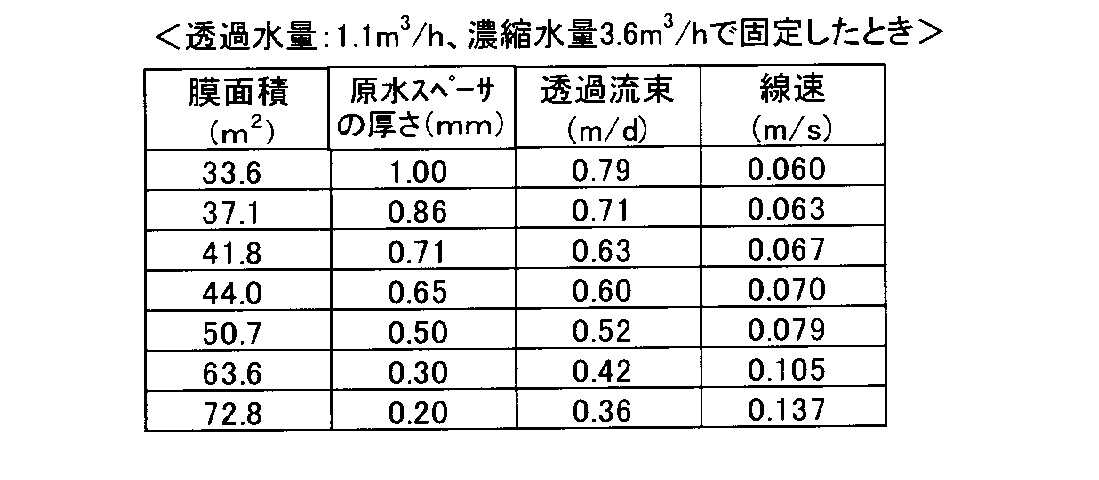
直径8インチのスパイラル型逆浸透膜エレメント(n2×(11/16)=44)における原水スペーサの厚さと膜面積の関係と、流量一定時の透過流束と線速との関係を、以下の表1,2に示す。

逆浸透膜分離処理において、NaCl水溶液、又は平均分子量10,000の高分子有機物を含む水を原水とする場合の透過流束又は平均線速と濃縮倍率(膜面濃度/平均バルク濃度)の関係を解析した結果、図2a,2bに示す関係が得られた。
図2a,2bより、高分子の種類によって多少の差異はあるものの、総じてNaClなどの分子量の小さい物質と比較して、高分子有機物の膜面濃度は、透過流束の増大、平均線速の低下により、著しく増加することが分かる。
膜面積44.0m2の8インチスパイラル型逆浸透膜エレメントを想定し、日東電工製逆浸透膜「ES20」(厚さ0.13mm)から平膜を幅50mm×長さ800mmに切り抜き、厚み0.65mmのポリプロピレン製メッシュ状原水スペーサ(空孔率92%、メッシュの大きさ2.6mm)及び厚み10mmのセラミックス(多孔質セラミックス焼結体)製透過水スペーサとともに図3に示す試験用平膜セルに取り付けた。
膜面積37.1m2の8インチ逆浸透膜エレメントを想定し、厚み0.86mmのポリプロピレン製原水スペーサを用いた以外は実施例1と同様の試験を行い、500時間後の透過水量を調べた。8インチエレメント換算の初期透過水量は0.93m3/h、初期濃縮水量は6.32m3/hであった。結果を表3に示す。
透過流束を0.70m/dとする以外は実施例1と同様の試験を行い、500時間後の透過水量を調べた。8インチエレメント換算の初期透過水量は1.28m3/h、初期濃縮水量は5.66m3/hであった。結果を表3に示す。
透過流束を0.70m/dとする以外は比較例1と同様の試験を行い、500時間後の透過水量を調べた。8インチエレメント換算の初期透過水量は1.08m3/h、初期濃縮水量は6.32m3/hであった。結果を表3に示す。
濃縮水流量を線速として0.09m/sで通水する以外は実施例1と同様の試験を行い、500時間後の透過水量を調べた。8インチエレメント換算の初期透過水量は1.10m3/h、初期濃縮水量は4.63m3/hであった。結果を表3に示す。
濃縮水流量を線速として0.09m/sで通水する以外は比較例1と同様の試験を行い、500時間後の透過水量を調べた。8インチエレメント換算の初期透過水量は0.93m3/h、初期濃縮水量は5.17m3/hであった。結果を表3に示す。
濃縮水流量を線速として0.09m/sで通水する以外は比較例2と同様の試験を行い、500時間後の透過水量を調べた。8インチエレメント換算の初期透過水量は1.28m3/h、初期濃縮水量は4.63m3/hであった。結果を表3に示す。
透過流束を0.70m/d、濃縮水流量を線速として0.09m/sで通水する以外は比較例1と同様の試験を行い、500時間後の透過水量を調べた。8インチエレメント換算の初期透過流量は1.08m3/h、初期濃縮水量は5.17m3/hであった。結果を表3に示す。
膜面積50.7m2の8インチスパイラル型逆浸透膜エレメントを想定し、厚み0.50mmのポリプロピレン製原水スペーサを用いた以外は実施例2と同様の試験を行い、500時間後の透過水量を調べた。8インチエレメント換算の初期透過水量は1.27m3/h、初期濃縮水量は4.11m3/hであった。結果を表3に示す。
膜面積56.4m2の8インチ逆浸透膜エレメントを想定し、厚み0.40mmのポリプロピレン製原水スペーサを用いた以外は実施例2と同様の試験を行い、500時間後の透過水量を調べた。8インチエレメント換算の初期透過水量は1.41m3/h、初期濃縮水量は3.65m3/hであった。結果を表3に示す。
透過流束を0.50m/d、濃縮水流量を線速として0.11m/sで通水する以外は実施例3と同様の試験を行い、500時間後の透過水量を調べた。8インチエレメント換算の初期透過水量は1.06m3/h、初期濃縮水量は5.02m3/hであった。結果を表3に示す。
透過流束を0.45m/d、濃縮水流量を線速として0.11m/sで通水する以外は実施例4と同様の試験を行い、500時間後の透過水量を調べた。8インチエレメント換算の初期透過水量は1.06m3/h、初期濃縮水量は4.47m3/hであった。結果を表3に示す。
膜面積63.6m2の8インチスパイラル型逆浸透膜エレメントを想定し、厚み0.30mmのポリプロピレン製原水スペーサを用い、透過流束を0.40m/dとした以外は実施例1と同様の試験を行い、500時間後の透過水量を調べた。8インチエレメント換算の初期透過水量は1.06m3/h、初期濃縮水量は3.78m3/hであった。結果を表3に示す。
分子量10,000以上の高分子有機物の濃度が0.005ppmの水を原水として使用した以外は、比較例3と同様の試験を行い、500時間後の透過水量を調べた。8インチエレメント換算の初期透過水量は1.08m3/h、初期濃縮水量は6.32m3/hであった。結果を表3に示す。
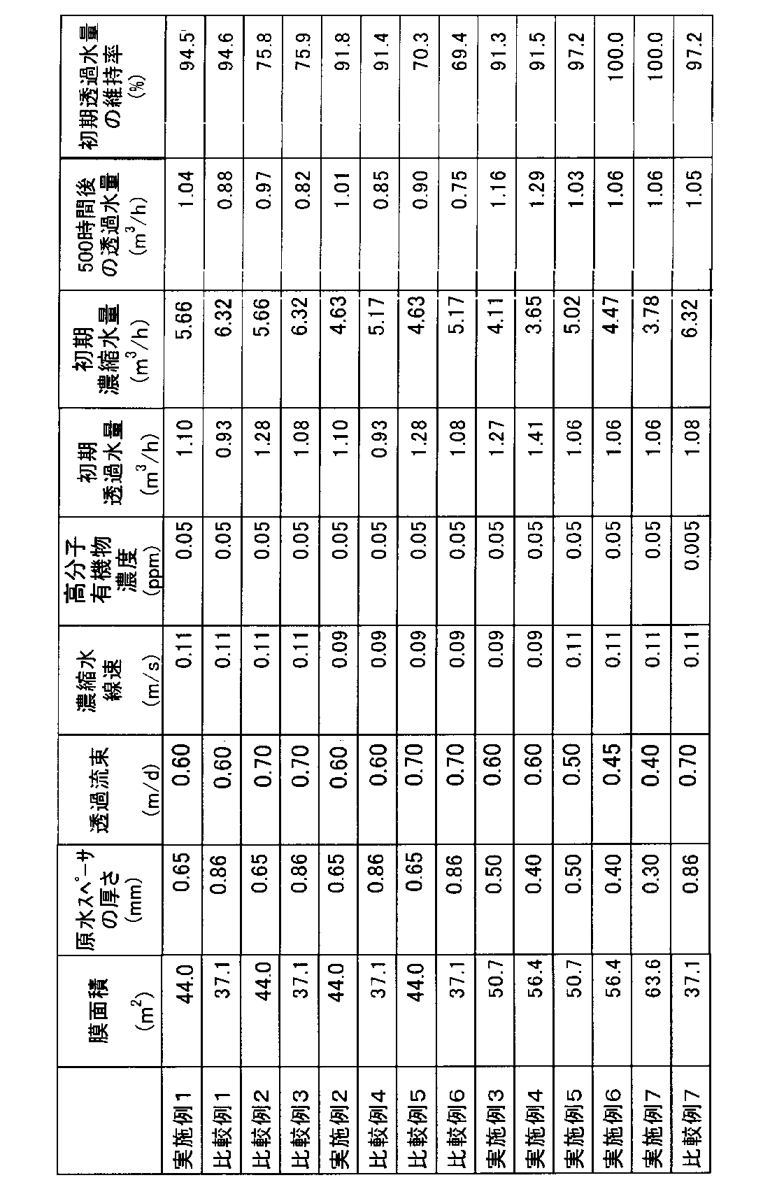
実施例1~7では、500時間経過しても安定して高い透過水量を得ることができる。特に実施例6、7は500時間経過後では透過水量低下が起こらなかった。比較例1、4は透過水量の低下はそれほど起きないが、初期の透過水量が低いため、500時間後においても得られる透過水量は低い。比較例2,5は初期の透過水量は大きいが、透過水量の低下が大きいため、500時間後に得られる透過水量は低い。比較例3,6も透過水量の低下が大きく、500時間後に得られる透過水量は低い。比較例7のように、原水の分子量10,000以上の高分子有機物濃度が低い場合は、透過水量の低下が緩やかであった。
本出願は、2013年2月20日付で出願された日本特許出願2013-031032に基づいており、その全体が引用により援用される。
2 凝集処理手段
3 固液分離手段
4 濾過手段
5 保安フィルター
6 逆浸透膜装置
7 MBR(浸漬型膜分離装置)
10 逆浸透膜
11 原水スペーサ
12 透過水スペーサ
Claims (7)
- 高分子有機物を含有する水を原水として処理する逆浸透膜装置の運転方法において、該原水が分子量10,000以上の高分子有機物を0.01ppm以上の濃度で含有し、該逆浸透膜装置は、下記式(1)を満たす膜面積を有するスパイラル型逆浸透膜エレメントを有し、該逆浸透膜装置を透過流束0.6m/d以下で運転することを特徴とする逆浸透膜装置の運転方法。
膜面積(m2)≧n2×(11/16) …(1)
ただし、nは逆浸透膜エレメントの直径(インチ)を表す。 - 前記透過流束が0.45m/d以下であることを特徴とする請求項1に記載の逆浸透膜装置の運転方法。
- 線速0.1m/s以上の濃縮水流量で運転することを特徴とする請求項1又は2に記載の逆浸透膜装置の運転方法。
- 前記逆浸透膜エレメントの直径nが8インチであることを特徴とする請求項1ないし3のいずれか1項に記載の逆浸透膜装置の運転方法。
- 前記原水がMBR処理水であることを特徴とする請求項1ないし4のいずれか1項に記載の逆浸透膜装置の運転方法。
- 分子量10,000以上の高分子有機物を0.01ppm以上の濃度で含有する水を原水として処理する逆浸透膜装置であって、下記式(1)を満たす膜面積を有するスパイラル型逆浸透膜エレメントを有し、透過流束0.6m/d以下で運転されることを特徴とする逆浸透膜装置。
膜面積(m2)≧n2×(11/16) …(1)
ただし、nは逆浸透膜エレメントの直径(インチ)を表す。 - 生物処理水を請求項6に記載の逆浸透膜装置で逆浸透膜分離処理することを特徴とする生物処理水の処理方法。
Priority Applications (4)
| Application Number | Priority Date | Filing Date | Title |
|---|---|---|---|
| CN201480009118.9A CN105008286B (zh) | 2013-02-20 | 2014-02-14 | 逆渗透膜装置的运转方法以及逆渗透膜装置 |
| US14/766,355 US10252219B2 (en) | 2013-02-20 | 2014-02-14 | Method for operating reverse osmosis membrane device, and reverse osmosis membrane device |
| SG11201506179UA SG11201506179UA (en) | 2013-02-20 | 2014-02-14 | Method for operating reverse osmosis membrane device, and reverse osmosis membrane device |
| KR1020157021769A KR102009068B1 (ko) | 2013-02-20 | 2014-02-14 | 역침투막 장치의 운전 방법, 및 역침투막 장치 |
Applications Claiming Priority (2)
| Application Number | Priority Date | Filing Date | Title |
|---|---|---|---|
| JP2013-031032 | 2013-02-20 | ||
| JP2013031032A JP5828328B2 (ja) | 2013-02-20 | 2013-02-20 | 逆浸透膜装置の運転方法、及び逆浸透膜装置 |
Publications (1)
| Publication Number | Publication Date |
|---|---|
| WO2014129398A1 true WO2014129398A1 (ja) | 2014-08-28 |
Family
ID=51391191
Family Applications (1)
| Application Number | Title | Priority Date | Filing Date |
|---|---|---|---|
| PCT/JP2014/053471 Ceased WO2014129398A1 (ja) | 2013-02-20 | 2014-02-14 | 逆浸透膜装置の運転方法、及び逆浸透膜装置 |
Country Status (7)
| Country | Link |
|---|---|
| US (1) | US10252219B2 (ja) |
| JP (1) | JP5828328B2 (ja) |
| KR (1) | KR102009068B1 (ja) |
| CN (1) | CN105008286B (ja) |
| SG (1) | SG11201506179UA (ja) |
| TW (1) | TWI581858B (ja) |
| WO (1) | WO2014129398A1 (ja) |
Families Citing this family (9)
| Publication number | Priority date | Publication date | Assignee | Title |
|---|---|---|---|---|
| JP6554781B2 (ja) * | 2013-12-26 | 2019-08-07 | 栗田工業株式会社 | 逆浸透膜装置の運転方法、及び逆浸透膜装置 |
| US20190137210A1 (en) * | 2017-11-06 | 2019-05-09 | Larry E. Moore | Boresighter trainer for gun |
| WO2016027302A1 (ja) * | 2014-08-19 | 2016-02-25 | 栗田工業株式会社 | 逆浸透膜装置及びその運転方法 |
| JP6637232B2 (ja) * | 2014-11-13 | 2020-01-29 | 日東電工株式会社 | スパイラル型膜エレメント用透過側流路材、及びその製造方法 |
| JP7089352B2 (ja) * | 2016-09-16 | 2022-06-22 | 日東電工株式会社 | スパイラル型膜エレメント |
| KR102326947B1 (ko) * | 2016-09-21 | 2021-11-15 | 도레이 카부시키가이샤 | 분리막 엘리먼트 및 그 운전 방법 |
| KR102462859B1 (ko) * | 2018-05-21 | 2022-11-03 | 쿠리타 고교 가부시키가이샤 | 역침투 시스템의 진단 장치 |
| CN111908718A (zh) * | 2020-08-11 | 2020-11-10 | 浙江天行健水务有限公司 | 一种垃圾渗透液的深度处理方法 |
| WO2025104893A1 (ja) * | 2023-11-16 | 2025-05-22 | 株式会社Gsユアサメンブレン | スパイラルフィルタ |
Citations (5)
| Publication number | Priority date | Publication date | Assignee | Title |
|---|---|---|---|---|
| JPS61185400A (ja) * | 1985-02-12 | 1986-08-19 | Kurita Water Ind Ltd | し尿系汚水の処理装置 |
| JPH10230140A (ja) * | 1997-02-19 | 1998-09-02 | Nitto Denko Corp | スパイラル型膜エレメント |
| JP2000288542A (ja) * | 1999-04-09 | 2000-10-17 | Toray Ind Inc | スパイラル型逆浸透膜エレメント |
| JP2005111473A (ja) * | 2003-09-17 | 2005-04-28 | Nitto Denko Corp | 膜エレメント用シール材保持部材および膜エレメント |
| JP2009240902A (ja) * | 2008-03-31 | 2009-10-22 | Toray Ind Inc | 水処理方法および水処理装置 |
Family Cites Families (14)
| Publication number | Priority date | Publication date | Assignee | Title |
|---|---|---|---|---|
| JPH08108048A (ja) * | 1994-10-12 | 1996-04-30 | Toray Ind Inc | 逆浸透分離装置及び逆浸透分離方法 |
| JP4107724B2 (ja) | 1997-10-21 | 2008-06-25 | 日東電工株式会社 | スパイラル型膜エレメント |
| WO1999065594A1 (fr) * | 1998-06-18 | 1999-12-23 | Toray Industries, Inc. | Element en spirale de membrane d'osmose inverse, module de membrane d'osmose inverse utilisant cet element, dispositif et procede destines a la separation par osmose inverse integrant ce module |
| JP4583671B2 (ja) * | 2000-07-19 | 2010-11-17 | 日東電工株式会社 | スパイラル型膜エレメントおよびスパイラル型膜モジュールの運転方法および洗浄方法 |
| AU2001219539A1 (en) * | 2000-09-05 | 2002-03-22 | Wesley L. Bradford | Reverse osmosis membrane and process for making same |
| US6881336B2 (en) * | 2002-05-02 | 2005-04-19 | Filmtec Corporation | Spiral wound element with improved feed space |
| JP2004050005A (ja) * | 2002-07-18 | 2004-02-19 | Japan Organo Co Ltd | スパイラル型膜エレメント、逆浸透膜モジュール及び逆浸透膜装置 |
| US20050006295A1 (en) * | 2003-02-10 | 2005-01-13 | Upen Bharwada | Water treatment system |
| KR100789032B1 (ko) * | 2003-09-17 | 2007-12-26 | 닛토덴코 가부시키가이샤 | 막 요소용 시일 링 홀더 및 막 요소 |
| US7198719B2 (en) | 2004-09-03 | 2007-04-03 | Nitto Denko Corporation | Sealer holding member for membrane element and membrane element using the same |
| US20110290728A1 (en) * | 2010-05-25 | 2011-12-01 | General Electric Company | SWRO Pressure Vessel and Process That Increases Production and Product Quality and Avoids Scaling Problems |
| EP2633901A4 (en) * | 2010-10-26 | 2014-09-17 | Toray Industries | SEPARATE MEMBRANE, SEPARATE MEMBRANE ELEMENT AND METHOD FOR PRODUCING THE SEPARATE MEMBRANE |
| US20130146531A1 (en) * | 2011-12-09 | 2013-06-13 | General Electric Company | Feed spacers for spiral wound membrane element |
| CN102580557A (zh) * | 2012-03-12 | 2012-07-18 | 王丽华 | 一种低压降螺旋卷式膜元件 |
-
2013
- 2013-02-20 JP JP2013031032A patent/JP5828328B2/ja active Active
-
2014
- 2014-02-14 SG SG11201506179UA patent/SG11201506179UA/en unknown
- 2014-02-14 WO PCT/JP2014/053471 patent/WO2014129398A1/ja not_active Ceased
- 2014-02-14 US US14/766,355 patent/US10252219B2/en active Active
- 2014-02-14 CN CN201480009118.9A patent/CN105008286B/zh active Active
- 2014-02-14 KR KR1020157021769A patent/KR102009068B1/ko active Active
- 2014-02-19 TW TW103105471A patent/TWI581858B/zh active
Patent Citations (5)
| Publication number | Priority date | Publication date | Assignee | Title |
|---|---|---|---|---|
| JPS61185400A (ja) * | 1985-02-12 | 1986-08-19 | Kurita Water Ind Ltd | し尿系汚水の処理装置 |
| JPH10230140A (ja) * | 1997-02-19 | 1998-09-02 | Nitto Denko Corp | スパイラル型膜エレメント |
| JP2000288542A (ja) * | 1999-04-09 | 2000-10-17 | Toray Ind Inc | スパイラル型逆浸透膜エレメント |
| JP2005111473A (ja) * | 2003-09-17 | 2005-04-28 | Nitto Denko Corp | 膜エレメント用シール材保持部材および膜エレメント |
| JP2009240902A (ja) * | 2008-03-31 | 2009-10-22 | Toray Ind Inc | 水処理方法および水処理装置 |
Also Published As
| Publication number | Publication date |
|---|---|
| JP2014159015A (ja) | 2014-09-04 |
| SG11201506179UA (en) | 2015-09-29 |
| US20160016122A1 (en) | 2016-01-21 |
| US10252219B2 (en) | 2019-04-09 |
| JP5828328B2 (ja) | 2015-12-02 |
| CN105008286B (zh) | 2017-09-22 |
| TWI581858B (zh) | 2017-05-11 |
| KR20150120972A (ko) | 2015-10-28 |
| TW201500103A (zh) | 2015-01-01 |
| KR102009068B1 (ko) | 2019-08-08 |
| CN105008286A (zh) | 2015-10-28 |
Similar Documents
| Publication | Publication Date | Title |
|---|---|---|
| JP5828328B2 (ja) | 逆浸透膜装置の運転方法、及び逆浸透膜装置 | |
| KR102009550B1 (ko) | 다단 역침투막 장치 및 그 운전 방법 | |
| Singh et al. | Emerging membrane technology for sustainable water treatment | |
| US20020162784A1 (en) | Membrane separator | |
| JP6183213B2 (ja) | 造水方法および造水装置 | |
| CN105073652A (zh) | 淡水生产方法 | |
| JP3230490B2 (ja) | スパイラル型逆浸透膜エレメントおよびそれを用いた分離装置 | |
| WO2016027302A1 (ja) | 逆浸透膜装置及びその運転方法 | |
| JP6630689B2 (ja) | 水処理設備および水処理方法 | |
| Yaranal et al. | An analysis of the effects of pressure-assisted osmotic backwashing on the high recovery reverse osmosis system | |
| JP6036808B2 (ja) | 造水方法 | |
| Chakraborty et al. | Recent advances in membrane technology for the recovery and reuse of valuable resources | |
| JP6149489B2 (ja) | 逆浸透膜装置の運転方法 | |
| Gullinkala et al. | Membranes for water treatment applications–an overview | |
| JP2017518865A (ja) | 総溶存固体を流体から除去するための装置、システムおよび方法 | |
| Waterman | Bench-scale analysis of ultrafiltration membranes for investigating fouling by natural organic matter in surface water | |
| JP2019217504A (ja) | 水処理設備および水処理方法 | |
| Alonso | Rejection of Organic Micropollutants by Nanofiltration and Reverse Osmosis Membranes | |
| JP2013223847A (ja) | 水処理方法および水処理装置 | |
| JP2006218341A (ja) | 水処理方法および装置 | |
| Cartwright | Application of membrane separation technologies to wastewater reclamation and reuse | |
| JP2002336659A (ja) | 中空糸膜モジュール、水処理方法及び中空糸膜モジュールの長寿命化方法 | |
| JP2008207077A (ja) | インク含有排水の処理方法 | |
| JP2016093781A (ja) | 水処理方法及び水処理システム |
Legal Events
| Date | Code | Title | Description |
|---|---|---|---|
| 121 | Ep: the epo has been informed by wipo that ep was designated in this application |
Ref document number: 14753559 Country of ref document: EP Kind code of ref document: A1 |
|
| WWE | Wipo information: entry into national phase |
Ref document number: 14766355 Country of ref document: US |
|
| ENP | Entry into the national phase |
Ref document number: 20157021769 Country of ref document: KR Kind code of ref document: A |
|
| NENP | Non-entry into the national phase |
Ref country code: DE |
|
| 122 | Ep: pct application non-entry in european phase |
Ref document number: 14753559 Country of ref document: EP Kind code of ref document: A1 |