WO2014128961A1 - 空気調和装置 - Google Patents
空気調和装置 Download PDFInfo
- Publication number
- WO2014128961A1 WO2014128961A1 PCT/JP2013/054751 JP2013054751W WO2014128961A1 WO 2014128961 A1 WO2014128961 A1 WO 2014128961A1 JP 2013054751 W JP2013054751 W JP 2013054751W WO 2014128961 A1 WO2014128961 A1 WO 2014128961A1
- Authority
- WO
- WIPO (PCT)
- Prior art keywords
- heat medium
- heat
- refrigerant
- heat exchanger
- switching device
- Prior art date
Links
- 238000010438 heat treatment Methods 0.000 claims abstract description 75
- 239000003507 refrigerant Substances 0.000 claims description 246
- 238000001816 cooling Methods 0.000 claims description 79
- 238000004378 air conditioning Methods 0.000 claims description 37
- 238000012546 transfer Methods 0.000 claims description 26
- XLYOFNOQVPJJNP-UHFFFAOYSA-N water Substances O XLYOFNOQVPJJNP-UHFFFAOYSA-N 0.000 claims description 14
- 238000004891 communication Methods 0.000 claims description 9
- 230000000694 effects Effects 0.000 claims description 8
- 230000002093 peripheral effect Effects 0.000 claims description 7
- 230000002528 anti-freeze Effects 0.000 claims description 4
- 230000008859 change Effects 0.000 claims description 3
- 239000000203 mixture Substances 0.000 claims description 3
- 239000000654 additive Substances 0.000 claims description 2
- 230000000996 additive effect Effects 0.000 claims description 2
- 239000007789 gas Substances 0.000 description 18
- 238000010586 diagram Methods 0.000 description 13
- 238000012423 maintenance Methods 0.000 description 10
- 239000007788 liquid Substances 0.000 description 7
- 230000009471 action Effects 0.000 description 5
- 239000002826 coolant Substances 0.000 description 4
- 238000012545 processing Methods 0.000 description 4
- 238000009434 installation Methods 0.000 description 3
- ATUOYWHBWRKTHZ-UHFFFAOYSA-N Propane Chemical compound CCC ATUOYWHBWRKTHZ-UHFFFAOYSA-N 0.000 description 2
- 239000012267 brine Substances 0.000 description 2
- 238000001514 detection method Methods 0.000 description 2
- 230000006872 improvement Effects 0.000 description 2
- 239000011259 mixed solution Substances 0.000 description 2
- 230000004048 modification Effects 0.000 description 2
- 238000012986 modification Methods 0.000 description 2
- HPALAKNZSZLMCH-UHFFFAOYSA-M sodium;chloride;hydrate Chemical compound O.[Na+].[Cl-] HPALAKNZSZLMCH-UHFFFAOYSA-M 0.000 description 2
- 239000007787 solid Substances 0.000 description 2
- 238000004781 supercooling Methods 0.000 description 2
- 238000011144 upstream manufacturing Methods 0.000 description 2
- 230000000903 blocking effect Effects 0.000 description 1
- 238000007664 blowing Methods 0.000 description 1
- 230000005494 condensation Effects 0.000 description 1
- 238000009833 condensation Methods 0.000 description 1
- 239000000470 constituent Substances 0.000 description 1
- 238000010276 construction Methods 0.000 description 1
- 230000003292 diminished effect Effects 0.000 description 1
- 238000001704 evaporation Methods 0.000 description 1
- 230000008020 evaporation Effects 0.000 description 1
- 239000012530 fluid Substances 0.000 description 1
- 230000017525 heat dissipation Effects 0.000 description 1
- 238000009413 insulation Methods 0.000 description 1
- 239000001294 propane Substances 0.000 description 1
- 230000005855 radiation Effects 0.000 description 1
- 238000005057 refrigeration Methods 0.000 description 1
- 239000011347 resin Substances 0.000 description 1
- 229920005989 resin Polymers 0.000 description 1
- 239000000126 substance Substances 0.000 description 1
- 230000001052 transient effect Effects 0.000 description 1
- 238000009423 ventilation Methods 0.000 description 1
- 238000010792 warming Methods 0.000 description 1
- 239000002918 waste heat Substances 0.000 description 1
Images


Classifications
-
- F—MECHANICAL ENGINEERING; LIGHTING; HEATING; WEAPONS; BLASTING
- F24—HEATING; RANGES; VENTILATING
- F24F—AIR-CONDITIONING; AIR-HUMIDIFICATION; VENTILATION; USE OF AIR CURRENTS FOR SCREENING
- F24F5/00—Air-conditioning systems or apparatus not covered by F24F1/00 or F24F3/00, e.g. using solar heat or combined with household units such as an oven or water heater
- F24F5/0007—Air-conditioning systems or apparatus not covered by F24F1/00 or F24F3/00, e.g. using solar heat or combined with household units such as an oven or water heater cooling apparatus specially adapted for use in air-conditioning
- F24F5/001—Compression cycle type
-
- F—MECHANICAL ENGINEERING; LIGHTING; HEATING; WEAPONS; BLASTING
- F16—ENGINEERING ELEMENTS AND UNITS; GENERAL MEASURES FOR PRODUCING AND MAINTAINING EFFECTIVE FUNCTIONING OF MACHINES OR INSTALLATIONS; THERMAL INSULATION IN GENERAL
- F16K—VALVES; TAPS; COCKS; ACTUATING-FLOATS; DEVICES FOR VENTING OR AERATING
- F16K11/00—Multiple-way valves, e.g. mixing valves; Pipe fittings incorporating such valves
- F16K11/02—Multiple-way valves, e.g. mixing valves; Pipe fittings incorporating such valves with all movable sealing faces moving as one unit
- F16K11/08—Multiple-way valves, e.g. mixing valves; Pipe fittings incorporating such valves with all movable sealing faces moving as one unit comprising only taps or cocks
- F16K11/085—Multiple-way valves, e.g. mixing valves; Pipe fittings incorporating such valves with all movable sealing faces moving as one unit comprising only taps or cocks with cylindrical plug
-
- F—MECHANICAL ENGINEERING; LIGHTING; HEATING; WEAPONS; BLASTING
- F24—HEATING; RANGES; VENTILATING
- F24F—AIR-CONDITIONING; AIR-HUMIDIFICATION; VENTILATION; USE OF AIR CURRENTS FOR SCREENING
- F24F1/00—Room units for air-conditioning, e.g. separate or self-contained units or units receiving primary air from a central station
- F24F1/06—Separate outdoor units, e.g. outdoor unit to be linked to a separate room comprising a compressor and a heat exchanger
- F24F1/26—Refrigerant piping
- F24F1/32—Refrigerant piping for connecting the separate outdoor units to indoor units
-
- F—MECHANICAL ENGINEERING; LIGHTING; HEATING; WEAPONS; BLASTING
- F24—HEATING; RANGES; VENTILATING
- F24F—AIR-CONDITIONING; AIR-HUMIDIFICATION; VENTILATION; USE OF AIR CURRENTS FOR SCREENING
- F24F3/00—Air-conditioning systems in which conditioned primary air is supplied from one or more central stations to distributing units in the rooms or spaces where it may receive secondary treatment; Apparatus specially designed for such systems
- F24F3/06—Air-conditioning systems in which conditioned primary air is supplied from one or more central stations to distributing units in the rooms or spaces where it may receive secondary treatment; Apparatus specially designed for such systems characterised by the arrangements for the supply of heat-exchange fluid for the subsequent treatment of primary air in the room units
- F24F3/065—Air-conditioning systems in which conditioned primary air is supplied from one or more central stations to distributing units in the rooms or spaces where it may receive secondary treatment; Apparatus specially designed for such systems characterised by the arrangements for the supply of heat-exchange fluid for the subsequent treatment of primary air in the room units with a plurality of evaporators or condensers
-
- F—MECHANICAL ENGINEERING; LIGHTING; HEATING; WEAPONS; BLASTING
- F25—REFRIGERATION OR COOLING; COMBINED HEATING AND REFRIGERATION SYSTEMS; HEAT PUMP SYSTEMS; MANUFACTURE OR STORAGE OF ICE; LIQUEFACTION SOLIDIFICATION OF GASES
- F25B—REFRIGERATION MACHINES, PLANTS OR SYSTEMS; COMBINED HEATING AND REFRIGERATION SYSTEMS; HEAT PUMP SYSTEMS
- F25B13/00—Compression machines, plants or systems, with reversible cycle
-
- F—MECHANICAL ENGINEERING; LIGHTING; HEATING; WEAPONS; BLASTING
- F25—REFRIGERATION OR COOLING; COMBINED HEATING AND REFRIGERATION SYSTEMS; HEAT PUMP SYSTEMS; MANUFACTURE OR STORAGE OF ICE; LIQUEFACTION SOLIDIFICATION OF GASES
- F25B—REFRIGERATION MACHINES, PLANTS OR SYSTEMS; COMBINED HEATING AND REFRIGERATION SYSTEMS; HEAT PUMP SYSTEMS
- F25B49/00—Arrangement or mounting of control or safety devices
- F25B49/02—Arrangement or mounting of control or safety devices for compression type machines, plants or systems
-
- F—MECHANICAL ENGINEERING; LIGHTING; HEATING; WEAPONS; BLASTING
- F25—REFRIGERATION OR COOLING; COMBINED HEATING AND REFRIGERATION SYSTEMS; HEAT PUMP SYSTEMS; MANUFACTURE OR STORAGE OF ICE; LIQUEFACTION SOLIDIFICATION OF GASES
- F25B—REFRIGERATION MACHINES, PLANTS OR SYSTEMS; COMBINED HEATING AND REFRIGERATION SYSTEMS; HEAT PUMP SYSTEMS
- F25B2313/00—Compression machines, plants or systems with reversible cycle not otherwise provided for
- F25B2313/003—Indoor unit with water as a heat sink or heat source
-
- F—MECHANICAL ENGINEERING; LIGHTING; HEATING; WEAPONS; BLASTING
- F25—REFRIGERATION OR COOLING; COMBINED HEATING AND REFRIGERATION SYSTEMS; HEAT PUMP SYSTEMS; MANUFACTURE OR STORAGE OF ICE; LIQUEFACTION SOLIDIFICATION OF GASES
- F25B—REFRIGERATION MACHINES, PLANTS OR SYSTEMS; COMBINED HEATING AND REFRIGERATION SYSTEMS; HEAT PUMP SYSTEMS
- F25B2313/00—Compression machines, plants or systems with reversible cycle not otherwise provided for
- F25B2313/023—Compression machines, plants or systems with reversible cycle not otherwise provided for using multiple indoor units
- F25B2313/0231—Compression machines, plants or systems with reversible cycle not otherwise provided for using multiple indoor units with simultaneous cooling and heating
-
- F—MECHANICAL ENGINEERING; LIGHTING; HEATING; WEAPONS; BLASTING
- F25—REFRIGERATION OR COOLING; COMBINED HEATING AND REFRIGERATION SYSTEMS; HEAT PUMP SYSTEMS; MANUFACTURE OR STORAGE OF ICE; LIQUEFACTION SOLIDIFICATION OF GASES
- F25B—REFRIGERATION MACHINES, PLANTS OR SYSTEMS; COMBINED HEATING AND REFRIGERATION SYSTEMS; HEAT PUMP SYSTEMS
- F25B2313/00—Compression machines, plants or systems with reversible cycle not otherwise provided for
- F25B2313/027—Compression machines, plants or systems with reversible cycle not otherwise provided for characterised by the reversing means
- F25B2313/02732—Compression machines, plants or systems with reversible cycle not otherwise provided for characterised by the reversing means using two three-way valves
-
- F—MECHANICAL ENGINEERING; LIGHTING; HEATING; WEAPONS; BLASTING
- F25—REFRIGERATION OR COOLING; COMBINED HEATING AND REFRIGERATION SYSTEMS; HEAT PUMP SYSTEMS; MANUFACTURE OR STORAGE OF ICE; LIQUEFACTION SOLIDIFICATION OF GASES
- F25B—REFRIGERATION MACHINES, PLANTS OR SYSTEMS; COMBINED HEATING AND REFRIGERATION SYSTEMS; HEAT PUMP SYSTEMS
- F25B2313/00—Compression machines, plants or systems with reversible cycle not otherwise provided for
- F25B2313/027—Compression machines, plants or systems with reversible cycle not otherwise provided for characterised by the reversing means
- F25B2313/02741—Compression machines, plants or systems with reversible cycle not otherwise provided for characterised by the reversing means using one four-way valve
-
- F—MECHANICAL ENGINEERING; LIGHTING; HEATING; WEAPONS; BLASTING
- F25—REFRIGERATION OR COOLING; COMBINED HEATING AND REFRIGERATION SYSTEMS; HEAT PUMP SYSTEMS; MANUFACTURE OR STORAGE OF ICE; LIQUEFACTION SOLIDIFICATION OF GASES
- F25B—REFRIGERATION MACHINES, PLANTS OR SYSTEMS; COMBINED HEATING AND REFRIGERATION SYSTEMS; HEAT PUMP SYSTEMS
- F25B2313/00—Compression machines, plants or systems with reversible cycle not otherwise provided for
- F25B2313/031—Sensor arrangements
- F25B2313/0312—Pressure sensors near the indoor heat exchanger
-
- F—MECHANICAL ENGINEERING; LIGHTING; HEATING; WEAPONS; BLASTING
- F25—REFRIGERATION OR COOLING; COMBINED HEATING AND REFRIGERATION SYSTEMS; HEAT PUMP SYSTEMS; MANUFACTURE OR STORAGE OF ICE; LIQUEFACTION SOLIDIFICATION OF GASES
- F25B—REFRIGERATION MACHINES, PLANTS OR SYSTEMS; COMBINED HEATING AND REFRIGERATION SYSTEMS; HEAT PUMP SYSTEMS
- F25B2313/00—Compression machines, plants or systems with reversible cycle not otherwise provided for
- F25B2313/031—Sensor arrangements
- F25B2313/0314—Temperature sensors near the indoor heat exchanger
-
- F—MECHANICAL ENGINEERING; LIGHTING; HEATING; WEAPONS; BLASTING
- F25—REFRIGERATION OR COOLING; COMBINED HEATING AND REFRIGERATION SYSTEMS; HEAT PUMP SYSTEMS; MANUFACTURE OR STORAGE OF ICE; LIQUEFACTION SOLIDIFICATION OF GASES
- F25B—REFRIGERATION MACHINES, PLANTS OR SYSTEMS; COMBINED HEATING AND REFRIGERATION SYSTEMS; HEAT PUMP SYSTEMS
- F25B2313/00—Compression machines, plants or systems with reversible cycle not otherwise provided for
- F25B2313/031—Sensor arrangements
- F25B2313/0315—Temperature sensors near the outdoor heat exchanger
-
- F—MECHANICAL ENGINEERING; LIGHTING; HEATING; WEAPONS; BLASTING
- F25—REFRIGERATION OR COOLING; COMBINED HEATING AND REFRIGERATION SYSTEMS; HEAT PUMP SYSTEMS; MANUFACTURE OR STORAGE OF ICE; LIQUEFACTION SOLIDIFICATION OF GASES
- F25B—REFRIGERATION MACHINES, PLANTS OR SYSTEMS; COMBINED HEATING AND REFRIGERATION SYSTEMS; HEAT PUMP SYSTEMS
- F25B25/00—Machines, plants or systems, using a combination of modes of operation covered by two or more of the groups F25B1/00 - F25B23/00
- F25B25/005—Machines, plants or systems, using a combination of modes of operation covered by two or more of the groups F25B1/00 - F25B23/00 using primary and secondary systems
-
- F—MECHANICAL ENGINEERING; LIGHTING; HEATING; WEAPONS; BLASTING
- F25—REFRIGERATION OR COOLING; COMBINED HEATING AND REFRIGERATION SYSTEMS; HEAT PUMP SYSTEMS; MANUFACTURE OR STORAGE OF ICE; LIQUEFACTION SOLIDIFICATION OF GASES
- F25B—REFRIGERATION MACHINES, PLANTS OR SYSTEMS; COMBINED HEATING AND REFRIGERATION SYSTEMS; HEAT PUMP SYSTEMS
- F25B2500/00—Problems to be solved
- F25B2500/19—Calculation of parameters
-
- F—MECHANICAL ENGINEERING; LIGHTING; HEATING; WEAPONS; BLASTING
- F25—REFRIGERATION OR COOLING; COMBINED HEATING AND REFRIGERATION SYSTEMS; HEAT PUMP SYSTEMS; MANUFACTURE OR STORAGE OF ICE; LIQUEFACTION SOLIDIFICATION OF GASES
- F25B—REFRIGERATION MACHINES, PLANTS OR SYSTEMS; COMBINED HEATING AND REFRIGERATION SYSTEMS; HEAT PUMP SYSTEMS
- F25B2500/00—Problems to be solved
- F25B2500/26—Problems to be solved characterised by the startup of the refrigeration cycle
-
- F—MECHANICAL ENGINEERING; LIGHTING; HEATING; WEAPONS; BLASTING
- F25—REFRIGERATION OR COOLING; COMBINED HEATING AND REFRIGERATION SYSTEMS; HEAT PUMP SYSTEMS; MANUFACTURE OR STORAGE OF ICE; LIQUEFACTION SOLIDIFICATION OF GASES
- F25B—REFRIGERATION MACHINES, PLANTS OR SYSTEMS; COMBINED HEATING AND REFRIGERATION SYSTEMS; HEAT PUMP SYSTEMS
- F25B2600/00—Control issues
- F25B2600/25—Control of valves
- F25B2600/2513—Expansion valves
-
- F—MECHANICAL ENGINEERING; LIGHTING; HEATING; WEAPONS; BLASTING
- F25—REFRIGERATION OR COOLING; COMBINED HEATING AND REFRIGERATION SYSTEMS; HEAT PUMP SYSTEMS; MANUFACTURE OR STORAGE OF ICE; LIQUEFACTION SOLIDIFICATION OF GASES
- F25B—REFRIGERATION MACHINES, PLANTS OR SYSTEMS; COMBINED HEATING AND REFRIGERATION SYSTEMS; HEAT PUMP SYSTEMS
- F25B2700/00—Sensing or detecting of parameters; Sensors therefor
- F25B2700/19—Pressures
- F25B2700/193—Pressures of the compressor
- F25B2700/1931—Discharge pressures
-
- F—MECHANICAL ENGINEERING; LIGHTING; HEATING; WEAPONS; BLASTING
- F25—REFRIGERATION OR COOLING; COMBINED HEATING AND REFRIGERATION SYSTEMS; HEAT PUMP SYSTEMS; MANUFACTURE OR STORAGE OF ICE; LIQUEFACTION SOLIDIFICATION OF GASES
- F25B—REFRIGERATION MACHINES, PLANTS OR SYSTEMS; COMBINED HEATING AND REFRIGERATION SYSTEMS; HEAT PUMP SYSTEMS
- F25B2700/00—Sensing or detecting of parameters; Sensors therefor
- F25B2700/19—Pressures
- F25B2700/193—Pressures of the compressor
- F25B2700/1933—Suction pressures
-
- F—MECHANICAL ENGINEERING; LIGHTING; HEATING; WEAPONS; BLASTING
- F25—REFRIGERATION OR COOLING; COMBINED HEATING AND REFRIGERATION SYSTEMS; HEAT PUMP SYSTEMS; MANUFACTURE OR STORAGE OF ICE; LIQUEFACTION SOLIDIFICATION OF GASES
- F25B—REFRIGERATION MACHINES, PLANTS OR SYSTEMS; COMBINED HEATING AND REFRIGERATION SYSTEMS; HEAT PUMP SYSTEMS
- F25B2700/00—Sensing or detecting of parameters; Sensors therefor
- F25B2700/21—Temperatures
- F25B2700/2115—Temperatures of a compressor or the drive means therefor
- F25B2700/21151—Temperatures of a compressor or the drive means therefor at the suction side of the compressor
-
- F—MECHANICAL ENGINEERING; LIGHTING; HEATING; WEAPONS; BLASTING
- F25—REFRIGERATION OR COOLING; COMBINED HEATING AND REFRIGERATION SYSTEMS; HEAT PUMP SYSTEMS; MANUFACTURE OR STORAGE OF ICE; LIQUEFACTION SOLIDIFICATION OF GASES
- F25B—REFRIGERATION MACHINES, PLANTS OR SYSTEMS; COMBINED HEATING AND REFRIGERATION SYSTEMS; HEAT PUMP SYSTEMS
- F25B2700/00—Sensing or detecting of parameters; Sensors therefor
- F25B2700/21—Temperatures
- F25B2700/2115—Temperatures of a compressor or the drive means therefor
- F25B2700/21152—Temperatures of a compressor or the drive means therefor at the discharge side of the compressor
-
- F—MECHANICAL ENGINEERING; LIGHTING; HEATING; WEAPONS; BLASTING
- F25—REFRIGERATION OR COOLING; COMBINED HEATING AND REFRIGERATION SYSTEMS; HEAT PUMP SYSTEMS; MANUFACTURE OR STORAGE OF ICE; LIQUEFACTION SOLIDIFICATION OF GASES
- F25B—REFRIGERATION MACHINES, PLANTS OR SYSTEMS; COMBINED HEATING AND REFRIGERATION SYSTEMS; HEAT PUMP SYSTEMS
- F25B2700/00—Sensing or detecting of parameters; Sensors therefor
- F25B2700/21—Temperatures
- F25B2700/2116—Temperatures of a condenser
- F25B2700/21161—Temperatures of a condenser of the fluid heated by the condenser
-
- F—MECHANICAL ENGINEERING; LIGHTING; HEATING; WEAPONS; BLASTING
- F25—REFRIGERATION OR COOLING; COMBINED HEATING AND REFRIGERATION SYSTEMS; HEAT PUMP SYSTEMS; MANUFACTURE OR STORAGE OF ICE; LIQUEFACTION SOLIDIFICATION OF GASES
- F25B—REFRIGERATION MACHINES, PLANTS OR SYSTEMS; COMBINED HEATING AND REFRIGERATION SYSTEMS; HEAT PUMP SYSTEMS
- F25B2700/00—Sensing or detecting of parameters; Sensors therefor
- F25B2700/21—Temperatures
- F25B2700/2116—Temperatures of a condenser
- F25B2700/21162—Temperatures of a condenser of the refrigerant at the inlet of the condenser
-
- F—MECHANICAL ENGINEERING; LIGHTING; HEATING; WEAPONS; BLASTING
- F25—REFRIGERATION OR COOLING; COMBINED HEATING AND REFRIGERATION SYSTEMS; HEAT PUMP SYSTEMS; MANUFACTURE OR STORAGE OF ICE; LIQUEFACTION SOLIDIFICATION OF GASES
- F25B—REFRIGERATION MACHINES, PLANTS OR SYSTEMS; COMBINED HEATING AND REFRIGERATION SYSTEMS; HEAT PUMP SYSTEMS
- F25B2700/00—Sensing or detecting of parameters; Sensors therefor
- F25B2700/21—Temperatures
- F25B2700/2116—Temperatures of a condenser
- F25B2700/21163—Temperatures of a condenser of the refrigerant at the outlet of the condenser
-
- F—MECHANICAL ENGINEERING; LIGHTING; HEATING; WEAPONS; BLASTING
- F25—REFRIGERATION OR COOLING; COMBINED HEATING AND REFRIGERATION SYSTEMS; HEAT PUMP SYSTEMS; MANUFACTURE OR STORAGE OF ICE; LIQUEFACTION SOLIDIFICATION OF GASES
- F25B—REFRIGERATION MACHINES, PLANTS OR SYSTEMS; COMBINED HEATING AND REFRIGERATION SYSTEMS; HEAT PUMP SYSTEMS
- F25B2700/00—Sensing or detecting of parameters; Sensors therefor
- F25B2700/21—Temperatures
- F25B2700/2117—Temperatures of an evaporator
- F25B2700/21171—Temperatures of an evaporator of the fluid cooled by the evaporator
- F25B2700/21173—Temperatures of an evaporator of the fluid cooled by the evaporator at the outlet
-
- F—MECHANICAL ENGINEERING; LIGHTING; HEATING; WEAPONS; BLASTING
- F25—REFRIGERATION OR COOLING; COMBINED HEATING AND REFRIGERATION SYSTEMS; HEAT PUMP SYSTEMS; MANUFACTURE OR STORAGE OF ICE; LIQUEFACTION SOLIDIFICATION OF GASES
- F25B—REFRIGERATION MACHINES, PLANTS OR SYSTEMS; COMBINED HEATING AND REFRIGERATION SYSTEMS; HEAT PUMP SYSTEMS
- F25B2700/00—Sensing or detecting of parameters; Sensors therefor
- F25B2700/21—Temperatures
- F25B2700/2117—Temperatures of an evaporator
- F25B2700/21174—Temperatures of an evaporator of the refrigerant at the inlet of the evaporator
-
- F—MECHANICAL ENGINEERING; LIGHTING; HEATING; WEAPONS; BLASTING
- F25—REFRIGERATION OR COOLING; COMBINED HEATING AND REFRIGERATION SYSTEMS; HEAT PUMP SYSTEMS; MANUFACTURE OR STORAGE OF ICE; LIQUEFACTION SOLIDIFICATION OF GASES
- F25B—REFRIGERATION MACHINES, PLANTS OR SYSTEMS; COMBINED HEATING AND REFRIGERATION SYSTEMS; HEAT PUMP SYSTEMS
- F25B2700/00—Sensing or detecting of parameters; Sensors therefor
- F25B2700/21—Temperatures
- F25B2700/2117—Temperatures of an evaporator
- F25B2700/21175—Temperatures of an evaporator of the refrigerant at the outlet of the evaporator
Definitions
- the present invention relates to an air conditioner applied to, for example, a building multi-air conditioner.
- an air conditioner such as a multi air conditioner for buildings
- an air conditioner provided with a repeater separately from an outdoor unit and an indoor unit
- the heat source side refrigerant is circulated between the outdoor unit and the relay unit to generate hot or cold.
- a heat medium such as water is circulated between the relay unit and the indoor unit, and the heat source side refrigerant and the heat medium are heat-exchanged by a heat exchanger disposed in the relay unit to heat and cool the heat medium.
- a heat medium flow switching device that distributes or blocks the flow of the heat medium to each indoor unit is provided for each indoor unit in the relay unit so that a plurality of indoor units can be individually heated or cooled. It is provided.
- Patent Document 1 it is necessary to provide two heat medium flow switching devices for each indoor unit so that heating operation or cooling operation can be individually selected for each indoor unit. For this reason, when the number of connected indoor units increases, a space for mounting the heat medium flow switching device and a drive device for driving the heat medium flow switching device are required, and space saving and energy saving are required. Improvement was necessary.
- Patent Document 1 does not discuss this point at all.
- the present invention has been made to solve the above-described problems, and can provide an air conditioner that can save space and energy, and can also improve maintainability. Objective.
- An air conditioner according to the present invention circulates a heat source side refrigerant by connecting refrigerant side flow paths of a compressor, a heat source side heat exchanger, a plurality of expansion devices, and a plurality of heat exchangers between heat exchangers with a refrigerant pipe.
- a plurality of medium circulation circuits are provided corresponding to each of the plurality of use side heat exchangers, and the use side heat exchanger is connected to one of the plurality of heat exchangers between the heat mediums to thereby provide a flow path for the heat medium.
- a heat medium flow switching device for switching an air conditioner capable of heating operation or cooling operation by connecting a plurality of use side heat exchangers individually to any of a plurality of heat exchangers between heat media, All or one of the plurality of heat medium flow switching devices for each of the plurality of use side heat exchangers. Having an integrated heat medium flow switching device with an integrated, in which so as to drive the integrated heat medium flow path switching apparatus in one drive unit.
- an integrated heat medium flow switching device configured by integrating all or a part of a plurality of heat medium flow switching devices corresponding to each of a plurality of use side heat exchangers. It was made to drive with one drive device. Thereby, the drive device which was separately required for each of the plurality of heat medium flow switching devices can be made one common drive device. Therefore, the number of drive devices can be reduced, and energy saving, space saving, and maintenance can be improved.
- FIG. 3 is a refrigerant circuit diagram illustrating a refrigerant flow when the air-conditioning apparatus 100 is in a cooling only operation mode. It is a refrigerant circuit diagram which shows the flow of the refrigerant
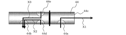
- the rotation stop position of the valve body 44 of the integrated heat medium flow switching device 40 when the indoor unit 3 by the integrated heat medium flow switching device 40 provided in the relay machine 2 in FIG. It is explanatory drawing of the flow of a thermal medium. It is a figure which shows the modification of the integrated heat medium flow-path switching apparatus of embodiment of this invention.
- FIG. 1 is a schematic diagram illustrating an installation example of an air conditioner 100 according to an embodiment of the present invention. Based on FIG. 1, the installation example of the air conditioning apparatus 100 is demonstrated.
- the air conditioner 100 uses each refrigeration cycle (refrigerant circulation circuit A, heat medium circulation circuit B) that circulates the refrigerant (heat source side refrigerant, heat medium) so that each indoor unit can freely perform heating operation or cooling operation. It can be selected.
- FIG. 1 schematically shows the entire air conditioner 100 to which a plurality of indoor units 3 are connected.
- the relationship of the size of each component may be different from the actual one.
- the same reference numerals denote the same or corresponding parts, which are common throughout the entire specification.
- the forms of the constituent elements appearing in the entire specification are merely examples and are not limited to these descriptions.
- an air conditioner 100 includes an outdoor unit (heat source unit) 1, a plurality of indoor units 3, and one unit interposed between the outdoor unit 1 and the indoor unit 3. And a repeater 2.
- the repeater 2 performs heat exchange between the heat source side refrigerant and the heat medium.
- the outdoor unit 1 and the relay unit 2 are connected by a refrigerant pipe 4 through which the heat source side refrigerant passes.
- the repeater 2 and the indoor unit 3 are connected by a pipe (heat medium pipe) 5 through which the heat medium passes.
- the hot or cold heat generated by the outdoor unit 1 is delivered to the indoor unit 3 via the relay unit 2.
- the outdoor unit 1 is usually disposed in an outdoor space 6 that is a space (for example, a rooftop) outside a building 9 such as a building, and supplies hot or cold to the indoor unit 3 via the relay unit 2. .
- the indoor unit 3 is disposed at a position where heating air or cooling air can be supplied to the indoor space 7 which is a space (for example, a living room or the like) inside the building 9, and the heating air is supplied to the indoor space 7 serving as an air-conditioning target space. Alternatively, cooling air is supplied.
- the repeater 2 is configured as a separate housing from the outdoor unit 1 and the indoor unit 3 so that it can be installed at a position different from the outdoor space 6 and the indoor space 7. And the relay machine 2 transmits the heat or cold supplied from the outdoor unit 1 to the indoor unit 3.
- the heat source side refrigerant is conveyed from the outdoor unit 1 to the relay unit 2 through the refrigerant pipe 4.
- the conveyed heat source side refrigerant exchanges heat with the heat medium circulating in the heat medium circuit B in a heat exchanger between heat mediums (described later) in the relay unit 2 to heat or cool the heat medium. That is, hot water or cold water is produced by the heat exchanger between heat media.
- the hot water or cold water produced by the relay machine 2 is conveyed to the indoor unit 3 selected by the heat medium flow switching device (described later) through the heat medium piping 5 by the heat medium conveying device (described later), and the indoor unit 3 Is used for heating operation or cooling operation for the indoor space 7.
- the heat source side refrigerant examples include single refrigerants such as R-22, R-134a, and R32, pseudo-azeotropic mixed refrigerants such as R-410A and R-404A, non-azeotropic mixed refrigerants such as R-407C, and chemical formula
- refrigerants that have a relatively small global warming potential, such as CF 3 CF ⁇ CH 2 , which contains a double bond.
- the heat source side refrigerant may be a mixture of these refrigerants.
- a natural refrigerant such as CO 2 or propane that is in a supercritical state may be used as the heat source side refrigerant.
- the heat medium for example, brine (antifreeze) or water, a mixed solution of brine and water, a mixed solution of water and an additive having a high anticorrosive effect, or the like can be used. Therefore, in the air conditioning apparatus 100, even if the heat medium leaks into the indoor space 7 through the indoor unit 3, it contributes to the improvement of safety because a highly safe heat medium is used. Become.
- an outdoor unit 1 and a relay unit 2 are connected using two refrigerant pipes 4. Further, the relay unit 2 and each indoor unit 3 are connected using two heat medium pipes 5.
- each indoor unit can freely select heating operation or cooling operation (for example, JP-A-5-280818), each unit (outdoor unit 1, indoor unit 3, and relay unit 2). ) Is connected by four pipes.
- the conventional four pipes are used by connecting each unit (the outdoor unit 1, the indoor unit 3, and the relay unit 2) using two pipes. Construction is easier than in the case.
- the repeater 2 is installed in a space such as the back of the ceiling (hereinafter simply referred to as a space 8) that is inside the building 9 but is different from the indoor space 7.
- a space 8 such as the back of the ceiling
- the repeater 2 can also be installed in a common space where there is an elevator or the like.
- the indoor unit 3 is a ceiling cassette type is shown as an example, it is not limited to this and may be a ceiling embedded type or a ceiling suspended type. In short, the indoor unit 3 may be of any type as long as it can blow heating air or cooling air directly into the indoor space 7 or by a duct or the like.
- FIG. 1 shows an example in which the outdoor unit 1 is installed in the outdoor space 6, but the present invention is not limited to this.
- the outdoor unit 1 may be installed in an enclosed space such as a machine room with a ventilation opening. If the waste heat can be exhausted outside the building 9 by an exhaust duct, the outdoor unit 1 may be installed inside the building 9. May be installed. Further, when the outdoor unit 1 is a water-cooled type, it may be installed inside the building 9. Even if the outdoor unit 1 is installed in such a place, no particular problem occurs.
- the repeater 2 can be installed in the vicinity of the outdoor unit 1. However, it should be noted that if the distance from the relay unit 2 to the indoor unit 3 is too long, the power for transporting the heat medium becomes considerably large, so that the energy saving effect is diminished. Furthermore, the number of connected outdoor units 1, indoor units 3, and repeaters 2 is not limited to the number shown in FIG. 1, but depends on the building 9 in which the air conditioner 100 according to the present embodiment is installed. And determine the number.
- the plurality of repeaters 2 When connecting a plurality of repeaters 2 to one outdoor unit, the plurality of repeaters 2 can be installed in a common space in a building such as a building or in a space such as a ceiling. By doing so, an air-conditioning load can be processed with the heat exchanger between heat media in each relay machine 2.
- the indoor unit 3 can be installed at a distance or height within a transfer allowable range of a pump 31 to be described later in each relay unit 2 and can be arranged on the entire building such as a building. .
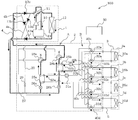
- FIG. 2 is a schematic circuit configuration diagram showing an example of a circuit configuration of the air-conditioning apparatus 100 according to the embodiment of the present invention.
- the structure of the air conditioning apparatus 100 ie, the effect
- the outdoor unit 1 and the relay unit 2 include a heat exchanger related to heat medium (refrigerant-water heat exchanger) 25 a and a heat exchanger related to heat medium (refrigerant—
- the refrigerant pipe 4 is connected via a water heat exchanger 25b.
- relay unit 2 and the indoor unit 3 are connected to the heat exchanger related to heat medium 25a, the heat exchanger related to heat medium 25b, the heat medium flow switching device 32 (32a to 32d), and the heat medium flow switching device 33. They are connected by the heat medium pipe 5 via (33a to 33d).
- the refrigerant pipe 4 and the heat medium pipe 5 will be described in detail later.
- the heat medium flow switching device 32 (32a to 32d) and the heat medium flow switching device 33 (33a to 33d) are shown separately. However, this is for explaining the function of the refrigerant circuit of the air conditioner 100, and structurally, the heat medium flow switching device 32 (32a to 32d) and the heat medium flow switching device 33 (33a to 33d). Is integrated with one integrated heat medium flow switching device 40.
- the number of integrated heat medium flow switching devices 40 is set according to the number of indoor units 3 installed. Here, since four indoor units 3 are provided, four integrated heat mediums are provided. A flow path switching device 40 is mounted. In FIG. 2, the integrated heat medium flow switching device 40a, the integrated heat medium flow switching device 40b, the integrated heat medium flow switching device 40c, and the integrated heat are corresponded to the indoor unit 3 from the upper side of the drawing. This is shown as a medium flow path switching device 40d.
- the present embodiment is characterized by the integrated heat medium flow switching device 40, but details of the integrated heat medium flow switching device 40 will be described in detail later.
- Outdoor unit 1 In the outdoor unit 1, a compressor 10, a first refrigerant flow switching device 11 such as a four-way valve, a heat source side heat exchanger 12, and an accumulator 19 are connected and connected in series through a refrigerant pipe 4. Yes. Further, the outdoor unit 1 is provided with a refrigerant connection pipe 4a, a refrigerant connection pipe 4b, a check valve 13a, a check valve 13b, a check valve 13c, and a check valve 13d. By providing the refrigerant connection pipe 4a, the refrigerant connection pipe 4b, the check valve 13a, the check valve 13b, the check valve 13c, and the check valve 13d, the operation required by the indoor unit 3 can be performed for heating or cooling. Regardless, the flow of the heat-source-side refrigerant that flows into the relay device 2 can be in a certain direction.
- the compressor 10 sucks in the heat source side refrigerant, compresses the heat source side refrigerant to be brought into a high temperature / high pressure state, and conveys it to the refrigerant circulation circuit A. Good.
- the first refrigerant flow switching device 11 has a flow of the heat source side refrigerant in a heating operation (in a heating only operation mode and a heating main operation mode described later) and a cooling operation (in a cooling only operation mode and a cooling main operation described later). In the mode).
- the heat source side heat exchanger 12 functions as an evaporator during heating operation, and functions as a condenser (or radiator) during cooling operation.
- the heat source side heat exchanger 12 exchanges heat between a fluid of air supplied from a blower such as a fan (not shown) and the heat source side refrigerant, and evaporates or condenses the heat source side refrigerant.
- the accumulator 19 is provided on the suction side of the compressor 10 and stores excess refrigerant due to a difference between the heating operation and the cooling operation, or excess refrigerant with respect to a transient change in operation.
- the check valve 13c is provided in the refrigerant pipe 4 between the relay machine 2 and the first refrigerant flow switching device 11, and the heat source side refrigerant is only in a predetermined direction (direction from the relay machine 2 to the outdoor unit 1). It allows flow.
- the check valve 13a is provided in the refrigerant pipe 4 between the heat source side heat exchanger 12 and the relay device 2, and allows the flow of the heat source side refrigerant only in a predetermined direction (direction from the outdoor unit 1 to the relay device 2). It is acceptable.
- the check valve 13d is provided in the refrigerant connection pipe 4a, and causes the heat source side refrigerant discharged from the compressor 10 to flow through the relay unit 2 during the heating operation.
- the check valve 13 b is provided in the refrigerant connection pipe 4 b, and causes the heat source side refrigerant returned from the relay machine 2 to flow to the suction side of the compressor 10 during the heating operation.
- the refrigerant connection pipe 4 a includes a refrigerant pipe 4 between the first refrigerant flow switching device 11 and the check valve 13 c, and a refrigerant pipe 4 between the check valve 13 a and the relay machine 2.
- the refrigerant connection pipe 4b includes a refrigerant pipe 4 between the check valve 13c and the relay 2, and a refrigerant pipe 4 between the heat source side heat exchanger 12 and the check valve 13a.
- FIG. 2 shows an example in which the refrigerant connection pipe 4a, the refrigerant connection pipe 4b, the check valve 13a, the check valve 13b, the check valve 13c, and the check valve 13d are provided.
- the present invention is not limited to this, and these are not necessarily provided.
- Each indoor unit 3 is equipped with a use side heat exchanger 35.
- the use side heat exchanger 35 is connected to the heat medium flow switching device 32 and the heat medium flow switching device 33 of the relay machine 2 by the heat medium pipe 5.
- the use side heat exchanger 35 exchanges heat between air supplied from a blower such as a fan (not shown) and a heat medium, and generates heating air or cooling air to be supplied to the indoor space 7. To do.
- FIG. 2 shows an example in which four indoor units 3 are connected to the relay unit 2, and are illustrated as an indoor unit 3a, an indoor unit 3b, an indoor unit 3c, and an indoor unit 3d from the upper side of the page.
- the use side heat exchanger 35 also has a use side heat exchanger 35a, a use side heat exchanger 35b, a use side heat exchanger 35c, and a use side heat exchanger from the upper side of the drawing. It is illustrated as 35d.
- the number of connected indoor units 3 is not limited to the four shown in FIG.
- the relay machine 2 includes two or more heat exchangers for heat medium 25 (here, two heat exchangers for heat medium 25a and heat exchanger 25b for heat medium) and two expansion devices 26 (26a, 26b), two opening / closing devices (opening / closing device 27, opening / closing device 29), two second refrigerant flow switching devices 28 (28a, 28b), and pumps 31 (31a, 31b) which are two heat medium transfer devices (Hereinafter referred to as a pump) and four integrated heat medium flow switching devices 40 (40a to 40d).
- the two heat exchangers for heat medium 25 are condensers when supplying heat to the indoor unit 3 that is in the heating operation. It functions as a radiator. Further, the two heat exchangers 25 between heat mediums (heat medium heat exchanger 25a, heat medium heat exchanger 25b) evaporate when supplying cold heat to the indoor unit 3 that is performing the cooling operation. It functions as a vessel. The two heat exchangers between heat media 25 exchange heat between the heat source side refrigerant and the heat medium, and transmit the heat or cold generated by the outdoor unit 1 and stored in the heat source side refrigerant to the heat medium. is there.
- the heat exchanger related to heat medium 25a is provided between the expansion device 26a and the second refrigerant flow switching device 28a in the refrigerant circuit A, and serves to cool the heat medium in the cooling / heating mixed operation mode. is there. Further, the heat exchanger related to heat medium 25b is provided between the expansion device 26b and the second refrigerant flow switching device 28b in the refrigerant circulation circuit A, and serves to heat the heat medium in the cooling / heating mixed operation mode. Is.
- the two expansion devices 26 (the expansion device 26a and the expansion device 26b) have a function as a pressure reducing valve or an expansion valve, and expand the heat source side refrigerant by reducing the pressure.
- the expansion device 26a is provided on the upstream side of the heat exchanger related to heat medium 25a in the flow of the heat source side refrigerant during the cooling only operation.
- the expansion device 26b is provided on the upstream side of the heat exchanger related to heat medium 25b in the flow of the heat source side refrigerant during the cooling only operation.
- the two expansion devices 26 may be configured by a device whose opening degree can be variably controlled, for example, an electronic expansion valve.
- the two opening / closing devices are configured by electromagnetic valves or the like that can be opened and closed by energization, and open / close the refrigerant pipe 4. That is, the opening / closing of the two opening / closing devices (opening / closing device 27, opening / closing device 29) is controlled according to the operation mode, and the flow path of the heat source side refrigerant is switched.
- the opening / closing device 27 is provided in the refrigerant pipe 4 (the refrigerant pipe 4 located at the lowest level in FIG. 2 among the refrigerant pipes 4 connecting the outdoor unit 1 and the relay unit 2) on the inlet side of the heat source side refrigerant. ing.
- the opening / closing device 29 is provided in a pipe (bypass pipe 20) connecting the refrigerant pipe 4 on the inlet side of the heat source side refrigerant and the refrigerant pipe 4 on the outlet side.
- the opening / closing device 27 and the opening / closing device 29 may be any devices that can switch the refrigerant flow path.
- an electronic expansion valve or the like that can variably control the opening degree may be used.
- the two second refrigerant flow switching devices 28 are constituted by, for example, a four-way valve or the like, and the heat exchanger related to heat medium according to the operation mode.
- the flow of the heat source side refrigerant is switched so that 25 acts as a condenser or an evaporator.
- the second refrigerant flow switching device 28a is provided on the downstream side of the heat exchanger related to heat medium 25a in the flow of the heat source side refrigerant in the cooling only operation mode.
- the second refrigerant flow switching device 28b is provided on the downstream side of the heat exchanger related to heat medium 25b in the flow of the heat source side refrigerant in the cooling only operation mode.
- the two pumps 31 (pump 31a and pump 31b) circulate the heat medium passing through the heat medium pipe 5 to the heat medium circuit B.
- the pump 31 a is provided in the heat medium pipe 5 between the heat exchanger related to heat medium 25 a and the integrated heat medium flow switching device 40.
- the pump 31 b is provided in the heat medium pipe 5 between the heat exchanger related to heat medium 25 b and the integrated heat medium flow switching device 40.
- the two pumps 31 may be configured with, for example, capacity-controllable pumps, and the flow rate thereof may be adjusted depending on the load in the indoor unit 3.
- the integrated heat medium flow switching device 40 is provided corresponding to each of the indoor units 3, and the connection destination of the corresponding use side heat exchanger 35 is connected to the heat exchanger between heat mediums 25a or 25a. It has a function of switching to the heat exchanger related to heat medium 25b. Specifically, the integrated heat medium flow switching device 40 opens the internal flow path, and switches the heat medium flow path to the heat exchanger related to heat medium 25a or the heat exchanger related to heat medium 25b. The switching of the heat medium flow path includes not only complete switching from one to the other but also partial switching from one to the other.
- the integrated heat medium flow switching device 40 adjusts the flow area of the heat medium to the indoor unit 3 by adjusting the flow rate of the heat medium flowing in the heat medium pipe 5 by adjusting the opening area of the flow path. It also has functions. The integrated heat medium flow switching device 40 adjusts the amount of the heat medium flowing into the indoor unit 3 according to the temperature of the heat medium flowing into the indoor unit 3 and the temperature of the heat medium flowing out to the air conditioning load of the indoor space 7. It is possible to provide the indoor unit 3 with the optimum amount of heat medium.
- the integrated heat medium flow switching device 40 only needs to have at least a flow switching function.
- the integrated heat medium flow switching device 40 will be described as having both a flow switching function and a flow rate adjusting function.
- the integrated heat medium flow path switching device 40 When the indoor unit 3 does not require a load such as stop or thermo OFF, or when it is desired to shut off the heat medium flow path for maintenance or the like, the integrated heat medium flow path switching device 40 is fully closed. Thus, the supply of the heat medium to the indoor unit 3 can be stopped. That is, the integrated heat medium flow switching device 40 also has a function of blocking the internal flow path and disconnecting the corresponding use side heat exchanger 35 from the heat medium circulation circuit B.
- the relay 2 is provided with a temperature sensor 55 (temperature sensor 55a, temperature sensor 55b) for detecting the temperature of the heat medium on the outlet side of the heat exchanger 25 between heat mediums.
- Information (temperature information) detected by the temperature sensor 55 is sent to the control device 50 that performs overall control of the operation of the air conditioner 100.
- the control device 50 is configured by a microcomputer or the like, and controls the entire air conditioner 100 based on detection information from various detection means and instructions from a remote controller. That is, the control device 50 controls the driving frequency of the compressor 10, the rotation speed of the blower (not shown) (including ON / OFF), the switching of the first refrigerant flow switching device 11, the driving frequency of the pump 31, and the second refrigerant flow channel. Switching of the switching device 28, opening of the expansion device 26, opening and closing of the switching devices 27 and 29, control of the driving device 41 of the integrated heat medium flow switching device 40 (switching of the flow path of the heat medium, heat of the indoor unit 3) Control of media flow rate adjustment). Moreover, the control apparatus 50 performs each operation mode mentioned later.
- control device 50 is separately provided from the outdoor unit 1, the indoor unit 3, and the relay unit 2, and the configuration in which communication with these units is provided is illustrated, but the configuration is not limited thereto. .
- it may be installed in any one of the outdoor unit 1, the indoor unit 3, and the relay unit 2, and the function of the control device 50 is distributed and provided in each of the outdoor unit 1, the indoor unit 3, and the relay unit 2. It is also possible to adopt a configuration in which cooperation processing is performed by performing data communication.
- the heat medium pipe 5 through which the heat medium passes is composed of one connected to the heat exchanger related to heat medium 25a and one connected to the heat exchanger related to heat medium 25b.
- the heat medium pipe 5 is branched (here, four branches) in accordance with the number of indoor units 3 connected to the relay unit 2.
- the heat medium pipe 5 is connected to the integrated heat medium flow switching device 40. By controlling the integrated heat medium flow switching device 40, the heat medium from the heat exchanger related to heat medium 25 a flows into the use side heat exchanger 35, or the heat medium from the heat exchanger related to heat medium 25 b is used as the heat medium. Whether to flow into the use side heat exchanger 35 can be switched.
- the compressor 10 In the air conditioner 100, the compressor 10, the first refrigerant flow switching device 11, the heat source side heat exchanger 12, the switching device 27, the switching device 29, the second refrigerant flow switching device 28, and heat exchange between heat media.
- the refrigerant flow path, the expansion device 26 and the accumulator 19 of the container 25 are connected by the refrigerant pipe 4 to constitute the refrigerant circulation circuit A.
- the heat medium flow circuit of the heat exchanger 25 between the heat medium, the pump 31, the integrated heat medium flow switching device 40, and the use side heat exchanger 35 are connected by the heat medium pipe 5 to form a heat medium circulation circuit.
- B is configured. That is, a plurality of use side heat exchangers 35 are connected in parallel to each of the heat exchangers 25 between heat mediums, and the heat medium circulation circuit B has a plurality of systems.
- the heat source side refrigerant circulating in the refrigerant circuit A and the heat medium circulating in the heat medium circuit B exchange heat in the intermediate heat exchanger 25a and the intermediate heat exchanger 25b. It is like that.
- the air conditioning apparatus 100 can realize an optimal heating operation or cooling operation according to the air conditioning load.
- the air conditioner 100 can perform a heating operation or a cooling operation in the indoor unit 3 based on an instruction from each indoor unit 3. That is, the air conditioning apparatus 100 can perform the same operation for all the indoor units 3 and can perform different operations for each of the indoor units 3.
- the operation modes executed by the air conditioner 100 include the following four modes. Hereinafter, each operation mode will be described together with the flow of the heat source side refrigerant and the heat medium.
- Heating operation mode mode in which all of the driven indoor units 3 perform heating operation
- All-cooling operation mode mode in which all driven indoor units 3 perform cooling operation
- Heating-main operation mode cooling and heating mixed operation mode in which the heating load is larger than the cooling load
- Cooling-main operation mode cooling / heating mixed operation mode in which the cooling load is larger than the heating load
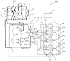
- FIG. 3 is a refrigerant circuit diagram illustrating a refrigerant flow when the air-conditioning apparatus 100 according to the embodiment of the present invention is in the heating only operation mode.
- the heating only operation mode will be described by taking as an example a case where all of the use side heat exchanger 35a to the use side heat exchanger 35d are in a heating operation and a heating load is generated in all.
- the pipes represented by the thick lines indicate the pipes through which the heat source side refrigerant flows.
- the flow direction of the heat source side refrigerant is indicated by a solid line arrow, and the flow direction of the heat medium is indicated by a broken line arrow.
- the first refrigerant flow so that the heat source side refrigerant discharged from the compressor 10 flows into the relay machine 2 without passing through the heat source side heat exchanger 12.
- the path switching device 11 is switched.
- the pump 31a and the pump 31b are driven to open the heat medium flow switching device 32a to the heat medium flow switching device 32d.
- the integrated heat medium flow switching device 40a By opening the integrated heat medium flow switching device 40a to the integrated heat medium flow switching device 40d, each of the intermediate heat exchanger 25a and the intermediate heat exchanger 25b and the use side heat exchanger 35a A heat medium circulates between the use side heat exchanger 35d.
- the second refrigerant flow switching device 28a and the second refrigerant flow switching device 28b are switched to the heating side (solid line side in FIG. 2), the opening / closing device 27 is closed, and the opening / closing device 29 is open. .
- the low-temperature and low-pressure refrigerant is compressed by the compressor 10 and is discharged from the compressor 10 as a high-temperature and high-pressure gas refrigerant.
- the high-temperature and high-pressure gas refrigerant discharged from the compressor 10 passes through the first refrigerant flow switching device 11, passes through the refrigerant connection pipe 4 a and the check valve 13 d, and flows out of the outdoor unit 1.
- the high-temperature and high-pressure gas refrigerant that has flowed out of the outdoor unit 1 flows into the relay unit 2 through the refrigerant pipe 4.
- the high-temperature and high-pressure gas refrigerant that has flowed into the relay unit 2 is branched and passes through the second refrigerant flow switching device 28a and the second refrigerant flow switching device 28b, and the heat exchanger related to heat medium 25a and the heat exchange between heat media. Flows into the vessel 25b.
- the high-temperature and high-pressure gas refrigerant flowing into the heat exchanger related to heat medium 25a and the heat exchanger related to heat medium 25b is condensed and liquefied while dissipating heat to the heat medium circulating in the heat medium circulation circuit B, and becomes a high-pressure liquid refrigerant. It flows out of the heat exchanger related to heat medium 25a and the heat exchanger related to heat medium 25b.
- the liquid refrigerant that has flowed out of the heat exchanger related to heat medium 25a and the heat exchanger related to heat medium 25b is expanded by the expansion device 26a and the expansion device 26b to become a low-temperature / low-pressure two-phase refrigerant. After these two-phase refrigerants merge, they flow out from the relay unit 2 through the opening / closing device 29, and flow into the outdoor unit 1 again through the refrigerant pipe 4.
- the refrigerant that has flowed into the outdoor unit 1 passes through the refrigerant connection pipe 4b and the check valve 13b, and then flows into the heat source side heat exchanger 12 that functions as an evaporator.
- the heat-source-side refrigerant that has flowed into the heat-source-side heat exchanger 12 absorbs heat from the air in the outdoor space 6 (hereinafter referred to as “outside air”) by the heat-source-side heat exchanger 12, and becomes a low-temperature / low-pressure gas refrigerant.
- the low-temperature and low-pressure gas refrigerant flowing out from the heat source side heat exchanger 12 is again sucked into the compressor 10 via the first refrigerant flow switching device 11 and the accumulator 19.
- the expansion device 26 is a value obtained by converting the pressure of the heat-source-side refrigerant flowing between the heat exchanger 25 between the heat medium 25 and the expansion device 26 into a saturation temperature, and the temperature on the outlet side of the heat exchanger 25 between the heat medium.
- the degree of opening is controlled by the control device 50 so that the subcool (degree of supercooling) obtained as a difference from the above becomes constant.
- the temperature of the intermediate position of the heat exchanger 25 between heat media you may use it instead of the saturation temperature which converted the temperature in the intermediate position. In this case, it is not necessary to install a pressure sensor, and the system can be configured at low cost.
- the heat of the heat source side refrigerant is transmitted to the heat medium in both the heat exchanger 25a and the heat exchanger 25b, and the heated heat medium is heated by the pump 31a and the pump 31b.
- the inside of the pipe 5 is allowed to flow.
- the heat medium pressurized by the pump 31a and the pump 31b is switched in flow path by the integrated heat medium flow switching device 40 and flows into the use side heat exchanger 35a to the use side heat exchanger 35d.
- the total heating capacity of the indoor units 3 heated by the heat medium passing through the heat exchanger related to heat medium 25a and the total of the indoor units 3 heated by the heat medium passing through the heat exchanger related to heat medium 25b It is desirable to switch the flow path so that the heating capacity can be divided approximately by half.
- the capacity of each indoor unit 3 to be heated can be determined, for example, by the control device 50, and the flow path of the integrated heat medium flow path switching device 40 is switched according to the heating capacity.
- the heat medium that has passed through the heat exchanger related to heat medium 25a flows into the use-side heat exchangers 35c and 35d, and the heat medium that has passed through the heat exchanger related to heat medium 25b is used as the use-side heat exchanger 35a.
- Each of the integrated heat medium flow switching devices 40 is switched so as to flow into 35b.
- the heat medium flowing into the use side heat exchanger 35a to the use side heat exchanger 35d dissipates heat to the indoor air, thereby heating the indoor space 7.
- the heat medium flows out of the use side heat exchanger 35a to the use side heat exchanger 35d and flows again into the integrated heat medium flow switching device 40a to the integrated heat medium flow switching device 40d.
- the integrated heat medium flow switching device 40 is controlled so that the flow rate of the heat medium becomes a flow rate necessary for processing the air conditioning load required in the room.
- the heat medium having the adjusted flow rate is supplied to the use side heat exchanger 35a to the use side heat exchanger 35d. Inflow.
- the amount of heat radiated to the indoor space 7 is received from the refrigerant side and is sucked into the pump 31a or the pump 31b again.
- the flow rate of the heat medium flowing into the use-side heat exchanger 35 is adjusted. Is as follows. That is, the temperature detected by the temperature sensor 55a or the temperature detected by the temperature sensor 55b and the temperature difference between the temperature of the heat medium flowing out from the use side heat exchanger 35 are integrated so as to be maintained at the target value.
- the opening degree of the heat medium flow switching device 40 is controlled. That is, when the temperature difference is larger than the target value, the integrated heat medium flow switching device 40 is controlled in the direction of narrowing the opening area of the flow path, and when the temperature difference is smaller than the target value, the flow path opening.
- the integrated heat medium flow switching device 40 is controlled in the direction of expanding the area.
- an optimal heat medium flow rate according to the air conditioning load of the indoor space 7 can be flowed to the use side heat exchanger 35, and the air conditioning load is appropriately adjusted. Can be processed.
- the outlet temperature of the heat exchanger related to heat medium 25 either the temperature sensor 55a or the temperature sensor 55b may be used, or the average temperature thereof may be used.
- the opening degree of the integrated heat medium flow switching device 40 is not the temperature difference between the temperature originally detected by the temperature sensors 55a and 55b and the temperature of the heat medium flowing out from the use side heat exchanger 35, but the utilization. It should be controlled by the temperature difference between the inlet and outlet of the side heat exchanger 35.
- the heat medium temperature on the inlet side of the use side heat exchanger 35 is almost the same as the temperature detected by the temperature sensor 55. Therefore, the temperature on the inlet side of the use side heat exchanger 35 can be substituted by the temperature of the temperature sensor 55 at the outlet of the heat exchanger related to heat medium 25 to which the use side heat exchanger 35 is connected.
- the system can be configured at low cost.
- the opening degree of the integrated heat medium flow switching device 40 is controlled by the above temperature difference.
- the integrated heat medium flow path is determined according to the heat medium temperature at the outlet of the heat exchanger related to heat medium 25.
- the opening degree of the switching device 40 may be controlled.
- the opening degree of the integrated heat medium flow switching device 40 may be controlled so that the heat medium temperature at the outlet of the heat exchanger related to heat medium 25 is maintained at the target value.
- the flow path is closed by the integrated heat medium flow switching device 40 so that the heat medium does not flow to the use-side heat exchanger 35.
- the heat medium is flown in all of the use side heat exchanger 35a to the use side heat exchanger 35d because there is a heat load, but when the heat load is lost, the corresponding integrated heat medium flow
- the path switching device 40 may be fully closed. Then, when a thermal load is generated again, the corresponding integrated heat medium flow switching device 40 may be opened to circulate the heat medium. The same applies to other operation modes described below.
- FIG. 4 is a refrigerant circuit diagram illustrating a refrigerant flow when the air-conditioning apparatus 100 is in the cooling only operation mode.
- the cooling only operation mode will be described by taking as an example a case where all of the use side heat exchangers 35a to 35d are in cooling operation and a cooling load is generated in all.
- the flow direction of the heat source side refrigerant is indicated by a solid line arrow, and the flow direction of the heat medium is indicated by a broken line arrow.
- the first refrigerant flow switching device 11 is switched so that the heat source side refrigerant discharged from the compressor 10 flows into the heat source side heat exchanger 12.
- the pump 31a and the pump 31b are driven, and the integrated heat medium flow switching device 40 is opened.
- the integrated heat medium flow switching device 40 By opening the integrated heat medium flow switching device 40, the heat exchanger related to heat medium 25a and the heat exchanger related to heat medium 25b are connected to the use side heat exchanger 35a to the use side heat exchanger 35d.
- the heat medium is circulated.
- the integrated heat medium flow switching device 40 at this time is switched to the cooling side (dotted line side in FIG. 2), the opening / closing device 27 is open, and the opening / closing device 29 is closed.
- the low-temperature and low-pressure refrigerant is compressed by the compressor 10 and is discharged from the compressor 10 as a high-temperature and high-pressure gas refrigerant.
- the high-temperature and high-pressure gas refrigerant discharged from the compressor 10 passes through the first refrigerant flow switching device 11 and flows into the heat source side heat exchanger 12.
- the refrigerant that has flowed into the heat source side heat exchanger 12 exchanges heat with the outside air, becomes a high-temperature and high-pressure liquid or two-phase refrigerant, and flows out of the heat source side heat exchanger 12.
- the refrigerant that has flowed out of the heat source side heat exchanger 12 flows out of the outdoor unit 1 after passing through the check valve 13a.
- the high-temperature / high-pressure liquid or two-phase refrigerant that has flowed out of the outdoor unit 1 flows into the relay unit 2 through the refrigerant pipe 4.
- the high-temperature / high-pressure liquid or the two-phase refrigerant that has flowed into the relay unit 2 passes through the opening / closing device 27 and is branched and expanded by the expansion device 26a and the expansion device 26b to become a low-temperature / low-pressure two-phase refrigerant. .
- These two-phase refrigerants evaporate while absorbing heat from the heat medium circulating in the heat medium circuit B, and become low-temperature gas refrigerants.
- the gas refrigerant that has flowed out of the heat exchanger related to heat medium 25a and the heat exchanger related to heat medium 25b passes through the second refrigerant flow switching device 28a and the second refrigerant flow switching device 28b, and then merges together. Spill from.
- the refrigerant that has flowed out of the relay machine 2 passes through the refrigerant pipe 4 and the check valve 13c, and is again sucked into the compressor 10 via the first refrigerant flow switching device 11 and the accumulator 19.
- the expansion device 26 calculates a value obtained by converting the pressure of the heat-source-side refrigerant flowing between the heat exchanger 25 between the heat medium 25 and the expansion device 26 into a saturation temperature and the temperature on the outlet side of the heat exchanger 25 between the heat media.
- the opening degree is controlled so that the superheat (superheat degree) obtained as the difference becomes constant.
- a saturation temperature obtained by converting the temperature at the intermediate position may be used instead. In this case, it is not necessary to install a pressure sensor, and the system can be configured at low cost.
- the flow of the heat medium in the heat medium circuit B will be described.
- the cold heat of the heat medium is transmitted to the heat source side refrigerant in both the heat exchangers 25a and 25b, and the cooled heat medium is heated by the pump 31a and the pump 31b.
- the inside of the pipe 5 is allowed to flow.
- the heat medium pressurized by the pump 31a and the pump 31b is switched by the integrated heat medium flow switching device 40 and flows into the use side heat exchanger 35a to the use side heat exchanger 35d.
- the total cooling capacity of the indoor unit 3 that cools the heat medium that has passed through the heat exchanger related to heat medium 25a, and the total of the indoor unit 3 that cools the heat medium that has passed through the heat exchanger related to heat medium 25b It is desirable to switch the flow path so that the cooling capacity can be divided approximately in half.
- each indoor unit 3 to be cooled can be determined by the control device 50, for example, and the flow path of the integrated heat medium flow path switching device 40 is switched according to the cooling capacity.
- the heat medium that has passed through the heat exchanger related to heat medium 25a flows into the use-side heat exchangers 35c and 35d, and the heat medium that has passed through the heat exchanger related to heat medium 25b is used as the use-side heat exchanger 35a.
- Each of the integrated heat medium flow switching devices 40 is switched so as to flow into 35b.
- the heat medium that has flowed into the use side heat exchanger 35a to the use side heat exchanger 35d absorbs heat from the indoor air, thereby cooling the indoor space 7.
- the heat medium flows out of the use side heat exchanger 35a to the use side heat exchanger 35d and flows again into the integrated heat medium flow switching device 40a to the integrated heat medium flow switching device 40d.
- the integrated heat medium flow switching device 40 to the integrated heat medium flow switching device 40d are controlled so that the flow rate of the heat medium becomes a flow rate necessary for processing the air conditioning load of the indoor space 7.
- the heat medium having the adjusted flow rate is supplied to the use side heat exchanger 35a to the use side heat exchanger 35d. Inflow.
- the amount of heat absorbed from the indoor space 7 is passed to the refrigerant side and is sucked into the pump 31a or the pump 31b again.
- the flow rate of the heat medium flowing into the use-side heat exchanger 35 is adjusted. Is as follows. That is, the temperature detected by the temperature sensor 55a or the temperature detected by the temperature sensor 55b and the temperature difference between the temperature of the heat medium flowing out from the use side heat exchanger 35 are integrated so as to be maintained at the target value.
- the opening degree of the heat medium flow switching device 40 is controlled. That is, when the temperature difference is larger than the target value, the integrated heat medium flow switching device 40 is controlled in the direction of narrowing the opening area of the flow path, and when the temperature difference is smaller than the target value, the flow path opening.
- the integrated heat medium flow switching device 40 is controlled in the direction of expanding the area.
- an optimal heat medium flow rate according to the air conditioning load of the indoor space 7 can be flowed to the use side heat exchanger 35, and the air conditioning load is appropriately adjusted. Can be processed.
- the outlet temperature of the heat exchanger related to heat medium 25 either the temperature sensor 55a or the temperature sensor 55b may be used, or the average temperature thereof may be used.
- the opening degree of the integrated heat medium flow switching device 40 is not the temperature difference between the temperature originally detected by the temperature sensors 55a and 55b and the temperature of the heat medium flowing out from the use side heat exchanger 35, but the utilization. It should be controlled by the temperature difference between the inlet and outlet of the side heat exchanger 35.
- the heat medium temperature on the inlet side of the use side heat exchanger 35 is almost the same as the temperature detected by the temperature sensor 55. Therefore, the temperature on the inlet side of the use side heat exchanger 35 can be substituted by the temperature of the temperature sensor 55 at the outlet of the heat exchanger related to heat medium 25 to which the use side heat exchanger 35 is connected.
- the system can be configured at low cost.
- the opening of the integrated heat medium flow switching device 40 is controlled based on the above temperature difference, but the integrated heat medium flow path depends on the heat medium temperature at the outlet of the heat exchanger related to heat medium 25.
- the opening degree of the switching device 40 may be controlled.
- the opening degree of the integrated heat medium flow switching device 40 may be controlled so that the heat medium temperature at the outlet of the heat exchanger related to heat medium 25 is maintained at the target value.
- FIG. 5 is a refrigerant circuit diagram illustrating a refrigerant flow in the heating main operation mode of the air-conditioning apparatus 100 according to the embodiment of the present invention.
- a pipe indicated by a bold line indicates a pipe through which the heat source side refrigerant circulates.
- the flow direction of the heat source side refrigerant is indicated by a solid line arrow, and the flow direction of the heat medium is indicated by a broken line arrow.
- both the expansion device 26a and the expansion device 26b function as expansion valves.
- one of the expansion devices 26a and 26b is fully opened and the other functions as an expansion valve.
- both the heat exchanger 25a and the heat exchanger 25b function as a condenser
- the heat exchanger 25b The condenser and the heat exchanger related to heat medium 25a function as an evaporator.
- the first refrigerant flow is performed so that the heat source side refrigerant discharged from the compressor 10 flows into the relay machine 2 without passing through the heat source side heat exchanger 12.
- the path switching device 11 is switched.
- the pump 31a and the pump 31b are driven to open the integrated heat medium flow switching devices 40a to 40d.
- the heat medium circulates between the heat exchanger related to heat medium 25a and the use side heat exchanger 35 where the cooling load is generated. Further, the heat medium circulates between the heat exchanger related to heat medium 25b and the use side heat exchanger 35 where the heat load is generated.
- the second refrigerant flow switching device 28a is switched to the cooling side (dotted line side in FIG. 2), and the second refrigerant flow switching device 28b is switched to the heating side (solid line side in FIG. 2).
- the expansion device 26a is fully open, the opening / closing device 27 is closed, and the opening / closing device 29 is closed.
- the flow of the heat source side refrigerant in the refrigerant circulation circuit A in the heating main operation mode is the same as the flow of the heat source side refrigerant in the refrigerant circulation circuit A in the heating only operation mode. That is, a low temperature / low pressure refrigerant is compressed by the compressor 10 and discharged as a high temperature / high pressure gas refrigerant.
- the high-temperature and high-pressure gas refrigerant discharged from the compressor 10 passes through the first refrigerant flow switching device 11, passes through the refrigerant connection pipe 4 a and the check valve 13 d, and flows out of the outdoor unit 1.
- the high-temperature and high-pressure gas refrigerant that has flowed out of the outdoor unit 1 flows into the relay unit 2 through the refrigerant pipe 4.
- the high-temperature and high-pressure gas refrigerant that has flowed into the relay machine 2 flows into the heat exchanger related to heat medium 25b that acts as a condenser through the second refrigerant flow switching device 28b.
- the gas refrigerant flowing into the heat exchanger related to heat medium 25b is condensed and liquefied while dissipating heat to the heat medium circulating in the heat medium circuit B, and becomes liquid refrigerant.
- the liquid refrigerant flowing out of the heat exchanger related to heat medium 25b is expanded by the expansion device 26b and becomes a low-pressure two-phase refrigerant.
- This low-pressure two-phase refrigerant flows into the heat exchanger related to heat medium 25a acting as an evaporator via the fully-open expansion device 26a.
- the low-pressure two-phase refrigerant that has flowed into the heat exchanger related to heat medium 25a evaporates by absorbing heat from the heat medium circulating in the heat medium circuit B, thereby cooling the heat medium.
- the low-pressure two-phase refrigerant flows out of the heat exchanger related to heat medium 25a, flows out of the relay unit 2 through the second refrigerant flow switching device 28a, and flows into the outdoor unit 1 again through the ref
- the low-temperature and low-pressure two-phase refrigerant that has flowed into the outdoor unit 1 flows into the heat source side heat exchanger 12 that acts as an evaporator through the check valve 13b.
- coolant which flowed into the heat source side heat exchanger 12 absorbs heat from external air in the heat source side heat exchanger 12, and turns into a low temperature and low pressure gas refrigerant.
- the low-temperature and low-pressure gas refrigerant flowing out from the heat source side heat exchanger 12 is again sucked into the compressor 10 via the first refrigerant flow switching device 11 and the accumulator 19.
- the opening degree of the expansion device 26b is controlled so that the subcooling (supercooling degree) of the outlet refrigerant of the heat exchanger related to heat medium 25b becomes a target value.
- the expansion device 26b may be fully opened, and the subcool may be controlled by the expansion device 26a.
- the heat of the heat source side refrigerant is transmitted to the heat medium in the heat exchanger related to heat medium 25b, and the heated heat medium is caused to flow in the heat medium pipe 5 by the pump 31b.
- the cold heat of the heat source side refrigerant is transmitted to the heat medium by the heat exchanger related to heat medium 25a, and the cooled heat medium is caused to flow in the heat medium pipe 5 by the pump 31a.
- the heated heat medium pressurized and discharged by the pump 31b flows into the use side heat exchanger 35 where the heat load is generated via the integrated heat medium flow switching device 40.
- the cooled heat medium that has flowed out after being pressurized by the pump 31a flows into the use side heat exchanger 35 where the cold load is generated via the integrated heat medium flow switching device 40.
- the integrated heat medium flow switching device 40 performs heat exchange between heat media in which the connected indoor unit 3 acts as a condenser. It is switched so as to form a heat medium circulation circuit B between the vessel 25b and the pump 31b. Moreover, when the connected indoor unit 3 is in the cooling operation, the integrated heat medium flow switching device 40 is a heat exchanger between heat media in which the connected indoor unit 3 acts as an evaporator. 25a and the pump 31a are switched to form a heat medium circulation circuit B. That is, the integrated heat medium flow switching device 40 can switch the heat medium supplied to the indoor unit 3 to the heating heat medium or the cooling heat medium.
- the cooling operation of the indoor space 7 by the heat medium absorbing heat from the indoor air or the heating operation of the indoor space 7 by the heat medium radiating heat to the indoor air is performed.
- the flow rate of the heat medium is controlled to a flow rate necessary for processing the air conditioning load in the room and flows into the use side heat exchanger 35. Yes.
- the heat medium that has been used for the heating operation and has passed through the use-side heat exchanger 35 and has been slightly lowered in temperature passes through the integrated heat medium flow switching device 40 and flows into the heat exchanger related to heat medium 25b.
- the heat medium that has flowed into the heat exchanger related to heat medium 25b is heated by exchanging heat with the heat source side refrigerant, and then sucked into the pump 31b again.
- the heat medium that has been used for the cooling operation and has passed through the use-side heat exchanger 35 and has slightly increased in temperature passes through the integrated heat medium flow switching device 40 and flows into the heat exchanger related to heat medium 25a.
- the heat medium flowing into the heat exchanger related to heat medium 25a is cooled by exchanging heat with the heat source side refrigerant and then sucked into the pump 31a again.
- the heat medium warmed by the heat exchanger related to heat medium 25b and the heat medium cooled by the heat exchanger related to heat medium 25a are mixed in the relay 2 by the action of the integrated heat medium flow switching device 40. Without being introduced, they are introduced into the use side heat exchanger 35 having a heat load and a heat load, respectively.
- the flow rate of the heat medium flowing into the use-side heat exchanger 35 is adjusted. Is as follows. That is, on the heating side, the integrated heat medium flow switching device 40 so that the temperature difference between the temperature detected by the temperature sensor 55b and the temperature of the heat medium flowing out from the use side heat exchanger 35 is maintained at the target value. Is controlling. Further, on the cooling side, the integrated heat medium flow switching device 40 so that the temperature difference between the temperature of the heat medium flowing out from the use side heat exchanger 35 and the temperature detected by the temperature sensor 55a is maintained at the target value. Is controlling. Thus, by controlling the integrated heat medium flow switching device 40 and adjusting the flow rate of the heat medium flowing into the use-side heat exchanger 35, the air conditioning load in the indoor space 7 can be appropriately processed.
- Cooling operation mode Cooling operation
- FIG. 6 is a refrigerant circuit diagram showing a refrigerant flow in the cooling main operation mode of the air-conditioning apparatus 100 according to the embodiment of the present invention.
- a pipe indicated by a thick line indicates a pipe through which the heat source side refrigerant circulates.
- the flow direction of the heat source side refrigerant is indicated by solid line arrows, and the flow direction of the heat medium is indicated by broken line arrows.
- both the expansion device 26a and the expansion device 26b function as expansion valves.
- one of the expansion devices 26a and 26b is fully opened and the other functions as an expansion valve.
- both the heat exchanger related to heat medium 25a and the heat exchanger related to heat medium 25b function as evaporators, whereas in the cooling main operation, the heat medium is similar to the heating main operation.
- the intermediate heat exchanger 25b functions as a condenser, and the intermediate heat exchanger 25a functions as an evaporator.
- the outdoor unit 1 switches the first refrigerant flow switching device 11 so that the heat source side refrigerant discharged from the compressor 10 flows into the heat source side heat exchanger 12.
- the pump 31a and the pump 31b are driven, and the integrated heat medium flow switching device 40 is opened.
- the heat medium circulates between the heat exchanger related to heat medium 25a and the use side heat exchanger 35 where the heat load is generated.
- the heat medium circulates between the heat exchanger related to heat medium 25b and the use side heat exchanger 35 where the cooling load is generated.
- the second refrigerant flow switching device 28a is switched to the cooling side (dotted line in FIG. 2), and the second refrigerant flow switching device 28b is switched to the heating side (solid line side in FIG. 2).
- the expansion device 26b is fully open, the opening / closing device 27 is closed, and the opening / closing device 29 is closed.
- the flow of the heat source side refrigerant in the refrigerant circulation circuit A in the cooling main operation mode is the same as the flow of the heat source side refrigerant in the refrigerant circulation circuit A in the all cooling operation mode. Further, the flow of the heat medium in the heat medium circuit B in the cooling main operation mode is the same as the flow of the heat medium in the heat medium circuit B in the heating main operation.
- the integrated heat medium flow switching device 40 adjusts the flow rate of the heat medium flowing into the use-side heat exchanger 35 as described above. Specifically, the control is performed as follows. That is, on the cooling side, the integrated heat medium flow switching device 40 so that the temperature difference between the temperature of the heat medium flowing out from the use side heat exchanger 35 and the temperature detected by the temperature sensor 55b is maintained at the target value. Is controlling. On the heating side, the integrated heat medium flow switching device 40 is maintained so that the temperature difference between the temperature detected by the temperature sensor 55a and the temperature of the heat medium flowing out from the use side heat exchanger 35 is maintained at a target value. Is controlling. Thus, by controlling the integrated heat medium flow switching device 40 and adjusting the flow rate of the heat medium flowing into the use-side heat exchanger 35, the air conditioning load in the indoor space 7 can be appropriately processed.
- FIG. 7 is an explanatory diagram of the integrated heat medium flow switching device 40 provided in the repeater 2 of FIG.
- FIG. 7A shows four integrated heat medium flow switching devices 40 (40a to 40d).
- the integrated heat medium flow switching device 40, the heat exchangers between heat media 25, and the indoor unit 3 are shown in FIG. It is a conceptual perspective view of a connection structure with each.
- FIG. 7B shows a longitudinal sectional view of the integrated heat medium flow switching device 40.
- FIG. 8 is a conceptual diagram showing the configuration of the valve body 44 of FIG.
- the integrated heat medium flow switching device 40 includes a body 60, a pair of heat medium transport main pipes 42a and 42b, a pair of heat medium transport main pipes 43a and 43b, and a single valve body 44 configured in an axial shape.
- An indoor unit forward piping 45 and an indoor unit return piping 46 are provided.
- the body 60 is made of PPS or resin. However, as long as the heat capacity of the heat medium is not significantly lost due to heat conduction and heat dissipation to the body 60, other heat capacity can be applied.
- a pair of heat medium transport main tubes 42a and 42b and a pair of heat medium transport main tubes 43a and 43b are opposed to each other with a valve body 44 (described later) interposed therebetween. It has been.
- the pair of heat medium transport main pipes 42a and 42b are connected to the heat exchanger related to heat medium 25a by piping (not shown), and the pair of heat medium transport main pipes 43a and 43b are connected to the heat exchanger related to heat medium 25b via pipes (not shown).
- the body 60 is formed with a pair of heat medium transfer main pipes 42a and 42b and a pair of heat medium transfer main pipes 43a and 43b.
- the valve body 44 is pivoted in the valve chamber 60a. It is arranged so that it can rotate.
- the valve body 44 is rotationally driven by the drive device 41.
- an indoor unit forward piping 45 is connected to an indoor unit side inlet opening 44c described later of the valve body 44.
- the indoor unit return pipe 46 is connected to the body 60, and the end of the indoor unit return pipe 46 opens into the valve chamber 60a.
- the valve body 44 is provided at a pair of selection side openings 44a and 44b that are spaced apart from each other in the axial direction on the outer peripheral surface, and at the end in the axial direction. 35, an indoor unit side inlet opening 44c connected to the inlet side.
- the valve body 44 further includes two indoor unit side outlet openings 44d and 44e provided at positions facing each other on the outer peripheral surface.
- the pair of selection side openings 44a and 44b communicate with the pair of heat medium transport main tubes 42a and 42b or the pair of heat medium transport main tubes 43a and 43b depending on the rotation stop position of the valve body 44.
- the indoor unit side outlet opening 44d is provided in the valve body 44 so as to communicate with the indoor unit return pipe 46 when the pair of selection side openings 44a and 44b communicate with the pair of heat medium transfer main pipes 42a and 42b.
- the indoor unit side outlet opening 44e is provided in the valve body 44 so as to communicate with the indoor unit return pipe 46 when the pair of selection side openings 44a and 44b communicate with the pair of heat medium transfer main pipes 43a and 43b. ing.
- the valve body 44 is provided at a pair of selection side openings 44a and 44b that are spaced apart from each other in the axial direction on the outer peripheral surface, and at the end in the axial direction. 35, an indoor unit side inlet opening 44c connected to the inlet side.
- the valve body 44 further includes two indoor unit side outlet openings 44d and 44e provided at positions facing each other on the outer peripheral surface.
- the indoor unit side outlet opening 44d is provided in the valve body 44 so as to communicate with the indoor unit return pipe 46 when the pair of selection side openings 44a and 44b communicate with the pair of heat medium transfer main pipes 42a and 42b.
- the indoor unit side outlet opening 44e is provided in the valve body 44 so as to communicate with the indoor unit return pipe 46 when the pair of selection side openings 44a and 44b communicate with the pair of heat medium transfer main pipes 43a and 43b. ing.
- the forward flow path X1 is a flow path in which the selection side opening 44a and the indoor unit side inlet opening 44c communicate with each other.
- the return selection flow path X2 is a flow path in which the forward flow path X1, the indoor unit side outlet opening 44d, and the selection side opening 44b communicate with each other.
- the return selection channel X3 is a channel in which the indoor unit side outlet opening 44e and the selection side opening 44b communicate with each other.
- a heat insulating wall 61 is provided between the forward flow path X1 and the return selection flow paths X2 and X3 so that the heat medium passing through the flow paths does not exchange heat capacity. Is provided. Although the heat insulating wall 61 is provided on the valve body 44 here, the structure is not limited as long as the heat capacity is not transferred between the two heat media.
- the pair of selection side openings 44a and 44b are turned into a pair of heat medium transport main tubes 42a and 42b or It connects to a pair of heat carrier conveyance main pipes 43a and 43b.
- the heat medium flow path is switched to the heat medium transport main pipes 42a and 42b or the heat medium transport main pipes 43a and 43b. That is, the connection destination of the indoor unit 3 can be switched to the heat exchanger related to heat medium 25a or the heat exchanger related to heat medium 25b.
- the integrated heat medium flow switching device 40 has a structure in which the heat medium flow switching devices 32 and 33 are integrated by integrating the respective valve bodies of the heat medium flow switching devices 32 and 33. ing.
- each of the heat medium flow switching devices 32 and 33 is configured.
- the valve body was integrated.
- the two driving devices required for driving the two valve bodies can be replaced with a single common driving device 41.
- space saving can be improved, and driving power can be reduced to improve energy saving.
- openings (a pair of selection side openings 44 a and 44 b and an indoor unit side outlet) provided on the outer peripheral surface of the valve body 44 in accordance with the rotation stop position of the valve body 44.
- the opening area (communication area) between the openings 44d and 44e) and the heat medium transport main pipe 42 or the heat medium transport main pipe 43 changes.
- the flow rate of the heat medium can be adjusted by enabling the drive device 41 to adjust the rotation stop position of the valve body 44 such as a stepping motor.
- a device that can be switched (such as an ON / OFF power supply) may be used. .
- the integrated heat medium flow switching device 40 can adjust the flow path and the flow rate according to the rotation stop position of the valve body 44.
- one integrated heat medium flow switching device 40 is provided for each of the plurality of indoor units 3, and all the integrated heat medium flow devices provided in the relay unit 2 are provided.
- the path switching device 40 may be configured integrally. That is, first, the body 60 part of all the integrated heat medium flow switching devices 40 is integrally configured with a common body. Further, each of the heat medium transport main pipe 42 and the heat medium transport main pipe 43 of all the integrated heat medium flow switching devices 40 is a single pipe common to all the integrated heat medium flow switching devices 40. . Thereby, all (here four) integrated heat-medium flow-path switching apparatuses 40 can be comprised integrally. In addition, you may make it integrate not only the structure which integrates all the integrated heat-medium flow-path switching apparatuses 40 but some integrated heat-medium flow-path switching apparatuses 40. FIG.
- the integrated heat medium flow switching device 40 may be separated for each indoor unit 3, and the adjacent integrated heat medium flow switching devices 40 may be connected to each other.
- FIG. 9 shows the valve body 44 of the integrated heat medium flow switching device 40 in a state where the integrated heat medium flow switching device 40 provided in the relay machine 2 of FIG. 1 is switched to the heat exchanger related to heat medium 25a. It is explanatory drawing of the rotation stop position and the flow of a heat medium.
- FIG. 9A shows four integrated heat medium flow switching devices 40a to 40d
- FIG. 9B shows a longitudinal sectional view of the integrated heat medium flow switching device 40. .
- the flow direction of the heat medium is indicated by solid arrows.
- the valve body 44 When the integrated heat medium flow switching device 40 is switched to the heat exchanger related to heat medium 25a, the valve body 44 is rotated by the drive device 41, and the internal flow path of the valve body 44 is shown in FIG. In this way, the heat medium conveyance main pipes 42a and 42b are communicated with each other. That is, the pair of selection side openings 44 a and 44 b are communicated with the pair of heat medium transfer main pipes 42 a and 42 b, and the indoor unit side outlet opening 44 d is communicated with the indoor unit return pipe 46.
- the heat medium pressurized and discharged by the pump 31 flows into the heat medium transport main pipe 42a (arrow a1).
- the heat medium flowing into the heat medium transport main pipe 42a passes through the forward flow path X1 and is transported to the connection indoor unit 3 (arrow a2).
- the heat medium that has been transferred to the connection indoor unit 3 and has exchanged heat with the indoor space 7 in the use side heat exchanger 35 in the connection indoor unit 3 flows into the integrated heat medium flow switching device 40 again. . That is, the heat medium flowing into the integrated heat medium flow switching device 40 first flows into the indoor unit return pipe 46 (arrow a3), passes through the return selection flow path X2, and flows into the heat medium transport main pipe 42b. (Arrow a4).
- the heat medium that has passed through the heat medium transport main pipe 42b flows out of the integrated heat medium flow switching device 40 and flows again into the heat exchanger related to heat medium 25a (arrow a5).
- the heat medium circulation circuit B that connects the heat exchanger related to heat medium 25 a and the indoor unit 3 is formed by switching the rotation stop position of the valve body 44 of the integrated heat medium flow switching device 40.
- valve body 44 returns to the integrated heat medium flow switching device 40 from the heat transfer medium main pipe 42a to the connection indoor unit 3 through the forward flow path X1 and from the connection indoor unit 3 to the integrated heat medium flow switching device 40. Then, the heat medium passing through the return selection flow path X2 passes. Although there is a temperature difference between the two heat media, the heat insulating wall 61 suppresses transfer of heat capacity between the two heat media.
- the above is the rotation stop position of the valve body 44 and the flow of the heat medium inside the valve body 44 when the integrated heat medium flow switching device 40 is switched to the inter-heat medium heat exchanger 25a side.
- the integrated heat medium flow switching device 40 also adjusts the flow rate of the heat medium flowing through the connection indoor unit 3 as described above, in addition to the flow path switching.
- adjusting the flow rate of the heat medium it is adjusted by controlling the rotation stop position of the valve element 44 by the driving device 41.
- the rotation stop position of the valve body 44 is controlled so that the opening area of the communication portion between the pair of heat medium transfer main pipes 42a and 42b and the pair of selection side openings 44a and 44b is increased. To do.
- the rotation stop position of the valve body 44 is reduced so that the opening area of the communication portion between the pair of heat medium transfer main tubes 42a and 42b and the pair of selection side openings 44a and 44b is reduced. To control.
- FIG. 10 shows the rotation stop position of the integrated heat medium flow switching device 40 in a state in which the integrated heat medium flow switching device 40 provided in the relay machine 2 of FIG. 1 is switched to the heat exchanger related to heat medium 25b. It is explanatory drawing of the flow of a heat carrier.
- FIG. 10A shows four integrated heat medium flow switching devices 40a to 40d
- FIG. 10B shows a longitudinal sectional view of the integrated heat medium flow switching device 40. .
- the flow direction of the heat medium is indicated by solid arrows.
- the valve body 44 When switching the integrated heat medium flow switching device 40 to the heat exchanger related to heat medium 25a, the valve body 44 is rotated by the drive device 41, and the flow path of the valve body 44 is paired as shown in FIG.
- the heat medium conveyance main pipes 43a and 43b communicate with each other. That is, the pair of selection side openings 44 a and 44 b are communicated with the pair of heat medium transfer main pipes 43 a and 43 b, and the indoor unit side outlet opening 44 e is communicated with the indoor unit return pipe 46.
- the heat medium pressurized and discharged by the pump 31 flows into the heat medium transport main pipe 43a (arrow a1).
- the heat medium flowing into the heat medium transport main pipe 43a passes through the forward flow path X1 and is transported to the connection indoor unit 3 (arrow a2).
- the heat medium that has been transferred to the connection indoor unit 3 and has exchanged heat with the indoor space 7 in the use side heat exchanger 35 in the connection indoor unit 3 flows into the integrated heat medium flow switching device 40 again. . That is, the heat medium flowing into the integrated heat medium flow switching device 40 first flows into the indoor unit return pipe 46 (arrow a3), passes through the return selection flow path X3, and flows into the heat medium transport main pipe 43b. (Arrow a4).
- the heat medium that has passed through the heat medium transport main pipe 43b flows out of the integrated heat medium flow switching device 40 and flows into the heat exchanger related to heat medium 25b again (arrow a5).
- the heat medium circulation circuit B that connects the heat exchanger related to heat medium 25 b and the indoor unit 3 is formed by switching the rotation stop position of the valve body 44 of the integrated heat medium flow switching device 40.
- valve body 44 returns to the integrated heat medium flow switching device 40 from the heat transfer medium main pipe 43a to the connection indoor unit 3 through the forward flow path X1 and from the connection indoor unit 3 to the integrated heat medium flow switching device 40. And the heat medium passing through the selected flow path X3 passes. Although there is a temperature difference between the two heat media, the heat insulating wall 61 suppresses transfer of heat capacity between the two heat media.
- the above is the rotation stop position of the valve body 44 and the flow of the heat medium inside the valve body 44 when the integrated heat medium flow switching device 40 is switched to the heat exchanger related to heat medium 25b.
- the integrated heat medium flow switching device 40 also adjusts the flow rate of the heat medium flowing through the connection indoor unit 3 as described above, in addition to the flow path switching.
- adjusting the flow rate of the heat medium it is adjusted by controlling the rotational position of the valve body 44 by the driving device 41.
- the rotation stop position of the valve body 44 is controlled so that the opening area of the communication portion between the pair of heat medium transfer main pipes 43a and 43b and the pair of selection side openings 44a and 44b is increased. To do.
- the rotation stop position of the valve body 44 is reduced so that the opening area of the communication portion between the pair of heat medium transfer main tubes 43a and 43b and the pair of selection side openings 44a and 44b is reduced. To control.
- the heat exchanger related to heat medium 25b functions as a condenser and communicates with the heat exchanger related to heat medium 25b as shown in FIG.
- the heating heat medium flows through the pair of heat medium transport main pipes 43a and 43b.
- the heat exchanger related to heat medium 25a functions as an evaporator, and the cooling heat medium flows through the pair of heat medium transfer main tubes 42a and 42b communicating with the heat exchanger related to heat medium 25a.
- the control device 50 drives the drive device 41 to change the valve body 44 of the integrated heat medium flow switching device 40d as shown in FIG.
- the state is rotated to the state shown in FIG.
- the cooling heat medium having a temperature corresponding to the cooling operation flowing through the pair of heat medium transfer main pipes 42a and 42b can be transferred to the indoor unit 3d.
- FIG. 11 shows the rotation stop position of the integrated heat medium flow switching device 40 when the indoor unit 3 is disconnected from the heat medium circulation circuit B by the integrated heat medium flow switching device 40 provided in the repeater 2 of FIG. It is explanatory drawing of the flow of a heat carrier.
- FIG. 11A shows four integrated heat medium flow switching devices 40a to 40d
- FIG. 11B shows a longitudinal sectional view of the integrated heat medium flow switching device 40.
- the flow direction of the heat medium is shown with the solid line arrow.
- the valve body 44 When disconnecting the indoor unit 3 from the heat medium circulation circuit B, the valve body 44 is rotated by the driving device 41 and stopped at the position shown in FIG. That is, the pair of selection side openings 44a and 44b and the indoor unit side outlet opening 44d are provided in any of the pair of heat medium transport main pipes 42a and 42b, the pair of heat medium transport main pipes 43a and 43b, and the indoor unit return pipe 46. Stop at a position that does not communicate. That is, the rotation stop position of the valve body 44 is adjusted to a position where the opening degree becomes zero. Thereby, the flow path between the relay unit 2 and the indoor unit 3 is blocked, and the indoor unit 3 can be disconnected from the heat medium circulation circuit B.
- the integrated heat medium flow switching device 40 is provided corresponding to each of the indoor units 3, the flow of the heat medium to the indoor unit 3 is selected for each indoor unit 3 individually. it can. Therefore, even if some of the four indoor units 3 are in the heating or cooling operation, the inflow of the heat medium can be avoided for the other stopped indoor units 3.
- the indoor unit 3 can be separated from the heat medium circuit B in this way, the following effects can also be achieved. That is, when exchanging and maintaining the components in the heat medium circuit B in the relay unit 2, the indoor unit 3 is disconnected from the heat medium circuit B so that it is discharged from the heat medium circuit B during work. It is possible to minimize the amount of heat medium to be applied. Therefore, work efficiency can be improved, for example, the trouble of refilling the heat medium can be saved. Further, this effect can be similarly achieved when one or more of the plurality of indoor units 3 connected to the relay unit 2 are exchanged.
- the drive devices that are separately required for each of the valve bodies are integrated.
- valve body 44 has a shaft shape, and the internal flow path of the valve body 44 communicates with the pair of heat medium transport main tubes 42a and 42b or the pair of heat medium transport main tubes 43a and 43b according to the rotation stop position of the valve body 44.
- the structure With this structure, an integrated heat medium flow switching device 40 in which the heat medium flow switching device 32 and the heat medium flow switching device 33 are integrated can be configured.
- a pair of selection side openings 44a and 44b are provided on the outer peripheral surface of the valve body 44, and communicate with the pair of heat medium transport main pipes 42a and 42b or the pair of heat medium transport main pipes 43a and 43b depending on the rotational position of the valve body 44.
- the communication area to be changed was changed.
- the integrated heat medium flow switching device 40 can adjust the flow rate of the heat medium flowing in the use side heat exchanger 35. Therefore, the functions of both the flow path switching and the flow rate adjustment can be performed simultaneously by the operation of one driving device 41. For this reason, even if the number of connected indoor units 3 increases, a minimum number of drive devices 41 can be mounted, and energy saving and space saving can be achieved.
- valve body 44 is stopped at a rotation stop position where the selection side openings 44a and 44b of the valve body 44 do not communicate with either the pair of heat medium transport main tubes 42a and 42b and the pair of heat medium transport main tubes 43a and 43b.
- the flow path between the relay unit 2 and the indoor unit 3 can be blocked.
- the indoor unit 3 can be separated from the heat medium circulation circuit B, and therefore, the heat medium discharge amount can be reduced and the maintenance work can be simplified for the following reasons. .
- the indoor unit 3 is disconnected from the heat medium circuit B at the time of maintenance of the heat medium circuit B.
- the heat medium circulation circuit components in the relay unit 2 can be replaced while the heat medium is held in the use side heat exchanger 35 and the heat medium pipe 5. Therefore, the heat medium discharge amount at the time of parts replacement or maintenance can be reduced, and the maintenance work can be simplified. As a result, system maintainability can be improved.
- the number of heat medium flow switching devices can be substantially reduced as described above, the number of maintenance such as replacement of parts can be reduced, and convenience for system use can be reduced. It can be improved.
- the integrated heat medium flow switching device 40 closes the flow path from the relay unit 2 to the indoor unit 3 so that the heat medium is not conveyed to the indoor unit 3 that has been stopped, so that the heat medium
- the conveyance power of the pump 31 that is a conveyance device can be reduced, and the workability can be improved.
- the air conditioner 100 includes the accumulator 19
- the accumulator 19 may not be provided.
- a fan is attached to the heat source side heat exchanger 12 and the use side heat exchanger 35, and in many cases, condensation or evaporation is promoted by blowing air, but this is not restrictive.
- the use side heat exchanger 35 can be a panel heater using radiation
- the heat source side heat exchanger 12 is a water-cooled type that moves heat by water or antifreeze.
- the case where there are four usage-side heat exchangers 35 has been described as an example, but the number is not particularly limited.
- the case where the number of heat exchangers between heat mediums 25a and the heat exchangers between heat mediums 25b is two has been described as an example, naturally, the present invention is not limited to this, so that the heat medium can be cooled or / and heated. If it comprises, you may install how many.
- the number of pumps 31a and 31b is not limited to one, and a plurality of small-capacity pumps may be connected in parallel.
- the number of heat exchangers 25 between the heat mediums is two, and all the heat medium flow switching devices (that is, the heat medium flow switching device 32 and the heat medium flow required for switching to one of them) are used.
- the configuration in which the two valve bodies of the path switching device 33 are integrated has been described.
- the indoor unit 3 is heated to three or more heat by combining a plurality of integrated heat medium flow switching devices 40 having the configuration of FIG.
- a switching device that can be switched to and connected to any of the inter-medium heat exchangers 25 can be configured.
- this configuration corresponds to a configuration in which a part of a plurality of valve bodies in a plurality of heat medium flow switching devices necessary for switching the indoor unit 3 to any one of the heat exchangers 25 between the heat media are integrated. To do. Therefore, also in this structure, the number of the drive devices 41 can be reduced and the effect of space saving and energy saving can be acquired.
- the integrated heat medium flow switching device 40 has a configuration in which the pair of heat medium transport main pipes 42a and 42b and the pair of heat medium transport main pipes 43a and 43b are provided in the body 60.
- You may comprise as follows.
- the body 60 may be downsized so that the pair of heat medium transport main tubes 42 a and 42 b and the pair of heat medium transport main tubes 43 a and 43 b are exposed from the body 60. Also in this case, the same effect as described above can be obtained. Also in this configuration, a modification applied to the same part as described above can be similarly applied.
- the second refrigerant flow switching device 28 is shown as if it were a four-way valve.
- the present invention is not limited to this, and a plurality of two-way flow switching valves and a plurality of three-way flow switching valves are provided. It may be configured that the refrigerant flows in the same manner.
Landscapes
- Engineering & Computer Science (AREA)
- General Engineering & Computer Science (AREA)
- Mechanical Engineering (AREA)
- Chemical & Material Sciences (AREA)
- Combustion & Propulsion (AREA)
- Physics & Mathematics (AREA)
- Thermal Sciences (AREA)
- Life Sciences & Earth Sciences (AREA)
- Sustainable Development (AREA)
- Other Air-Conditioning Systems (AREA)
- Air Conditioning Control Device (AREA)
- Multiple-Way Valves (AREA)
Priority Applications (5)
| Application Number | Priority Date | Filing Date | Title |
|---|---|---|---|
| PCT/JP2013/054751 WO2014128961A1 (ja) | 2013-02-25 | 2013-02-25 | 空気調和装置 |
| CN201380073759.6A CN105074352B (zh) | 2013-02-25 | 2013-02-25 | 空气调节装置 |
| EP13875811.5A EP2963358B1 (en) | 2013-02-25 | 2013-02-25 | Air conditioner |
| US14/769,925 US20160003490A1 (en) | 2013-02-25 | 2013-02-25 | Air-conditioning apparatus |
| JP2015501224A JP6192706B2 (ja) | 2013-02-25 | 2013-02-25 | 空気調和装置 |
Applications Claiming Priority (1)
| Application Number | Priority Date | Filing Date | Title |
|---|---|---|---|
| PCT/JP2013/054751 WO2014128961A1 (ja) | 2013-02-25 | 2013-02-25 | 空気調和装置 |
Publications (1)
| Publication Number | Publication Date |
|---|---|
| WO2014128961A1 true WO2014128961A1 (ja) | 2014-08-28 |
Family
ID=51390784
Family Applications (1)
| Application Number | Title | Priority Date | Filing Date |
|---|---|---|---|
| PCT/JP2013/054751 WO2014128961A1 (ja) | 2013-02-25 | 2013-02-25 | 空気調和装置 |
Country Status (5)
| Country | Link |
|---|---|
| US (1) | US20160003490A1 (zh) |
| EP (1) | EP2963358B1 (zh) |
| JP (1) | JP6192706B2 (zh) |
| CN (1) | CN105074352B (zh) |
| WO (1) | WO2014128961A1 (zh) |
Cited By (5)
| Publication number | Priority date | Publication date | Assignee | Title |
|---|---|---|---|---|
| WO2016009748A1 (ja) * | 2014-07-18 | 2016-01-21 | 三菱電機株式会社 | 空気調和装置 |
| WO2016194145A1 (ja) * | 2015-06-02 | 2016-12-08 | 三菱電機株式会社 | 空気調和装置 |
| US10330208B2 (en) | 2014-08-22 | 2019-06-25 | Mitsubishi Electric Corporation | Compound valve |
| US10337626B2 (en) | 2014-07-18 | 2019-07-02 | Mitsubishi Electric Corporation | Heating medium channel switching device, and air conditioning device including the heating medium channel switching device |
| WO2020003373A1 (ja) | 2018-06-26 | 2020-01-02 | 三菱電機株式会社 | 空調管理装置および空調システム |
Families Citing this family (15)
| Publication number | Priority date | Publication date | Assignee | Title |
|---|---|---|---|---|
| JP6270658B2 (ja) * | 2014-08-06 | 2018-01-31 | 三菱電機株式会社 | 空気調和機の室内機 |
| CN104748261B (zh) * | 2015-03-31 | 2019-12-03 | 广东美的暖通设备有限公司 | 多联机系统 |
| EP3751213A4 (en) * | 2018-02-07 | 2021-02-17 | Mitsubishi Electric Corporation | AIR CONDITIONING CONTROL SYSTEM AND AIR CONDITIONING CONTROL PROCEDURES |
| US11408656B2 (en) * | 2018-03-07 | 2022-08-09 | Mitsubishi Electric Corporation | Heat source device and refrigeration cycle device |
| CN110388482A (zh) * | 2018-04-18 | 2019-10-29 | 奇鼎科技股份有限公司 | 多流道阀块 |
| EP3933300A4 (en) * | 2019-02-27 | 2022-03-09 | Mitsubishi Electric Corporation | AIR CONDITIONING DEVICE |
| KR20200114123A (ko) * | 2019-03-27 | 2020-10-07 | 엘지전자 주식회사 | 공기조화 장치 |
| WO2020213635A1 (ja) * | 2019-04-16 | 2020-10-22 | 株式会社デンソー | 流路切替弁および流体循環回路 |
| KR20200134805A (ko) * | 2019-05-23 | 2020-12-02 | 엘지전자 주식회사 | 공기조화장치 |
| US20210180711A1 (en) * | 2019-12-12 | 2021-06-17 | Thetford Bv | Light weight, multifunctional valve assembly |
| KR20210083047A (ko) * | 2019-12-26 | 2021-07-06 | 엘지전자 주식회사 | 공기조화장치 |
| KR20220043595A (ko) | 2020-09-29 | 2022-04-05 | 엘지전자 주식회사 | 유로전환장치 |
| KR20220043596A (ko) | 2020-09-29 | 2022-04-05 | 엘지전자 주식회사 | 유로전환장치 |
| KR20220134957A (ko) | 2021-03-29 | 2022-10-06 | 엘지전자 주식회사 | 유로전환장치 |
| DE102021114840A1 (de) * | 2021-06-09 | 2022-12-15 | Rheinmetall Invent GmbH | Heiz- und kühlmodul und verfahren |
Citations (8)
| Publication number | Priority date | Publication date | Assignee | Title |
|---|---|---|---|---|
| JPS5183932U (zh) * | 1974-12-27 | 1976-07-06 | ||
| JPH05280818A (ja) | 1992-04-01 | 1993-10-29 | Matsushita Refrig Co Ltd | 多室冷暖房装置 |
| JP2002221375A (ja) * | 2001-01-26 | 2002-08-09 | Matsushita Electric Ind Co Ltd | 空気調和機の四方切換弁 |
| JP2006307519A (ja) * | 2005-04-28 | 2006-11-09 | Mym Corp | 切替部材 |
| JP2006322595A (ja) * | 2005-05-20 | 2006-11-30 | Nippon Sheet Glass Co Ltd | マイクロバルブ、マイクロバルブの制御方法、及びマルチバルブ |
| WO2010049998A1 (ja) | 2008-10-29 | 2010-05-06 | 三菱電機株式会社 | 空気調和装置及び中継装置 |
| WO2010119555A1 (ja) * | 2009-04-17 | 2010-10-21 | 三菱電機株式会社 | 熱媒体変換機及び空気調和装置 |
| WO2012172613A1 (ja) * | 2011-06-16 | 2012-12-20 | 三菱電機株式会社 | 空気調和装置 |
Family Cites Families (13)
| Publication number | Priority date | Publication date | Assignee | Title |
|---|---|---|---|---|
| US3967466A (en) * | 1974-05-01 | 1976-07-06 | The Rovac Corporation | Air conditioning system having super-saturation for reduced driving requirement |
| JPH08159525A (ja) * | 1994-12-01 | 1996-06-21 | Takasago Thermal Eng Co Ltd | 空気熱源型空調システム |
| EP0773412B1 (en) * | 1995-11-07 | 2003-12-17 | Kabushiki Kaisha Seibu Giken | A method and a device for refrigeration of fluid and desiccative refrigeration of gas |
| CN1242485A (zh) * | 1998-06-23 | 2000-01-26 | 富士注射器株式会社 | 冷暖气装置的工作介质流路切换装置 |
| EP1092928A4 (en) * | 1998-07-02 | 2005-01-05 | Saginomiyaseisakusho Kk | FLOW SWITCHING VALVE AND VALVE CONTROL METHOD, COMPRESSOR WITH FLOW SWITCHING VALVE, AND DEVICE FOR CONTROLLING THE COOLING CIRCUIT |
| JP2000130825A (ja) * | 1998-10-26 | 2000-05-12 | Toshiba Kyaria Kk | 空気調和機の室外機用駆動制御ユニット |
| KR100499506B1 (ko) * | 2003-01-13 | 2005-07-05 | 엘지전자 주식회사 | 멀티공기조화기용 이물질 차단장치 |
| US8418494B2 (en) * | 2007-09-26 | 2013-04-16 | Mitsubishi Electric Corporation | Air conditioning apparatus |
| US8752397B2 (en) * | 2008-10-29 | 2014-06-17 | Mitsubishi Electric Corporation | Air-conditioning apparatus |
| EP2312228B1 (en) * | 2008-10-29 | 2019-01-16 | Mitsubishi Electric Corporation | Air conditioner |
| EP2420711B1 (en) * | 2009-04-17 | 2019-01-02 | Mitsubishi Electric Corporation | Valve block and valve block unit |
| JP5560006B2 (ja) * | 2009-08-20 | 2014-07-23 | 株式会社不二工機 | 複合弁 |
| JP5312616B2 (ja) * | 2010-02-10 | 2013-10-09 | 三菱電機株式会社 | 空気調和装置 |
-
2013
- 2013-02-25 WO PCT/JP2013/054751 patent/WO2014128961A1/ja active Application Filing
- 2013-02-25 JP JP2015501224A patent/JP6192706B2/ja active Active
- 2013-02-25 CN CN201380073759.6A patent/CN105074352B/zh active Active
- 2013-02-25 EP EP13875811.5A patent/EP2963358B1/en active Active
- 2013-02-25 US US14/769,925 patent/US20160003490A1/en not_active Abandoned
Patent Citations (8)
| Publication number | Priority date | Publication date | Assignee | Title |
|---|---|---|---|---|
| JPS5183932U (zh) * | 1974-12-27 | 1976-07-06 | ||
| JPH05280818A (ja) | 1992-04-01 | 1993-10-29 | Matsushita Refrig Co Ltd | 多室冷暖房装置 |
| JP2002221375A (ja) * | 2001-01-26 | 2002-08-09 | Matsushita Electric Ind Co Ltd | 空気調和機の四方切換弁 |
| JP2006307519A (ja) * | 2005-04-28 | 2006-11-09 | Mym Corp | 切替部材 |
| JP2006322595A (ja) * | 2005-05-20 | 2006-11-30 | Nippon Sheet Glass Co Ltd | マイクロバルブ、マイクロバルブの制御方法、及びマルチバルブ |
| WO2010049998A1 (ja) | 2008-10-29 | 2010-05-06 | 三菱電機株式会社 | 空気調和装置及び中継装置 |
| WO2010119555A1 (ja) * | 2009-04-17 | 2010-10-21 | 三菱電機株式会社 | 熱媒体変換機及び空気調和装置 |
| WO2012172613A1 (ja) * | 2011-06-16 | 2012-12-20 | 三菱電機株式会社 | 空気調和装置 |
Non-Patent Citations (1)
| Title |
|---|
| See also references of EP2963358A4 |
Cited By (9)
| Publication number | Priority date | Publication date | Assignee | Title |
|---|---|---|---|---|
| WO2016009748A1 (ja) * | 2014-07-18 | 2016-01-21 | 三菱電機株式会社 | 空気調和装置 |
| US10215452B2 (en) | 2014-07-18 | 2019-02-26 | Mitsubishi Electric Corporation | Air conditioner |
| US10337626B2 (en) | 2014-07-18 | 2019-07-02 | Mitsubishi Electric Corporation | Heating medium channel switching device, and air conditioning device including the heating medium channel switching device |
| US10330208B2 (en) | 2014-08-22 | 2019-06-25 | Mitsubishi Electric Corporation | Compound valve |
| WO2016194145A1 (ja) * | 2015-06-02 | 2016-12-08 | 三菱電機株式会社 | 空気調和装置 |
| JPWO2016194145A1 (ja) * | 2015-06-02 | 2018-01-25 | 三菱電機株式会社 | 空気調和装置 |
| WO2020003373A1 (ja) | 2018-06-26 | 2020-01-02 | 三菱電機株式会社 | 空調管理装置および空調システム |
| EP3816527A4 (en) * | 2018-06-26 | 2021-06-23 | Mitsubishi Electric Corporation | AIR CONDITIONING MANAGEMENT DEVICE AND AIR CONDITIONING SYSTEM |
| US11499740B2 (en) | 2018-06-26 | 2022-11-15 | Mitsubishi Electric Corporation | Air-conditioning management apparatus and air-conditioning system |
Also Published As
| Publication number | Publication date |
|---|---|
| EP2963358A1 (en) | 2016-01-06 |
| EP2963358B1 (en) | 2023-03-08 |
| CN105074352B (zh) | 2017-07-07 |
| JPWO2014128961A1 (ja) | 2017-02-02 |
| JP6192706B2 (ja) | 2017-09-06 |
| EP2963358A4 (en) | 2016-12-28 |
| CN105074352A (zh) | 2015-11-18 |
| US20160003490A1 (en) | 2016-01-07 |
Similar Documents
| Publication | Publication Date | Title |
|---|---|---|
| JP6192706B2 (ja) | 空気調和装置 | |
| JP6385436B2 (ja) | 空気調和装置 | |
| JP6141454B2 (ja) | 空気調和装置及び空気調和装置の制御方法 | |
| JP5752148B2 (ja) | 空気調和装置 | |
| JP5784117B2 (ja) | 空気調和装置 | |
| JP6095764B2 (ja) | 空気調和装置 | |
| JP5452628B2 (ja) | 空気調和装置 | |
| JP5855279B2 (ja) | 空気調和装置 | |
| JP6000373B2 (ja) | 空気調和装置 | |
| JP5972397B2 (ja) | 空気調和装置、その設計方法 | |
| JP2017190946A (ja) | 空気調和装置 | |
| JP6490232B2 (ja) | 空気調和装置 | |
| JP5955409B2 (ja) | 空気調和装置 | |
| JP5985037B2 (ja) | 空気調和装置 | |
| WO2015087421A1 (ja) | 空気調和装置 | |
| JP6429901B2 (ja) | 空気調和装置 | |
| JP6062030B2 (ja) | 空気調和装置 | |
| WO2022162864A1 (ja) | 空気調和装置 | |
| WO2015079531A1 (ja) | 空気調和装置 |
Legal Events
| Date | Code | Title | Description |
|---|---|---|---|
| WWE | Wipo information: entry into national phase |
Ref document number: 201380073759.6 Country of ref document: CN |
|
| 121 | Ep: the epo has been informed by wipo that ep was designated in this application |
Ref document number: 13875811 Country of ref document: EP Kind code of ref document: A1 |
|
| ENP | Entry into the national phase |
Ref document number: 2015501224 Country of ref document: JP Kind code of ref document: A |
|
| WWE | Wipo information: entry into national phase |
Ref document number: 14769925 Country of ref document: US |
|
| NENP | Non-entry into the national phase |
Ref country code: DE |
|
| WWE | Wipo information: entry into national phase |
Ref document number: 2013875811 Country of ref document: EP |