WO2014126202A1 - 摺動部材 - Google Patents
摺動部材 Download PDFInfo
- Publication number
- WO2014126202A1 WO2014126202A1 PCT/JP2014/053483 JP2014053483W WO2014126202A1 WO 2014126202 A1 WO2014126202 A1 WO 2014126202A1 JP 2014053483 W JP2014053483 W JP 2014053483W WO 2014126202 A1 WO2014126202 A1 WO 2014126202A1
- Authority
- WO
- WIPO (PCT)
- Prior art keywords
- resin
- overlay layer
- bearing
- layer
- sliding member
- Prior art date
Links
Images


Classifications
-
- F—MECHANICAL ENGINEERING; LIGHTING; HEATING; WEAPONS; BLASTING
- F16—ENGINEERING ELEMENTS AND UNITS; GENERAL MEASURES FOR PRODUCING AND MAINTAINING EFFECTIVE FUNCTIONING OF MACHINES OR INSTALLATIONS; THERMAL INSULATION IN GENERAL
- F16C—SHAFTS; FLEXIBLE SHAFTS; ELEMENTS OR CRANKSHAFT MECHANISMS; ROTARY BODIES OTHER THAN GEARING ELEMENTS; BEARINGS
- F16C33/00—Parts of bearings; Special methods for making bearings or parts thereof
- F16C33/02—Parts of sliding-contact bearings
- F16C33/04—Brasses; Bushes; Linings
- F16C33/06—Sliding surface mainly made of metal
- F16C33/10—Construction relative to lubrication
- F16C33/1095—Construction relative to lubrication with solids as lubricant, e.g. dry coatings, powder
-
- B—PERFORMING OPERATIONS; TRANSPORTING
- B32—LAYERED PRODUCTS
- B32B—LAYERED PRODUCTS, i.e. PRODUCTS BUILT-UP OF STRATA OF FLAT OR NON-FLAT, e.g. CELLULAR OR HONEYCOMB, FORM
- B32B15/00—Layered products comprising a layer of metal
-
- B—PERFORMING OPERATIONS; TRANSPORTING
- B32—LAYERED PRODUCTS
- B32B—LAYERED PRODUCTS, i.e. PRODUCTS BUILT-UP OF STRATA OF FLAT OR NON-FLAT, e.g. CELLULAR OR HONEYCOMB, FORM
- B32B27/00—Layered products comprising a layer of synthetic resin
-
- B—PERFORMING OPERATIONS; TRANSPORTING
- B32—LAYERED PRODUCTS
- B32B—LAYERED PRODUCTS, i.e. PRODUCTS BUILT-UP OF STRATA OF FLAT OR NON-FLAT, e.g. CELLULAR OR HONEYCOMB, FORM
- B32B27/00—Layered products comprising a layer of synthetic resin
- B32B27/06—Layered products comprising a layer of synthetic resin as the main or only constituent of a layer, which is next to another layer of the same or of a different material
-
- C—CHEMISTRY; METALLURGY
- C08—ORGANIC MACROMOLECULAR COMPOUNDS; THEIR PREPARATION OR CHEMICAL WORKING-UP; COMPOSITIONS BASED THEREON
- C08G—MACROMOLECULAR COMPOUNDS OBTAINED OTHERWISE THAN BY REACTIONS ONLY INVOLVING UNSATURATED CARBON-TO-CARBON BONDS
- C08G73/00—Macromolecular compounds obtained by reactions forming a linkage containing nitrogen with or without oxygen or carbon in the main chain of the macromolecule, not provided for in groups C08G12/00 - C08G71/00
- C08G73/06—Polycondensates having nitrogen-containing heterocyclic rings in the main chain of the macromolecule
- C08G73/10—Polyimides; Polyester-imides; Polyamide-imides; Polyamide acids or similar polyimide precursors
- C08G73/14—Polyamide-imides
-
- C—CHEMISTRY; METALLURGY
- C08—ORGANIC MACROMOLECULAR COMPOUNDS; THEIR PREPARATION OR CHEMICAL WORKING-UP; COMPOSITIONS BASED THEREON
- C08K—Use of inorganic or non-macromolecular organic substances as compounding ingredients
- C08K3/00—Use of inorganic substances as compounding ingredients
- C08K3/02—Elements
- C08K3/04—Carbon
-
- C—CHEMISTRY; METALLURGY
- C08—ORGANIC MACROMOLECULAR COMPOUNDS; THEIR PREPARATION OR CHEMICAL WORKING-UP; COMPOSITIONS BASED THEREON
- C08K—Use of inorganic or non-macromolecular organic substances as compounding ingredients
- C08K3/00—Use of inorganic substances as compounding ingredients
- C08K3/34—Silicon-containing compounds
-
- C—CHEMISTRY; METALLURGY
- C08—ORGANIC MACROMOLECULAR COMPOUNDS; THEIR PREPARATION OR CHEMICAL WORKING-UP; COMPOSITIONS BASED THEREON
- C08L—COMPOSITIONS OF MACROMOLECULAR COMPOUNDS
- C08L63/00—Compositions of epoxy resins; Compositions of derivatives of epoxy resins
-
- C—CHEMISTRY; METALLURGY
- C09—DYES; PAINTS; POLISHES; NATURAL RESINS; ADHESIVES; COMPOSITIONS NOT OTHERWISE PROVIDED FOR; APPLICATIONS OF MATERIALS NOT OTHERWISE PROVIDED FOR
- C09D—COATING COMPOSITIONS, e.g. PAINTS, VARNISHES OR LACQUERS; FILLING PASTES; CHEMICAL PAINT OR INK REMOVERS; INKS; CORRECTING FLUIDS; WOODSTAINS; PASTES OR SOLIDS FOR COLOURING OR PRINTING; USE OF MATERIALS THEREFOR
- C09D159/00—Coating compositions based on polyacetals; Coating compositions based on derivatives of polyacetals
-
- C—CHEMISTRY; METALLURGY
- C09—DYES; PAINTS; POLISHES; NATURAL RESINS; ADHESIVES; COMPOSITIONS NOT OTHERWISE PROVIDED FOR; APPLICATIONS OF MATERIALS NOT OTHERWISE PROVIDED FOR
- C09D—COATING COMPOSITIONS, e.g. PAINTS, VARNISHES OR LACQUERS; FILLING PASTES; CHEMICAL PAINT OR INK REMOVERS; INKS; CORRECTING FLUIDS; WOODSTAINS; PASTES OR SOLIDS FOR COLOURING OR PRINTING; USE OF MATERIALS THEREFOR
- C09D161/00—Coating compositions based on condensation polymers of aldehydes or ketones; Coating compositions based on derivatives of such polymers
- C09D161/04—Condensation polymers of aldehydes or ketones with phenols only
- C09D161/06—Condensation polymers of aldehydes or ketones with phenols only of aldehydes with phenols
-
- C—CHEMISTRY; METALLURGY
- C09—DYES; PAINTS; POLISHES; NATURAL RESINS; ADHESIVES; COMPOSITIONS NOT OTHERWISE PROVIDED FOR; APPLICATIONS OF MATERIALS NOT OTHERWISE PROVIDED FOR
- C09D—COATING COMPOSITIONS, e.g. PAINTS, VARNISHES OR LACQUERS; FILLING PASTES; CHEMICAL PAINT OR INK REMOVERS; INKS; CORRECTING FLUIDS; WOODSTAINS; PASTES OR SOLIDS FOR COLOURING OR PRINTING; USE OF MATERIALS THEREFOR
- C09D179/00—Coating compositions based on macromolecular compounds obtained by reactions forming in the main chain of the macromolecule a linkage containing nitrogen, with or without oxygen, or carbon only, not provided for in groups C09D161/00 - C09D177/00
- C09D179/04—Polycondensates having nitrogen-containing heterocyclic rings in the main chain; Polyhydrazides; Polyamide acids or similar polyimide precursors
- C09D179/08—Polyimides; Polyester-imides; Polyamide-imides; Polyamide acids or similar polyimide precursors
-
- C—CHEMISTRY; METALLURGY
- C10—PETROLEUM, GAS OR COKE INDUSTRIES; TECHNICAL GASES CONTAINING CARBON MONOXIDE; FUELS; LUBRICANTS; PEAT
- C10M—LUBRICATING COMPOSITIONS; USE OF CHEMICAL SUBSTANCES EITHER ALONE OR AS LUBRICATING INGREDIENTS IN A LUBRICATING COMPOSITION
- C10M125/00—Lubricating compositions characterised by the additive being an inorganic material
-
- F—MECHANICAL ENGINEERING; LIGHTING; HEATING; WEAPONS; BLASTING
- F16—ENGINEERING ELEMENTS AND UNITS; GENERAL MEASURES FOR PRODUCING AND MAINTAINING EFFECTIVE FUNCTIONING OF MACHINES OR INSTALLATIONS; THERMAL INSULATION IN GENERAL
- F16C—SHAFTS; FLEXIBLE SHAFTS; ELEMENTS OR CRANKSHAFT MECHANISMS; ROTARY BODIES OTHER THAN GEARING ELEMENTS; BEARINGS
- F16C17/00—Sliding-contact bearings for exclusively rotary movement
- F16C17/02—Sliding-contact bearings for exclusively rotary movement for radial load only
- F16C17/022—Sliding-contact bearings for exclusively rotary movement for radial load only with a pair of essentially semicircular bearing sleeves
-
- F—MECHANICAL ENGINEERING; LIGHTING; HEATING; WEAPONS; BLASTING
- F16—ENGINEERING ELEMENTS AND UNITS; GENERAL MEASURES FOR PRODUCING AND MAINTAINING EFFECTIVE FUNCTIONING OF MACHINES OR INSTALLATIONS; THERMAL INSULATION IN GENERAL
- F16C—SHAFTS; FLEXIBLE SHAFTS; ELEMENTS OR CRANKSHAFT MECHANISMS; ROTARY BODIES OTHER THAN GEARING ELEMENTS; BEARINGS
- F16C23/00—Bearings for exclusively rotary movement adjustable for aligning or positioning
- F16C23/02—Sliding-contact bearings
- F16C23/04—Sliding-contact bearings self-adjusting
- F16C23/041—Sliding-contact bearings self-adjusting with edge relief
-
- F—MECHANICAL ENGINEERING; LIGHTING; HEATING; WEAPONS; BLASTING
- F16—ENGINEERING ELEMENTS AND UNITS; GENERAL MEASURES FOR PRODUCING AND MAINTAINING EFFECTIVE FUNCTIONING OF MACHINES OR INSTALLATIONS; THERMAL INSULATION IN GENERAL
- F16C—SHAFTS; FLEXIBLE SHAFTS; ELEMENTS OR CRANKSHAFT MECHANISMS; ROTARY BODIES OTHER THAN GEARING ELEMENTS; BEARINGS
- F16C33/00—Parts of bearings; Special methods for making bearings or parts thereof
- F16C33/02—Parts of sliding-contact bearings
- F16C33/04—Brasses; Bushes; Linings
- F16C33/20—Sliding surface consisting mainly of plastics
- F16C33/201—Composition of the plastic
-
- F—MECHANICAL ENGINEERING; LIGHTING; HEATING; WEAPONS; BLASTING
- F16—ENGINEERING ELEMENTS AND UNITS; GENERAL MEASURES FOR PRODUCING AND MAINTAINING EFFECTIVE FUNCTIONING OF MACHINES OR INSTALLATIONS; THERMAL INSULATION IN GENERAL
- F16C—SHAFTS; FLEXIBLE SHAFTS; ELEMENTS OR CRANKSHAFT MECHANISMS; ROTARY BODIES OTHER THAN GEARING ELEMENTS; BEARINGS
- F16C33/00—Parts of bearings; Special methods for making bearings or parts thereof
- F16C33/02—Parts of sliding-contact bearings
- F16C33/04—Brasses; Bushes; Linings
- F16C33/20—Sliding surface consisting mainly of plastics
- F16C33/203—Multilayer structures, e.g. sleeves comprising a plastic lining
- F16C33/206—Multilayer structures, e.g. sleeves comprising a plastic lining with three layers
-
- F—MECHANICAL ENGINEERING; LIGHTING; HEATING; WEAPONS; BLASTING
- F16—ENGINEERING ELEMENTS AND UNITS; GENERAL MEASURES FOR PRODUCING AND MAINTAINING EFFECTIVE FUNCTIONING OF MACHINES OR INSTALLATIONS; THERMAL INSULATION IN GENERAL
- F16C—SHAFTS; FLEXIBLE SHAFTS; ELEMENTS OR CRANKSHAFT MECHANISMS; ROTARY BODIES OTHER THAN GEARING ELEMENTS; BEARINGS
- F16C9/00—Bearings for crankshafts or connecting-rods; Attachment of connecting-rods
-
- B—PERFORMING OPERATIONS; TRANSPORTING
- B32—LAYERED PRODUCTS
- B32B—LAYERED PRODUCTS, i.e. PRODUCTS BUILT-UP OF STRATA OF FLAT OR NON-FLAT, e.g. CELLULAR OR HONEYCOMB, FORM
- B32B2307/00—Properties of the layers or laminate
- B32B2307/50—Properties of the layers or laminate having particular mechanical properties
-
- B—PERFORMING OPERATIONS; TRANSPORTING
- B32—LAYERED PRODUCTS
- B32B—LAYERED PRODUCTS, i.e. PRODUCTS BUILT-UP OF STRATA OF FLAT OR NON-FLAT, e.g. CELLULAR OR HONEYCOMB, FORM
- B32B2307/00—Properties of the layers or laminate
- B32B2307/70—Other properties
- B32B2307/746—Slipping, anti-blocking, low friction
-
- C—CHEMISTRY; METALLURGY
- C10—PETROLEUM, GAS OR COKE INDUSTRIES; TECHNICAL GASES CONTAINING CARBON MONOXIDE; FUELS; LUBRICANTS; PEAT
- C10M—LUBRICATING COMPOSITIONS; USE OF CHEMICAL SUBSTANCES EITHER ALONE OR AS LUBRICATING INGREDIENTS IN A LUBRICATING COMPOSITION
- C10M2201/00—Inorganic compounds or elements as ingredients in lubricant compositions
- C10M2201/04—Elements
- C10M2201/041—Carbon; Graphite; Carbon black
-
- C—CHEMISTRY; METALLURGY
- C10—PETROLEUM, GAS OR COKE INDUSTRIES; TECHNICAL GASES CONTAINING CARBON MONOXIDE; FUELS; LUBRICANTS; PEAT
- C10M—LUBRICATING COMPOSITIONS; USE OF CHEMICAL SUBSTANCES EITHER ALONE OR AS LUBRICATING INGREDIENTS IN A LUBRICATING COMPOSITION
- C10M2201/00—Inorganic compounds or elements as ingredients in lubricant compositions
- C10M2201/06—Metal compounds
- C10M2201/061—Carbides; Hydrides; Nitrides
-
- C—CHEMISTRY; METALLURGY
- C10—PETROLEUM, GAS OR COKE INDUSTRIES; TECHNICAL GASES CONTAINING CARBON MONOXIDE; FUELS; LUBRICANTS; PEAT
- C10M—LUBRICATING COMPOSITIONS; USE OF CHEMICAL SUBSTANCES EITHER ALONE OR AS LUBRICATING INGREDIENTS IN A LUBRICATING COMPOSITION
- C10M2201/00—Inorganic compounds or elements as ingredients in lubricant compositions
- C10M2201/06—Metal compounds
- C10M2201/062—Oxides; Hydroxides; Carbonates or bicarbonates
-
- C—CHEMISTRY; METALLURGY
- C10—PETROLEUM, GAS OR COKE INDUSTRIES; TECHNICAL GASES CONTAINING CARBON MONOXIDE; FUELS; LUBRICANTS; PEAT
- C10M—LUBRICATING COMPOSITIONS; USE OF CHEMICAL SUBSTANCES EITHER ALONE OR AS LUBRICATING INGREDIENTS IN A LUBRICATING COMPOSITION
- C10M2201/00—Inorganic compounds or elements as ingredients in lubricant compositions
- C10M2201/06—Metal compounds
- C10M2201/065—Sulfides; Selenides; Tellurides
- C10M2201/066—Molybdenum sulfide
-
- C—CHEMISTRY; METALLURGY
- C10—PETROLEUM, GAS OR COKE INDUSTRIES; TECHNICAL GASES CONTAINING CARBON MONOXIDE; FUELS; LUBRICANTS; PEAT
- C10M—LUBRICATING COMPOSITIONS; USE OF CHEMICAL SUBSTANCES EITHER ALONE OR AS LUBRICATING INGREDIENTS IN A LUBRICATING COMPOSITION
- C10M2209/00—Organic macromolecular compounds containing oxygen as ingredients in lubricant compositions
- C10M2209/003—Organic macromolecular compounds containing oxygen as ingredients in lubricant compositions used as base material
-
- C—CHEMISTRY; METALLURGY
- C10—PETROLEUM, GAS OR COKE INDUSTRIES; TECHNICAL GASES CONTAINING CARBON MONOXIDE; FUELS; LUBRICANTS; PEAT
- C10M—LUBRICATING COMPOSITIONS; USE OF CHEMICAL SUBSTANCES EITHER ALONE OR AS LUBRICATING INGREDIENTS IN A LUBRICATING COMPOSITION
- C10M2213/00—Organic macromolecular compounds containing halogen as ingredients in lubricant compositions
- C10M2213/06—Perfluoro polymers
- C10M2213/062—Polytetrafluoroethylene [PTFE]
-
- C—CHEMISTRY; METALLURGY
- C10—PETROLEUM, GAS OR COKE INDUSTRIES; TECHNICAL GASES CONTAINING CARBON MONOXIDE; FUELS; LUBRICANTS; PEAT
- C10M—LUBRICATING COMPOSITIONS; USE OF CHEMICAL SUBSTANCES EITHER ALONE OR AS LUBRICATING INGREDIENTS IN A LUBRICATING COMPOSITION
- C10M2217/00—Organic macromolecular compounds containing nitrogen as ingredients in lubricant compositions
- C10M2217/003—Organic macromolecular compounds containing nitrogen as ingredients in lubricant compositions used as base material
-
- C—CHEMISTRY; METALLURGY
- C10—PETROLEUM, GAS OR COKE INDUSTRIES; TECHNICAL GASES CONTAINING CARBON MONOXIDE; FUELS; LUBRICANTS; PEAT
- C10M—LUBRICATING COMPOSITIONS; USE OF CHEMICAL SUBSTANCES EITHER ALONE OR AS LUBRICATING INGREDIENTS IN A LUBRICATING COMPOSITION
- C10M2217/00—Organic macromolecular compounds containing nitrogen as ingredients in lubricant compositions
- C10M2217/04—Macromolecular compounds from nitrogen-containing monomers obtained otherwise than by reactions only involving carbon-to-carbon unsaturated bonds
- C10M2217/044—Polyamides
-
- C—CHEMISTRY; METALLURGY
- C10—PETROLEUM, GAS OR COKE INDUSTRIES; TECHNICAL GASES CONTAINING CARBON MONOXIDE; FUELS; LUBRICANTS; PEAT
- C10M—LUBRICATING COMPOSITIONS; USE OF CHEMICAL SUBSTANCES EITHER ALONE OR AS LUBRICATING INGREDIENTS IN A LUBRICATING COMPOSITION
- C10M2221/00—Organic macromolecular compounds containing sulfur, selenium or tellurium as ingredients in lubricant compositions
- C10M2221/003—Organic macromolecular compounds containing sulfur, selenium or tellurium as ingredients in lubricant compositions used as base material
-
- C—CHEMISTRY; METALLURGY
- C10—PETROLEUM, GAS OR COKE INDUSTRIES; TECHNICAL GASES CONTAINING CARBON MONOXIDE; FUELS; LUBRICANTS; PEAT
- C10N—INDEXING SCHEME ASSOCIATED WITH SUBCLASS C10M RELATING TO LUBRICATING COMPOSITIONS
- C10N2030/00—Specified physical or chemical properties which is improved by the additive characterising the lubricating composition, e.g. multifunctional additives
- C10N2030/06—Oiliness; Film-strength; Anti-wear; Resistance to extreme pressure
-
- C—CHEMISTRY; METALLURGY
- C10—PETROLEUM, GAS OR COKE INDUSTRIES; TECHNICAL GASES CONTAINING CARBON MONOXIDE; FUELS; LUBRICANTS; PEAT
- C10N—INDEXING SCHEME ASSOCIATED WITH SUBCLASS C10M RELATING TO LUBRICATING COMPOSITIONS
- C10N2040/00—Specified use or application for which the lubricating composition is intended
- C10N2040/02—Bearings
-
- C—CHEMISTRY; METALLURGY
- C10—PETROLEUM, GAS OR COKE INDUSTRIES; TECHNICAL GASES CONTAINING CARBON MONOXIDE; FUELS; LUBRICANTS; PEAT
- C10N—INDEXING SCHEME ASSOCIATED WITH SUBCLASS C10M RELATING TO LUBRICATING COMPOSITIONS
- C10N2050/00—Form in which the lubricant is applied to the material being lubricated
- C10N2050/023—Multi-layer lubricant coatings
- C10N2050/025—Multi-layer lubricant coatings in the form of films or sheets
-
- F—MECHANICAL ENGINEERING; LIGHTING; HEATING; WEAPONS; BLASTING
- F16—ENGINEERING ELEMENTS AND UNITS; GENERAL MEASURES FOR PRODUCING AND MAINTAINING EFFECTIVE FUNCTIONING OF MACHINES OR INSTALLATIONS; THERMAL INSULATION IN GENERAL
- F16C—SHAFTS; FLEXIBLE SHAFTS; ELEMENTS OR CRANKSHAFT MECHANISMS; ROTARY BODIES OTHER THAN GEARING ELEMENTS; BEARINGS
- F16C2208/00—Plastics; Synthetic resins, e.g. rubbers
- F16C2208/02—Plastics; Synthetic resins, e.g. rubbers comprising fillers, fibres
-
- F—MECHANICAL ENGINEERING; LIGHTING; HEATING; WEAPONS; BLASTING
- F16—ENGINEERING ELEMENTS AND UNITS; GENERAL MEASURES FOR PRODUCING AND MAINTAINING EFFECTIVE FUNCTIONING OF MACHINES OR INSTALLATIONS; THERMAL INSULATION IN GENERAL
- F16C—SHAFTS; FLEXIBLE SHAFTS; ELEMENTS OR CRANKSHAFT MECHANISMS; ROTARY BODIES OTHER THAN GEARING ELEMENTS; BEARINGS
- F16C2240/00—Specified values or numerical ranges of parameters; Relations between them
- F16C2240/40—Linear dimensions, e.g. length, radius, thickness, gap
- F16C2240/50—Crowning, e.g. crowning height or crowning radius
-
- F—MECHANICAL ENGINEERING; LIGHTING; HEATING; WEAPONS; BLASTING
- F16—ENGINEERING ELEMENTS AND UNITS; GENERAL MEASURES FOR PRODUCING AND MAINTAINING EFFECTIVE FUNCTIONING OF MACHINES OR INSTALLATIONS; THERMAL INSULATION IN GENERAL
- F16C—SHAFTS; FLEXIBLE SHAFTS; ELEMENTS OR CRANKSHAFT MECHANISMS; ROTARY BODIES OTHER THAN GEARING ELEMENTS; BEARINGS
- F16C2360/00—Engines or pumps
- F16C2360/22—Internal combustion engines
Definitions
- the present invention relates to a sliding member.
- Sliding bearings are used as main bearings of engines for automobiles and engines for other industrial machines.
- the slide bearing has a back metal and a lining layer (bearing alloy layer), and is processed into a cylindrical or half bearing shape. Two opposing bearings are joined and used as a cylindrical bearing.
- this type of slide bearing there is a concern such as misalignment or coaxiality of the mating shaft, and local contact between the mating shaft and the slide bearing may occur. For this reason, the bearing which solves the problem by a local contact is developed (for example, patent document 1).
- FIG. 6 is an axial sectional view of a half bearing 505 described in Patent Document 1.
- the half bearing 505 has a back metal 507, a bearing alloy 509, and an overlay layer 511.
- crowning (slow inclination) 513 is provided at both axial ends.
- the overlay layer 511 is formed in a portion including the crowning 513 on the bearing alloy 509.
- Patent No. 3388501 gazette
- the surface of the overlay layer 511 is flat (same). For this reason, when the other shaft and the opposite shaft are in contact with each other, a load may be applied at the axial end and the overlay layer 511 may be peeled off.
- the present invention provides a sliding member in which peeling of the overlay layer is suppressed.
- a lining layer having a sliding face sliding with a mating shaft and a chamfer provided at an axial end of the sliding face, and an overlay layer formed of resin and covering at least a part of the chamfer.
- a sliding member having the
- the overlay layer When the axial width of the lining layer is W, the overlay layer is inclined toward the axial end with a position at which the distance from the axial end surface is shorter than W / 2 as the inclination start position. It may have a crowning shape.
- the difference in height between the tilt start position and the axial end position of the sliding surface may be 6 ⁇ m or less.
- the overlay layer may include a binder resin and at least one of a solid lubricant and a hard material.
- the binder resin may include at least one of a polyamideimide resin, a polyimide resin, an epoxy resin, a phenol resin, a polyacetal resin, a polyetheretherketone resin, and a polyphenylene sulfide resin.
- the solid lubricant may include at least one of MoS 2 , PTFE, graphite, WS 2 , h-BN, and SB 2 0 3 .
- the hard substance may include at least one of SiC, Al 2 O 3 , TiN, AIN, CrO 2 , Si 3 N 4 , ZrO 2 , and P.
- FIG. 13 The perspective view of the half bearing 13 which concerns on one Embodiment.
- FIG. The partial expanded sectional view of the half bearing 13.
- FIG. Another example of the partial expanded sectional view of the half bearing 13.
- FIG. Partially expanded sectional view of the sliding member which concerns on related technology. Sectional drawing of the half bearing which concerns on a prior art.
- FIG. 1 is a view showing a structure of a main bearing (sliding bearing) 11 according to an embodiment.
- the main bearing 11 is an example of a sliding member, and is used, for example, as a bearing between a crankshaft and a connecting rod of an internal combustion engine or a crankshaft and an engine block.
- the main bearing 11 is composed of two half bearings 13. When two half bearings 13 are joined, a cylindrical bearing is obtained. In addition, in FIG. 1, only the single half bearing 13 is shown.
- the half bearing 13 has a back metal 15, a lining (bearing alloy) layer 17, and an overlay layer 19.
- the back metal 15 is a layer for reinforcing the mechanical strength of the lining layer 17.
- the back metal 15 is formed of, for example, steel.
- the lining layer 17 is provided along the sliding surface (surface in contact with the shaft) of the bearing and has characteristics as a bearing, for example, friction characteristics (sliding characteristics), seizure resistance, wear resistance, conformability, foreign matter It is a layer to give characteristics such as burying ability (foreign substance robustness) and corrosion resistance.
- the lining layer 17 is formed of a bearing alloy.
- the bearing alloy is prevented from becoming so-called "twist" and a material system different from the shaft is used.
- an aluminum alloy or a copper alloy is used as a bearing alloy in order to use as a bearing of a shaft formed of steel.
- the overlay layer 19 is a layer for improving the characteristics of the lining layer 17 such as the coefficient of friction, conformability, corrosion resistance, and foreign matter burying ability (foreign substance robustness).
- the overlay layer 19 includes a binder resin and at least one of a solid lubricant and a hard substance dispersed in the binder resin.
- the components of the overlay layer 19 are preferably 30 to 70% by volume of a solid lubricant, 0 to 5% of a hard substance, and the remaining binder resin.
- a thermosetting resin is used as the binder resin.
- the binder resin is at least one of a polyamide imide (PAI) resin, a polyimide (PI) resin, a polyamide resin, an epoxy resin, a phenol resin, a polyacetal resin, a polyether ketone ketone resin, and a polyphenylene sulfide resin.
- PAI polyamide imide
- PI polyimide
- the binder resin is at least one of a polyamide imide (PAI) resin, a polyimide (PI) resin, a polyamide resin, an epoxy resin, a phenol resin, a polyacetal resin, a polyether ketone ketone resin, and a polyphenylene sulfide resin.
- Solid lubricants are added to improve the friction properties.
- the solid lubricant contains, for example, at least one of MoS 2 , WS 2 , polytetrafluoroethylene (PTFE), graphite, h-BN, and SB 2 O 3 .
- MoS 2 provides good lubricity.
- PTFE polytetrafluoroethylene
- graphite improves wettability and improves initial conformability.
- the initial conformability is a property in which when the sliding contact is made with the mating material after the start of sliding, the sliding surface is worn and smoothed to improve the sliding property. When the slidability is improved by the expression of the initial conformability, the amount of wear of the entire sliding layer is reduced.
- Hard materials are added to improve the abrasion resistance.
- the hard material includes, for example, at least one of SiC, Al 2 O 3 , TiN, AlN, CrO 2 , Si 3 N 4 , ZrO 2 , and Fe 3 P.
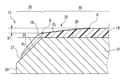
- FIG. 2 is a schematic view showing an AA cross section of the half bearing 13. That is, FIG. 2 shows a cross section of the half bearing 13 parallel to the axial direction (and perpendicular to the sliding direction).
- the mating shaft that slides is not shown in FIG. 2, the mating shaft is at the top of the drawing. That is, the upper surface in the drawing is a sliding surface.
- the layers are stacked in the order of the overlay layer 19, the lining layer 17, and the back metal 15 in order from the side closer to the mating shaft.
- chamfered portions 25 are formed at the ends of the sliding surface 28 for the purpose of preventing removal or generation of burrs or the like.
- the angle ⁇ 1 of the chamfered portion with respect to the sliding surface 28 is, for example, in the range of 30 to 60 °.
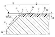
- FIG. 3 is an enlarged view of a portion B of FIG.
- the overlay layer 19 extends in the axial direction (left and right direction in FIG. 2) and covers at least a part of the sliding surface 28 and the chamfer 25. That is, the overlay layer 19 is formed at a position where the interface 27 with the lining layer 17 does not receive the load of the opposite shaft.
- a position not receiving the load of the mating shaft refers to a position that covers at least a part of the chamfered portion 25.
- the overlay layer 19 has a crowning shape.
- the crowning shape is a shape that is gently inclined.
- the inclination angle ⁇ 2 is, for example, in the range of 0 to 10 °.
- the overlay layer 19 is inclined from the inclination start position P toward the axial end 23.
- the distance w1 from the axial end surface 24 to the inclination start position P satisfies w1 ⁇ W / 2.
- W is the distance between the two axial end faces 24 (ie the width of the bearing).
- the difference in film thickness (difference in height of the overlay layer 19) S1 between the inclination start position P and the axial end position D of the sliding surface 28 is preferably 6 ⁇ m or less.
- FIG. 4 is a view illustrating another shape of the axial end.
- the overlay layer 19 has a raised portion 29.
- the raised portion 29 is a portion that is higher (thicker) than the other portions.
- the raised portion 29 is a portion outside the inclination start position P (on the end side of the inclination start position P).
- the distance w1 from the axial end surface 24 to the inclination start position P satisfies w1 ⁇ W / 2.
- W is the distance between the two axial end faces 24.
- the difference S2 in height between the apex 31 of the raised portion 29 and the other portion of the overlay layer 19 is preferably 6 ⁇ m or less.
- the height of the other portion of the overlay layer 19 is a representative value of the height of the portion of the overlay layer 19 other than the raised portion 29, and is, for example, an average value.
- the height of the axially central portion of the overlay layer 19 may be used as a representative value.
- the overlay layer 19 starts crowning from the top 31 of the raised portion 29. Therefore, it is preferable that the film thickness difference S3 between the apex 31 of the raised portion 29 and the axial direction end position D be 6 ⁇ m or less.
- the oil holding portion 33 between the inner peripheral surface of the main bearing 11 and the opposite shaft can easily hold lubricating oil when the engine is stopped. Become. Further, the lubricating oil can be easily drawn in between the mating shaft and the main bearing 11 at the time of start-up. As a result, the oil film thickness is increased, and the contact between the mating shaft and the main bearing 11 at the start is alleviated.
- FIG. 5 is a view showing the structure of a sliding member according to the related art. This figure is an enlarged view of a position corresponding to part B of FIG.
- an overlay layer 419 is formed on the lining layer 17.
- the overlay layer 419 is not formed on the chamfered portion 25 but is formed only on the sliding surface 28. That is, the overlay layer 419 is formed inside the end position 18 of the sliding surface 28 (the boundary between the sliding surface 28 and the chamfered portion 25). That is, in this example, it can be said that the end of the overlay layer 419 is formed at a position where it can easily receive the load of the mating shaft.
- the overlay layer 19 is formed up to the chamfered portion 25. Therefore, compared with the structure of FIG. 5, the adhesion area with the base material (lining layer 17) is increased, and the adhesion amount is improved. Also, at the edge of the overlay layer, lubricating oil may intrude from the interface with the substrate to cause peeling of the overlay layer. However, in the present embodiment, since the interface with the overlay layer 19 is not exposed in the vicinity of the sliding surface 28, the possibility of lubricating oil entering can be reduced compared to the structure of FIG. 5. .
- the interface between the overlay layer 19 and the lining layer 17 is formed at a position where the load of the mating shaft is unlikely to be received, it is possible to reduce film peeling caused by the load of the mating shaft. Furthermore, since the chamfered portion 25 is unlikely to slide with the mating shaft, the portion of the overlay layer 19 covering the chamfered portion 25 has less influence on the sliding characteristics. That is, the overlay layer 19 can be formed without requiring a manufacturing cost for this portion.
- Method of Manufacturing includes the following steps. (A) Step of preparing overlay precursor containing solid lubricant and binder resin (b) Step of forming bearing substrate (c) Step of applying overlay precursor on bearing substrate (d) overlay precursor Drying (e) baking the overlay precursor
- the method of mixing the solid lubricant and the binder resin is not particularly limited, and known methods can be used.
- the overlay precursor is prepared by placing a solid lubricant and a binder resin in a kneader and mixing them at a shear rate of 0.1 to 2 m / s.
- the binder resin may be incompatible, but is preferably at least partially compatible from the viewpoint of practical use.
- the compatiblity may be mechanically blended with high shear.
- the backing metal and the bearing alloy layer are, for example, pressure-welded to form a bearing base. Furthermore, the bearing base is processed into a predetermined shape, for example, a cylindrical or semi-cylindrical shape.
- a diluent in order to uniformly disperse the solid lubricant and the binder resin.
- the diluent is not particularly limited, and for example, N-methylpyrrolidone (NMP) is used. Further, the blending ratio of the diluent is, for example, 30 to 70% by volume with respect to the solid content.
- the precursor solution can be thinly applied and divided several times to suppress the rise of the axial end 35 of the sliding surface 28. That is, it is possible to prevent local contact and burning of the mating shaft and the raised portion 29 of the resin overlay layer 19.
- the axial end and the non-axial end can be separately coated, and a crowning shape can be formed. Also in this case, it is possible to suppress the swelling due to the surface tension of the axial direction end by coating as thin as described above several times.
- a roll-based coating is employed, a roll shaped according to the desired overlay shape is used.
- the coating of the chamfered portion 25 uses a roll having an axial width substantially equal to the axial length of the sliding surface 28 on the inner circumferential surface, and using the coating liquid protruding from both ends of the roll as it is It is also good. This is because the shape and thickness of the coating of the chamfered portion 25 can have a considerable allowance.
- the diluent is removed by drying the overlay precursor in step (d).
- the conditions such as the drying time and the drying temperature are not particularly limited as long as the diluent is dried, but it is preferable to dry, for example, at 50 to 150 ° C. for 5 minutes to 30 hours in the atmosphere.
- the drying time is more preferably 5 to 30 minutes.
- step (e) By baking in step (e), a bearing having an overlay layer formed thereon can be obtained.
- the temperature of the bearing base after step (d) is gradually raised to the firing temperature at a heating rate of 5 to 15 ° C./min, and the temperature is 150 to 300 ° C. in the air, 0.2 to 1 Bake for 5 hours.
- the preparation method of a sample is as follows. An aluminum alloy was pressure-welded to the steel backing metal 15 as the lining layer 17. This material was processed into a half-cylindrical shape. The material of the overlay layer 19 was diluted with a solvent (N-methyl-2-pyrrolidone) to prepare a coating solution. The coating solution was coated by an air spray method. Next, after drying at 100 ° C. for 20 minutes, baking was performed at 200 ° C. for 60 minutes.
- a rotary load tester manufactured by Shinko Machine Co., Ltd. was used for measuring the starting torque. This tester is composed of a load bearing housing connected to a shaft by two sets of test bearings assembled in a housing and a ball bearing, and the other shaft is connected to a drive motor via a torque meter. ing. Refueling to the test section takes place from the housing through the oil holes in the bearings. The same lubricating oil was used as the engine oil used to measure the contact angle. The fueling temperature was 30 ° C.
- the operation pattern is start-stop, 10 seconds for acceleration (1.7 m / s) up to a shaft rotational speed of 700 rpm and constant speed operation, and 10 seconds for one cycle of 10 seconds for deceleration and stop.
- the load always applied 2000 N (1.2 MPa).
- the number of cycles was 180 and the test time was 1 hour.
- the start-up torque measurement the torque peak value generated at the start-up is measured.
- the evaluation was made by comparing the average value of the measured values for the final 20 cycles.
- the samples having a height difference of 1 to 6 ⁇ m and an inclination start position w / W of less than 1/2 all have a start torque of less than 2.0 Nm and a seizure surface pressure of Good characteristics of 80 MPa or more were exhibited.
- the seizure surface pressure is less than 80 MPa.
- the starting torque was 2.1 Nm or more, and the seizure surface pressure was less than 70 MPa.
Landscapes
- Chemical & Material Sciences (AREA)
- Engineering & Computer Science (AREA)
- General Engineering & Computer Science (AREA)
- Organic Chemistry (AREA)
- Chemical Kinetics & Catalysis (AREA)
- Mechanical Engineering (AREA)
- Health & Medical Sciences (AREA)
- Medicinal Chemistry (AREA)
- Polymers & Plastics (AREA)
- Life Sciences & Earth Sciences (AREA)
- Materials Engineering (AREA)
- Wood Science & Technology (AREA)
- Inorganic Chemistry (AREA)
- General Chemical & Material Sciences (AREA)
- Oil, Petroleum & Natural Gas (AREA)
- Sliding-Contact Bearings (AREA)
Abstract
Description
図1は、一実施形態に係る主軸受(すべり軸受)11の構造を示す図である。主軸受11は摺動部材の一例であり、例えば、内燃機関のクランクシャフトとコネクティングロッド、またはクランクシャフトとエンジンブロックの間の軸受として用いられる。主軸受11は、2つの半割軸受13により構成される。2つの半割軸受13を接合すると円筒状の軸受が得られる。なお、図1においては、単一の半割軸受13のみを示している。
一実施形態に係る軸受の製造方法は、以下に示す工程を含む。
(a)固体潤滑剤およびバインダー樹脂を含むオーバレイ前駆体を調製する工程
(b)軸受基材を成形する工程
(c)軸受基材上に、オーバレイ前駆体を塗布する工程
(d)オーバレイ前駆体を乾燥させる工程
(e)オーバレイ前駆体を焼成する工程
オーバレイ層19の膜厚差(高さの差)dおよび傾斜開始位置Pを変化させた試料(実施例1~8および比較例1~5)を作製し、これらの試料において起動トルクおよび焼付き面圧を測定した。なお起動トルクは、相手軸23と主軸受11との間に形成される油膜の厚さを示す指標である。油膜の厚さを直接測定することは困難であるので、油膜の厚さを示す指標として起動トルクを測定した。起動トルクがより小さいと油膜がより厚いことが示される。焼付き面圧は、耐焼付き性を示す指標である。焼付き面圧が高いほど耐焼付き性に優れていることが示される。焼付き面圧が高いということは、オーバレイ層の剥離が起こりにくいということを示している。
まず、試料の作製方法は以下のとおりである。鋼製の裏金15に、アルミニウム合金をライニング層17として圧接した。この材料を半割り円筒形状に加工した。オーバレイ層19の材料を溶剤(N-メチル-2-ピロリドン)で希釈して塗布液を調整した。この塗布液をエアースプレー方法でコーティングした。次に、100℃、20minで乾燥した後、200℃、60minで焼成を行った。
軸受幅K:15mm
オーバレイ層の中央膜厚:6μm
オーバレイ層の成分:バインダー樹脂(PAI) 58体積%
固体潤滑剤(グラファイト) 40体積%
硬質物(SiC) 1体積%
各試料におけるオーバレイ層19の膜厚差hおよび傾斜開始位置Pは表1に記載されている。
起動トルクの測定には、神鋼造機製の回転荷重試験機を用いた。この試験機は、ハウジングに組み付けられた二組の試験軸受部とボールベアリングで軸と連結された荷重負荷用ハウジングで構成されており、相手軸はトルク計を介して駆動用のモーターに連結されている。試験部への給油はハウジングから軸受の油穴を通して行われる。潤滑油は、接触角の測定に用いたエンジン油と同じものを用いた。給油温度は30℃とした。運転パターンは、起動-停止とし、軸回転速度700rpmまでの加速(1.7m/s)と定速運転で10秒、減速と停止で10秒の1サイクル20秒とした。荷重は2000N(1.2MPa)を常時負荷した。サイクル数は180サイクル、試験時間は1時間とした。起動トルク測定では、起動時に発生するトルクピーク値を測定するが、試験初期はトルクのばらつきが大きいため、終盤20サイクルを対象にしてその測定値の平均値で比較評価した。
下記に示す条件で焼付き試験を行い、焼付きに至った面圧を焼付面圧として測定した。
回転数:8000rpm
潤滑油:0W-20
給油温度:140℃
荷重:3分毎に3kNずつ荷重漸増
評価結果を表1に示す。

Claims (7)
- 相手軸と摺動する摺動面および当該摺動面の軸方向端部に設けられた面取り部を有するライニング層と、
樹脂で形成され前記面取り部の少なくとも一部を覆うオーバレイ層と
を有する摺動部材。 - 前記オーバレイ層は、前記ライニング層の軸方向の幅をWとしたときに、軸方向端面からの距離がW/2よりも短い位置を傾斜開始位置として、前記軸方向端部に向かって傾斜するクラウニング形状を有する
ことを特徴とする請求項1に記載の摺動部材。 - 前記オーバレイ層において、前記傾斜開始位置と前記摺動面の軸方向端部位置との高さの差が6μm以下である
ことを特徴とする請求項2に記載の摺動部材。 - 前記オーバレイ層は、
バインダー樹脂と、
固体潤滑材および硬質物の少なくとも一方と
を含むことを特徴とする請求項1ないし3のいずれか一項に記載の摺動部材。 - 前記バインダー樹脂は、ポリアミドイミド樹脂、ポリイミド樹脂、エポキシ樹脂、フェノール樹脂、ポリアセタール樹脂、ポリエーテルエーテルケトン樹脂、およびポリフェニレンサルファイド樹脂の少なくとも1つを含む
ことを特徴とする請求項4に記載の摺動部材。 - 前記固体潤滑材は、MoS2、PTFE、グラファイト、WS2、h-BN、およびSB203の少なくとも1つを含む
ことを特徴とする請求項4または5に記載の摺動部材。 - 前記硬質物は、SiC、Al203、TiN、AIN、CrO2、Si3N4、ZrO2、およびPの少なくとも1つを含む
ことを特徴とする請求項4ないし6のいずれか一項に記載の摺動部材。
Priority Applications (4)
| Application Number | Priority Date | Filing Date | Title |
|---|---|---|---|
| EP14751585.2A EP2957784B1 (en) | 2013-02-15 | 2014-02-14 | Sliding member |
| JP2015500310A JP6012843B2 (ja) | 2013-02-15 | 2014-02-14 | 摺動部材 |
| US14/768,105 US9709093B2 (en) | 2013-02-15 | 2014-02-14 | Sliding member |
| CN201480020890.0A CN105164437B (zh) | 2013-02-15 | 2014-02-14 | 滑动构件 |
Applications Claiming Priority (2)
| Application Number | Priority Date | Filing Date | Title |
|---|---|---|---|
| JP2013027955 | 2013-02-15 | ||
| JP2013-027955 | 2013-02-15 |
Publications (1)
| Publication Number | Publication Date |
|---|---|
| WO2014126202A1 true WO2014126202A1 (ja) | 2014-08-21 |
Family
ID=51354201
Family Applications (1)
| Application Number | Title | Priority Date | Filing Date |
|---|---|---|---|
| PCT/JP2014/053483 WO2014126202A1 (ja) | 2013-02-15 | 2014-02-14 | 摺動部材 |
Country Status (5)
| Country | Link |
|---|---|
| US (1) | US9709093B2 (ja) |
| EP (1) | EP2957784B1 (ja) |
| JP (2) | JP6012843B2 (ja) |
| CN (1) | CN105164437B (ja) |
| WO (1) | WO2014126202A1 (ja) |
Cited By (3)
| Publication number | Priority date | Publication date | Assignee | Title |
|---|---|---|---|---|
| EP3029342A1 (en) * | 2014-09-26 | 2016-06-08 | Honda Motor Co., Ltd. | Connecting rod for internal combustion engine |
| WO2019175924A1 (ja) * | 2018-03-12 | 2019-09-19 | 日産自動車株式会社 | 軸受部材 |
| US11231067B2 (en) * | 2018-05-10 | 2022-01-25 | Nissan Motor Co., Ltd. | Bearing member |
Families Citing this family (13)
| Publication number | Priority date | Publication date | Assignee | Title |
|---|---|---|---|---|
| GB2507768A (en) * | 2012-11-08 | 2014-05-14 | Mahle Int Gmbh | A half bearing for a sliding bearing |
| WO2017042201A1 (en) | 2015-09-07 | 2017-03-16 | Ikea Supply Ag | A sliding screen sliding system |
| WO2017044032A1 (en) | 2015-09-07 | 2017-03-16 | Ikea Supply Ag | Low friction slide member |
| EP3346874B1 (en) | 2015-09-07 | 2019-08-14 | IKEA Supply AG | A drawer, and a drawer sliding system for such drawer |
| GB2552997B (en) | 2016-08-19 | 2022-01-05 | Mahle Int Gmbh | Sliding component and method |
| CN106321635B (zh) * | 2016-09-12 | 2019-02-01 | 中国科学院兰州化学物理研究所 | 发动机低摩擦轴瓦及其制备方法 |
| SE540785C2 (en) * | 2017-03-03 | 2018-11-13 | Ikea Supply Ag | A furniture rotary system having reduced friction, and a piece of furniture comprising such system |
| SE540465C2 (en) | 2017-03-03 | 2018-09-18 | Ikea Supply Ag | Furniture lubricant comprising a C10 to C28 alkane and a triglyceride |
| JP6574826B2 (ja) * | 2017-11-10 | 2019-09-11 | 大同メタル工業株式会社 | 半割スラスト軸受、スラスト軸受、軸受装置および内燃機関 |
| DE102018117712A1 (de) * | 2018-07-23 | 2020-01-23 | Schreiber Brücken Dehntechnik GmbH | Gleitlager im Bauwesen |
| US11326118B2 (en) * | 2018-08-06 | 2022-05-10 | Eneos Corporation | Lubrication method |
| WO2020072572A1 (en) | 2018-10-04 | 2020-04-09 | Cummins Inc. | Crankshaft thrust bearing |
| MX2023014548A (es) | 2021-07-02 | 2024-01-31 | Saint Gobain Performance Plastics Pampus Gmbh | Cojinete de brida, montaje y metodo para elaborar y usar estos. |
Citations (5)
| Publication number | Priority date | Publication date | Assignee | Title |
|---|---|---|---|---|
| JPH07238936A (ja) * | 1994-02-28 | 1995-09-12 | Taiho Kogyo Co Ltd | すべり軸受材料 |
| JP3388501B2 (ja) | 1998-06-29 | 2003-03-24 | 大同メタル工業株式会社 | すべり軸受 |
| JP2005265043A (ja) * | 2004-03-18 | 2005-09-29 | Daido Metal Co Ltd | すべり軸受 |
| WO2010038588A1 (ja) * | 2008-10-03 | 2010-04-08 | 大豊工業株式会社 | すべり軸受とその製造方法 |
| JP2010196813A (ja) * | 2009-02-25 | 2010-09-09 | Daido Metal Co Ltd | 摺動部材 |
Family Cites Families (9)
| Publication number | Priority date | Publication date | Assignee | Title |
|---|---|---|---|---|
| DE3816404A1 (de) * | 1988-05-13 | 1989-11-30 | Mtu Friedrichshafen Gmbh | Dreistoffgleitlager |
| JPH10299780A (ja) * | 1997-04-29 | 1998-11-10 | Daido Metal Co Ltd | すべり軸受 |
| US6669371B2 (en) * | 2000-05-19 | 2003-12-30 | Asmo Co., Ltd. | Oil-impregnated sintered bearing |
| JP2002039183A (ja) * | 2000-05-19 | 2002-02-06 | Asmo Co Ltd | 焼結含油軸受 |
| JP2002155945A (ja) * | 2000-11-20 | 2002-05-31 | Daido Metal Co Ltd | 軸支承部材 |
| JP3955737B2 (ja) * | 2001-03-07 | 2007-08-08 | 大同メタル工業株式会社 | すべり軸受 |
| EP1522750B2 (en) * | 2003-10-06 | 2018-02-14 | Taiho Kogyo Co., Ltd | Multi-layer sliding bearing |
| JP5352978B2 (ja) * | 2007-09-11 | 2013-11-27 | 株式会社ダイヤメット | 焼結軸受の製造方法 |
| DE102008055194A1 (de) | 2008-12-30 | 2010-07-08 | Federal-Mogul Wiesbaden Gmbh | Gleitelement |
-
2014
- 2014-02-14 CN CN201480020890.0A patent/CN105164437B/zh active Active
- 2014-02-14 JP JP2015500310A patent/JP6012843B2/ja active Active
- 2014-02-14 EP EP14751585.2A patent/EP2957784B1/en not_active Revoked
- 2014-02-14 WO PCT/JP2014/053483 patent/WO2014126202A1/ja active Application Filing
- 2014-02-14 US US14/768,105 patent/US9709093B2/en active Active
-
2016
- 2016-07-12 JP JP2016137423A patent/JP6177392B2/ja active Active
Patent Citations (5)
| Publication number | Priority date | Publication date | Assignee | Title |
|---|---|---|---|---|
| JPH07238936A (ja) * | 1994-02-28 | 1995-09-12 | Taiho Kogyo Co Ltd | すべり軸受材料 |
| JP3388501B2 (ja) | 1998-06-29 | 2003-03-24 | 大同メタル工業株式会社 | すべり軸受 |
| JP2005265043A (ja) * | 2004-03-18 | 2005-09-29 | Daido Metal Co Ltd | すべり軸受 |
| WO2010038588A1 (ja) * | 2008-10-03 | 2010-04-08 | 大豊工業株式会社 | すべり軸受とその製造方法 |
| JP2010196813A (ja) * | 2009-02-25 | 2010-09-09 | Daido Metal Co Ltd | 摺動部材 |
Non-Patent Citations (1)
| Title |
|---|
| See also references of EP2957784A4 |
Cited By (4)
| Publication number | Priority date | Publication date | Assignee | Title |
|---|---|---|---|---|
| EP3029342A1 (en) * | 2014-09-26 | 2016-06-08 | Honda Motor Co., Ltd. | Connecting rod for internal combustion engine |
| WO2019175924A1 (ja) * | 2018-03-12 | 2019-09-19 | 日産自動車株式会社 | 軸受部材 |
| US11193537B2 (en) | 2018-03-12 | 2021-12-07 | Nissan Motor Co., Ltd. | Bearing member |
| US11231067B2 (en) * | 2018-05-10 | 2022-01-25 | Nissan Motor Co., Ltd. | Bearing member |
Also Published As
| Publication number | Publication date |
|---|---|
| US20160091022A1 (en) | 2016-03-31 |
| JPWO2014126202A1 (ja) | 2017-02-02 |
| JP6012843B2 (ja) | 2016-10-25 |
| EP2957784A1 (en) | 2015-12-23 |
| CN105164437A (zh) | 2015-12-16 |
| CN105164437B (zh) | 2019-07-19 |
| JP6177392B2 (ja) | 2017-08-09 |
| EP2957784B1 (en) | 2019-04-10 |
| EP2957784A4 (en) | 2016-11-02 |
| JP2016186366A (ja) | 2016-10-27 |
| US9709093B2 (en) | 2017-07-18 |
Similar Documents
| Publication | Publication Date | Title |
|---|---|---|
| JP6177392B2 (ja) | 半割軸受 | |
| JP6473621B2 (ja) | 摺動部材 | |
| JP6122488B2 (ja) | 摺動部材 | |
| EP1894987B1 (en) | Double-layer lubrication coating composition, double-layer lubrication coating and piston having same coating | |
| JP6313780B2 (ja) | スラストワッシャー | |
| WO2010073811A1 (ja) | 斜板とその製造方法 | |
| JP2013245767A (ja) | すべり軸受 | |
| KR100685546B1 (ko) | 다층 미끄럼 베어링 재료 | |
| JP4767234B2 (ja) | 摺動用被覆構造 | |
| JP5878061B2 (ja) | すべり軸受 | |
| JP3844206B2 (ja) | 摺動部材 | |
| JP2015200339A (ja) | 摺動部材 | |
| JP5878062B2 (ja) | すべり軸受 | |
| JP7463421B2 (ja) | 摺動部材 | |
| JP5816121B2 (ja) | すべり軸受とその製造方法 | |
| CN114250099A (zh) | 具有固体润滑剂的轴承材料 | |
| JP2018035838A (ja) | スラストワッシャ | |
| JP5717069B2 (ja) | ピストン及び摺動用被覆構造 | |
| JP2014234860A (ja) | すべり軸受 | |
| CN109983241A (zh) | 半轴承 | |
| CN117545934A (zh) | 具有中间层的滑动元件 | |
| JP5568666B2 (ja) | 複層被膜組成物が施された内燃機関のピストン及び該ピストンの表面処理方法 | |
| CN110214235A (zh) | 半轴承 |
Legal Events
| Date | Code | Title | Description |
|---|---|---|---|
| WWE | Wipo information: entry into national phase |
Ref document number: 201480020890.0 Country of ref document: CN |
|
| 121 | Ep: the epo has been informed by wipo that ep was designated in this application |
Ref document number: 14751585 Country of ref document: EP Kind code of ref document: A1 |
|
| ENP | Entry into the national phase |
Ref document number: 2015500310 Country of ref document: JP Kind code of ref document: A |
|
| NENP | Non-entry into the national phase |
Ref country code: DE |
|
| WWE | Wipo information: entry into national phase |
Ref document number: 2014751585 Country of ref document: EP |
|
| WWE | Wipo information: entry into national phase |
Ref document number: 14768105 Country of ref document: US |