EP3029342A1 - Connecting rod for internal combustion engine - Google Patents
Connecting rod for internal combustion engine Download PDFInfo
- Publication number
- EP3029342A1 EP3029342A1 EP15177841.2A EP15177841A EP3029342A1 EP 3029342 A1 EP3029342 A1 EP 3029342A1 EP 15177841 A EP15177841 A EP 15177841A EP 3029342 A1 EP3029342 A1 EP 3029342A1
- Authority
- EP
- European Patent Office
- Prior art keywords
- coating
- tapered
- connecting rod
- surface portion
- base material
- Prior art date
- Legal status (The legal status is an assumption and is not a legal conclusion. Google has not performed a legal analysis and makes no representation as to the accuracy of the status listed.)
- Granted
Links
Images


Classifications
-
- B—PERFORMING OPERATIONS; TRANSPORTING
- B21—MECHANICAL METAL-WORKING WITHOUT ESSENTIALLY REMOVING MATERIAL; PUNCHING METAL
- B21K—MAKING FORGED OR PRESSED METAL PRODUCTS, e.g. HORSE-SHOES, RIVETS, BOLTS OR WHEELS
- B21K1/00—Making machine elements
- B21K1/76—Making machine elements elements not mentioned in one of the preceding groups
- B21K1/766—Connecting rods
-
- F—MECHANICAL ENGINEERING; LIGHTING; HEATING; WEAPONS; BLASTING
- F16—ENGINEERING ELEMENTS AND UNITS; GENERAL MEASURES FOR PRODUCING AND MAINTAINING EFFECTIVE FUNCTIONING OF MACHINES OR INSTALLATIONS; THERMAL INSULATION IN GENERAL
- F16C—SHAFTS; FLEXIBLE SHAFTS; ELEMENTS OR CRANKSHAFT MECHANISMS; ROTARY BODIES OTHER THAN GEARING ELEMENTS; BEARINGS
- F16C23/00—Bearings for exclusively rotary movement adjustable for aligning or positioning
- F16C23/02—Sliding-contact bearings
- F16C23/04—Sliding-contact bearings self-adjusting
- F16C23/041—Sliding-contact bearings self-adjusting with edge relief
-
- F—MECHANICAL ENGINEERING; LIGHTING; HEATING; WEAPONS; BLASTING
- F16—ENGINEERING ELEMENTS AND UNITS; GENERAL MEASURES FOR PRODUCING AND MAINTAINING EFFECTIVE FUNCTIONING OF MACHINES OR INSTALLATIONS; THERMAL INSULATION IN GENERAL
- F16C—SHAFTS; FLEXIBLE SHAFTS; ELEMENTS OR CRANKSHAFT MECHANISMS; ROTARY BODIES OTHER THAN GEARING ELEMENTS; BEARINGS
- F16C33/00—Parts of bearings; Special methods for making bearings or parts thereof
- F16C33/02—Parts of sliding-contact bearings
- F16C33/04—Brasses; Bushes; Linings
- F16C33/06—Sliding surface mainly made of metal
- F16C33/14—Special methods of manufacture; Running-in
-
- F—MECHANICAL ENGINEERING; LIGHTING; HEATING; WEAPONS; BLASTING
- F16—ENGINEERING ELEMENTS AND UNITS; GENERAL MEASURES FOR PRODUCING AND MAINTAINING EFFECTIVE FUNCTIONING OF MACHINES OR INSTALLATIONS; THERMAL INSULATION IN GENERAL
- F16C—SHAFTS; FLEXIBLE SHAFTS; ELEMENTS OR CRANKSHAFT MECHANISMS; ROTARY BODIES OTHER THAN GEARING ELEMENTS; BEARINGS
- F16C9/00—Bearings for crankshafts or connecting-rods; Attachment of connecting-rods
- F16C9/04—Connecting-rod bearings; Attachments thereof
-
- F—MECHANICAL ENGINEERING; LIGHTING; HEATING; WEAPONS; BLASTING
- F16—ENGINEERING ELEMENTS AND UNITS; GENERAL MEASURES FOR PRODUCING AND MAINTAINING EFFECTIVE FUNCTIONING OF MACHINES OR INSTALLATIONS; THERMAL INSULATION IN GENERAL
- F16J—PISTONS; CYLINDERS; SEALINGS
- F16J7/00—Piston-rods
-
- F—MECHANICAL ENGINEERING; LIGHTING; HEATING; WEAPONS; BLASTING
- F16—ENGINEERING ELEMENTS AND UNITS; GENERAL MEASURES FOR PRODUCING AND MAINTAINING EFFECTIVE FUNCTIONING OF MACHINES OR INSTALLATIONS; THERMAL INSULATION IN GENERAL
- F16C—SHAFTS; FLEXIBLE SHAFTS; ELEMENTS OR CRANKSHAFT MECHANISMS; ROTARY BODIES OTHER THAN GEARING ELEMENTS; BEARINGS
- F16C17/00—Sliding-contact bearings for exclusively rotary movement
- F16C17/02—Sliding-contact bearings for exclusively rotary movement for radial load only
-
- F—MECHANICAL ENGINEERING; LIGHTING; HEATING; WEAPONS; BLASTING
- F16—ENGINEERING ELEMENTS AND UNITS; GENERAL MEASURES FOR PRODUCING AND MAINTAINING EFFECTIVE FUNCTIONING OF MACHINES OR INSTALLATIONS; THERMAL INSULATION IN GENERAL
- F16C—SHAFTS; FLEXIBLE SHAFTS; ELEMENTS OR CRANKSHAFT MECHANISMS; ROTARY BODIES OTHER THAN GEARING ELEMENTS; BEARINGS
- F16C2202/00—Solid materials defined by their properties
- F16C2202/02—Mechanical properties
- F16C2202/04—Hardness
-
- F—MECHANICAL ENGINEERING; LIGHTING; HEATING; WEAPONS; BLASTING
- F16—ENGINEERING ELEMENTS AND UNITS; GENERAL MEASURES FOR PRODUCING AND MAINTAINING EFFECTIVE FUNCTIONING OF MACHINES OR INSTALLATIONS; THERMAL INSULATION IN GENERAL
- F16C—SHAFTS; FLEXIBLE SHAFTS; ELEMENTS OR CRANKSHAFT MECHANISMS; ROTARY BODIES OTHER THAN GEARING ELEMENTS; BEARINGS
- F16C2223/00—Surface treatments; Hardening; Coating
- F16C2223/02—Mechanical treatment, e.g. finishing
- F16C2223/06—Mechanical treatment, e.g. finishing polishing
-
- F—MECHANICAL ENGINEERING; LIGHTING; HEATING; WEAPONS; BLASTING
- F16—ENGINEERING ELEMENTS AND UNITS; GENERAL MEASURES FOR PRODUCING AND MAINTAINING EFFECTIVE FUNCTIONING OF MACHINES OR INSTALLATIONS; THERMAL INSULATION IN GENERAL
- F16C—SHAFTS; FLEXIBLE SHAFTS; ELEMENTS OR CRANKSHAFT MECHANISMS; ROTARY BODIES OTHER THAN GEARING ELEMENTS; BEARINGS
- F16C2223/00—Surface treatments; Hardening; Coating
- F16C2223/30—Coating surfaces
-
- F—MECHANICAL ENGINEERING; LIGHTING; HEATING; WEAPONS; BLASTING
- F16—ENGINEERING ELEMENTS AND UNITS; GENERAL MEASURES FOR PRODUCING AND MAINTAINING EFFECTIVE FUNCTIONING OF MACHINES OR INSTALLATIONS; THERMAL INSULATION IN GENERAL
- F16C—SHAFTS; FLEXIBLE SHAFTS; ELEMENTS OR CRANKSHAFT MECHANISMS; ROTARY BODIES OTHER THAN GEARING ELEMENTS; BEARINGS
- F16C2240/00—Specified values or numerical ranges of parameters; Relations between them
- F16C2240/30—Angles, e.g. inclinations
-
- F—MECHANICAL ENGINEERING; LIGHTING; HEATING; WEAPONS; BLASTING
- F16—ENGINEERING ELEMENTS AND UNITS; GENERAL MEASURES FOR PRODUCING AND MAINTAINING EFFECTIVE FUNCTIONING OF MACHINES OR INSTALLATIONS; THERMAL INSULATION IN GENERAL
- F16C—SHAFTS; FLEXIBLE SHAFTS; ELEMENTS OR CRANKSHAFT MECHANISMS; ROTARY BODIES OTHER THAN GEARING ELEMENTS; BEARINGS
- F16C2240/00—Specified values or numerical ranges of parameters; Relations between them
- F16C2240/40—Linear dimensions, e.g. length, radius, thickness, gap
- F16C2240/60—Thickness, e.g. thickness of coatings
-
- F—MECHANICAL ENGINEERING; LIGHTING; HEATING; WEAPONS; BLASTING
- F16—ENGINEERING ELEMENTS AND UNITS; GENERAL MEASURES FOR PRODUCING AND MAINTAINING EFFECTIVE FUNCTIONING OF MACHINES OR INSTALLATIONS; THERMAL INSULATION IN GENERAL
- F16C—SHAFTS; FLEXIBLE SHAFTS; ELEMENTS OR CRANKSHAFT MECHANISMS; ROTARY BODIES OTHER THAN GEARING ELEMENTS; BEARINGS
- F16C2360/00—Engines or pumps
- F16C2360/22—Internal combustion engines
-
- F—MECHANICAL ENGINEERING; LIGHTING; HEATING; WEAPONS; BLASTING
- F16—ENGINEERING ELEMENTS AND UNITS; GENERAL MEASURES FOR PRODUCING AND MAINTAINING EFFECTIVE FUNCTIONING OF MACHINES OR INSTALLATIONS; THERMAL INSULATION IN GENERAL
- F16C—SHAFTS; FLEXIBLE SHAFTS; ELEMENTS OR CRANKSHAFT MECHANISMS; ROTARY BODIES OTHER THAN GEARING ELEMENTS; BEARINGS
- F16C33/00—Parts of bearings; Special methods for making bearings or parts thereof
- F16C33/02—Parts of sliding-contact bearings
- F16C33/04—Brasses; Bushes; Linings
- F16C33/06—Sliding surface mainly made of metal
- F16C33/12—Structural composition; Use of special materials or surface treatments, e.g. for rust-proofing
- F16C33/121—Use of special materials
Landscapes
- Engineering & Computer Science (AREA)
- General Engineering & Computer Science (AREA)
- Mechanical Engineering (AREA)
- Shafts, Cranks, Connecting Bars, And Related Bearings (AREA)
- Pistons, Piston Rings, And Cylinders (AREA)
Abstract
Description
- The present invention relates to a connecting rod for an internal combustion engine.
- In an internal combustion engine, a connecting rod connects a piston pin to a crankpin so that the reciprocating motion of the piston along the axis of the cylinder is converted to the rotating motion of the crankshaft. The connecting rod has a small-diameter connecting hole formed in one end (the "little end") for connection to the piston pin, and a large-diameter connecting hole formed in the other end (the "big end") for connection to the crankpin.
- During operation of the internal combustion engine, a large load acts at an edge of the connecting hole of the connecting rod on a power transmitting pin such as the piston pin, the crankpin or the like. Therefore, to improve wear resistance of the power transmitting pin, a connecting rod is formed such that the inner peripheral face of a hole in the connecting rod, formed from connecting rod base material, is covered with a coating material which is softer than the connecting rod base material, by plating or the like (for example, see
JP-A No. 2001-511500 - In the above-described prior art connecting rod, when a large load acts on the power transmitting pin at the edge of the connecting hole, the softer coating material applied to the connecting hole is elastically deformed, which thereby reduces the contact pressure acting on the power transmitting pin from the edge of the connecting hole.
- As the engine operating speed in an internal combustion engine is increased, the power transmitting pin bends, so that the axial end of the power transmitting pin is strongly pressed against a portion around the axially outer end of the connecting hole of the connecting rod.
- However, in the above-described prior art connecting rod, the inner peripheral face of the connecting hole has a constant inner diameter and is uniformly coated with the coating material. Because of this, it is difficult to efficiently reduce the pressure exerted on a portion of the power transmitting pin as a result of coming into contact with a portion around the axially outer end of the connecting hole.
- Accordingly, at least in its preferred embodiments, the present invention provides a connecting rod for an internal combustion engine enabling an efficient reduction in contact pressure exerted on a power transmitting pin from a region around an axially outer end of a connecting hole.
- According to a first aspect of the present invention, there is provided a connecting rod for an internal combustion engine, comprising: a connecting hole through which a power transmitting pin is slidably fitted, the connecting hole being formed by coating an inner peripheral surface of a base material hole formed in a connecting rod base material with a coating material which is softer than the connecting rod base material, wherein the base material hole includes: a cylindrical inner surface portion with a constant inner diameter, formed in an axially central region; and a tapered inner surface portion that is continuous with an axially outer side of the cylindrical inner surface portion and is radially enlarged in an axially outward direction, and wherein the coating layer formed from the coating material includes: a first coating portion deposited on the cylindrical inner surface portion and having an inner face with an approximately constant inner diameter; and a second coating portion deposited on the tapered inner surface portion to adjoin the first coating portion and gradually increasing in material thickness in the axially outward direction.
- Because the softer coating material is deposited on the tapered inner surface portion of the base material hole, and the thickness of the second coating portion continuous with the first coating portion gradually increases toward the outside in the axial direction, the cushioning effect produced by the coating material is enhanced more in an axially further outward region of the connecting hole when the power transmitting pin fitted through the connecting hole bends.
- Preferably, an inner peripheral face of the second coating portion is formed continuously with an inner peripheral face of the first coating portion so as to have an approximately constant inner diameter.
- In this case, when the bending of the power transmitting pin is small, the power transmitting pin can be supported across a wide extent of the first coating portion and the second coating portion. Accordingly, a reduction in contact pressure on the power transmitting pin when the bending of the power transmitting pin is small occurs.
- In a further preferred form, the continuous inner peripheral face of the first coating portion and the second coating portion is formed as a removal-machined surface.
- In this case, the inner peripheral surface of the first coating portion and the second coating portion can be easily and accurately formed by machining to remove coating material to provide a continuous, approximately constant inner diameter surface.
- Preferably, the coating layer includes a third coating portion continuous with an axially outward side of the second coating portion and having an inner peripheral face radially enlarged in the axially outward direction.
- With this arrangement, when the power transmitting pin is bent to a larger extent, a wider range of the coating layer is made to readily follow the bending of the power transmitting pin. Therefore, it is possible to further reduce the contact pressure acting on the power transmitting pin from the region around the axially outward end of the connecting hole when the bending of the power transmitting pin is large.
- Preferably, the tapered inner surface portion of the base material hole has a diameter expansion rate in an axially outer region which is larger than a diameter expansion rate in an axially inner region.
- In this case, the third coating portion can be easily formed on the axially outer side of the second coating portion.
- In a further preferred form, the tapered inner surface portion of the base material hole is formed as a tapered surface with a plurality of stages, in which the taper angle is changed in multiple separate stages.
- With this arrangement, the tapered inner surface portion of the base material hole with the varying diameter expansion rate can be readily formed by removal machining such as cutting, grinding and/or the like.
- In a further preferred form, the tapered inner surface portion of the base material hole has a first tapered portion arranged adjacent to an axially outer side of the cylindrical inner surface portion, and a second tapered portion arranged adjacent to an axially outer side of the first tapered portion; and an angle which the cylindrical inner surface portion forms with the first tapered portion is set to be greater than an angle which the first tapered portion forms with the second tapered portion.
- Thus, when the power transmitting pin is bent to a large extent, the power transmitting pin hardly receives a large contact pressure from the vicinity of the axially outward end of the connecting hole.
- According to at least the preferred embodiments of the present invention, because the softer coating material is deposited on the tapered inner surface portion of the base material hole and the material thickness of the second coating portion adjoining the first coating portion gradually increases toward the outside in the axial direction, it is possible to efficiently reduce the contact pressure exerted on the power transmitting pin from the vicinity of the axially outer end of the connecting hole.
- Preferred embodiments of the invention will now be described by way of example only and with reference to the accompanying drawings, in which:
-
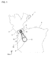
Fig. 1 is a side view of an internal combustion engine including a connecting rod according to a first embodiment of the present invention; -
Fig. 2 is a front view of a connecting rod according to the first embodiment; -
Fig. 3 is a cross-sectional view taken along line III-III inFig. 2 showing the connecting rod according to the first embodiment; -
Fig. 4 is an enlarged cross-sectional view of the part IV inFig. 3 ; -
Fig. 5 is also an enlarged cross-sectional view of the part IV inFig. 3 ; -
Fig. 6 is a sequence of enlarged cross-sectional views of the part IV inFig. 3 , illustrating the process of manufacturing the connecting rod according to the first embodiment; and -
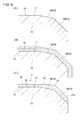
Fig. 7 is an enlarged cross-sectional view of the part IV inFig. 3 showing a connecting rod according to a second embodiment of the present invention. - Embodiments of the present invention will be described in detail below with reference to the accompanying drawings.
-
Fig. 1 is a schematic diagram of aninternal combustion engine 1 which incorporates a connectingrod 10 according to the first embodiment. Theinternal combustion engine 1 can be used in saddle-ride type vehicles such as motorcycles and the like. In the drawings, arrow FR points in the forward direction of the vehicle in normal use, while arrow UP points in the upward direction in normal use. - As shown in
Fig. 1 , apiston 3 is slidably housed in acylinder unit 2 of theinternal combustion engine 1, and acrankshaft 5 is rotatably supported in acrankcase 4 below thecylinder unit 2. Apiston pin 6 is mounted within thepiston 3 to extend along a diametrical direction of the piston. Acrankpin 8 is provided integrally with thecrankshaft 5 and eccentrically to a rotatingshaft 7 of thecrankshaft 5. In the case of the first embodiment, thepiston pin 6 constitutes a power transmitting pin. -
Fig. 2 andFig. 3 are diagrams showing the connectingrod 10. - As shown in these diagrams, the connecting
rod 10 has a smallerdiameter connecting hole 11 formed in one end, and a largerdiameter connecting hole 12 formed in the other end. Thepiston pin 6 is slidably fitted into the smallerdiameter connecting hole 11. Thecrankpin 8 is slidably fitted into the largerdiameter connecting hole 12. A principal part of the connectingrod 10 is formed from the connecting rod base material, which may be chromium-molybdenum steel, carbon steel, aluminium alloy and/or the like, by casting or forging. - The end of the connecting
rod 10 with the smallerdiameter connecting hole 11 formed in it and the other end with the largerdiameter connecting hole 12 formed in it are each formed in a generally cylindrical shape, as shown inFig. 3 . However, the generally cylindrical portion with the smallerdiameter connecting hole 11 formed in it is formed with a somewhat trapezoidal shape in cross-section, such that a proximal portion 10Eb (at the lower side inFig. 3 ) of the connectingrod 10 has a greater width in the axial direction of the connectinghole 11 than the extendedend 10E (at the upper side inFig. 3 ). Accordingly, in the smallerdiameter connecting hole 11, the load acting on thepiston 3 during engine operation, and in particular the combustion stroke, can advantageously be received on a larger area. -
Fig. 4 and Fig. 5 are enlarged cross-sectional views of part IV of the connectingrod 10 shown inFig. 3 . - These Figures show a part of the smaller
diameter connecting hole 11 of the connectingrod 10. The inner peripheral face of abase material hole 15 drilled through the connectingrod base material 14 is covered with acoating layer 16 formed of coating material by plating or the like. The coating material is softer than the connecting-rod base material 14, and may be a copper alloy or the like. - The
base material hole 15 has a constant inner diameter cylindricalinner surface portion 17, which is formed in an axially central region of the hole, and a taperedinner surface portion 18 which is continuous with the axially outer end of the cylindricalinner surface portion 17 and is radially enlarged in the axially outward direction (such that the end of thehole 15 is flared).Fig. 4 and Fig. 5 only show a part of one axial end of the base material hole 15 (the right side inFig. 3 ), but it will be understood that the other axial end of the base material hole 15 (the left side inFig. 3 ) is of the same structure. - The tapered
inner surface portion 18 of thebase material hole 15 includes a firsttapered portion 18A and a secondtapered portion 18B, so that the taper angle is changed in a plurality of stages (more specifically, in the first embodiment, two stages). The firsttapered portion 18A is arranged adjacent to the axially outer side of the cylindricalinner surface portion 17, and the secondtapered portion 18B is arranged adjacent to the axially outer side of the firsttapered portion 18A. The angle θ1 which the cylindricalinner surface portion 17 forms with the firsttapered portion 18A is set to be greater than the angle θ2 which the firsttapered portion 18A forms with the secondtapered portion 18B. Therefore, the taperedinner surface portion 18 of thebase material hole 15 is set so that the diameter expansion rate in the axially inner region is lower than the diameter expansion rate in the axially outer region. In the first embodiment, the taperedinner surface portion 18 of thebase material hole 15 is formed of a tapered surface with a plurality of stages (two stages), so that the taper angle is changed in a number of separate stages. - In the first embodiment, the second
tapered portion 18B of the taperedinner surface portion 18 is formed by chamfering, in a tapering manner, a part of the peripheral edge of the connecting hole 11 (a lower edge region inFig. 2 ) on an axial end face 10Es of the extendedend 10E (at the top end of the rod inFig. 2 ) of the connectingrod 10 on the connectinghole 11 side, as illustrated inFig. 2 .Reference numeral 40 inFig. 2 denotes the chamfered portion. - However, the second
tapered portion 18B may be formed around the entire peripheral edge of the connectinghole 11 on the axial end face 10Es of the extendedend 10E of the connectingrod 10 on the connectinghole 11 side. - The
coating layer 16 has: afirst coating portion 19 applied to the cylindricalinner surface portion 17, such that the inner surface has an approximately constant inner diameter; asecond coating portion 20 applied to the taperedinner surface portion 18 and having a region which is contiguous with thefirst coating portion 19 and gradually increasing in material thickness in the axially outward direction of the hole; and athird coating portion 21 continuous with the axially outer side of thesecond coating portion 20, applied to the taperedinner surface portion 18 which is radially enlarged in the axially outward direction. In the case of the first embodiment, in thethird coating portion 21, the inner peripheral surface is radially enlarged in two stages in the axially outward direction.Reference numeral 21 a in the drawings denotes a stepped coating portion in which the inner peripheral face is radially enlarged gradually in the axially outer region of thethird coating portion 21. - Note that the
third coating portion 21, which is continuous with the axial outer side of thesecond coating portion 20, is formed to have an approximately constant material thickness over the entire range. Thethird coating portion 21 is applied to lie astride the firsttapered portion 18A and the secondtapered portion 18B of the taperedinner surface portion 18 of thebase material hole 15. Therefore, while having an approximately constant thickness, thethird coating portion 21 has an inner peripheral face which is gradually radially enlarged in the axially outward direction. - An example of how to machine the connecting
hole 11 in the connectingrod 10 according to the first embodiment will now be described with reference toFig. 6 . - First, the connecting
rod base material 14 is shaped by casting or forging, and then the inner surface of thebase material hole 15 is machined by cutting, grinding or the like. In this stage, as illustrated inFig. 6(A) , the cylindricalinner surface portion 17 and the tapered inner surface portion 18 (the firsttapered portion 18A and the secondtapered portion 18B) are formed in thebase material hole 15. - Then, after the machining described above, the coating material is deposited on the
base material hole 15 by plating or the like, so as to have an approximately uniform thickness as illustrated inFig. 6(B) . - Then, the inner surface of the area coated with the coating material is subjected to removal machining, such as honing or the like, so that the inner surface is made approximately parallel to the cylindrical
inner surface portion 17 of thebase material hole 15. Thus, a predetermined thickness of the coating material deposited is removed from an axially central region of the area coated with the coating material. As a result, the portion of the coating material covering the cylindricalinner surface portion 17 has an approximately uniform thickness, while a portion of the coating material covering the taperedinner surface portion 18 includes a portion gradually increasing in material thickness in the axially outward direction, beginning with the point adjacent to the cylindricalinner surface portion 17. The portion with uniform thickness covering the cylindricalinner surface portion 17 serves as thefirst coating portion 19, and the portion which gradually increases in material thickness beginning with the point adjacent to the cylindricalinner surface portion 17 serves as thesecond coating portion 20. The unremoved portion of the coating material deposited on the taperedinner surface portion 18 serves as thethird coating portion 21. - As described above, in the connecting
rod 10 according to the first embodiment, the coating material (which is softer than the connecting rod base material 14) is deposited on the taperedinner surface portion 18 of thebase material hole 15, and the material thickness of the coating material in thesecond coating portion 20 adjoining thefirst coating portion 19 gradually increases in the axially outward direction. For this reason, when the connectingrod 10 according to the first embodiment is used in aninternal combustion engine 1, an efficient reduction in contact pressure acting on thepiston pin 6 from the portion around the axially outer end of the connectinghole 11 can be achieved. - When a load acting on the
piston pin 6 from thepiston 3 increases, as a result of the combustion stroke during the operation of theinternal combustion engine 1, this causes the axial end of thepiston pin 6 to bend largely in the up-and-down direction (if the cylinder is considered to be vertical), and typically, as a result of the bending, the contact pressure acting on thepiston pin 6 tends to be increasingly larger closer to the axially outermost region of the connectinghole 11. However, in the connectingrod 10 according to the first embodiment, the taperedinner surface portion 18 which is radially enlarged in the axially outward direction is formed in a position outside the cylindricalinner surface portion 17 of thebase material hole 15. Further, the coating material, which is softer than the connectingrod base material 14, is deposited on the cylindricalinner surface portion 17 and the taperedinner surface portion 18, and the material thickness of thesecond coating portion 20 deposited on the taperedinner surface portion 18 gradually increases toward the outside in the axial direction. As a result, in the further axially outward regions of the connectinghole 11 where the contact pressure is easily increased by the bending of thepiston pin 6, the cushioning effect of the coating material can be enhanced. Accordingly, in the connectingrod 10, an efficient reduction in contact pressure acting on thepiston pin 6 from the region around the axially outer end of the connectinghole 11 is made possible. - Further, in the connecting
rod 10 according to the first embodiment, thesecond coating portion 20 deposited on the taperedinner surface portion 18 is formed continuously with thefirst coating portion 19 so as to have an approximately constant inner diameter. Because of this, when the bending of thepiston pin 6 is small, thepiston pin 6 is supported across a wide extent of thefirst coating portion 19 and thesecond coating portion 20. Accordingly, by employing the connectingrod 10 according to the first embodiment, even when the bending of thepiston pin 6 is small, the contact area between thepiston pin 6 and the connectinghole 11 can be increased for an improvement in wear resistance property. - Further, in the connecting
rod 10 according to the first embodiment, because the continuous inner peripheral face with the constant inner diameter of thefirst coating portion 19 and thesecond coating portion 20 is machined by honing and/or the like to remove material, the inner peripheral surface of thefirst coating portion 19 and thesecond coating portion 20 can be formed as a continuous approximately constant inner diameter surface with ease and accuracy. - Further, in the first embodiment, the
third coating portion 21 is provided in a position axially outward of thesecond coating portion 20 of thecoating layer 16 and has an inner peripheral face which is radially enlarged in the axially outward direction. Because of this, when thepiston pin 6 largely bends in the up-and-down direction of the cylinder, a wider extent of thecoating layer 16 is made to readily follow the bending of thepiston pin 6. Therefore, in the first embodiment, a further advantageous reduction in contact pressure acting on thepiston pin 6 from the edge of the connectinghole 11 when a large load is applied is made possible. - Further, in the connecting
rod 10 according to the first embodiment, thesecond coating portion 20 which gradually increases in material thickness is placed outside and continuously with thefirst coating portion 19 of thecoating layer 16 in the axial direction, and thethird coating portion 21 with an approximately constant material thickness is placed outside and continuously with thesecond coating portion 20 in the axial direction, in such a way that the inner peripheral face is gradually radially enlarged. Because of this, as illustrated inFig. 5 , when thepiston pin 6 is acted upon by a load during the combustion stroke and thus bends to a larger degree, at the beginning of the bending the amount of elastic deformation increases by degree in thesecond coating portion 20 with gradually increasing material thickness. Then, the amount of elastic deformation decreases bit by bit in thethird coating portion 21 with an approximately constant thickness and the inner peripheral face radially enlarged in a stepwise manner. Accordingly, by employing the connectingrod 10 according to the first embodiment, changes in contact pressure applied to thepiston pin 6 can be made gradual, resulting in further advantage in wear resistance of thepiston pin 6. - Further, in the connecting
rod 10 according to the first embodiment, the diameter expansion rate in the axially outer region of the taperedinner surface portion 18 is set to be larger than the diameter expansion rate in the axially inner region of the taperedinner surface portion 18. Because of this, thethird coating portion 21 with the inner peripheral surface radially enlarged toward the outside in the axial direction can be readily formed by uniformly depositing the coating material on the taperedinner surface portion 18. - Further, in the case of the connecting
rod 10 according to the first embodiment, the taperedinner surface portion 18 is formed of a tapered surface with a plurality of stages, in which the taper angle is changed in multiple separate stages. Because of this, the taperedinner surface portion 18 with varying diameter expansion rate can be easily formed by removal machining such as cutting and/or the like. - Further, in the connecting
rod 10 according to the first embodiment, the taperedinner surface portion 18 has the firsttapered portion 18A which is arranged adjacent to the axially outer side of the cylindricalinner surface portion 17, and the secondtapered portion 18B which is arranged adjacent to the axially outer side of the firsttapered portion 18A. Further, the angle θ1 which the cylindricalinner surface portion 17 forms with the firsttapered portion 18A is set to be greater than the angle θ2 which the firsttapered portion 18A forms with the secondtapered portion 18B. As a result, in the first embodiment, when thepiston pin 6 is subjected to a large load and made to bend, thepiston pin 6 is less subject to large contact pressure from the region around the axial end of the connectinghole 11. - In this regard, the angle θ2 which the first
tapered portion 18A forms with the secondtapered portion 18B is desirably an obtuse angle. In this case, as shown inFig. 5 , when thepiston pin 6 bends to come into contact with thethird coating portion 21, the contact pressure acting on thepiston pin 6 does not easily increase to be higher. The angle θ2 which the firsttapered portion 18A forms with the secondtapered portion 18B is desirably equal to or greater than 135 degrees. - Further, in the first embodiment, chamfering is performed on a part of the peripheral edge of the connecting
hole 11 on the axial end face 10Es of theextended end 10E on the connectinghole 11 side of the connectingrod 10 so that the secondtapered portion 18B is formed on the part of the peripheral edge by the chamfering (the chamfered portion 40). By forming the secondtapered portion 18B in this manner, the secondtapered portion 18B can be readily formed without sophisticated machining. - It should be understood that the present invention is not limited to the aforementioned embodiment and various changes in design can be made without departing from the invention.
- For example, in the first embodiment, the tapered
inner surface portion 18 arranged adjacent to the cylindricalinner surface portion 17 of thebase material hole 15 is formed in a bent manner so as to be radially enlarged toward the outside in the axial direction. However, in another embodiment illustrated inFig. 7 , a taperedinner surface portion 118 may be curved in an arc shape such that an angle change occurs smoothly from the cylindricalinner surface portion 17.
Claims (7)
- A connecting rod for an internal combustion engine, comprising:a connecting hole (11) through which a power transmitting pin (6) is slidably fitted,the connecting hole (11) being formed by coating an inner peripheral surface of a base material hole (15) formed in a connecting rod base material (14) with a coating material which is softer than the connecting rod base material (14),wherein the base material hole (15) includes:a cylindrical inner surface portion (17) with a constant inner diameter, formed in an axially central region; anda tapered inner surface portion (18) that is continuous with an axially outer side of the cylindrical inner surface portion (17) and is radially enlarged in an axially outward direction, andwherein the coating layer (16) formed from the coating material includes:a first coating portion (19) deposited on the cylindrical inner surface portion (17) and having an inner face with an approximately constant inner diameter; anda second coating portion (20) deposited on the tapered inner surface portion (18) to adjoin the first coating portion (19) and gradually increasing in material thickness in the axially outward direction.
- The connecting rod for an internal combustion engine according to claim 1, wherein an inner peripheral face of the second coating portion (20) is formed continuously with an inner peripheral face of the first coating portion (19) so as to have an approximately constant inner diameter.
- The connecting rod for an internal combustion engine according to claim 2, wherein the continuous inner peripheral face of the first coating portion (19) and the second coating portion (20) are formed by machining to remove part of the coating material.
- The connecting rod for an internal combustion engine according to any one of claims 1 to 3, wherein the coating layer (16) includes a third coating portion (21) continuous with an axially outward side of the second coating portion (20) and having an inner peripheral face radially enlarged in the axially outward direction.
- The connecting rod for an internal combustion engine according to any preceding claim, wherein the tapered inner surface portion (18) of the base material hole (15) has a diameter expansion rate in an axially outer region which is larger than a diameter expansion rate in an axially inner region.
- The connecting rod for an internal combustion engine according to claim 5, wherein the tapered inner surface portion (18) of the base material hole (15) is formed as a tapered surface with a plurality of stages, in which the taper angle is changed in multiple separate stages.
- The connecting rod for an internal combustion engine according to claim 6, wherein:the tapered inner surface portion (18) of the base material hole (15) has a first tapered portion (18A) arranged adjacent to an axially outer side of the cylindrical inner surface portion (17), and a second tapered portion (18B) arranged adjacent to an axially outer side of the first tapered portion (18A); andwherein an angle which the cylindrical inner surface portion (17) forms with the first tapered portion (18A) is set to be greater than an angle which the first tapered portion (18A) forms with the second tapered portion (18B).
Applications Claiming Priority (1)
| Application Number | Priority Date | Filing Date | Title |
|---|---|---|---|
| JP2014197141A JP2016070297A (en) | 2014-09-26 | 2014-09-26 | Connecting rod of internal combustion engine |
Publications (2)
| Publication Number | Publication Date |
|---|---|
| EP3029342A1 true EP3029342A1 (en) | 2016-06-08 |
| EP3029342B1 EP3029342B1 (en) | 2017-11-15 |
Family
ID=53969095
Family Applications (1)
| Application Number | Title | Priority Date | Filing Date |
|---|---|---|---|
| EP15177841.2A Not-in-force EP3029342B1 (en) | 2014-09-26 | 2015-07-22 | Connecting rod for internal combustion engine |
Country Status (7)
| Country | Link |
|---|---|
| US (1) | US9862021B2 (en) |
| EP (1) | EP3029342B1 (en) |
| JP (1) | JP2016070297A (en) |
| CN (1) | CN105465159B (en) |
| AU (1) | AU2015204340B2 (en) |
| CA (1) | CA2900069C (en) |
| ES (1) | ES2651897T3 (en) |
Cited By (1)
| Publication number | Priority date | Publication date | Assignee | Title |
|---|---|---|---|---|
| EP3306124A4 (en) * | 2015-06-01 | 2018-12-05 | Taiho Kogyo Co., Ltd | Bearing for internal combustion engine and production method for bearing for internal combustion engine |
Families Citing this family (3)
| Publication number | Priority date | Publication date | Assignee | Title |
|---|---|---|---|---|
| US10578150B2 (en) * | 2018-07-24 | 2020-03-03 | GM Global Technology Operations LLC | Combustion engine connecting rod |
| JP6804577B2 (en) * | 2019-02-08 | 2020-12-23 | 大同メタル工業株式会社 | Half-thrust bearing for crankshaft of internal combustion engine |
| JP6811810B2 (en) * | 2019-06-26 | 2021-01-13 | 本田技研工業株式会社 | Slide bearing structure and vehicle rear toe control device. |
Citations (5)
| Publication number | Priority date | Publication date | Assignee | Title |
|---|---|---|---|---|
| GB2218752A (en) * | 1988-05-13 | 1989-11-22 | Mtu Friedrichshafen Gmbh | A three-component plain bearing |
| WO2000034696A1 (en) * | 1998-12-11 | 2000-06-15 | Cummins Engine Company, Inc. | Connecting rod with profiled bore for increased load capability |
| JP2001511500A (en) | 1997-07-28 | 2001-08-14 | フオルクスワーゲン・アクチエンゲゼルシヤフト | Connecting rod with bearing metal |
| DE102006013399A1 (en) * | 2005-12-21 | 2007-07-05 | Mahle International Gmbh | Connecting rod for internal combustion engine, has small connecting rod eye for holding piston pin and large connecting rod eye for holding crank pin whereby bore is provided with coating having resin with solid lubricant particles |
| WO2014126202A1 (en) * | 2013-02-15 | 2014-08-21 | 大豊工業株式会社 | Sliding member |
Family Cites Families (15)
| Publication number | Priority date | Publication date | Assignee | Title |
|---|---|---|---|---|
| JPS60134962U (en) * | 1984-02-21 | 1985-09-07 | マツダ株式会社 | Structure of piston conrod |
| JPH0579036U (en) * | 1992-03-31 | 1993-10-26 | いすゞ自動車株式会社 | Internal combustion engine connecting rod |
| JPH07158630A (en) * | 1993-12-03 | 1995-06-20 | Toyota Motor Corp | Connecting rod |
| JPH094463A (en) * | 1995-06-19 | 1997-01-07 | Yanmar Diesel Engine Co Ltd | Engine |
| JP3388501B2 (en) * | 1998-06-29 | 2003-03-24 | 大同メタル工業株式会社 | Plain bearing |
| US20020157534A1 (en) * | 2001-04-25 | 2002-10-31 | Deere & Company, A Delaware Corporation | Connecting rod bore profile for bushingless piston assembly |
| AT412556B (en) * | 2002-10-04 | 2005-04-25 | Miba Gleitlager Gmbh | METHOD FOR MANUFACTURING AT LEAST ONE LAGERAUGEWICHEN WORKPIECE |
| US6923153B2 (en) * | 2003-06-26 | 2005-08-02 | Mahle Technology, Inc. | Piston and connecting rod assembly having phosphatized bushingless connecting rod and profiled piston pin |
| US8613137B2 (en) * | 2004-11-16 | 2013-12-24 | Mahle International Gmbh | Connecting rod lubrication recess |
| US7581315B2 (en) * | 2004-11-16 | 2009-09-01 | Mahle Technology, Inc. | Connecting rod assembly for an internal combustion engine and method of manufacturing same |
| US8539928B2 (en) * | 2007-12-10 | 2013-09-24 | Federal-Mogul World Wide, Inc. | Piston assembly and connecting rod having a profiled wrist pin bore therefor |
| US8245687B2 (en) * | 2010-01-07 | 2012-08-21 | Mahle International Gmbh | Profiled connecting rod bore with micro-dimples |
| US8893580B2 (en) * | 2011-10-17 | 2014-11-25 | Mahle International Gmbh | Thermal spray coating for connecting rod small end |
| JP2013245767A (en) * | 2012-05-25 | 2013-12-09 | Taiho Kogyo Co Ltd | Sliding bearing |
| JP6195053B2 (en) * | 2013-03-13 | 2017-09-13 | 大豊工業株式会社 | Half thrust bearing and manufacturing method thereof |
-
2014
- 2014-09-26 JP JP2014197141A patent/JP2016070297A/en active Pending
-
2015
- 2015-07-16 AU AU2015204340A patent/AU2015204340B2/en not_active Ceased
- 2015-07-22 EP EP15177841.2A patent/EP3029342B1/en not_active Not-in-force
- 2015-07-22 ES ES15177841.2T patent/ES2651897T3/en active Active
- 2015-08-10 CA CA2900069A patent/CA2900069C/en not_active Expired - Fee Related
- 2015-08-31 US US14/840,145 patent/US9862021B2/en not_active Expired - Fee Related
- 2015-09-22 CN CN201510609256.7A patent/CN105465159B/en not_active Expired - Fee Related
Patent Citations (5)
| Publication number | Priority date | Publication date | Assignee | Title |
|---|---|---|---|---|
| GB2218752A (en) * | 1988-05-13 | 1989-11-22 | Mtu Friedrichshafen Gmbh | A three-component plain bearing |
| JP2001511500A (en) | 1997-07-28 | 2001-08-14 | フオルクスワーゲン・アクチエンゲゼルシヤフト | Connecting rod with bearing metal |
| WO2000034696A1 (en) * | 1998-12-11 | 2000-06-15 | Cummins Engine Company, Inc. | Connecting rod with profiled bore for increased load capability |
| DE102006013399A1 (en) * | 2005-12-21 | 2007-07-05 | Mahle International Gmbh | Connecting rod for internal combustion engine, has small connecting rod eye for holding piston pin and large connecting rod eye for holding crank pin whereby bore is provided with coating having resin with solid lubricant particles |
| WO2014126202A1 (en) * | 2013-02-15 | 2014-08-21 | 大豊工業株式会社 | Sliding member |
Cited By (2)
| Publication number | Priority date | Publication date | Assignee | Title |
|---|---|---|---|---|
| EP3306124A4 (en) * | 2015-06-01 | 2018-12-05 | Taiho Kogyo Co., Ltd | Bearing for internal combustion engine and production method for bearing for internal combustion engine |
| US10228014B2 (en) | 2015-06-01 | 2019-03-12 | Taiho Kogyo Co., Ltd. | Internal combustion engine bearing and method of manufacturing internal combustion engine bearing |
Also Published As
| Publication number | Publication date |
|---|---|
| JP2016070297A (en) | 2016-05-09 |
| CN105465159B (en) | 2018-06-15 |
| AU2015204340A1 (en) | 2016-04-14 |
| AU2015204340B2 (en) | 2016-11-17 |
| ES2651897T3 (en) | 2018-01-30 |
| US9862021B2 (en) | 2018-01-09 |
| US20160091013A1 (en) | 2016-03-31 |
| CA2900069C (en) | 2016-08-16 |
| CN105465159A (en) | 2016-04-06 |
| CA2900069A1 (en) | 2016-03-26 |
| EP3029342B1 (en) | 2017-11-15 |
Similar Documents
| Publication | Publication Date | Title |
|---|---|---|
| EP3029342B1 (en) | Connecting rod for internal combustion engine | |
| EP3015204B1 (en) | Production method for titanium-alloy connecting rod | |
| JP5599390B2 (en) | Multi-blade drilling tool | |
| JP5773500B2 (en) | Oil ring for internal combustion engine | |
| EP2438315B1 (en) | Connecting rod lubrication recess | |
| JP5116980B2 (en) | Tool and method for generating threads | |
| JP2010038021A (en) | Spring retainer and spring system | |
| CN103732932A (en) | Sliding member, plain half bearing using same, and manufacturing method for plain half bearing | |
| US10961947B2 (en) | Cylinder liner | |
| US20130276741A1 (en) | Bearing bushing for a connecting rod, combination of a connecting rod and a bearing bushing, and method for producing same | |
| CN206035657U (en) | Internal -combustion engine of cylinder crankcase with casting | |
| JP6894879B2 (en) | Internal combustion engine cylinder and manufacturing method | |
| JP2011220150A (en) | Cylinder bore and method for manufacturing the same | |
| US10161438B2 (en) | Connecting rod | |
| EP3015723B1 (en) | Connecting rod, internal combustion engine, automotive vehicle, and production method for connecting rod | |
| EP2711567B1 (en) | Weight optimized crank-shaft | |
| US10823224B2 (en) | Bearing member, housing, and bearing device using the same | |
| DE3743816A1 (en) | Cam for a built camshaft of a reciprocating internal-combustion engine | |
| EP3871800B1 (en) | Method of manufacturing intermediate product with engine valve boss portion | |
| US10982573B2 (en) | Method for mounting a valve seat ring on a cylinder head of an internal combustion engine | |
| EP3521644A1 (en) | Crankshaft with concavely curved crank pins | |
| EP3015722B1 (en) | Connecting rod, internal combustion engine and automotive vehicle | |
| JP6457368B2 (en) | Engine bearing structure | |
| JP2016123978A (en) | Method for manufacturing forged crank shaft | |
| CN105624933A (en) | Feeding tooth lifting fork for sewing machine |
Legal Events
| Date | Code | Title | Description |
|---|---|---|---|
| PUAI | Public reference made under article 153(3) epc to a published international application that has entered the european phase |
Free format text: ORIGINAL CODE: 0009012 |
|
| 17P | Request for examination filed |
Effective date: 20150722 |
|
| AK | Designated contracting states |
Kind code of ref document: A1 Designated state(s): AL AT BE BG CH CY CZ DE DK EE ES FI FR GB GR HR HU IE IS IT LI LT LU LV MC MK MT NL NO PL PT RO RS SE SI SK SM TR |
|
| AX | Request for extension of the european patent |
Extension state: BA ME |
|
| RIC1 | Information provided on ipc code assigned before grant |
Ipc: F16C 23/04 20060101ALI20170301BHEP Ipc: F16C 9/04 20060101AFI20170301BHEP |
|
| GRAP | Despatch of communication of intention to grant a patent |
Free format text: ORIGINAL CODE: EPIDOSNIGR1 |
|
| INTG | Intention to grant announced |
Effective date: 20170524 |
|
| RAP1 | Party data changed (applicant data changed or rights of an application transferred) |
Owner name: HONDA MOTOR CO., LTD. |
|
| GRAS | Grant fee paid |
Free format text: ORIGINAL CODE: EPIDOSNIGR3 |
|
| GRAA | (expected) grant |
Free format text: ORIGINAL CODE: 0009210 |
|
| AK | Designated contracting states |
Kind code of ref document: B1 Designated state(s): AL AT BE BG CH CY CZ DE DK EE ES FI FR GB GR HR HU IE IS IT LI LT LU LV MC MK MT NL NO PL PT RO RS SE SI SK SM TR |
|
| REG | Reference to a national code |
Ref country code: CH Ref legal event code: EP Ref country code: GB Ref legal event code: FG4D Ref country code: AT Ref legal event code: REF Ref document number: 946593 Country of ref document: AT Kind code of ref document: T Effective date: 20171115 |
|
| REG | Reference to a national code |
Ref country code: IE Ref legal event code: FG4D |
|
| REG | Reference to a national code |
Ref country code: DE Ref legal event code: R096 Ref document number: 602015005973 Country of ref document: DE |
|
| REG | Reference to a national code |
Ref country code: ES Ref legal event code: FG2A Ref document number: 2651897 Country of ref document: ES Kind code of ref document: T3 Effective date: 20180130 |
|
| REG | Reference to a national code |
Ref country code: NL Ref legal event code: MP Effective date: 20171115 |
|
| REG | Reference to a national code |
Ref country code: LT Ref legal event code: MG4D |
|
| REG | Reference to a national code |
Ref country code: AT Ref legal event code: MK05 Ref document number: 946593 Country of ref document: AT Kind code of ref document: T Effective date: 20171115 |
|
| PG25 | Lapsed in a contracting state [announced via postgrant information from national office to epo] |
Ref country code: FI Free format text: LAPSE BECAUSE OF FAILURE TO SUBMIT A TRANSLATION OF THE DESCRIPTION OR TO PAY THE FEE WITHIN THE PRESCRIBED TIME-LIMIT Effective date: 20171115 Ref country code: NL Free format text: LAPSE BECAUSE OF FAILURE TO SUBMIT A TRANSLATION OF THE DESCRIPTION OR TO PAY THE FEE WITHIN THE PRESCRIBED TIME-LIMIT Effective date: 20171115 Ref country code: NO Free format text: LAPSE BECAUSE OF FAILURE TO SUBMIT A TRANSLATION OF THE DESCRIPTION OR TO PAY THE FEE WITHIN THE PRESCRIBED TIME-LIMIT Effective date: 20180215 Ref country code: LT Free format text: LAPSE BECAUSE OF FAILURE TO SUBMIT A TRANSLATION OF THE DESCRIPTION OR TO PAY THE FEE WITHIN THE PRESCRIBED TIME-LIMIT Effective date: 20171115 Ref country code: SE Free format text: LAPSE BECAUSE OF FAILURE TO SUBMIT A TRANSLATION OF THE DESCRIPTION OR TO PAY THE FEE WITHIN THE PRESCRIBED TIME-LIMIT Effective date: 20171115 |
|
| PG25 | Lapsed in a contracting state [announced via postgrant information from national office to epo] |
Ref country code: BG Free format text: LAPSE BECAUSE OF FAILURE TO SUBMIT A TRANSLATION OF THE DESCRIPTION OR TO PAY THE FEE WITHIN THE PRESCRIBED TIME-LIMIT Effective date: 20180215 Ref country code: HR Free format text: LAPSE BECAUSE OF FAILURE TO SUBMIT A TRANSLATION OF THE DESCRIPTION OR TO PAY THE FEE WITHIN THE PRESCRIBED TIME-LIMIT Effective date: 20171115 Ref country code: LV Free format text: LAPSE BECAUSE OF FAILURE TO SUBMIT A TRANSLATION OF THE DESCRIPTION OR TO PAY THE FEE WITHIN THE PRESCRIBED TIME-LIMIT Effective date: 20171115 Ref country code: GR Free format text: LAPSE BECAUSE OF FAILURE TO SUBMIT A TRANSLATION OF THE DESCRIPTION OR TO PAY THE FEE WITHIN THE PRESCRIBED TIME-LIMIT Effective date: 20180216 Ref country code: AT Free format text: LAPSE BECAUSE OF FAILURE TO SUBMIT A TRANSLATION OF THE DESCRIPTION OR TO PAY THE FEE WITHIN THE PRESCRIBED TIME-LIMIT Effective date: 20171115 Ref country code: RS Free format text: LAPSE BECAUSE OF FAILURE TO SUBMIT A TRANSLATION OF THE DESCRIPTION OR TO PAY THE FEE WITHIN THE PRESCRIBED TIME-LIMIT Effective date: 20171115 |
|
| REG | Reference to a national code |
Ref country code: FR Ref legal event code: PLFP Year of fee payment: 4 |
|
| PG25 | Lapsed in a contracting state [announced via postgrant information from national office to epo] |
Ref country code: SK Free format text: LAPSE BECAUSE OF FAILURE TO SUBMIT A TRANSLATION OF THE DESCRIPTION OR TO PAY THE FEE WITHIN THE PRESCRIBED TIME-LIMIT Effective date: 20171115 Ref country code: CY Free format text: LAPSE BECAUSE OF FAILURE TO SUBMIT A TRANSLATION OF THE DESCRIPTION OR TO PAY THE FEE WITHIN THE PRESCRIBED TIME-LIMIT Effective date: 20171115 Ref country code: EE Free format text: LAPSE BECAUSE OF FAILURE TO SUBMIT A TRANSLATION OF THE DESCRIPTION OR TO PAY THE FEE WITHIN THE PRESCRIBED TIME-LIMIT Effective date: 20171115 Ref country code: CZ Free format text: LAPSE BECAUSE OF FAILURE TO SUBMIT A TRANSLATION OF THE DESCRIPTION OR TO PAY THE FEE WITHIN THE PRESCRIBED TIME-LIMIT Effective date: 20171115 Ref country code: DK Free format text: LAPSE BECAUSE OF FAILURE TO SUBMIT A TRANSLATION OF THE DESCRIPTION OR TO PAY THE FEE WITHIN THE PRESCRIBED TIME-LIMIT Effective date: 20171115 |
|
| REG | Reference to a national code |
Ref country code: DE Ref legal event code: R097 Ref document number: 602015005973 Country of ref document: DE |
|
| PG25 | Lapsed in a contracting state [announced via postgrant information from national office to epo] |
Ref country code: SM Free format text: LAPSE BECAUSE OF FAILURE TO SUBMIT A TRANSLATION OF THE DESCRIPTION OR TO PAY THE FEE WITHIN THE PRESCRIBED TIME-LIMIT Effective date: 20171115 Ref country code: PL Free format text: LAPSE BECAUSE OF FAILURE TO SUBMIT A TRANSLATION OF THE DESCRIPTION OR TO PAY THE FEE WITHIN THE PRESCRIBED TIME-LIMIT Effective date: 20171115 Ref country code: RO Free format text: LAPSE BECAUSE OF FAILURE TO SUBMIT A TRANSLATION OF THE DESCRIPTION OR TO PAY THE FEE WITHIN THE PRESCRIBED TIME-LIMIT Effective date: 20171115 |
|
| PLBE | No opposition filed within time limit |
Free format text: ORIGINAL CODE: 0009261 |
|
| STAA | Information on the status of an ep patent application or granted ep patent |
Free format text: STATUS: NO OPPOSITION FILED WITHIN TIME LIMIT |
|
| 26N | No opposition filed |
Effective date: 20180817 |
|
| PGFP | Annual fee paid to national office [announced via postgrant information from national office to epo] |
Ref country code: FR Payment date: 20180720 Year of fee payment: 4 Ref country code: ES Payment date: 20180802 Year of fee payment: 4 Ref country code: IT Payment date: 20180731 Year of fee payment: 4 Ref country code: DE Payment date: 20180718 Year of fee payment: 4 |
|
| PG25 | Lapsed in a contracting state [announced via postgrant information from national office to epo] |
Ref country code: SI Free format text: LAPSE BECAUSE OF FAILURE TO SUBMIT A TRANSLATION OF THE DESCRIPTION OR TO PAY THE FEE WITHIN THE PRESCRIBED TIME-LIMIT Effective date: 20171115 |
|
| REG | Reference to a national code |
Ref country code: CH Ref legal event code: PL |
|
| PG25 | Lapsed in a contracting state [announced via postgrant information from national office to epo] |
Ref country code: LU Free format text: LAPSE BECAUSE OF NON-PAYMENT OF DUE FEES Effective date: 20180722 Ref country code: MC Free format text: LAPSE BECAUSE OF FAILURE TO SUBMIT A TRANSLATION OF THE DESCRIPTION OR TO PAY THE FEE WITHIN THE PRESCRIBED TIME-LIMIT Effective date: 20171115 |
|
| REG | Reference to a national code |
Ref country code: BE Ref legal event code: MM Effective date: 20180731 |
|
| REG | Reference to a national code |
Ref country code: IE Ref legal event code: MM4A |
|
| PG25 | Lapsed in a contracting state [announced via postgrant information from national office to epo] |
Ref country code: IE Free format text: LAPSE BECAUSE OF NON-PAYMENT OF DUE FEES Effective date: 20180722 Ref country code: LI Free format text: LAPSE BECAUSE OF NON-PAYMENT OF DUE FEES Effective date: 20180731 Ref country code: CH Free format text: LAPSE BECAUSE OF NON-PAYMENT OF DUE FEES Effective date: 20180731 |
|
| PG25 | Lapsed in a contracting state [announced via postgrant information from national office to epo] |
Ref country code: BE Free format text: LAPSE BECAUSE OF NON-PAYMENT OF DUE FEES Effective date: 20180731 |
|
| PG25 | Lapsed in a contracting state [announced via postgrant information from national office to epo] |
Ref country code: MT Free format text: LAPSE BECAUSE OF NON-PAYMENT OF DUE FEES Effective date: 20180722 |
|
| REG | Reference to a national code |
Ref country code: DE Ref legal event code: R119 Ref document number: 602015005973 Country of ref document: DE |
|
| GBPC | Gb: european patent ceased through non-payment of renewal fee |
Effective date: 20190722 |
|
| PG25 | Lapsed in a contracting state [announced via postgrant information from national office to epo] |
Ref country code: TR Free format text: LAPSE BECAUSE OF FAILURE TO SUBMIT A TRANSLATION OF THE DESCRIPTION OR TO PAY THE FEE WITHIN THE PRESCRIBED TIME-LIMIT Effective date: 20171115 |
|
| PG25 | Lapsed in a contracting state [announced via postgrant information from national office to epo] |
Ref country code: DE Free format text: LAPSE BECAUSE OF NON-PAYMENT OF DUE FEES Effective date: 20200201 Ref country code: GB Free format text: LAPSE BECAUSE OF NON-PAYMENT OF DUE FEES Effective date: 20190722 |
|
| PG25 | Lapsed in a contracting state [announced via postgrant information from national office to epo] |
Ref country code: PT Free format text: LAPSE BECAUSE OF FAILURE TO SUBMIT A TRANSLATION OF THE DESCRIPTION OR TO PAY THE FEE WITHIN THE PRESCRIBED TIME-LIMIT Effective date: 20171115 |
|
| PG25 | Lapsed in a contracting state [announced via postgrant information from national office to epo] |
Ref country code: FR Free format text: LAPSE BECAUSE OF NON-PAYMENT OF DUE FEES Effective date: 20190731 Ref country code: MK Free format text: LAPSE BECAUSE OF NON-PAYMENT OF DUE FEES Effective date: 20171115 Ref country code: HU Free format text: LAPSE BECAUSE OF FAILURE TO SUBMIT A TRANSLATION OF THE DESCRIPTION OR TO PAY THE FEE WITHIN THE PRESCRIBED TIME-LIMIT; INVALID AB INITIO Effective date: 20150722 |
|
| PG25 | Lapsed in a contracting state [announced via postgrant information from national office to epo] |
Ref country code: AL Free format text: LAPSE BECAUSE OF FAILURE TO SUBMIT A TRANSLATION OF THE DESCRIPTION OR TO PAY THE FEE WITHIN THE PRESCRIBED TIME-LIMIT Effective date: 20171115 Ref country code: IS Free format text: LAPSE BECAUSE OF FAILURE TO SUBMIT A TRANSLATION OF THE DESCRIPTION OR TO PAY THE FEE WITHIN THE PRESCRIBED TIME-LIMIT Effective date: 20180315 |
|
| PG25 | Lapsed in a contracting state [announced via postgrant information from national office to epo] |
Ref country code: IT Free format text: LAPSE BECAUSE OF NON-PAYMENT OF DUE FEES Effective date: 20190722 |
|
| REG | Reference to a national code |
Ref country code: ES Ref legal event code: FD2A Effective date: 20201126 |
|
| PG25 | Lapsed in a contracting state [announced via postgrant information from national office to epo] |
Ref country code: ES Free format text: LAPSE BECAUSE OF NON-PAYMENT OF DUE FEES Effective date: 20190723 |