WO2014125935A1 - カラーフィルタの製造方法、並びにこれを用いて製造されるカラーフィルタ、固体撮像素子、及び液晶表示装置 - Google Patents
カラーフィルタの製造方法、並びにこれを用いて製造されるカラーフィルタ、固体撮像素子、及び液晶表示装置 Download PDFInfo
- Publication number
- WO2014125935A1 WO2014125935A1 PCT/JP2014/052153 JP2014052153W WO2014125935A1 WO 2014125935 A1 WO2014125935 A1 WO 2014125935A1 JP 2014052153 W JP2014052153 W JP 2014052153W WO 2014125935 A1 WO2014125935 A1 WO 2014125935A1
- Authority
- WO
- WIPO (PCT)
- Prior art keywords
- color filter
- exposure
- pattern
- present
- colored layer
- Prior art date
- Legal status (The legal status is an assumption and is not a legal conclusion. Google has not performed a legal analysis and makes no representation as to the accuracy of the status listed.)
- Ceased
Links
Images

Classifications
-
- G—PHYSICS
- G02—OPTICS
- G02B—OPTICAL ELEMENTS, SYSTEMS OR APPARATUS
- G02B5/00—Optical elements other than lenses
- G02B5/20—Filters
- G02B5/201—Filters in the form of arrays
-
- G—PHYSICS
- G02—OPTICS
- G02F—OPTICAL DEVICES OR ARRANGEMENTS FOR THE CONTROL OF LIGHT BY MODIFICATION OF THE OPTICAL PROPERTIES OF THE MEDIA OF THE ELEMENTS INVOLVED THEREIN; NON-LINEAR OPTICS; FREQUENCY-CHANGING OF LIGHT; OPTICAL LOGIC ELEMENTS; OPTICAL ANALOGUE/DIGITAL CONVERTERS
- G02F1/00—Devices or arrangements for the control of the intensity, colour, phase, polarisation or direction of light arriving from an independent light source, e.g. switching, gating or modulating; Non-linear optics
- G02F1/01—Devices or arrangements for the control of the intensity, colour, phase, polarisation or direction of light arriving from an independent light source, e.g. switching, gating or modulating; Non-linear optics for the control of the intensity, phase, polarisation or colour
- G02F1/13—Devices or arrangements for the control of the intensity, colour, phase, polarisation or direction of light arriving from an independent light source, e.g. switching, gating or modulating; Non-linear optics for the control of the intensity, phase, polarisation or colour based on liquid crystals, e.g. single liquid crystal display cells
- G02F1/133—Constructional arrangements; Operation of liquid crystal cells; Circuit arrangements
- G02F1/1333—Constructional arrangements; Manufacturing methods
- G02F1/1335—Structural association of cells with optical devices, e.g. polarisers or reflectors
- G02F1/133509—Filters, e.g. light shielding masks
- G02F1/133514—Colour filters
- G02F1/133516—Methods for their manufacture, e.g. printing, electro-deposition or photolithography
-
- G—PHYSICS
- G03—PHOTOGRAPHY; CINEMATOGRAPHY; ANALOGOUS TECHNIQUES USING WAVES OTHER THAN OPTICAL WAVES; ELECTROGRAPHY; HOLOGRAPHY
- G03F—PHOTOMECHANICAL PRODUCTION OF TEXTURED OR PATTERNED SURFACES, e.g. FOR PRINTING, FOR PROCESSING OF SEMICONDUCTOR DEVICES; MATERIALS THEREFOR; ORIGINALS THEREFOR; APPARATUS SPECIALLY ADAPTED THEREFOR
- G03F7/00—Photomechanical, e.g. photolithographic, production of textured or patterned surfaces, e.g. printing surfaces; Materials therefor, e.g. comprising photoresists; Apparatus specially adapted therefor
- G03F7/004—Photosensitive materials
- G03F7/027—Non-macromolecular photopolymerisable compounds having carbon-to-carbon double bonds, e.g. ethylenic compounds
-
- G—PHYSICS
- G03—PHOTOGRAPHY; CINEMATOGRAPHY; ANALOGOUS TECHNIQUES USING WAVES OTHER THAN OPTICAL WAVES; ELECTROGRAPHY; HOLOGRAPHY
- G03F—PHOTOMECHANICAL PRODUCTION OF TEXTURED OR PATTERNED SURFACES, e.g. FOR PRINTING, FOR PROCESSING OF SEMICONDUCTOR DEVICES; MATERIALS THEREFOR; ORIGINALS THEREFOR; APPARATUS SPECIALLY ADAPTED THEREFOR
- G03F7/00—Photomechanical, e.g. photolithographic, production of textured or patterned surfaces, e.g. printing surfaces; Materials therefor, e.g. comprising photoresists; Apparatus specially adapted therefor
- G03F7/20—Exposure; Apparatus therefor
- G03F7/22—Exposing sequentially with the same light pattern different positions of the same surface
-
- G—PHYSICS
- G02—OPTICS
- G02B—OPTICAL ELEMENTS, SYSTEMS OR APPARATUS
- G02B5/00—Optical elements other than lenses
- G02B5/20—Filters
- G02B5/22—Absorbing filters
Definitions
- the present invention relates to a method of manufacturing a color filter that can be used for coating on peripheral equipment, exposure, patterning using development, and the like.
- the present invention also relates to a color filter used for liquid crystal display devices, solid-state imaging devices and the like.
- a manufacturing method of a color filter used for a liquid crystal display or a solid-state imaging device after applying a photosensitive coloring composition on a substrate, it irradiates with ultraviolet rays by an exposure process via a predetermined mask pattern, and develops with an alkaline solution after that Is generally used to obtain a pattern image.
- a color filter in which organic pixels of plural colors such as red pixels, green pixels and blue pixels are two-dimensionally arrayed is provided on a support such as a semiconductor substrate.
- Patent Document 1 describes a method of forming a color filter pattern in which an exposure method is devised from the viewpoint of forming a small opening in a color filter while suppressing residues.
- Patent Document 2 describes a scanning exposure type pattern drawing apparatus which draws a regular pattern on the surface of a substrate such as a color filter substrate.
- Patent Document 3 describes a color filter having a patterned substrate in which only a black matrix is formed by a photolithographic method.
- a Bayer pattern or the like suitable for forming a color filter tends to be difficult to form a finer pattern than an island pattern or a line and space pattern or the like, and tends to be easily crushed when the exposure amount becomes excessive. From such a point of view, even if the color filter pattern becomes finer or the exposure dose becomes excessive, the exposure latitude (EL; mask followability) is excellent, the rectangularity of the pattern is good, and the depth of focus (Depth It is desired to develop a method of manufacturing a color filter which is excellent in the likelihood of of focus (DOF) and has a good throughput (processing speed).
- DOE likelihood of of focus
- the present invention has been made in view of the above problems, and an object thereof is to set the likelihood of exposure latitude (EL; mask followability) and depth of focus (DOF) without deteriorating throughput (processing speed).
- EL exposure latitude
- DOF depth of focus
- a method of manufacturing a color filter that can be improved and the rectangularity of the color filter pixel array pattern can also be improved by the improvement of the mask followability, a color filter manufactured using the same, a solid-state imaging device, and To provide a liquid crystal display device.
- a method for producing a color filter comprising the step of forming an array pattern, wherein the exposure is carried out continuously at the same coordinates and divided into plural times.
- [4] The method for producing a color filter according to any one of [1] to [3], wherein the exposure divided in the plurality of times has a smaller exposure amount in the first exposure than in the second exposure.
- [5] The method for producing a color filter according to any one of [1] to [4], wherein the color filter pixel array pattern is a Bayer pattern.
- [6] The method for producing a color filter according to any one of [1] to [5], wherein the photosensitive colored layer contains a coloring material which is an organic compound.
- [7] The manufacturing method of the color filter as described in [6] whose coloring material which is the said organic compound is an organic pigment.
- the likelihood of EL (mask tracking) and DOF can be improved without loss of throughput, and the rectangularity of the color filter pixel array pattern is also improved by the improvement of the mask following. It is possible to provide a method of manufacturing a color filter that can be used, and a color filter, a solid-state imaging device, and a liquid crystal display device manufactured using the same.
- a pixel having a pixel size of particularly less than 1.2 ⁇ m in a color filter for solid-state imaging device red, green, blue, CMY (cyan, magenta, yellow), transparency, etc.
- EL mask followability
- DOF the rectangularity of the color filter pattern that can be observed from the top surface and the cross section can be improved.
- the notations not describing substitution and non-substitution include those having no substituent and those having a substituent.
- the "alkyl group” includes not only an alkyl group having no substituent (unsubstituted alkyl group) but also an alkyl group having a substituent (substituted alkyl group).
- a numerical range represented using “to” means a range including numerical values described before and after “to” as the lower limit value and the upper limit value.
- the total solid content refers to the total mass of the components excluding the solvent from the total composition of the coloring composition.
- “(meth) acrylate” represents acrylate and methacrylate
- “(meth) acrylic” represents acrylic and methacrylic
- “(meth) acryloyl” represents acryloyl and methacryloyl.
- “monomer” and “monomer” are synonymous.
- the monomer in the present invention is distinguished from an oligomer and a polymer, and refers to a compound having a weight average molecular weight of less than 2,000.
- the polymerizable compound means a compound having a polymerizable group, and may be a monomer or a polymer.
- the polymerizable group refers to a group involved in the polymerization reaction.
- radiation as used in the present invention means one including visible light, ultraviolet light, far ultraviolet light, electron beam, X-ray and the like.
- the method for producing a color filter of the present invention is Exposing a photosensitive colored layer containing a radically polymerizable monomer and a photoradical polymerization initiator using a photomask for a color filter pixel array; and developing the photosensitive colored layer after the exposure to form a color filter pixel. It has the process of forming an array pattern, and the above-mentioned exposure is divided into a plurality of times continuously with the same coordinates, and is performed.
- the color filter means a color filter for color separation in the visible range (400 nm to 700 nm). This includes transparent materials in the visible range (95% or more) and grays such as semi-transmission. It does not include a black resist intended to block light in the visible range.
- a photomask for a color filter pixel array means a photomask for color separation applications such as an image sensor light receiving unit such as red, green, blue, CMY, or transparent, a liquid crystal display device, and the like. A photomask for pattern formation intended to shield light is not included.
- a photomask for the color filter pixel array a known one can be used as a photomask for the color filter pixel array, and a photomask for multiple exposure is not required.
- “same coordinate” means that the relative position (x coordinate, y coordinate) between the photo mask for the color filter pixel array and the photosensitive colored layer (or substrate) is not changed.
- each step in the step & repeat method (known as a so-called stepper method in which exposure of one section is exposed and then exposure of the next section is sequentially repeated) is known.
- Means exposure in the In the present invention “continuously” means that the non-exposure time (hereinafter, also simply referred to as "delay time”) between divided exposures is 1000 msec or less.
- the non-exposure time (delay time) between divided exposures is preferably 10 to 1000 ms, more preferably 15 to 300 ms, and still more preferably 20 to 100 ms.
- the method for producing a color filter according to the present invention is preferable in the case of using a photosensitive colored layer having a high transmittance of exposure light with an exposure wavelength of 365 nm, from the viewpoint of suppressing diffusion of radicals due to scattering of exposure light by color materials. is there.
- the Bayer pattern or the hole pattern tends to be easily crushed when it becomes a fine pattern or when the exposure amount becomes excessive, as compared with the island pattern, the line and space pattern, and the like.
- the effect of the EL improvement by the color filter manufacturing method of the present invention and the accompanying pattern shape improvement is suitable for processing the shape of a color filter pixel array pattern such as a Bayer pattern or a hole pattern.
- the separation ability of the color filter pixel array pattern of these Bayer pattern or hole pattern can be dramatically improved, and in particular, the pattern separation ability of the Bayer pattern is dramatically improved.
- the resolution of a color filter pixel array pattern such as an island pattern can be sufficiently improved.
- the likelihood of EL (mask followability) and DOF can be improved without loss of throughput, and the improvement of the mask followability improves the color filter pixel array pattern.
- the reason why the rectangularity can also be improved is not clear but is estimated as follows.
- the exposure amount per divided exposure (for example, for each of the first exposure, the second exposure, and the third exposure) is reduced by dividing the exposure, the lateral radical diffusion in the photosensitive colored layer is suppressed. It is thought that it can do.
- the radicals in the vicinity of the center of the photosensitive colored layer in the exposed area are kept by exposure residual heat or inactivated by oxygen by further performing additional exposure (second exposure, third exposure, etc.) at time intervals.
- radical diffusion toward the substrate is promoted, which is considered to contribute to the improvement of the adhesion to the substrate.
- radicals generated in the first exposure are considered to be inactivated by oxygen in the photosensitive colored layer and the surface of the layer, and lateral diffusion is suppressed.
- the same phenomenon is considered to occur also in the second exposure, so that lateral thickening (such as thickening in the line width when the exposure amount is large, thickening in the line width when the focus is shifted, etc.) is suppressed. It is considered to be a thing.
- the likelihood of EL (mask follow-up ability) and DOF can be improved without deteriorating the throughput, and the above-mentioned mask follow-up ability improves the color filter pixel array. It is estimated that the rectangularity of the pattern can also be improved.
- the photosensitive colored layer containing a radical polymerizable monomer and a photo radical polymerization initiator is pattern-exposed through a photomask for a color filter pixel array using an exposure apparatus such as a stepper, for example. obtain.
- an exposure apparatus such as a stepper, for example.
- ultraviolet rays such as g-line and i-line are preferably used (particularly preferably i-line).
- divided and irradiated (exposure) has been dose preferably 30 ⁇ 1500mJ / cm 2 as the sum of (exposure), more preferably 50 ⁇ 1000mJ / cm 2, most 80 ⁇ 500mJ / cm 2 preferable.
- the exposure divided into a plurality of times is preferably an exposure divided into two or more times, and more preferably an exposure divided into three or more times. In the exposure divided into a plurality of times, it is preferable that the exposure amount in the first exposure be smaller than the exposure amount in the second exposure.
- the present invention includes the step of developing the photosensitive colored layer after the exposure to form a color filter pixel array pattern.
- the development is preferably alkali development.
- the photosensitive colored layer in the light non-irradiated part in the exposing step is eluted in an alkaline aqueous solution, and only the photocured part remains.
- Negative type color filter pixel array pattern Can be formed.
- As the developing solution an organic alkaline developing solution which does not cause damage to the underlying imaging element or circuit is desirable.
- the development time may be from 20 seconds to 90 seconds, but in recent years it may be carried out from 120 seconds to 180 seconds in order to remove more residue. Furthermore, in order to further improve the residue removability, the process of shaking off the developer every 60 seconds and further supplying a new developer may be repeated several times.
- alkaline agent used for the developer examples include aqueous ammonia, ethylamine, diethylamine, dimethylethanolamine, tetramethylammonium hydroxide, tetraethylammonium hydroxide, choline, pyrrole, piperidine, 1,8-diazabicyclo- [5,4, 0] -7-an alkaline aqueous solution obtained by diluting such alkaline agents with pure water to a concentration of 0.001 to 10% by mass, preferably 0.01 to 1% by mass, including organic alkaline compounds such as undecene Is preferably used as a developer.
- An inorganic alkali may be used for the developer, and as the inorganic alkali, for example, sodium hydroxide, potassium hydroxide, sodium carbonate, sodium hydrogencarbonate, sodium borate, sodium metaborate and the like are preferable.
- the developing solution which consists of such alkaline aqueous solution, generally it wash
- the method for producing a color filter of the present invention may, if necessary, have a step known as a method for producing a color filter as a step other than the exposure step and the developing step.
- a step known as a method for producing a color filter as a step other than the exposure step and the developing step.
- the photosensitive colored layer forming step for example, forming a photosensitive colored layer in the present invention by providing a negative photosensitive colored composition containing a radically polymerizable monomer and a photoradical polymerization initiator on a substrate.
- the substrate in the present invention is not particularly limited, for example, soda glass, borosilicate glass, quartz glass used for liquid crystal display elements etc., those obtained by attaching a transparent conductive film to these, photoelectrics used for imaging elements etc.
- a conversion element substrate such as a silicon substrate, an oxide film, silicon nitride and the like can be mentioned.
- the color filter pixel array pattern in the present invention may be formed on the imaging element forming surface side (front surface) of a substrate such as a substrate for a solid-state imaging element, or formed on the imaging element non-forming surface side (rear surface). May be A light shielding film may be provided between each imaging device on a substrate such as a substrate for a solid-state imaging device or on the back surface of the substrate for a solid-state imaging device.
- a base layer may be provided on the substrate, as necessary, to improve the adhesion with the upper layer, to prevent the diffusion of substances, or to planarize the surface of the substrate.
- various coating methods such as slit coating, inkjet method, spin coating, cast coating, roll coating, screen printing method and the like can be applied.
- the thickness of the photosensitive colored layer is preferably 0.1 ⁇ m to 10 ⁇ m, more preferably 0.2 ⁇ m to 5 ⁇ m, and still more preferably 0.2 ⁇ m to 3 ⁇ m.
- Drying (pre-baking) of the photosensitive colored layer applied on the substrate can be carried out at a temperature of 50 ° C. to 140 ° C. for 10 seconds to 300 seconds by a hot plate, an oven or the like.
- Post-baking is a heat treatment after development to complete the curing, and a heat curing treatment is usually performed at 100 ° C. to 240 ° C., preferably 200 ° C. to 240 ° C.
- This post-baking treatment is carried out continuously or batchwise using a heating means such as a hot plate, convection oven (hot air circulation dryer), high frequency heater or the like so that the coated film after development is under the above conditions. be able to.
- the photosensitive colored layer according to the present invention when used, for example, clogging of the nozzle and piping of the discharge unit of the coating device, contamination of the photosensitive colored layer and pigment in the coating device due to adhesion, sedimentation and drying occur. There is a case. Therefore, in order to efficiently clean the contamination caused by the photosensitive coloring composition of the present invention, it is preferable to use a solvent for the present composition described later as a cleaning solution. Also, Japanese Patent Application Laid-Open Nos. 7-128867, 7-146562, 8-278637, 2000-273370, 2006-85140, 2006-291191, and the like.
- the cleaning solution described in JP2007-2101A, JP2007-2102A, JP2007-281523A and the like can also be suitably used as the cleaning and removal of the photosensitive coloring composition according to the present invention.
- alkylene glycol monoalkyl ether carboxylate and alkylene glycol monoalkyl ether are preferable.
- These solvents may be used alone or in combination of two or more. When mixing 2 or more types, it is preferable to mix the solvent which has a hydroxyl group, and the solvent which does not have a hydroxyl group.
- the mass ratio of the solvent having a hydroxyl group to the solvent having no hydroxyl group is 1/99 to 99/1, preferably 10/90 to 90/10, and more preferably 20/80 to 80/20.
- the surfactant related to the composition described above may be added to the cleaning solution.
- the negative-working photosensitive coloring composition in the present invention contains a radically polymerizable monomer.
- the radically polymerizable monomer can make up the photosensitive coloring composition in a negative type.
- the radically polymerizable monomer is selected from compounds having at least one, preferably two or more terminal ethylenically unsaturated bonds.
- the radically polymerizable monomers in the present invention may be used singly or in combination of two or more.
- examples of the monomer include unsaturated carboxylic acids (eg, acrylic acid, methacrylic acid, itaconic acid, crotonic acid, isocrotonic acid, maleic acid etc.) and esters thereof, amides, and large amounts of these.
- examples thereof include an ester of unsaturated carboxylic acid and aliphatic polyhydric alcohol compound, and an amide of unsaturated carboxylic acid and aliphatic polyhydric amine compound, and multimers thereof.
- addition reaction products of unsaturated carboxylic acid esters or amides having a nucleophilic substituent such as hydroxyl group, amino group, mercapto group etc.
- radical polymerizable monomer a compound having at least one addition polymerizable ethylene group and having an ethylenically unsaturated group having a boiling point of 100 ° C. or more under normal pressure is also preferable.
- monofunctional acrylates and methacrylates such as polyethylene glycol mono (meth) acrylate, polypropylene glycol mono (meth) acrylate, phenoxyethyl (meth) acrylate, etc .; (Meth) acrylate, neopentyl glycol di (meth) acrylate, pentaerythritol tri (meth) acrylate, pentaerythritol tetra (meth) acrylate, dipentaerythritol penta (meth) acrylate, dipentaerythritol hexa (meth) acrylate, hexanediol (Meth) acrylate, trimethylolpropane tri
- Polyfunctional (meth) acrylate obtained by reacting a compound having a cyclic ether group such as glycidyl (meth) acrylate and an ethylenically unsaturated group with a polyfunctional carboxylic acid can also be mentioned.
- a radically polymerizable monomer it has a fluorene ring described in JP-A 2010-160418, JP-A 2010-129825, Japanese Patent No. 4364216, etc., and it has an ethylenic polymerizable group. It is also possible to use a compound having two or more functions, a cardo resin.
- radically polymerizable monomers represented by formulas (MO-1) to (MO-5) described in paragraphs 0297 to 0300 of JP-A-2012-215806 can also be suitably used.
- radical polymerizable monomer represented by the above general formulas (MO-1) to (MO-5) compounds described in paragraph No. 0248 to paragraph No. 0251 of JP-A-2007-269779 can be mentioned. It can also be suitably used in the present invention.
- radically polymerizable monomers RP 1040 (manufactured by Nippon Kayaku Co., Ltd.), dipentaerythritol triacrylate (commercially available product: KAYARAD D-330; manufactured by Nippon Kayaku Co., Ltd.), dipentaerythritol tetraacrylate (commercially available product As KAYARAD D-320; Nippon Kayaku Co., Ltd.
- dipentaerythritol penta (meth) acrylate commercially available KAYARAD D-310; Nippon Kayaku Co., Ltd.
- dipentaerythritol hexa (meth) acrylate commercially available As a product, KAYARAD DPHA (manufactured by Nippon Kayaku Co., Ltd.) and a structure in which these (meth) acryloyl groups are interposed between ethylene glycol and propylene glycol residues are preferable.
- KAYARAD DPHA manufactured by Nippon Kayaku Co., Ltd.
- a structure in which these (meth) acryloyl groups are interposed between ethylene glycol and propylene glycol residues are preferable.
- These oligomer types can also be used.
- the radically polymerizable monomer is a polyfunctional monomer, and may have an acid group such as a carboxyl group, a sulfonic acid group or a phosphoric acid group. Therefore, if the ethylenic compound has an unreacted carboxyl group as in the case of a mixture as described above, this can be used as it is, but if necessary, the hydroxyl of the ethylenic compound described above A nonaromatic carboxylic acid anhydride may be reacted with the group to introduce an acid group.
- non-aromatic carboxylic acid anhydrides include tetrahydrophthalic anhydride, alkylated tetrahydrophthalic anhydride, hexahydrophthalic anhydride, alkylated hexahydrophthalic anhydride, succinic anhydride, anhydride Maleic acid is mentioned.
- the monomer having an acid value is an ester of an aliphatic polyhydroxy compound and an unsaturated carboxylic acid, and a nonaromatic carboxylic acid anhydride is reacted with an unreacted hydroxyl group of the aliphatic polyhydroxy compound.
- Polyfunctional monomers having an acid group are preferred, and particularly preferred in this ester, the aliphatic polyhydroxy compound is pentaerythritol and / or dipentaerythritol.
- Examples of commercially available products include M-510 and M-520 as polybasic acid-modified acrylic oligomers manufactured by Toagosei Co., Ltd.
- One of these monomers may be used alone, or two or more of these monomers may be mixed and used because it is difficult to use a single compound in production.
- a polyfunctional monomer having no acid group and a polyfunctional monomer having an acid group may be used in combination as monomers.
- the acid value of the polyfunctional monomer having an acid group is preferably 0.1 to 40 mg-KOH / g, particularly preferably 5 to 30 mg-KOH / g.
- a polyfunctional monomer having a caprolactone structure described in paragraphs 0306 to 0313 of JP 2012-215806 A can also be used.
- multifunctional monomers having such a caprolactone structure are commercially available from Nippon Kayaku Co., Ltd. as the KAYARAD DPCA series, and include DPCA-20, DPCA-30, DPCA-60, DPCA-120, etc. It can be mentioned.
- polyfunctional monomers having a caprolactone structure can be used alone or in combination of two or more.
- SR-494 which is a tetrafunctional acrylate having four ethyleneoxy chains manufactured by Sartmar, Nippon Kayaku Co., Ltd.
- examples include DPCA-60, which is a hexafunctional acrylate having six pentylene oxy chains manufactured by a company, and TPA-330, which is a trifunctional acrylate having three isobutylene oxy chains.
- radical polymerizable monomers urethane acrylates as described in JP-B-48-41708, JP-A-51-37193, JP-B-2-32293 and JP-B-2-16765, and Urethane compounds having an ethylene oxide skeleton described in JP-B-58-49860, JP-B-56-17654, JP-B-62-39417 and JP-B-62-39418 are also suitable.
- polymerizable compounds addition polymerizable compounds having an amino structure or a sulfide structure in the molecule described in JP-A-63-277653, JP-A-63-260909, and JP-A-1-105238 can be used.
- the curable composition excellent in very high photosensitive speed can be obtained.
- ethylenically unsaturated compounds having an acid group are also suitable.
- Ethylenically unsaturated compounds having an acid group can be formed by (meth) acrylate forming a hydroxy group of a part of the polyfunctional alcohol, and adding an acid anhydride to the remaining hydroxy group to form a carboxy group, etc. can get.
- Examples of commercially available products include M-510 and M-520 as polybasic acid-modified acrylic oligomers manufactured by Toagosei Co., Ltd.
- a polyfunctional thiol compound having two or more mercapto (SH) groups in the same molecule described in paragraphs 0216 to 0220 of JP 2012-150468 A can also be used.
- a polymerizable compound having a trifunctional or higher functional group and having a different ethylene oxide chain length in combination, since the developability of the photosensitive coloring composition can be controlled and excellent pattern forming ability can be obtained.
- the selection and selection of the polymerizable compound may be made for compatibility and dispersibility with other components (for example, a photopolymerization initiator, a coloring material (pigment), a binder polymer, etc.) contained in the photosensitive coloring composition.
- the method of use is an important factor, and it may be possible to improve the compatibility, for example, by the use of a low purity compound or a combination of two or more.
- a specific structure may be selected from the viewpoint of improving the adhesion to a hard surface such as a support.
- the content of the radically polymerizable monomer in the photosensitive coloring composition of the present invention is preferably 0.1% by mass to 90% by mass, and more preferably 1.0% by mass to the solid content in the photosensitive coloring composition. 80% by mass is more preferable, and 2.0% by mass to 70% by mass is particularly preferable.
- the negative-working photosensitive coloring composition in the present invention contains a radical photopolymerization initiator.
- the radical photopolymerization initiator can impart photosensitivity to the polymerizable composition to form a photosensitive composition, and can be suitably used for a color resist or the like.
- a radical photopolymerization initiator what is known as a photoinitiator mentioned below can be used.
- the photopolymerization initiator is not particularly limited as long as it has the ability to initiate the polymerization of the polymerizable compound, and can be appropriately selected from known photopolymerization initiators, for example, visible from the ultraviolet region Those having photosensitivity to light rays are preferable, and they may be active agents that produce an active radical by causing an action with a photoexcited sensitizer.
- the photopolymerization initiator preferably contains at least one component having a molecular absorption coefficient of at least about 50 in the range of about 300 to 800 nm (more preferably 330 to 500 nm).
- Examples of the photopolymerization initiator include halogenated hydrocarbon derivatives (for example, those having a triazine skeleton, those having an oxadiazole skeleton, etc.), an acylphosphine compound such as an acylphosphine oxide, hexaarylbiimidazole, oxime
- Examples include oxime compounds such as derivatives, organic peroxides, thio compounds, ketone compounds, aromatic onium salts, ketoxime ethers, aminoacetophenone compounds, hydroxyacetophenone and the like.
- halogenated hydrocarbon compound having a triazine skeleton examples include, for example, Wakabayashi et al., Bull. Chem. Soc. Japan, 42, 2924 (1969), a compound described in British Patent 1388492, a compound described in JP-A-53-133428, a compound described in German Patent 3337024, an F. compound. C. Schaefer et al. Org. Chem. 29, 1527 (1964), compounds described in JP-A-62-58241, compounds described in JP-A-5-281728, compounds described in JP-A-5-34920, specification of U.S. Pat. No. 4,129,976 Compounds described in the book, and the like.
- Examples of the compounds described in the aforementioned US Pat. No. 4,129,976 include compounds having an oxadiazole skeleton (eg, 2-trichloromethyl-5-phenyl-1,3,4-oxadiazole, 2- Trichloromethyl-5- (4-chlorophenyl) -1,3,4-oxadiazole, 2-trichloromethyl-5- (1-naphthyl) -1,3,4-oxadiazole, 2-trichloromethyl-5 -(2-naphthyl) -1,3,4-oxadiazole, 2-tribromomethyl-5-phenyl-1,3,4-oxadiazole, 2-tribromomethyl-5- (2-naphthyl) -1,3,4-oxadiazole; 2-trichloromethyl-5-styryl-1,3,4-oxadiazole, 2-trichloromethyl-5- (4-chlorostyryl) ) -1,3,4-oxadiazole,
- polyhalogen compounds for example, acridine derivatives (for example, 9-phenylacridine, 1,7-bis (9,9′-acridinyl) heptane, etc.), N-phenylglycine, etc.
- ketone compound examples include benzophenone, 2-methylbenzophenone, 3-methylbenzophenone, 4-methylbenzophenone, 4-methoxybenzophenone, 2-chlorobenzophenone, 4-chlorobenzophenone, 4-bromobenzophenone, 2-carboxybenzophenone, 2-Ethoxycarbonylbenzoluphenone, benzophenonetetracarboxylic acid or its tetramethyl ester, 4,4'-bis (dialkylamino) benzophenones (eg, 4,4'-bis (dimethylamino) benzophenone, 4,4'- Bisdicyclohexylamino) benzophenone, 4,4'-bis (diethylamino) benzophenone, 4,4'-bis (dihydroxyethylamino) benzophenone, 4-methoxy-4'-dimethylamime Benzophenone, 4,4'-dimethoxybenzophenone, 4-dimethylaminobenzophenone
- a hydroxyacetophenone compound, an aminoacetophenone compound, and an acyl phosphine compound can also be suitably used. More specifically, for example, an aminoacetophenone initiator described in JP-A-10-291969 and an acylphosphine oxide initiator described in Japanese Patent No. 4225898 can also be used.
- a hydroxyacetophenone type initiator IRGACURE-184, DAROCUR-1173, IRGACURE-500, IRGACURE-2959, IRGACURE-127 (trade name: all manufactured by BASF Corp.) can be used.
- aminoacetophenone initiators commercially available products IRGACURE-907, IRGACURE-369, and IRGACURE-379 (trade names: all manufactured by BASF AG) can be used.
- aminoacetophenone initiator a compound described in JP-A-2009-191179 in which the absorption wavelength is matched to a long wave light source such as 365 nm or 405 nm can also be used.
- an acyl phosphine type initiator IRGACURE-819 and DAROCUR-TPO (brand name: all made by BASF Corporation) which are commercial items can be used.
- an oxime type compound is mentioned.
- compounds described in JP-A-2001-233842 compounds described in JP-A-2000-80068, and compounds described in JP-A-2006-342166 can be used.
- oxime ester compounds other than those described above compounds described in JP-T-2009-519904, in which an oxime is linked to the carbazole N-position, compounds described in US Pat. No. 7,626,957, in which a hetero substituent is introduced in the benzophenone moiety
- compounds described in JP-A-2010-15025 and U.S. Patent Publication 2009-292039 in which a nitro group is introduced at the site, a ketoxime compound according to WO2009-131189, and containing a triazine skeleton and an oxime skeleton in the same molecule
- the compound described in US Pat. No. 7,556,910, the compound described in JP-A 2009-221114 having an absorption maximum at 405 nm and good sensitivity to a g-line light source may be used.
- the cyclic oxime compounds described in JP2007-231000A and JP2007-322744A can also be suitably used.
- cyclic oxime compounds cyclic oxime compounds fused to a carbazole dye described in JP-A-2010-32985 and JP-A-2010-185072 are particularly preferable from the viewpoint of high light absorption and high light absorption.
- the compound described in JP-A-2009-242469 having an unsaturated bond at a specific site of the oxime compound can also be suitably used because high sensitivity can be achieved by regenerating the active radical from the polymerization inactive radical. .
- an oxime compound having a specific substituent described in JP-A-2007-269779 and an oxime compound having a thioaryl group disclosed in JP-A-2009-191061 can be mentioned.
- the radical photopolymerization initiators used in the present invention may be used in combination of two or more, if necessary.
- the content (total content in the case of two or more types) of the radical photopolymerization initiator in the photosensitive coloring composition is 0.1 to 20% by mass with respect to the total solid content of the photosensitive coloring composition
- the range is preferable, more preferably in the range of 0.5 to 10% by mass, and particularly preferably in the range of 1 to 8% by mass. Within this range, good sensitivity and patternability can be obtained.
- the negative-working photosensitive coloring composition preferably contains a colorant.
- the colorants that can be used in the present invention are not particularly limited, and various conventionally known dyes and pigments (organic pigments, inorganic pigments, etc.) can be used alone or in combination.
- the colorant is preferably an organic compound, and more preferably an organic pigment.
- a pigment which can be used for this invention various inorganic pigments or organic pigments conventionally known can be mentioned.
- a pigment whose average particle diameter is as small as possible, and also considering the handling property it is preferable to use a pigment whose average particle diameter is as small as possible, and also considering the handling property, the average particle diameter of the pigment is 0.01 ⁇ m to 0.1 ⁇ m is preferable, and 0.01 ⁇ m to 0.05 ⁇ m is more preferable.
- organic pigment which can be preferably used in the present invention.
- present invention is not limited to these.
- C.I. I. Pigment green 36 (hereinafter, also simply referred to as PG 36) is preferable.
- C.I. I. Pigment yellow 139 may be referred to as PY 139
- C.I. I. Pigment green 7 may be referred to as PG7.
- the coloring material when the coloring material is a dye, it can be uniformly dissolved in the composition.
- the dye which can be used as a coloring material which comprises the composition in this invention does not have a restriction
- the chemical structure includes pyrazole azo type, anilino azo type, triphenylmethane type, anthraquinone type, anthrapyridone type, benzylidene type, oxonol type, pyrazolotriazole azo type, pyridone azo type, cyanine type, phenothiazine type, pyrrolopyrazole azomethine type, Dyes of xyatin type, phthalocyanine type, benzopyran type, indigo type can be used.
- an inorganic pigment which can be used as a coloring material metal compounds represented by metal oxides, metal complex salts and the like can be mentioned, and specifically, iron, cobalt, aluminum, cadmium, lead, copper, titanium, Mention may be made of metal oxides such as magnesium, chromium, zinc, antimony and silver, and composite oxides of the aforementioned metals.
- metal oxides such as magnesium, chromium, zinc, antimony and silver, and composite oxides of the aforementioned metals.
- a nitride of titanium, a silver-tin compound, a silver compound, and the like can also be used.
- Particularly preferred inorganic pigments include carbon black, titanium black and titanium white.
- inorganic pigments and organic pigments can be used in combination.
- the content of the colorant in the total solid content of the photosensitive coloring composition in the invention is preferably 40% by mass or more, more preferably 50% by mass or more and less than 100% by mass, and more preferably 55% by mass or more and 90% % Or less is more preferable.
- the content ratio by mass of the coloring material to the polymerizable monomer in the photosensitive coloring composition of the present invention is preferably 1: 2 to 20: 1, and preferably 1: 1 to 10: 1. It is more preferable that
- the photosensitive coloring composition according to the present invention may contain various additives, for example, binders, solvents, surfactants, adhesion promoters, antioxidants, and ultraviolet absorbers, as needed, as long as the effects of the present invention are not impaired.
- An agent, an anticoagulant, a dispersant and the like can be blended.
- Binder ⁇ The binder is often added at the time of preparation of the pigment dispersion, and it may be soluble in an organic solvent and capable of maintaining dispersion stability and curability.
- the binder is preferably a linear organic high molecular weight polymer which is soluble in an organic solvent.
- linear organic high molecular weight polymers polymers having a carboxylic acid in the side chain, for example, JP-A-59-44615, JP-B-54-34327, JP-B-58-12577, JP-B-54- No. 25957, JP-A-59-53836, JP-A-59-71048, such as methacrylic acid copolymer, acrylic acid copolymer, itaconic acid copolymer, crotonic acid co-polymer
- a polymer, a maleic acid copolymer, a partially esterified maleic acid copolymer, etc. may be mentioned, and similarly, an acidic cellulose derivative having a carboxylic acid in its side chain is useful.
- polyhydroxystyrene resins, polysiloxane resins, acrylic resins, acrylamide resins and acrylic / acrylamide copolymer resins are preferable from the viewpoint of heat resistance, and from the viewpoint of control of developability, Acrylic resins, acrylamide resins and acrylic / acrylamide copolymer resins are preferred.
- acrylic resin a copolymer comprising a monomer selected from benzyl (meth) acrylate, (meth) acrylic acid, hydroxyethyl (meth) acrylate, (meth) acrylamide and the like, such as benzyl methacrylate / methacrylic acid,
- benzyl methacrylate / methacrylic acid a copolymer comprising a monomer selected from benzyl (meth) acrylate, (meth) acrylic acid, hydroxyethyl (meth) acrylate, (meth) acrylamide and the like, such as benzyl methacrylate / methacrylic acid,
- KS Resist-106 manufactured by Osaka Organic Chemical Industry Co., Ltd.
- Cyclomer P series manufactured by Daicel Chemical Industries, Ltd.
- Resins having a polymerizable group in the side chain described in JP-A-2008-189747, paragraphs 0021 to 0108, JP-A-2009-216913, paragraphs 0062 to 0220 can also be preferably used as a binder in the present invention. Moreover, such a resin can be suitably used also as a below-mentioned dispersing agent. By dispersing the coloring material at a high concentration in these binders, adhesion to the lower layer can be imparted, and these also contribute to the spin-coated surface.
- the dispersant can be added to improve the dispersibility of the pigment.
- a well-known thing can be selected suitably and can be used as said dispersing agent, For example, a cationic surfactant, a fluorine-type surfactant, a polymer dispersing agent etc. are mentioned.
- pigment dispersants examples include polymer dispersants [for example, polyamide amine and its salt, polycarboxylic acid and its salt, high molecular weight unsaturated acid ester, modified polyurethane, modified polyester, modified poly (meth) acrylate (Meth) acrylic copolymers, naphthalenesulfonic acid formalin condensates], and surfactants such as polyoxyethylene alkyl phosphates, polyoxyethylene alkyl amines, alkanolamines, pigment derivatives, etc. Can. Polymer dispersants can be further classified into linear polymers, terminal modified polymers, graft polymers, and block polymers according to their structures.
- terminal-modified polymers having an anchor site on the pigment surface include polymers having a phosphoric acid group at the terminals described in JP-A-3-112929 and JP-A-2003-533455, etc., JP-A-2002 Examples thereof include polymers having a sulfonic acid group at the terminal as described in JP-273191A and the like, and polymers having a partial skeleton of an organic dye and a heterocycle described in JP-A-9-77994 and the like.
- polymers described in JP-A-2007-277514 in which two or more anchor sites (acid group, basic group, partial skeleton of organic dye, heterocyclic ring, etc.) are introduced at the polymer end are also available. It is excellent in dispersion stability and preferable.
- graft polymers having anchor sites on the pigment surface include poly (lower alkyleneimines) described in JP-A-54-37082, JP-A-8-507960, JP-A-2009-258668 and the like. And the reaction product of polyarylamine and polyester described in JP-A-9-169821 and the like, and the macromonomer described in JP-A-10-339949 and JP-A-2004-37986 and the like. Copolymers with nitrogen atom monomers, graft polymers having a partial skeleton or a heterocyclic ring of the organic dye described in JP-A-2003-238837, JP-A 2008-9426, JP-A 2008-81732, etc.
- amphoteric dispersion resin having a basic group and an acidic group described in JP-A-2009-203462 exhibits the dispersibility of the pigment dispersion, the dispersion stability, and the colored curable composition using the pigment dispersion. Particularly preferred from the viewpoint of developability.
- a known macromonomer can be used as a macromonomer to be used when producing a graft type polymer having an anchor site to a pigment surface by radical polymerization, and a macromonomer AA-6 (terminally manufactured by Toagosei Co., Ltd.) Poly (methyl methacrylate) in which the group is methacryloyl, AS-6 (polystyrene in which the terminal is methacryloyl), AN-6S (copolymer of styrene and acrylonitrile in which the terminal is methacryloyl), AB-6 Butyl acrylate having a methacryloyl group as the terminal group, Plaxel FM5 ( ⁇ -caprolactone 5-mole equivalent adduct of 2-hydroxyethyl methacrylate) manufactured by Daicel Chemical Industries, Ltd., FA 10 L (2-hydroxyethyl acrylate) ⁇ -caprolactone (10 molar equivalent adduct), and JP-A-2-272 Examples
- polyester macromonomers which are particularly excellent in flexibility and lipophilicity are particularly preferred from the viewpoint of the dispersibility of the pigment dispersion, the dispersion stability, and the developability of the colored curable composition using the pigment dispersion.
- a polyester-based macromonomer represented by a polyester-based macromonomer described in JP-A-2-272009 is most preferable.
- block type polymer having an anchor site to the pigment surface block type polymers described in JP-A 2003-49110, JP-A 2009-52010, etc. are preferable.
- the pigment dispersant that can be used in the present invention is also available as a commercial product, and as such specific examples, "Disperbyk-101 (polyamide amine phosphate), 107 (carboxylic acid ester), 110 (by carboxylic acid), BYK Chemie Copolymer containing acid group), 130 (polyamide), 161, 162, 163, 164, 165, 166, 170 (polymer copolymer) "," BYK-P104, P105 (high molecular weight unsaturated polycarboxylic acid) ), EFKA 4047, 4050 to 4010 to 4165 (polyurethane type), EFKA 4330 to 4340 (block copolymer), 4400 to 4402 (modified polyacrylate), 5010 (polyester amide), 5765 (high molecular weight polycarboxylic acid) manufactured by EFKA Salt), 6220 (fatty acid polyester), 674 (Phthalocyanine derivative), 6750 (Azo pigment derivative) "," Adispar
- "W001: cationic surfactant” polyoxyethylene lauryl ether, polyoxyethylene stearyl ether, polyoxyethylene oleyl ether, polyoxyethylene octylphenyl ether, polyoxyethylene nonylphenyl
- Nonionic surfactants such as ether, polyethylene glycol dilaurate, polyethylene glycol distearate, sorbitan fatty acid ester, anionic surfactants such as "W004, W005, W017”, fluorine surfactants such as Megafac F781 (manufactured by DIC) Surfactant, Morishita Sangyo Co., Ltd.
- pigment dispersants may be used alone or in combination of two or more. In the present invention, it is particularly preferable to use a combination of a pigment derivative and a polymer dispersant.
- the pigment dispersant of the present invention may be used in combination with an alkali-soluble resin together with a terminal-modified polymer having an anchor site on the pigment surface, a graft polymer, and a block polymer.
- (meth) acrylic acid copolymer As the alkali-soluble resin, (meth) acrylic acid copolymer, itaconic acid copolymer, crotonic acid copolymer, maleic acid copolymer, partially esterified maleic acid copolymer, etc., and carboxylic acid in the side chain
- denatured the acid anhydride to the polymer which has a hydroxyl group are mentioned, Especially a (meth) acrylic acid copolymer is preferable.
- the resin described in JP-A-2010-106268 is also preferable, and particularly, from the viewpoint of dispersibility, a polymer dispersant having a polyester chain in a side chain is preferable, and an acid group and a polyester chain The resin which has and can also be mentioned suitably.
- resin examples include those described in paragraphs 0078 to 0111 of JP-A-2010-106268.
- the dispersants may be used alone or in combination of two or more.
- the amount of the dispersant added to the photosensitive coloring composition in the present invention is usually preferably about 0.1 to 50 parts by mass with respect to 100 parts by mass of the pigment.
- the photosensitive coloring composition may contain a sensitizer for the purpose of improving the radical generation efficiency of the radical initiator and lengthening the photosensitive wavelength.
- a sensitizer for the purpose of improving the radical generation efficiency of the radical initiator and lengthening the photosensitive wavelength.
- the sensitizer that can be used in the present invention those capable of sensitizing the above-described photoradical polymerization initiator by an electron transfer mechanism or an energy transfer mechanism are preferable.
- Examples of the sensitizer used in the photosensitive coloring composition include compounds described in Paragraph Nos. [0101] to [0154] of JP-A-2008-32803.
- the content of the sensitizer in the photosensitive coloring composition is preferably 0.1% by mass to 20% by mass in terms of solid content from the viewpoint of light absorption efficiency to the deep part and initiation decomposition efficiency, More preferably, 5% by mass to 15% by mass.
- the sensitizers may be used alone or in combination of two or more.
- the photosensitive coloring composition of the present invention can generally be constituted using an organic solvent.
- the organic solvent is basically not particularly limited as long as the solubility of each component and the coating property of the photosensitive coloring composition are satisfied, but it is selected in particular in consideration of the solubility, the coating property and the safety of the binder. Is preferred.
- organic solvents examples include esters such as ethyl acetate, n-butyl acetate, isobutyl acetate, amyl formate, isoamyl acetate, isobutyl acetate, butyl propionate, isopropyl butyrate, ethyl butyrate, butyl butyrate, methyl lactate, ethyl lactate Alkyl oxyacetate (eg, methyl oxyacetate, ethyl oxyacetate, butyl oxyacetate (eg, methyl methoxyacetate, ethyl methoxyacetate, butyl methoxyacetate, methyl ethoxyacetate, ethyl ethoxyacetate etc.), alkyl 3-hydroxypropionate Esters (eg methyl 3-oxypropionate, ethyl 3-oxypropionate etc.
- esters such as ethyl acetate, n-butyl acetate, is
- Alkyl oxypropionates eg, methyl 2-oxypropionate, ethyl 2-oxypropionate, propyl 2-oxypropionate, etc.
- ether for example, diethylene glycol dimethyl ether, tetrahydrofuran, ethylene glycol monomethyl ether, ethylene glycol monoethyl ether, methyl cellosolv
- methyl 3-ethoxypropionate, ethyl 3-ethoxypropionate, ethyl cellosolve acetate, ethyl lactate, diethylene glycol dimethyl ether, butyl acetate, methyl 3-methoxypropionate, 2-heptanone, cyclohexanone, ethyl are particularly preferable in this case.
- the content of the organic solvent in the photosensitive coloring composition is preferably such that the total solid concentration of the composition is 5 to 80% by mass, and more preferably 5 to 60% by mass. And 10 to 50% by mass are particularly preferable.
- additives can be further added to the photosensitive coloring composition in the present invention as required.
- various additives for example, various additives described in the above-mentioned JP-A-2005-326453 can be mentioned.
- the method for producing a color filter according to the present invention requires, for example, a minute size having a thickness of 0.7 ⁇ m or less and / or a pixel pattern size (one side in a square pattern) of 2 ⁇ m or less (eg, 0.5 to 2.0 ⁇ m) It is effective in producing a color filter for solid-state imaging devices.
- the present invention also relates to a color filter produced by the method for producing a color filter of the present invention.
- the color filter of the present invention is manufactured by the method of manufacturing a color filter of the present invention, the likelihood of exposure latitude (mask followability) and depth of focus is manufactured without loss of throughput, and color filter pixel array pattern Rectangularity is also improved.
- the color filter of the present invention can be suitably used for solid-state imaging devices such as CCDs and CMOSs, and is particularly suitable for high-resolution CCDs and CMOSs having one million pixels or more.
- the color filter of the present invention can be used, for example, as a color filter disposed between the light receiving portion of each pixel constituting a CCD or CMOS and a microlens for collecting light.
- color filter of the present invention for example, a form of a multicolor color filter in which the red pattern and other colored patterns are combined (for example, 3 having at least the red pattern, blue pattern, and green pattern) Color filters of colors or more are preferred.
- a film thickness of the coloring pattern in a color filter 2.0 micrometers or less are preferable, and 1.0 micrometer or less is more preferable.
- a size (pattern width) of a coloring pattern 2.0 micrometers or less are preferable, and 1.7 micrometers or less are more preferable.
- the solid-state imaging device of the present invention includes the color filter of the present invention described above.
- the configuration of the solid-state imaging device according to the present invention is a configuration provided with the color filter according to the present invention, and is not particularly limited as long as it functions as a solid-state imaging device. .
- a plurality of photodiodes constituting a light receiving area of a solid-state imaging device (CCD image sensor, CMOS image sensor, etc.) and transfer electrodes made of polysilicon and the like are provided.
- the device has a light shielding film made of tungsten or the like opened only at the light receiving portion of the diode, and has a device protective film made of silicon nitride or the like formed on the light shielding film to cover the entire light shielding film and the photodiode light receiving portion It is a structure which has a color filter of this invention on a protective film.
- a configuration having a condensing means for example, a micro lens etc. hereinafter the same
- the device protective layer and under the color filter (closer to the support), or a constitution having a condensing means on the color filter Or the like.
- the solid-state imaging device is briefly described with reference to FIG. 1 as an example.
- the solid-state imaging device 10 includes a light receiving element (photodiode) 42 provided on a silicon substrate, a color filter 13, a flattening layer (underlayer) 14, a micro lens 15 and the like.
- the planarization layer 14 is not necessarily required.
- the mutual thickness and the ratio of the width are disregarded and it exaggerates and displays it in part.
- the support is not particularly limited as long as it is used for a color filter other than a silicon substrate.
- a color filter other than a silicon substrate For example, soda glass, borosilicate glass, quartz glass used for liquid crystal display elements and the like, and transparent conductive films are attached thereto Or a photoelectric conversion element substrate used for a solid-state imaging device or the like, such as an oxide film or silicon nitride.
- an interlayer or the like may be provided between the support and the color filter 13 as long as the present invention is not impaired.
- a P well 41 is provided on a silicon substrate, and a photodiode 42 is provided on part of the surface of the P well.
- the photodiode 42 is formed by performing heat treatment after ion-implanting an N-type impurity such as P or As into a part of the surface of the P well.
- an impurity diffusion layer 43 having a higher N-type impurity concentration than the photodiode 42 is provided on the surface of the P well 41 of the silicon substrate and in a region different from the part.
- the impurity diffusion layer 43 is formed by performing heat treatment after ion implantation of an N-type impurity such as P or As, and the role of the floating diffusion layer for transferring the charge generated by the photodiode 42 receiving the incident light. Play.
- the well 41 as a P-type impurity layer and the photodiode 42 and the impurity diffusion layer 43 as an N-type impurity layer
- the well 41 as an N-type impurity layer and the photodiode 42 and the impurity diffusion layer 43 as a P-type impurity layer.
- An insulating film 47 such as SiO 2 or SiO 2 / SiN / SiO 2 is provided on the P well 41, the photodiode 42, and the impurity diffusion layer 43, and poly Si, tungsten, or the like is provided on the insulating film 47.
- An electrode 44 made of tungsten silicide, Al, Cu or the like is provided.
- the electrode 44 plays a role of the gate of the gate MOS transistor, and can play a role of a transfer gate for transferring the charge generated in the photodiode 42 to the impurity diffusion layer 43.
- a wiring layer 45 is formed above the electrode 44. Above the wiring layer 45, a BPSG film 46 and a P-SiN film 48 are provided.
- the interface between the BPSG film 46 and the P-SiN film 48 is formed to be curved downward above the photodiode 42 and serves as an intralayer lens for efficiently guiding incident light to the photodiode 42. Play.
- a planarization layer (underlayer) 49 is formed on the BPSG film 46 in order to planarize the surface of the P-SiN film 48 or the uneven portion other than the pixel region.
- the color filter 13 is formed on the planarizing layer (base layer) 49.
- the colored film (so-called solid film) formed on the silicon substrate without dividing the area is referred to as a “colored (colored radiation-sensitive) layer”, and the area is divided into a pattern.
- the colored film (for example, a film patterned in a stripe shape) is called a "colored pattern”.
- a coloring pattern (for example, a coloring pattern patterned in a square or a rectangle, etc.) which is an element constituting the color filter 13 is referred to as "coloring (red, green, blue) pixel”.
- the color filter 13 is composed of a plurality of two-dimensionally arranged green pixels (first color pixels) 20G, red pixels (second color pixels) 20R, and blue pixels (third color pixels) 20B.
- the colored pixels 20R, 20G, and 20B are formed above the light receiving element 42, respectively.
- the green pixels 20G are formed in a checkered pattern, and the blue pixels 20B and the red pixels 20R are formed between the green pixels 20G.
- each colored pixel 20R, 20G, 20B is arranged and displayed on 1 row.
- the planarization layer 14 is formed to cover the upper surface of the color filter 13 and planarizes the color filter surface.
- the microlens 15 is a condensing lens disposed with the convex surface upward, and is provided above the planarization layer 14 (in the case where the planarization film is not provided, the color filter) and above the light receiving element 42. Each microlens 15 efficiently guides the light from the subject to each light receiving element 42.
- the color filter of the present invention is also suitable as a color filter for liquid crystal display devices.
- a liquid crystal display device provided with such a color filter can display a high quality image having a good display color and excellent display characteristics.
- the color filter of the present invention is useful for a color TFT liquid crystal display device.
- the color TFT liquid crystal display device is described, for example, in “Color TFT liquid crystal display (Kyoritsu Publishing Co., Ltd., published in 1996)”.
- the present invention is applied to a liquid crystal display device with a wide viewing angle such as IPS or other horizontal electric field drive method, MVA or other pixel division method, STN, TN, VA, OCS, FFS, R-OCB, etc. it can.
- the color filter of the present invention can also be used for a bright and high-definition color-filter on array (COA) system.
- COA color-filter on array
- the colored layer formed by the COA method has a rectangular shape with a side length of about 1 to 15 ⁇ m in order to electrically connect the ITO electrode disposed on the colored layer and the terminal of the driving substrate below the colored layer. It is necessary to form a conductive path such as a through hole or a U-shaped recess, and it is preferable to make the size of the conductive path (that is, the length of one side) particularly 5 ⁇ m or less. It is also possible to form a conduction path of 5 ⁇ m or less.
- the liquid crystal display device of the present invention is composed of various members such as an electrode substrate, a polarizing film, a retardation film, a backlight, a spacer, a viewing angle ensuring film, and the like, in addition to the color filter of the present invention.
- the color filter of the present invention can be applied to a liquid crystal display element composed of these known members.
- these members for example, “'94 Liquid crystal display peripheral materials and chemicals market (Kentaro Shima, Inc., CMSC Co., Ltd. 1994 issue),” “Present state and future prospect of liquid crystal related market in 2003 (second volume) (Yoshikichi Co., Ltd. Fuji Chimera Research Institute, published in 2003).
- For backlight see SID meeting Digest 1380 (2005) (A. Konno et. Al), pages 18 to 24 of Monthly Display December 2005 (Yasuhiro Shima), pages 25 to 30 (Takaaki Yagi), etc. Have been described.
- the color filter of the present invention When the color filter of the present invention is used in a liquid crystal display, high contrast can be realized when it is combined with a conventionally known cold cathode three-wavelength tube, but red, green and blue LED light sources (RGB-LED) By using as a backlight, it is possible to provide a liquid crystal display device having high luminance and high color purity and good color reproducibility.
- RGB-LED red, green and blue LED light sources
- ⁇ Color filter manufacturing test conditions> A transparent flattening layer (transparent foundation layer) was formed on a silicon substrate using the following base agent, and a Bayer pattern was formed thereon with a 1.0 ⁇ m pattern using the photosensitive green composition prepared above.
- Photosensitive green composition • Film thickness of photosensitive green layer: 0.6 ⁇ m (after pre-baking) Pre-bake: 100 ° C.
- Exposure wavelength 356 nm
- Exposure apparatus Canon Inc.
- Development conditions Substrate temperature: 23 ° C Development: CD-2000 (Fujifilm Electronics Materials Co., Ltd.) 60% diluted product Straight nozzle 100 ml discharge, 60 seconds paddle processing, with shaking
- Liquid temperature: 23 ° C Rinse Use a straight nozzle and fix the nozzle at the center of the top of the wafer.
- Example 1-1 The delay time between each exposure was 35 msec for the two-division exposure and the three-division exposure.
- the total of the irradiation amount (exposure amount) was performed within the range of 100 to 500 mJ / cm 2 for all of the division non-division, 2-division exposure and 3-division exposure.
- the exposure amount was equally divided for the two-part exposure and the three-part exposure.
- the EL, DOF and rectangularity by the above-mentioned divided exposure were evaluated. Evaluation criteria are as follows.
- the EL evaluation criteria The EL was evaluated by measuring the underexposure margin.
- the underexposure margin refers to the line width of the mask pattern and the line width of the actual pattern after development from the lowest exposure amount where the adhesion between the pattern and the substrate is weak and the phenomenon of pattern peeling-off does not occur. It means the exposure amount range up to the matching optimum exposure amount (Eopt).
- Eopt optimum exposure amount
- 2 The pattern appeared, and the underexposure margin was improved by 5% or more over the evaluation standard 1.
- 3 The pattern appeared, and the underexposure margin was further improved by 5% or more over the evaluation standard 2.
- 4 The pattern appeared, and the underexposure margin was further improved by 5% or more than the evaluation criteria 3.
- 5 The pattern was developed, and the underexposure margin was further improved by 5% or more than the evaluation standard 4.
- DOF evaluation criteria The DOF margin was evaluated with a CD (Critical Dimension) value ⁇ 10% as an allowable value. That is, in the DOF margin, the exposure amount at which the line width of the mask pattern matches the line width of the obtained pattern at the best focus is the optimum exposure amount (Eopt), and the depth of focus is the best focus at the optimum exposure amount (Eopt). It means the depth of focus range where the line width fluctuation falls within ⁇ 10% when shifted from.
- the rectangularity of the 1.0 ⁇ m square pattern observed from above was evaluated by the line width ratio in the lateral direction and the line width in the diagonal direction.
- 2: The line width ratio in the diagonal direction / lateral direction was 1.1 or more and less than 1.13.
- Example 4 The line width ratio in the diagonal direction / lateral direction was 1.16 or more and less than 1.20.
- 5 The line width ratio in the diagonal direction / lateral direction was 1.20 or more.
- the results are shown in the following table. [Examples 1-2 to 1-5] The EL, DOF, and rectangularity by division exposure were evaluated in the same manner as in Example 1-1 except that the radically polymerizable monomer and the photoradical polymerization initiator were changed to the compounds shown in the following table, respectively. The results are shown in the following table.
- the radically polymerizable monomers and the photoradical polymerization initiator used in the above table are as follows.
- Example 2 In the same manner as in Example 1-1, the radical polymerizable monomer and the photo radical polymerization initiator were evaluated as EL and throughput by changing the delay time at the time of 2-division exposure as A-1 and B-2, respectively.
- the total dose (exposure dose) was in the range of 100 to 500 mJ / cm 2 , and the exposure dose was equally divided.
- EL evaluation criteria The EL was evaluated by measuring the underexposure margin. 1: The pattern appeared but the underexposure margin was narrow. 2: The pattern appeared, and the underexposure margin was improved by 5% or more over the evaluation standard 1. 3: The pattern appeared, and the underexposure margin was further improved by 5% or more over the evaluation standard 2.
- the EL and the throughput decrease as the delay time is increased. Therefore, it is understood that shortening the delay time as much as possible is suitable for improving the EL.
- the reason why the EL decreases as the delay time becomes longer is presumed to be that the adhesion failure between the obtained pattern and the substrate occurs in the low exposure region.
- Example 3 As in Example 1-1, the radically polymerizable monomer and the photoradical polymerization initiator are respectively divided into two portions as A-1 and B-2 and the respective exposures at the time of three division exposure (first exposure, second exposure, The EL due to the change of the exposure amount in the third exposure) was evaluated. The delay time between each exposure was 35 msec for the two-division exposure and the three-division exposure. In addition, the total of the irradiation amount (exposure amount) was performed within the range of 100 to 500 mJ / cm 2 for all of the division non-division, 2-division exposure and 3-division exposure. Evaluation criteria are as follows. 1: The pattern appeared but the EL margin was narrow.
- the ratio of the exposure amount in the divided exposure is such that the smaller the exposure amount of the first exposure and the higher the number of divisions, the better the EL.
- This is presumed to be because when the exposure amount of the first exposure is larger than the exposure amount of the second exposure, the diffusion of radicals in the first exposure is large and the contribution of the second exposure is small. That is, it is considered that as a result, it becomes close to the exposure which is not divided.
- the number of divisions is large, even if the total exposure amount is the same, since the exposure amount of unit exposure such as the first exposure and the second exposure is small, it is possible to move in the lateral direction (contributing to the line width) by exposure.
- the EL is improved because the radical diffusion of the compound is inactivated by oxygen inhibition.
- the deactivation toward the substrate is considered to be delayed compared to the deactivation of radicals in the lateral direction, it is presumed that the deterioration of the adhesion between the obtained pattern and the substrate does not increase.
- the method for producing a color filter of the present invention can be applied to a liquid crystal display element or a solid-state imaging element, and is particularly suitable for a high resolution CCD element or CMOS having a size of more than one million pixels. In particular, it is suitable at the time of manufacture of the color filter of a pixel size of 1.0 micrometer or less.
- the present invention it is possible to improve the likelihood of EL and DOF without deteriorating the throughput, and improve the rectangularity of the color filter pixel array pattern by improving the mask followability.
- a manufacturing method, and a color filter, a solid-state imaging device, and a liquid crystal display manufactured using the same can be provided.
- a pixel having a pixel size of particularly less than 1.2 ⁇ m in a color filter for solid-state imaging device red, green, blue, CMY (cyan, magenta, yellow), transparency, etc.
- EL mask followability
- DOF the rectangularity of the color filter pattern that can be observed from the top surface and the cross section can be improved.
- solid-state imaging device 13 color filter 14 flattening layer 15 micro lens 20 G green pixel (first color pixel) 20R red pixel (second color pixel) 20B blue pixel (third color pixel) 41 P well 42 light receiving element (photodiode) 43 impurity diffusion layer 44 electrode 45 wiring layer 46 BPSG film 47 insulating film 48 P-SiN film 49 planarizing layer
Landscapes
- Physics & Mathematics (AREA)
- General Physics & Mathematics (AREA)
- Nonlinear Science (AREA)
- Optics & Photonics (AREA)
- Engineering & Computer Science (AREA)
- Mathematical Physics (AREA)
- Chemical & Material Sciences (AREA)
- Crystallography & Structural Chemistry (AREA)
- Manufacturing & Machinery (AREA)
- Spectroscopy & Molecular Physics (AREA)
- Materials For Photolithography (AREA)
- Liquid Crystal (AREA)
- Solid State Image Pick-Up Elements (AREA)
- Optical Filters (AREA)
Abstract
スループットを損なうことなく、露光ラチチュード(マスク追従性)及び焦点深度の尤度を向上させることができ、上記マスク追従性の向上により、カラーフィルタ画素アレイパターンの矩形性も向上することができるカラーフィルタの製造方法、並びにこれを用いて製造されるカラーフィルタ、固体撮像素子、及び液晶表示装置を提供する。 ラジカル重合性モノマー及び光ラジカル重合開始剤を含有する感光性着色層をカラーフィルタ画素アレイ用のフォトマスクを用いて露光する工程、及び 前記露光後の感光性着色層を現像することによりカラーフィルタ画素アレイパターンを形成する工程を有し、前記露光が同一座標で連続して複数回に分割して行われる、カラーフィルタの製造方法、並びに、これを用いて製造されるカラーフィルタ、及び、固体撮像素子。
Description
本発明は、周辺器材への塗布、露光、現像を用いたパターニング等に用いることができるカラーフィルタの製造方法に関する。また、液晶表示装置用、固体撮像素子用などに用いられるカラーフィルタに関する。
液晶表示装置や固体撮像装置に用いられるカラーフィルタの製造方法として、感光性着色組成物を基板上に塗布したのち、所定のマスクパターンを介する露光工程により紫外線を照射し、その後アルカリ溶液により現像処理を行なって、パターン像を得る方法が一般的である。
例えば固体撮像素子を例に取って説明すると、半導体基板等の支持体上に赤色画素、緑色画素、青色画素などの複数色の有機画素が2次元配列されたカラーフィルタが設けられる。
例えば固体撮像素子を例に取って説明すると、半導体基板等の支持体上に赤色画素、緑色画素、青色画素などの複数色の有機画素が2次元配列されたカラーフィルタが設けられる。
例えば、特許文献1には残渣を抑制して、カラーフィルタに小さな開口を形成する観点から、露光方法を工夫したカラーフィルタパターンの形成方法が記載されている。
特許文献2には、カラーフィルタ用基板などの基板の表面に規則的なパターンを描画する走査露光型のパターン描画装置が記載されている。
更に、特許文献3には、ブラックマトリックスのみをフォトリソ方式で作成したパターニング基板を有するカラーフィルタが記載されている。
特許文献2には、カラーフィルタ用基板などの基板の表面に規則的なパターンを描画する走査露光型のパターン描画装置が記載されている。
更に、特許文献3には、ブラックマトリックスのみをフォトリソ方式で作成したパターニング基板を有するカラーフィルタが記載されている。
一方、カラーフィルタを形成するのに好適なBayerパターン等は、アイランドパターンやラインアンドスペースパターン等に比べ微細なパターン形成が困難になったり、露光量が過剰になると潰れやすい傾向にある。
このような観点から、カラーフィルタのパターンが微細化したり、露光量が過剰になったとしても露光ラチチュード(EL;マスク追従性)に優れ、パターンの矩形性が良好であり、かつ焦点深度(Depth of Focus(DOF))の尤度に優れ、スループット(処理速度)が良好なカラーフィルタの製造方法の開発が望まれている。
このような観点から、カラーフィルタのパターンが微細化したり、露光量が過剰になったとしても露光ラチチュード(EL;マスク追従性)に優れ、パターンの矩形性が良好であり、かつ焦点深度(Depth of Focus(DOF))の尤度に優れ、スループット(処理速度)が良好なカラーフィルタの製造方法の開発が望まれている。
本発明は上記のような課題に鑑みてなされたものであり、その目的は、スループット(処理速度)を損なうことなく、露光ラチチュード(EL;マスク追従性)及び焦点深度(DOF)の尤度を向上させることができ、上記マスク追従性の向上により、カラーフィルタ画素アレイパターンの矩形性も向上することができるカラーフィルタの製造方法、並びにこれを用いて製造されるカラーフィルタ、固体撮像素子、及び液晶表示装置を提供することにある。
上記した課題は、以下の手段によって解決される。
〔1〕
ラジカル重合性モノマー及び光ラジカル重合開始剤を含有する感光性着色層をカラーフィルタ画素アレイ用のフォトマスクを用いて露光する工程、及び
上記露光後の感光性着色層を現像することによりカラーフィルタ画素アレイパターンを形成する工程を有し、上記露光が同一座標で連続して複数回に分割して行われる、カラーフィルタの製造方法。
〔2〕
上記分割された露光間の露光しない時間が1000m秒以内である、〔1〕に記載のカラーフィルタの製造方法。
〔3〕
上記複数回に分割された露光が3回以上に分割された露光である、〔1〕又は〔2〕に記載のカラーフィルタの製造方法。
〔4〕
上記複数回に分割された露光について、1回目の露光による露光量が2回目の露光による露光量よりも小さい、〔1〕~〔3〕のいずれか1項に記載のカラーフィルタの製造方法。
〔5〕
前記カラーフィルタ画素アレイパターンがBayerパターンである、〔1〕~〔4〕のいずれか1項に記載のカラーフィルタの製造方法。
〔6〕
上記感光性着色層が、有機化合物である色材を含有する、〔1〕~〔5〕のいずれか1項に記載のカラーフィルタの製造方法。
〔7〕
上記有機化合物である色材が有機顔料である、〔6〕に記載のカラーフィルタの製造方法。
〔8〕
前記感光性着色層が、無機顔料を含有する、〔1〕~〔5〕のいずれか1項に記載のカラーフィルタの製造方法。
〔9〕
〔1〕~〔8〕のいずれか1項に記載のカラーフィルタの製造方法により得られるカラーフィルタ。
〔10〕
〔9〕に記載のカラーフィルタを有する固体撮像素子。
〔11〕
〔9〕に記載のカラーフィルタを有する液晶表示装置。
ラジカル重合性モノマー及び光ラジカル重合開始剤を含有する感光性着色層をカラーフィルタ画素アレイ用のフォトマスクを用いて露光する工程、及び
上記露光後の感光性着色層を現像することによりカラーフィルタ画素アレイパターンを形成する工程を有し、上記露光が同一座標で連続して複数回に分割して行われる、カラーフィルタの製造方法。
〔2〕
上記分割された露光間の露光しない時間が1000m秒以内である、〔1〕に記載のカラーフィルタの製造方法。
〔3〕
上記複数回に分割された露光が3回以上に分割された露光である、〔1〕又は〔2〕に記載のカラーフィルタの製造方法。
〔4〕
上記複数回に分割された露光について、1回目の露光による露光量が2回目の露光による露光量よりも小さい、〔1〕~〔3〕のいずれか1項に記載のカラーフィルタの製造方法。
〔5〕
前記カラーフィルタ画素アレイパターンがBayerパターンである、〔1〕~〔4〕のいずれか1項に記載のカラーフィルタの製造方法。
〔6〕
上記感光性着色層が、有機化合物である色材を含有する、〔1〕~〔5〕のいずれか1項に記載のカラーフィルタの製造方法。
〔7〕
上記有機化合物である色材が有機顔料である、〔6〕に記載のカラーフィルタの製造方法。
〔8〕
前記感光性着色層が、無機顔料を含有する、〔1〕~〔5〕のいずれか1項に記載のカラーフィルタの製造方法。
〔9〕
〔1〕~〔8〕のいずれか1項に記載のカラーフィルタの製造方法により得られるカラーフィルタ。
〔10〕
〔9〕に記載のカラーフィルタを有する固体撮像素子。
〔11〕
〔9〕に記載のカラーフィルタを有する液晶表示装置。
本発明によれば、スループットを損なうことなく、EL(マスク追従性)及びDOFの尤度を向上させることができ、上記マスク追従性の向上により、カラーフィルタ画素アレイパターンの矩形性も向上することができるカラーフィルタの製造方法、並びにこれを用いて製造されるカラーフィルタ、固体撮像素子、及び液晶表示装置を提供することができる。
特に本発明のカラーフィルタの製造方法によれば、固体撮像素子用カラーフィルタ(赤、緑、青、CMY(シアン、マゼンタ、イエロー)、透明等)における、特に1.2μmを下回るピクセルサイズの画素において、EL(マスク追従性)及びDOFを効果的に向上させることができ、また上面及び断面から観察され得るカラーフィルタパターンの矩形性を向上させることができる。
特に本発明のカラーフィルタの製造方法によれば、固体撮像素子用カラーフィルタ(赤、緑、青、CMY(シアン、マゼンタ、イエロー)、透明等)における、特に1.2μmを下回るピクセルサイズの画素において、EL(マスク追従性)及びDOFを効果的に向上させることができ、また上面及び断面から観察され得るカラーフィルタパターンの矩形性を向上させることができる。
本明細書に於ける基(原子団)の表記に於いて、置換及び無置換を記していない表記は、置換基を有さないものと共に置換基を有するものをも包含するものである。例えば、「アルキル基」とは、置換基を有さないアルキル基(無置換アルキル基)のみならず、置換基を有するアルキル基(置換アルキル基)をも包含するものである。
以下に記載する構成要件の説明は、本発明の代表的な実施態様に基づいてなされることがあるが、本発明はそのような実施態様に限定されるものではない。
なお、本明細書において「~」を用いて表される数値範囲は、「~」の前後に記載される数値を下限値及び上限値として含む範囲を意味する。
本明細書において、全固形分とは、着色組成物の全組成から溶剤を除いた成分の総質量をいう。
なお、本明細書において、“(メタ)アクリレート”はアクリレート及びメタアクリレートを表し、“(メタ)アクリル”はアクリル及びメタアクリルを表し、“(メタ)アクリロイル”は、アクリロイル及びメタクリロイルを表す。また、本明細書中において、“単量体”と“モノマー”とは同義である。本発明における単量体は、オリゴマー及びポリマーと区別され、質量平均分子量が2,000未満の化合物をいう。本明細書中において、重合性化合物とは、重合性基を有する化合物のことをいい、単量体であっても、ポリマーであってもよい。重合性基とは、重合反応に関与する基を言う。
本発明でいう「放射線」は、可視光線、紫外線、遠紫外線、電子線、X線等を含むものを意味する。
以下に記載する構成要件の説明は、本発明の代表的な実施態様に基づいてなされることがあるが、本発明はそのような実施態様に限定されるものではない。
なお、本明細書において「~」を用いて表される数値範囲は、「~」の前後に記載される数値を下限値及び上限値として含む範囲を意味する。
本明細書において、全固形分とは、着色組成物の全組成から溶剤を除いた成分の総質量をいう。
なお、本明細書において、“(メタ)アクリレート”はアクリレート及びメタアクリレートを表し、“(メタ)アクリル”はアクリル及びメタアクリルを表し、“(メタ)アクリロイル”は、アクリロイル及びメタクリロイルを表す。また、本明細書中において、“単量体”と“モノマー”とは同義である。本発明における単量体は、オリゴマー及びポリマーと区別され、質量平均分子量が2,000未満の化合物をいう。本明細書中において、重合性化合物とは、重合性基を有する化合物のことをいい、単量体であっても、ポリマーであってもよい。重合性基とは、重合反応に関与する基を言う。
本発明でいう「放射線」は、可視光線、紫外線、遠紫外線、電子線、X線等を含むものを意味する。
本発明のカラーフィルタの製造方法は、
ラジカル重合性モノマー及び光ラジカル重合開始剤を含有する感光性着色層をカラーフィルタ画素アレイ用のフォトマスクを用いて露光する工程、及び
上記露光後の感光性着色層を現像することによりカラーフィルタ画素アレイパターンを形成する工程を有し、上記露光が同一座標で連続して複数回に分割して行われる。
ラジカル重合性モノマー及び光ラジカル重合開始剤を含有する感光性着色層をカラーフィルタ画素アレイ用のフォトマスクを用いて露光する工程、及び
上記露光後の感光性着色層を現像することによりカラーフィルタ画素アレイパターンを形成する工程を有し、上記露光が同一座標で連続して複数回に分割して行われる。
まず、本発明において、カラーフィルタとは、可視域(400nm~700nm)の領域において、色分離を目的とするカラーフィルタを意味する。これには可視域全透過(95%以上)の透明材、半透過等のグレイも含まれる。可視域の遮光を目的としているブラックレジストは含まないものとする。
本発明において、カラーフィルタ画素アレイ用のフォトマスクとは、赤、緑、青、CMY、透明等のイメージセンサー受光部、液晶表示装置等の色分離用途のフォトマスクを意味する。遮光目的としたパターン形成用のフォトマスクは含まないものとする。
カラーフィルタ画素アレイ用のフォトマスクとしては、カラーフィルタ画素アレイ用のフォトマスクとして公知のものを使用することができ、多重露光用のフォトマスクは要しない。
本発明において、カラーフィルタ画素アレイ用のフォトマスクとは、赤、緑、青、CMY、透明等のイメージセンサー受光部、液晶表示装置等の色分離用途のフォトマスクを意味する。遮光目的としたパターン形成用のフォトマスクは含まないものとする。
カラーフィルタ画素アレイ用のフォトマスクとしては、カラーフィルタ画素アレイ用のフォトマスクとして公知のものを使用することができ、多重露光用のフォトマスクは要しない。
次に、本発明のカラーフィルタの製造方法における「露光が同一座標で連続して複数回に分割して行われる」について説明する。
本発明において、「同一座標」とは、カラーフィルタ画素アレイ用の前記フォトマスクと感光性着色層(若しくは基板)との間の相対的な位置(x座標、y座標)を変更しないことをいう。
例えば、ステップ&リピート方式の露光(ある一区画を露光した後、次の一区画を露光するという区画ごとの露光を順次繰り返して行く、いわゆるステッパ方式として知られている。)における、各区画ごとにおける露光を意味する。
本発明において、「連続して」とは、分割された露光間の露光しない時間(以下、単に「ディレイ時間」ともいう)が1000m秒以下であることをいう。
1000m秒を超えると、ディレイ時間による作用効果の飽和と同時にスループット低下を招くおそれがあるからである。
分割された露光間の露光しない時間(ディレイ時間)は、10~1000m秒であることが好ましく、15~300m秒であることがより好ましく、20~100m秒であることが更に好ましい。露光されない時間が長くなるほどスループットが低下し、かつ、低露光量の条件で、得られるパターンと基板との間の密着性が劣るおそれがあるからである。
これは露光されない時間が長くなると、基板方向へ拡散されたラジカルが失活し易くなるためであるものと考えられる。
本発明において、「同一座標」とは、カラーフィルタ画素アレイ用の前記フォトマスクと感光性着色層(若しくは基板)との間の相対的な位置(x座標、y座標)を変更しないことをいう。
例えば、ステップ&リピート方式の露光(ある一区画を露光した後、次の一区画を露光するという区画ごとの露光を順次繰り返して行く、いわゆるステッパ方式として知られている。)における、各区画ごとにおける露光を意味する。
本発明において、「連続して」とは、分割された露光間の露光しない時間(以下、単に「ディレイ時間」ともいう)が1000m秒以下であることをいう。
1000m秒を超えると、ディレイ時間による作用効果の飽和と同時にスループット低下を招くおそれがあるからである。
分割された露光間の露光しない時間(ディレイ時間)は、10~1000m秒であることが好ましく、15~300m秒であることがより好ましく、20~100m秒であることが更に好ましい。露光されない時間が長くなるほどスループットが低下し、かつ、低露光量の条件で、得られるパターンと基板との間の密着性が劣るおそれがあるからである。
これは露光されない時間が長くなると、基板方向へ拡散されたラジカルが失活し易くなるためであるものと考えられる。
本発明のカラーフィルタの製造方法は、色材による露光光の散乱に伴うラジカルの拡散を抑制し得る観点から、露光波長365nmの露光光の透過率が大きい感光性着色層を用いる場合に好適である。
Bayerパターン又はホールパターンは、アイランドパターンやラインアンドスペースパターン等に比べ、微細なパターンになると又は露光量が過剰になると、潰れやすい傾向にある。
これに対し、本発明のカラーフィルタの製造方法によるEL向上及びそれに伴うパターン形状向上の効果は、Bayerパターン又はホールパターンなどのカラーフィルタ画素アレイパターンの形状を加工するのに好適である。本発明のカラーフィルタの製造方法によると、これらBayerパターン又はホールパターンのカラーフィルタ画素アレイパターンの分離能を飛躍的に向上させることができ、特にBayerパターンのパターン分離能を飛躍的に向上させることができる。
また、アイランドパターン等のカラーフィルタ画素アレイパターンの分離能も十分に向上することができる。
これに対し、本発明のカラーフィルタの製造方法によるEL向上及びそれに伴うパターン形状向上の効果は、Bayerパターン又はホールパターンなどのカラーフィルタ画素アレイパターンの形状を加工するのに好適である。本発明のカラーフィルタの製造方法によると、これらBayerパターン又はホールパターンのカラーフィルタ画素アレイパターンの分離能を飛躍的に向上させることができ、特にBayerパターンのパターン分離能を飛躍的に向上させることができる。
また、アイランドパターン等のカラーフィルタ画素アレイパターンの分離能も十分に向上することができる。
本発明のカラーフィルタの製造方法によれば、スループットを損なうことなく、EL(マスク追従性)及びDOFの尤度を向上させることができ、上記マスク追従性の向上により、カラーフィルタ画素アレイパターンの矩形性も向上することができる理由は定かではないが以下のように推定される。
露光を分割することで分割された露光当り(例えば、第1露光、第2露光、第3露光各々当り)の露光量が減少するため、感光性着色層中の横方向のラジカル拡散を抑制することができるものと考えられる。
また、時間間隔を置いて更に追加露光(第2露光、第3露光等)することにより、露光エリアの感光性着色層中の中心近傍のラジカルが露光余熱により保持された状態若しくは酸素による失活が進行しない状態で更に露光される(ラジカル発生を促進する)ため、基板方向へのラジカル拡散が促進され、基板への密着性向上に寄与するものと考えられる。
逆に露光エリア周辺近傍では第1露光で発生したラジカルは、感光性着色層中及び前記層表面の酸素により失活しており横方向の拡散が抑制されるものと考えられる。第2の露光においても同様の現象が発生するものと考えられるため、横方向の太り(露光量が多いときの線幅における太り、焦点がずれたときの線幅における太りなど)が抑制されるものと考えられる。
以上により本発明のカラーフィルタの製造方法によれば、スループットを損なうことなく、EL(マスク追従性)及びDOFの尤度を向上させることができ、上記マスク追従性の向上により、カラーフィルタ画素アレイパターンの矩形性も向上することができるものと推定される。
また、時間間隔を置いて更に追加露光(第2露光、第3露光等)することにより、露光エリアの感光性着色層中の中心近傍のラジカルが露光余熱により保持された状態若しくは酸素による失活が進行しない状態で更に露光される(ラジカル発生を促進する)ため、基板方向へのラジカル拡散が促進され、基板への密着性向上に寄与するものと考えられる。
逆に露光エリア周辺近傍では第1露光で発生したラジカルは、感光性着色層中及び前記層表面の酸素により失活しており横方向の拡散が抑制されるものと考えられる。第2の露光においても同様の現象が発生するものと考えられるため、横方向の太り(露光量が多いときの線幅における太り、焦点がずれたときの線幅における太りなど)が抑制されるものと考えられる。
以上により本発明のカラーフィルタの製造方法によれば、スループットを損なうことなく、EL(マスク追従性)及びDOFの尤度を向上させることができ、上記マスク追従性の向上により、カラーフィルタ画素アレイパターンの矩形性も向上することができるものと推定される。
<露光工程についてその他の事項>
本発明における露光工程では、ラジカル重合性モノマー及び光ラジカル重合開始剤を含有する感光性着色層を、例えば、ステッパー等の露光装置を用い、カラーフィルタ画素アレイ用のフォトマスクを介してパターン露光し得る。
露光に際して用いることができる放射線(光)としては、特に、g線、i線等の紫外線が好ましく(特に好ましくはi線)用いられる。
本発明において、分割して照射(露光)された照射量(露光量)の合計としては30~1500mJ/cm2が好ましく、50~1000mJ/cm2がより好ましく、80~500mJ/cm2が最も好ましい。
更に露光照射によるラジカルの拡散密度を小さくし横方向のパターン太りを抑制する観点から、本発明においては露光光源の照度は20000W/m2以下であることが好ましく、15000W/m2以下がより好ましい。
本発明において、複数回に分割された露光が2回以上に分割された露光であることが好ましく、3回以上に分割された露光であることがより好ましい。
上記複数回に分割された露光について、1回目の露光による露光量が2回目の露光による露光量よりも小さいことが好ましい。
本発明における露光工程では、ラジカル重合性モノマー及び光ラジカル重合開始剤を含有する感光性着色層を、例えば、ステッパー等の露光装置を用い、カラーフィルタ画素アレイ用のフォトマスクを介してパターン露光し得る。
露光に際して用いることができる放射線(光)としては、特に、g線、i線等の紫外線が好ましく(特に好ましくはi線)用いられる。
本発明において、分割して照射(露光)された照射量(露光量)の合計としては30~1500mJ/cm2が好ましく、50~1000mJ/cm2がより好ましく、80~500mJ/cm2が最も好ましい。
更に露光照射によるラジカルの拡散密度を小さくし横方向のパターン太りを抑制する観点から、本発明においては露光光源の照度は20000W/m2以下であることが好ましく、15000W/m2以下がより好ましい。
本発明において、複数回に分割された露光が2回以上に分割された露光であることが好ましく、3回以上に分割された露光であることがより好ましい。
上記複数回に分割された露光について、1回目の露光による露光量が2回目の露光による露光量よりも小さいことが好ましい。
<現像工程>
本発明は、上記露光後の感光性着色層を現像してカラーフィルタ画素アレイパターンを形成する工程を有する。前記現像としてはアルカリ現像であることが好ましい。上記露光後の感光性着色層をアルカリ現像処理することにより、露光工程における光未照射部分の感光性着色層がアルカリ水溶液に溶出し、光硬化した部分だけが残りネガ型のカラーフィルタ画素アレイパターンを形成することができる。
現像液としては、下地の撮像素子や回路などにダメージを起さない、有機アルカリ現像液が望ましい。現像時間は20秒~90秒であってもよいが、より残渣を除去するため、近年では120秒~180秒実施する場合もある。更には、より残渣除去性を向上するため、現像液を60秒ごとに振り切り、更に新たに現像液を供給する工程を数回繰り返す場合もある。
本発明は、上記露光後の感光性着色層を現像してカラーフィルタ画素アレイパターンを形成する工程を有する。前記現像としてはアルカリ現像であることが好ましい。上記露光後の感光性着色層をアルカリ現像処理することにより、露光工程における光未照射部分の感光性着色層がアルカリ水溶液に溶出し、光硬化した部分だけが残りネガ型のカラーフィルタ画素アレイパターンを形成することができる。
現像液としては、下地の撮像素子や回路などにダメージを起さない、有機アルカリ現像液が望ましい。現像時間は20秒~90秒であってもよいが、より残渣を除去するため、近年では120秒~180秒実施する場合もある。更には、より残渣除去性を向上するため、現像液を60秒ごとに振り切り、更に新たに現像液を供給する工程を数回繰り返す場合もある。
現像液に用いるアルカリ剤としては、例えば、アンモニア水、エチルアミン、ジエチルアミン、ジメチルエタノールアミン、テトラメチルアンモニウムヒドロキシド、テトラエチルアンモニウムヒドロキシド、コリン、ピロール、ピペリジン、1,8-ジアザビシクロ-[5、4、0]-7-ウンデセンなどの有機アルカリ性化合物が挙げられ、これらのアルカリ剤を濃度が0.001~10質量%、好ましくは0.01~1質量%となるように純水で希釈したアルカリ性水溶液が現像液として好ましく使用される。
なお、現像液には無機アルカリを用いてもよく、無機アルカリとしては、例えば、水酸化ナトリウム、水酸化カリウム、炭酸ナトリウム、炭酸水素ナトリウム、硅酸ナトリウム、メタ硅酸ナトリウムなどが好ましい。
なお、このようなアルカリ性水溶液からなる現像液を使用した場合には、一般に現像後純水で洗浄(リンス)する。
なお、現像液には無機アルカリを用いてもよく、無機アルカリとしては、例えば、水酸化ナトリウム、水酸化カリウム、炭酸ナトリウム、炭酸水素ナトリウム、硅酸ナトリウム、メタ硅酸ナトリウムなどが好ましい。
なお、このようなアルカリ性水溶液からなる現像液を使用した場合には、一般に現像後純水で洗浄(リンス)する。
本発明のカラーフィルタの製造方法は、必要に応じ、上記露光工程及び現像工程以外の工程として、カラーフィルタの製造方法として公知の工程を有していてもよい。例えば、上述した露光工程の前に、感光性着色層形成工程を有していることが好ましく、必要により、形成された着色パターンを加熱及び/又は露光により硬化する硬化工程を含んでいてもよい。
<感光性着色層形成工程>
感光性着色層形成工程では、例えば、基板上に、ラジカル重合性モノマー及び光ラジカル重合開始剤を含有するネガ型感光性着色組成物を付与して本発明における感光性着色層を形成することができる。
本発明における基板としては、特に制限はないが、例えば液晶表示素子等に用いられるソーダガラス、ホウケイ酸ガラス、石英ガラス及びこれらに透明導電膜を付着させたものや、撮像素子等に用いられる光電変換素子基板、例えばシリコン基板、酸化膜、窒化シリコン等が挙げられる。また、これら基板と本発明における感光性着色層層の間には本発明の効果を損なわない限り中間層など他の層を設けても良い。
本発明におけるカラーフィルタ画素アレイパターンは、固体撮像素子用基板等の基板の撮像素子形成面側(おもて面)に形成されてもよいし、撮像素子非形成面側(裏面)に形成されてもよい。
固体撮像素子用基板等の基板における各撮像素子間や、固体撮像素子用基板の裏面には、遮光膜が設けられていてもよい。
また、基板上には、必要により、上部の層との密着改良、物質の拡散防止或いは基板表面の平坦化のために下地層を設けてもよい。
感光性着色層形成工程では、例えば、基板上に、ラジカル重合性モノマー及び光ラジカル重合開始剤を含有するネガ型感光性着色組成物を付与して本発明における感光性着色層を形成することができる。
本発明における基板としては、特に制限はないが、例えば液晶表示素子等に用いられるソーダガラス、ホウケイ酸ガラス、石英ガラス及びこれらに透明導電膜を付着させたものや、撮像素子等に用いられる光電変換素子基板、例えばシリコン基板、酸化膜、窒化シリコン等が挙げられる。また、これら基板と本発明における感光性着色層層の間には本発明の効果を損なわない限り中間層など他の層を設けても良い。
本発明におけるカラーフィルタ画素アレイパターンは、固体撮像素子用基板等の基板の撮像素子形成面側(おもて面)に形成されてもよいし、撮像素子非形成面側(裏面)に形成されてもよい。
固体撮像素子用基板等の基板における各撮像素子間や、固体撮像素子用基板の裏面には、遮光膜が設けられていてもよい。
また、基板上には、必要により、上部の層との密着改良、物質の拡散防止或いは基板表面の平坦化のために下地層を設けてもよい。
基板上への感光性着色組成物の付与方法としては、スリット塗布、インクジェット法、回転塗布、流延塗布、ロール塗布、スクリーン印刷法等の各種の塗布方法を適用することができる。
感光性着色層の膜厚としては、0.1μm~10μmが好ましく、0.2μm~5μmがより好ましく、0.2μm~3μmが更に好ましい。
基板上に塗布された感光性着色層の乾燥(プリベーク)は、ホットプレート、オーブン等で50℃~140℃の温度で10秒~300秒で行うことができる。
<硬化工程>
上記現像工程後ないしはリンス後、乾燥を施した後に加熱処理(ポストベーク)を行うことが好ましい。多色のカラーフィルタ画素アレイパターンを形成するのであれば、各色ごとに前記工程を順次繰り返して硬化皮膜を製造することができる。これによりカラーフィルタが得られる。
ポストベークは、硬化を完全なものとするための現像後の加熱処理であり、通常100℃~240℃、好ましくは200℃~240℃の熱硬化処理を行う。
このポストベーク処理は、現像後の塗布膜を、上記条件になるようにホットプレートやコンベクションオーブン(熱風循環式乾燥機)、高周波加熱機等の加熱手段を用いて、連続式あるいはバッチ式で行うことができる。
上記現像工程後ないしはリンス後、乾燥を施した後に加熱処理(ポストベーク)を行うことが好ましい。多色のカラーフィルタ画素アレイパターンを形成するのであれば、各色ごとに前記工程を順次繰り返して硬化皮膜を製造することができる。これによりカラーフィルタが得られる。
ポストベークは、硬化を完全なものとするための現像後の加熱処理であり、通常100℃~240℃、好ましくは200℃~240℃の熱硬化処理を行う。
このポストベーク処理は、現像後の塗布膜を、上記条件になるようにホットプレートやコンベクションオーブン(熱風循環式乾燥機)、高周波加熱機等の加熱手段を用いて、連続式あるいはバッチ式で行うことができる。
また、本発明に係る感光性着色層を用いる場合、例えば、塗布装置吐出部のノズルや配管部の目詰まりや塗布機内への感光性着色層や顔料の付着・沈降・乾燥による汚染等が生じる場合がある。そこで、本発明の感光性着色組成物によってもたらされた汚染を効率よく洗浄するためには、後掲の本組成物に関する溶剤を洗浄液として用いることが好ましい。また、特開平7-128867号公報、特開平7-146562号公報、特開平8-278637号公報、特開2000-273370号公報、特開2006-85140号公報、特開2006-291191号公報、特開2007-2101号公報、特開2007-2102号公報、特開2007-281523号公報などに記載の洗浄液も本発明に係る感光性着色組成物の洗浄除去として好適に用いることができる。
上記のうち、アルキレングリコールモノアルキルエーテルカルボキシレート及びアルキレングリコールモノアルキルエーテルが好ましい。
これら溶媒は、単独で用いても2種以上を混合して用いてもよい。2種以上を混合する場合、水酸基を有する溶剤と水酸基を有しない溶剤とを混合することが好ましい。水酸基を有する溶剤と水酸基を有しない溶剤との質量比は、1/99~99/1、好ましくは10/90~90/10、更に好ましくは20/80~80/20である。プロピレングリコールモノメチルエーテルアセテート(PGMEA)とプロピレングリコールモノメチルエーテル(PGME)の混合溶剤で、その比率が60/40であることが特に好ましい。なお、汚染物に対する洗浄液の浸透性を向上させるために、洗浄液には前掲の本組成物に関する界面活性剤を添加してもよい。
上記のうち、アルキレングリコールモノアルキルエーテルカルボキシレート及びアルキレングリコールモノアルキルエーテルが好ましい。
これら溶媒は、単独で用いても2種以上を混合して用いてもよい。2種以上を混合する場合、水酸基を有する溶剤と水酸基を有しない溶剤とを混合することが好ましい。水酸基を有する溶剤と水酸基を有しない溶剤との質量比は、1/99~99/1、好ましくは10/90~90/10、更に好ましくは20/80~80/20である。プロピレングリコールモノメチルエーテルアセテート(PGMEA)とプロピレングリコールモノメチルエーテル(PGME)の混合溶剤で、その比率が60/40であることが特に好ましい。なお、汚染物に対する洗浄液の浸透性を向上させるために、洗浄液には前掲の本組成物に関する界面活性剤を添加してもよい。
<ラジカル重合性モノマー>
本発明におけるネガ型感光性着色組成物は、ラジカル重合性モノマーを含有する。ラジカル重合性モノマーは、感光性着色組成物をネガ型に構成することができる。
本発明におけるネガ型感光性着色組成物は、ラジカル重合性モノマーを含有する。ラジカル重合性モノマーは、感光性着色組成物をネガ型に構成することができる。
上記ラジカル重合性モノマーとして、具体的には、末端エチレン性不飽和結合を少なくとも1個、好ましくは2個以上有する化合物から選ばれる。本発明におけるラジカル重合性モノマーは一種単独で用いてもよいし、2種以上を併用してもよい。
より具体的には、モノマーの例としては、不飽和カルボン酸(例えば、アクリル酸、メタクリル酸、イタコン酸、クロトン酸、イソクロトン酸、マレイン酸など)やそのエステル類、アミド類、並びにこれらの多量体が挙げられ、好ましくは、不飽和カルボン酸と脂肪族多価アルコール化合物とのエステル、及び不飽和カルボン酸と脂肪族多価アミン化合物とのアミド類、並びにこれらの多量体である。また、ヒドロキシル基やアミノ基、メルカプト基等の求核性置換基を有する不飽和カルボン酸エステル或いはアミド類と、単官能若しくは多官能イソシアネート類或いはエポキシ類との付加反応物や、単官能若しくは多官能のカルボン酸との脱水縮合反応物等も好適に使用される。また、イソシアネート基やエポキシ基等の親電子性置換基を有する不飽和カルボン酸エステル或いはアミド類と、単官能若しくは多官能のアルコール類、アミン類、チオール類との付加反応物、更に、ハロゲン基やトシルオキシ基等の脱離性置換基を有する不飽和カルボン酸エステル或いはアミド類と、単官能若しくは多官能のアルコール類、アミン類、チオール類との置換反応物も好適である。また、別の例として、上記の不飽和カルボン酸の代わりに、不飽和ホスホン酸、スチレン等のビニルベンゼン誘導体、ビニルエーテル、アリルエーテル等に置き換えた化合物群を使用することも可能である。
これらの具体的な化合物としては、特開2009-288705号公報の段落番号0095~段落番号0108に記載されている化合物を本発明においても好適に用いることができる。
これらの具体的な化合物としては、特開2009-288705号公報の段落番号0095~段落番号0108に記載されている化合物を本発明においても好適に用いることができる。
また、前記ラジカル重合性モノマーとしては、少なくとも1個の付加重合可能なエチレン基を有する、常圧下で100℃以上の沸点を持つエチレン性不飽和基を持つ化合物も好ましい。その例としては、ポリエチレングリコールモノ(メタ)アクリレート、ポリプロピレングリコールモノ(メタ)アクリレート、フェノキシエチル(メタ)アクリレート、等の単官能のアクリレートやメタアクリレート;ポリエチレングリコールジ(メタ)アクリレート、トリメチロールエタントリ(メタ)アクリレート、ネオペンチルグリコールジ(メタ)アクリレート、ペンタエリスリトールトリ(メタ)アクリレート、ペンタエリスリトールテトラ(メタ)アクリレート、ジペンタエリスリトールペンタ(メタ)アクリレート、ジペンタエリスリトールヘキサ(メタ)アクリレート、ヘキサンジオール(メタ)アクリレート、トリメチロールプロパントリ(アクリロイルオキシプロピル)エーテル、トリ(アクリロイロキシエチル)イソシアヌレート、グリセリンやトリメチロールエタン等の多官能アルコールにエチレンオキサイドやプロピレンオキサイドを付加させた後(メタ)アクリレート化したもの、特公昭48-41708号、特公昭50-6034号、特開昭51-37193号各公報に記載されているようなウレタン(メタ)アクリレート類、特開昭48-64183号、特公昭49-43191号、特公昭52-30490号各公報に記載されているポリエステルアクリレート類、エポキシ樹脂と(メタ)アクリル酸との反応生成物であるエポキシアクリレート類等の多官能のアクリレートやメタアクリレート及びこれらの混合物を挙げることができる。
多官能カルボン酸にグリシジル(メタ)アクリレート等の環状エーテル基とエチレン性不飽和基を有する化合物を反応させ得られる多官能(メタ)アクリレートなども挙げることができる。
また、その他の好ましいラジカル重合性モノマーとして、特開2010-160418号公報、特開2010-129825号公報、特許第4364216号公報等に記載される、フルオレン環を有し、エチレン性重合性基を2官能以上有する化合物、カルド樹脂も使用することが可能である。
多官能カルボン酸にグリシジル(メタ)アクリレート等の環状エーテル基とエチレン性不飽和基を有する化合物を反応させ得られる多官能(メタ)アクリレートなども挙げることができる。
また、その他の好ましいラジカル重合性モノマーとして、特開2010-160418号公報、特開2010-129825号公報、特許第4364216号公報等に記載される、フルオレン環を有し、エチレン性重合性基を2官能以上有する化合物、カルド樹脂も使用することが可能である。
また、常圧下で100℃以上の沸点を有し、少なくとも一つの付加重合可能なエチレン性不飽和基を持つ化合物としては、特開2008-292970号公報の段落番号[0254]~[0257]に記載の化合物も好適である。
上記のほか、特開2012-215806号公報の段落0297~0300に記載の一般式(MO-1)~(MO-5)で表される、ラジカル重合性モノマーも好適に用いることができる。
上記一般式(MO-1)~(MO-5)で表される、ラジカル重合性モノマーの具体例としては、特開2007-269779号公報の段落番号0248~段落番号0251に記載されている化合物も本発明においても好適に用いることができる。
上記一般式(MO-1)~(MO-5)で表される、ラジカル重合性モノマーの具体例としては、特開2007-269779号公報の段落番号0248~段落番号0251に記載されている化合物も本発明においても好適に用いることができる。
また、特開平10-62986号公報において一般式(1)及び(2)としてその具体例と共に記載の、前記多官能アルコールにエチレンオキサイドやプロピレンオキサイドを付加させた後に(メタ)アクリレート化した化合物も、ラジカル重合性モノマーとして用いることができる。
中でも、ラジカル重合性モノマーとしては、RP1040(日本化薬株式会社製)、ジペンタエリスリトールトリアクリレート(市販品としては KAYARAD D-330;日本化薬株式会社製)、ジペンタエリスリトールテトラアクリレート(市販品としてはKAYARAD D-320;日本化薬株式会社製)ジペンタエリスリトールペンタ(メタ)アクリレート(市販品としては KAYARAD D-310;日本化薬株式会社製)、ジペンタエリスリトールヘキサ(メタ)アクリレート(市販品としてはKAYARAD DPHA;日本化薬株式会社製)、及びこれらの(メタ)アクリロイル基がエチレングリコール、プロピレングリコール残基を介している構造が好ましい。これらのオリゴマータイプも使用できる。
ラジカル重合性モノマーとしては、多官能モノマーであって、カルボキシル基、スルホン酸基、リン酸基等の酸基を有していても良い。従って、エチレン性化合物が、上記のように混合物である場合のように未反応のカルボキシル基を有するものであれば、これをそのまま利用することができるが、必要において、上述のエチレン性化合物のヒドロキシル基に非芳香族カルボン酸無水物を反応させて酸基を導入しても良い。この場合、使用される非芳香族カルボン酸無水物の具体例としては、無水テトラヒドロフタル酸、アルキル化無水テトラヒドロフタル酸、無水ヘキサヒドロフタル酸、アルキル化無水ヘキサヒドロフタル酸、無水コハク酸、無水マレイン酸が挙げられる。
ラジカル重合性モノマーとしては、多官能モノマーであって、カルボキシル基、スルホン酸基、リン酸基等の酸基を有していても良い。従って、エチレン性化合物が、上記のように混合物である場合のように未反応のカルボキシル基を有するものであれば、これをそのまま利用することができるが、必要において、上述のエチレン性化合物のヒドロキシル基に非芳香族カルボン酸無水物を反応させて酸基を導入しても良い。この場合、使用される非芳香族カルボン酸無水物の具体例としては、無水テトラヒドロフタル酸、アルキル化無水テトラヒドロフタル酸、無水ヘキサヒドロフタル酸、アルキル化無水ヘキサヒドロフタル酸、無水コハク酸、無水マレイン酸が挙げられる。
本発明において、酸価を有するモノマーとしては、脂肪族ポリヒドロキシ化合物と不飽和カルボン酸とのエステルであり、脂肪族ポリヒドロキシ化合物の未反応のヒドロキシル基に非芳香族カルボン酸無水物を反応させて酸基を持たせた多官能モノマーが好ましく、特に好ましくは、このエステルにおいて、脂肪族ポリヒドロキシ化合物がペンタエリスリトール及び/又はジペンタエリスリトールであるものである。市販品としては、例えば、東亞合成株式会社製の多塩基酸変性アクリルオリゴマーとして、M-510、M-520などが挙げられる。
これらのモノマーは1種を単独で用いても良いが、製造上、単一の化合物を用いることは難しいことから、2種以上を混合して用いても良い。また、必要に応じてモノマーとして酸基を有しない多官能モノマーと酸基を有する多官能モノマーを併用しても良い。
酸基を有する多官能モノマーの好ましい酸価としては、0.1~40mg-KOH/gであり、特に好ましくは5~30mg-KOH/gである。異なる酸基の多官能モノマーを2種以上併用する場合、或いは酸基を有しない多官能モノマーを併用する場合、全体の多官能モノマーとしての酸基が上記範囲に入るように調整することが好ましい。
また、重合性モノマーとして、特開2012-215806号公報の段落0306~0313に記載のカプロラクトン構造を有する多官能性単量体も用いることができる。
このようなカプロラクトン構造を有する多官能性単量体は、例えば、日本化薬(株)からKAYARAD DPCAシリーズとして市販されており、DPCA-20、DPCA-30、DPCA-60、DPCA-120等を挙げることができる。本発明において、カプロラクトン構造を有する多官能性単量体は、単独で又は2種以上を混合して使用することができる。
酸基を有する多官能モノマーの好ましい酸価としては、0.1~40mg-KOH/gであり、特に好ましくは5~30mg-KOH/gである。異なる酸基の多官能モノマーを2種以上併用する場合、或いは酸基を有しない多官能モノマーを併用する場合、全体の多官能モノマーとしての酸基が上記範囲に入るように調整することが好ましい。
また、重合性モノマーとして、特開2012-215806号公報の段落0306~0313に記載のカプロラクトン構造を有する多官能性単量体も用いることができる。
このようなカプロラクトン構造を有する多官能性単量体は、例えば、日本化薬(株)からKAYARAD DPCAシリーズとして市販されており、DPCA-20、DPCA-30、DPCA-60、DPCA-120等を挙げることができる。本発明において、カプロラクトン構造を有する多官能性単量体は、単独で又は2種以上を混合して使用することができる。
また、本発明における多官能モノマーとしては、特開2012-215806号公報の段落0314~0324に記載の一般式(Z-4)又は(Z-5)で表される化合物も用いることができる。
一般式(Z-4)、(Z-5)で表される特定モノマーの市販品としては、例えばサートマー社製のエチレンオキシ鎖を4個有する4官能アクリレートであるSR-494、日本化薬株式会社製のペンチレンオキシ鎖を6個有する6官能アクリレートであるDPCA-60、イソブチレンオキシ鎖を3個有する3官能アクリレートであるTPA-330などが挙げられる。
また、ラジカル重合性モノマーとしては、特公昭48-41708号、特開昭51-37193号、特公平2-32293号、特公平2-16765号に記載されているようなウレタンアクリレート類や、特公昭58-49860号、特公昭56-17654号、特公昭62-39417号、特公昭62-39418号記載のエチレンオキサイド系骨格を有するウレタン化合物類も好適である。更に、重合性化合物として、特開昭63-277653号、特開昭63-260909号、特開平1-105238号に記載される、分子内にアミノ構造やスルフィド構造を有する付加重合性化合物類を用いることによって、非常に感光スピードに優れた硬化性組成物を得ることができる。
ラジカル重合性モノマーの市販品としては、ウレタンオリゴマーUAS-10、UAB-140(山陽国策パルプ社製)、UA-7200(新中村化学社製)、DPHA-40H(日本化薬社製)、UA-306H、UA-306T、UA-306I、AH-600、T-600、AI-600(共栄社製)、M-460(東亞合成製)などが挙げられる。
また、重合性化合物としては、酸基を有するエチレン性不飽和化合物類も好適である。酸基を有するエチレン性不飽和化合物類は、前記多官能アルコールの一部のヒドロキシ基を(メタ)アクリレート化し、残ったヒドロキシ基に酸無水物を付加反応させてカルボキシ基とするなどの方法で得られる。市販品としては、例えば、東亞合成株式会社製の多塩基酸変性アクリルオリゴマーとして、M-510、M-520などが挙げられる。
重合性化合物としては、特開2012-150468号公報の段落0216~0220に記載の同一分子内に2個以上のメルカプト(SH)基を有する多官能チオール化合物も用いることができる。
ラジカル重合性モノマーの市販品としては、ウレタンオリゴマーUAS-10、UAB-140(山陽国策パルプ社製)、UA-7200(新中村化学社製)、DPHA-40H(日本化薬社製)、UA-306H、UA-306T、UA-306I、AH-600、T-600、AI-600(共栄社製)、M-460(東亞合成製)などが挙げられる。
また、重合性化合物としては、酸基を有するエチレン性不飽和化合物類も好適である。酸基を有するエチレン性不飽和化合物類は、前記多官能アルコールの一部のヒドロキシ基を(メタ)アクリレート化し、残ったヒドロキシ基に酸無水物を付加反応させてカルボキシ基とするなどの方法で得られる。市販品としては、例えば、東亞合成株式会社製の多塩基酸変性アクリルオリゴマーとして、M-510、M-520などが挙げられる。
重合性化合物としては、特開2012-150468号公報の段落0216~0220に記載の同一分子内に2個以上のメルカプト(SH)基を有する多官能チオール化合物も用いることができる。
これらのラジカル重合性モノマーについて、その構造、単独使用か併用か、添加量等の使用方法の詳細は、感光性着色組成物の最終的な性能設計にあわせて任意に設定できる。例えば、感度の観点では、1分子あたりの不飽和基含量が多い構造が好ましく、多くの場合は2官能以上が好ましい。また、着色硬化膜の強度を高める観点では、3官能以上のものがよく、更に、異なる官能数・異なる重合性基(例えばアクリル酸エステル、メタクリル酸エステル、スチレン系化合物、ビニルエーテル系化合物)のものを併用することで、感度と強度の両方を調節する方法も有効である。更に、3官能以上のものでエチレンオキサイド鎖長の異なる重合性化合物を併用することが、感光性着色組成物の現像性を調節することができ、優れたパターン形成能が得られるという点で好ましい。また、感光性着色組成物に含有される他の成分(例えば、光重合開始剤、色材(顔料)、バインダーポリマー等)との相溶性、分散性に対しても、重合性化合物の選択・使用法は重要な要因であり、例えば、低純度化合物の使用や2種以上の併用により相溶性を向上させうることがある。また、支持体などの硬質表面との密着性を向上させる観点で特定の構造を選択することもあり得る。
本発明の感光性着色組成物中におけるラジカル重合性モノマーの含有量は、該感光性着色組成物中の固形分に対して0.1質量%~90質量%が好ましく、1.0質量%~80質量%が更に好ましく、2.0質量%~70質量%が特に好ましい。
<光ラジカル重合開始剤>
本発明におけるネガ型感光性着色組成物は、光ラジカル重合開始剤を含有する。
前記ラジカル光重合開始剤は、重合性組成物に感光性を付与し、感光性組成物とすることができ、カラーレジスト等に好適に用いることができる。光ラジカル重合開始剤としては、以下に述べる光重合開始剤として知られているものを用いることができる。
前記光重合開始剤としては、前記重合性化合物の重合を開始する能力を有する限り、特に制限はなく、公知の光重合開始剤の中から適宜選択することができ、例えば、紫外線領域から可視の光線に対して感光性を有するものが好ましく、光励起された増感剤と何らかの作用を生じ、活性ラジカルを生成する活性剤であり得る。
また、前記光重合開始剤は、約300~800nm(330~500nmがより好ましい。)の範囲内に少なくとも約50の分子吸光係数を有する成分を少なくとも1種含有していることが好ましい。
本発明におけるネガ型感光性着色組成物は、光ラジカル重合開始剤を含有する。
前記ラジカル光重合開始剤は、重合性組成物に感光性を付与し、感光性組成物とすることができ、カラーレジスト等に好適に用いることができる。光ラジカル重合開始剤としては、以下に述べる光重合開始剤として知られているものを用いることができる。
前記光重合開始剤としては、前記重合性化合物の重合を開始する能力を有する限り、特に制限はなく、公知の光重合開始剤の中から適宜選択することができ、例えば、紫外線領域から可視の光線に対して感光性を有するものが好ましく、光励起された増感剤と何らかの作用を生じ、活性ラジカルを生成する活性剤であり得る。
また、前記光重合開始剤は、約300~800nm(330~500nmがより好ましい。)の範囲内に少なくとも約50の分子吸光係数を有する成分を少なくとも1種含有していることが好ましい。
前記光重合開始剤としては、例えば、ハロゲン化炭化水素誘導体(例えば、トリアジン骨格を有するもの、オキサジアゾール骨格を有するもの、など)、アシルホスフィンオキサイド等のアシルホスフィン化合物、ヘキサアリールビイミダゾール、オキシム誘導体等のオキシム化合物、有機過酸化物、チオ化合物、ケトン化合物、芳香族オニウム塩、ケトオキシムエーテル、アミノアセトフェノン化合物、ヒドロキシアセトフェノンなどが挙げられる。
前記トリアジン骨格を有するハロゲン化炭化水素化合物としては、例えば、若林ら著、Bull.Chem.Soc.Japan,42、2924(1969)記載の化合物、英国特許1388492号明細書記載の化合物、特開昭53-133428号公報記載の化合物、独国特許3337024号明細書記載の化合物、F.C.SchaeferなどによるJ.Org.Chem.;29、1527(1964)記載の化合物、特開昭62-58241号公報記載の化合物、特開平5-281728号公報記載の化合物、特開平5-34920号公報記載化合物、米国特許第4212976号明細書に記載されている化合物、などが挙げられる。
前記米国特許第4212976号明細書に記載されている化合物としては、例えば、オキサジアゾール骨格を有する化合物(例えば、2-トリクロロメチル-5-フェニル-1,3,4-オキサジアゾール、2-トリクロロメチル-5-(4-クロロフェニル)-1,3,4-オキサジアゾール、2-トリクロロメチル-5-(1-ナフチル)-1,3,4-オキサジアゾール、2-トリクロロメチル-5-(2-ナフチル)-1,3,4-オキサジアゾール、2-トリブロモメチル-5-フェニル-1,3,4-オキサジアゾール、2-トリブロモメチル-5-(2-ナフチル)-1,3,4-オキサジアゾール;2-トリクロロメチル-5-スチリル-1,3,4-オキサジアゾール、2-トリクロロメチル-5-(4-クロルスチリル)-1,3,4-オキサジアゾール、2-トリクロロメチル-5-(4-メトキシスチリル)-1,3,4-オキサジアゾール、2-トリクロロメチル-5-(1-ナフチル)-1,3,4-オキサジアゾール、2-トリクロロメチル-5-(4-n-ブトキシスチリル)-1,3,4-オキサジアゾール、2-トリプロモメチル-5-スチリル-1,3,4-オキサジアゾールなど)などが挙げられる。
また、上記以外の光重合開始剤として、アクリジン誘導体(例えば、9-フェニルアクリジン、1,7-ビス(9、9’-アクリジニル)ヘプタンなど)、N-フェニルグリシンなど、ポリハロゲン化合物(例えば、四臭化炭素、フェニルトリブロモメチルスルホン、フェニルトリクロロメチルケトンなど)、クマリン類(例えば、3-(2-ベンゾフロイル)-7-ジエチルアミノクマリン、3-(2-ベンゾフロイル)-7-(1-ピロリジニル)クマリン、3-ベンゾイル-7-ジエチルアミノクマリン、3-(2-メトキシベンゾイル)-7-ジエチルアミノクマリン、3-(4-ジメチルアミノベンゾイル)-7-ジエチルアミノクマリン、3,3’-カルボニルビス(5,7-ジ-n-プロポキシクマリン)、3,3’-カルボニルビス(7-ジエチルアミノクマリン)、3-ベンゾイル-7-メトキシクマリン、3-(2-フロイル)-7-ジエチルアミノクマリン、3-(4-ジエチルアミノシンナモイル)-7-ジエチルアミノクマリン、7-メトキシ-3-(3-ピリジルカルボニル)クマリン、3-ベンゾイル-5,7-ジプロポキシクマリン、7-ベンゾトリアゾール-2-イルクマリン、また、特開平5-19475号公報、特開平7-271028号公報、特開2002-363206号公報、特開2002-363207号公報、特開2002-363208号公報、特開2002-363209号公報などに記載のクマリン化合物など)、アシルホスフィンオキサイド類(例えば、ビス(2,4,6-トリメチルベンゾイル)-フェニルホスフィンオキサイド、ビス(2,6-ジメトキシベンゾイル)-2,4,4-トリメチル-ペンチルフェニルホスフィンオキサイド、LucirinTPOなど)、メタロセン類(例えば、ビス(η5-2,4-シクロペンタジエン-1-イル)-ビス(2,6-ジフロロ-3-(1H-ピロール-1-イル)-フェニル)チタニウム、η5-シクロペンタジエニル-η6-クメニル-アイアン(1+)-ヘキサフロロホスフェート(1-)など)、特開昭53-133428号公報、特公昭57-1819号公報、同57-6096号公報、及び米国特許第3615455号明細書に記載された化合物などが挙げられる。
前記ケトン化合物としては、例えば、ベンゾフェノン、2-メチルベンゾフェノン、3-メチルベンゾフェノン、4-メチルベンゾフェノン、4-メトキシベンゾフェノン、2-クロロベンゾフェノン、4-クロロベンゾフェノン、4-ブロモベンゾフェノン、2-カルボキシベンゾフェノン、2-エトキシカルボニルベンゾルフェノン、ベンゾフェノンテトラカルボン酸又はそのテトラメチルエステル、4,4’-ビス(ジアルキルアミノ)ベンゾフェノン類(例えば、4,4’-ビス(ジメチルアミノ)ベンゾフェノン、4,4’-ビスジシクロヘキシルアミノ)ベンゾフェノン、4,4’-ビス(ジエチルアミノ)ベンゾフェノン、4,4’-ビス(ジヒドロキシエチルアミノ)ベンゾフェノン、4-メトキシ-4’-ジメチルアミノベンゾフェノン、4,4’-ジメトキシベンゾフェノン、4-ジメチルアミノベンゾフェノン、4-ジメチルアミノアセトフェノン、ベンジル、アントラキノン、2-t-ブチルアントラキノン、2-メチルアントラキノン、フェナントラキノン、キサントン、チオキサントン、2-クロル-チオキサントン、2,4-ジエチルチオキサントン、フルオレノン、2-ベンジル-ジメチルアミノ-1-(4-モルホリノフェニル)-1-ブタノン、2-メチル-1-〔4-(メチルチオ)フェニル〕-2-モルホリノ-1-プロパノン、2-ヒドロキシ-2-メチル-〔4-(1-メチルビニル)フェニル〕プロパノールオリゴマー、ベンゾイン、ベンゾインエーテル類(例えば、ベンゾインメチルエーテル、ベンゾインエチルエーテル、ベンゾインプロピルエーテル、ベンゾインイソプロピルエーテル、ベンゾインフェニルエーテル、ベンジルジメチルケタール)、アクリドン、クロロアクリドン、N-メチルアクリドン、N-ブチルアクリドン、N-ブチル-クロロアクリドンなどが挙げられる。
光重合開始剤としては、ヒドロキシアセトフェノン化合物、アミノアセトフェノン化合物、及び、アシルホスフィン化合物も好適に用いることができる。より具体的には、例えば、特開平10-291969号公報に記載のアミノアセトフェノン系開始剤、特許第4225898号公報に記載のアシルホスフィンオキシド系開始剤も用いることができる。
ヒドロキシアセトフェノン系開始剤としては、IRGACURE-184、DAROCUR-1173、IRGACURE-500、IRGACURE-2959,IRGACURE-127(商品名:いずれもBASF社製)を用いることができる。アミノアセトフェノン系開始剤としては、市販品であるIRGACURE-907、IRGACURE-369、及び、 IRGACURE-379(商品名:いずれもBASF社製)を用いることができる。アミノアセトフェノン系開始剤として、365nm又は405nm等の長波光源に吸収波長がマッチングされた特開2009-191179公報に記載の化合物も用いることができる。また アシルホスフィン系開始剤としては市販品であるIRGACURE-819やDAROCUR-TPO(商品名:いずれもBASF社製)を用いることができる。
ヒドロキシアセトフェノン系開始剤としては、IRGACURE-184、DAROCUR-1173、IRGACURE-500、IRGACURE-2959,IRGACURE-127(商品名:いずれもBASF社製)を用いることができる。アミノアセトフェノン系開始剤としては、市販品であるIRGACURE-907、IRGACURE-369、及び、 IRGACURE-379(商品名:いずれもBASF社製)を用いることができる。アミノアセトフェノン系開始剤として、365nm又は405nm等の長波光源に吸収波長がマッチングされた特開2009-191179公報に記載の化合物も用いることができる。また アシルホスフィン系開始剤としては市販品であるIRGACURE-819やDAROCUR-TPO(商品名:いずれもBASF社製)を用いることができる。
光重合開始剤として、より好ましくはオキシム系化合物が挙げられる。オキシム系開始剤の具体例としては、特開2001-233842号記載の化合物、特開2000-80068号記載の化合物、特開2006-342166号記載の化合物を用いることができる。
本発明で光重合開始剤として好適に用いられるオキシム誘導体等のオキシム化合物としては、例えば、3-ベンゾイロキシイミノブタン-2-オン、3-アセトキシイミノブタン-2-オン、3-プロピオニルオキシイミノブタン-2-オン、2-アセトキシイミノペンタン-3-オン、2-アセトキシイミノ-1-フェニルプロパン-1-オン、2-ベンゾイロキシイミノ-1-フェニルプロパン-1-オン、3-(4-トルエンスルホニルオキシ)イミノブタン-2-オン、及び2-エトキシカルボニルオキシイミノ-1-フェニルプロパン-1-オンなどが挙げられる。
オキシムエステル化合物としては、J.C.S.Perkin II(1979年)pp.1653-1660)、J.C.S.Perkin II(1979年)pp.156-162、Journal of Photopolymer Science and Technology(1995年)pp.202-232、特開2000-66385号公報記載の化合物、特開2000-80068号公報、特表2004-534797号公報、特開2006-342166号公報の各公報に記載の化合物等が挙げられる。
市販品ではIRGACURE-OXE01(BASF社製)、IRGACURE-OXE02(BASF社製)も好適に用いられる。
市販品ではIRGACURE-OXE01(BASF社製)、IRGACURE-OXE02(BASF社製)も好適に用いられる。
また上記記載以外のオキシムエステル化合物として、カルバゾールN位にオキシムが連結した特表2009-519904公報に記載の化合物、ベンゾフェノン部位にヘテロ置換基が導入された米国特許7626957号公報に記載の化合物、色素部位にニトロ基が導入された特開2010-15025公報及び米国特許公開2009-292039記載の化合物、国際公開特許2009-131189公報に記載のケトオキシム系化合物、トリアジン骨格とオキシム骨格を同一分子内に含有する米国特許7556910公報に記載の化合物、405nmに吸収極大を有しg線光源に対して良好な感度を有する特開2009-221114公報記載の化合物、などを用いてもよい。
好ましくは更に、特開2007-231000公報、及び、特開2007-322744公報に記載される環状オキシム化合物に対しても好適に用いることができる。環状オキシム化合物の中でも、特に特開2010-32985公報、特開2010-185072公報に記載されるカルバゾール色素に縮環した環状オキシム化合物は、高い光吸収性を有し高感度化の観点から好ましい。
また、オキシム化合物の特定部位に不飽和結合を有する特開2009-242469公報に記載の化合物も、重合不活性ラジカルから活性ラジカルを再生することで高感度化を達成でき好適に使用することができる。
また、オキシム化合物の特定部位に不飽和結合を有する特開2009-242469公報に記載の化合物も、重合不活性ラジカルから活性ラジカルを再生することで高感度化を達成でき好適に使用することができる。
最も好ましくは、特開2007-269779公報に示される特定置換基を有するオキシム化合物や、特開2009-191061公報に示されるチオアリール基を有するオキシム化合物が挙げられる。
本発明に用いられる光ラジカル重合開始剤は、必要に応じて2種以上を組み合わせて使用しても良い。
光ラジカル重合開始剤の感光性着色組成物中における含有量(2種以上の場合は総含有量)としては、感光性着色組成物の全固形分に対して、0.1~20質量%の範囲が好ましく、より好ましくは0.5~10質量%の範囲、特に好ましくは1~8質量%の範囲である。この範囲内であると、良好な感度とパターン形成性が得られる。
光ラジカル重合開始剤の感光性着色組成物中における含有量(2種以上の場合は総含有量)としては、感光性着色組成物の全固形分に対して、0.1~20質量%の範囲が好ましく、より好ましくは0.5~10質量%の範囲、特に好ましくは1~8質量%の範囲である。この範囲内であると、良好な感度とパターン形成性が得られる。
<色材>
本発明において、前記ネガ型感光性着色組成物は、色材を含有することが好ましい。
本発明に用いることができる色材は、特に限定されず、従来公知の種々の染料や顔料(有機顔料、無機顔料等)を1種又は2種以上混合して用いることができる。
本発明において、色材が有機化合物であることが好ましく、有機顔料であることがより好ましい。
本発明において、前記ネガ型感光性着色組成物は、色材を含有することが好ましい。
本発明に用いることができる色材は、特に限定されず、従来公知の種々の染料や顔料(有機顔料、無機顔料等)を1種又は2種以上混合して用いることができる。
本発明において、色材が有機化合物であることが好ましく、有機顔料であることがより好ましい。
本発明に用いることができる顔料としては、従来公知の種々の無機顔料又は有機顔料を挙げることができる。また、無機顔料であれ有機顔料であれ、高透過率であることが好ましいことを考慮すると、平均粒子径がなるべく小さい顔料の使用が好ましく、ハンドリング性をも考慮すると、上記顔料の平均粒子径は、0.01μm~0.1μmが好ましく、0.01μm~0.05μmがより好ましい。
本願発明において好ましく用いることができる有機顔料として、以下のものを挙げることができる。ただし、本発明は、これらに限定されるものではない。
C.I.ピグメント・イエロー11,24,108,109,110,138,139,150,151,154,167,180,185;
C.I.ピグメント・オレンジ36,71;
C.I.ピグメント・レッド122,150,171,175,177,209,224,242,254,255,264;
C.I.ピグメント・バイオレット19,23,32;
C.I.ピグメント・ブルー15:1,15:3,15:6,16,22,60,66;
C.I.ピグメント・グリーン36,7,58
本発明において、C.I.ピグメント・グリーン36(以下、単にPG36ともいう)であることが好ましい。以下、C.I.ピグメント・イエロー139をPY139ということもあり、C.I.ピグメント・グリーン7をPG7ということもある。
C.I.ピグメント・オレンジ36,71;
C.I.ピグメント・レッド122,150,171,175,177,209,224,242,254,255,264;
C.I.ピグメント・バイオレット19,23,32;
C.I.ピグメント・ブルー15:1,15:3,15:6,16,22,60,66;
C.I.ピグメント・グリーン36,7,58
本発明において、C.I.ピグメント・グリーン36(以下、単にPG36ともいう)であることが好ましい。以下、C.I.ピグメント・イエロー139をPY139ということもあり、C.I.ピグメント・グリーン7をPG7ということもある。
本発明において、色材が染料である場合には、組成物中に均一に溶解させることができる。
本発明における組成物を構成する色材として使用できる染料は、特に制限はなく、従来カラーフィルタ用として公知の染料が使用できる。
化学構造としては、ピラゾールアゾ系、アニリノアゾ系、トリフェニルメタン系、アントラキノン系、アンスラピリドン系、ベンジリデン系、オキソノール系、ピラゾロトリアゾールアゾ系、ピリドンアゾ系、シアニン系、フェノチアジン系、ピロロピラゾールアゾメチン系、キサテン系、フタロシアニン系、ペンゾピラン系、インジゴ系等の染料が使用できる。
また、色材として使用し得る無機顔料としては、金属酸化物、金属錯塩等で示される金属化合物を挙げることができ、具体的には、鉄、コバルト、アルミニウム、カドミウム、鉛、銅、チタン、マグネシウム、クロム、亜鉛、アンチモン、銀等の金属酸化物、及び前記金属の複合酸化物を挙げることができる。チタンの窒化物、銀錫化合物、銀化合物なども使用することができる。特に好ましい無機顔料としては、カーボンブラック、チタンブラック、チタンホワイトなどが挙げられる。また、無機顔料と有機顔料を組み合わせて用いることもできる。
本発明における組成物を構成する色材として使用できる染料は、特に制限はなく、従来カラーフィルタ用として公知の染料が使用できる。
化学構造としては、ピラゾールアゾ系、アニリノアゾ系、トリフェニルメタン系、アントラキノン系、アンスラピリドン系、ベンジリデン系、オキソノール系、ピラゾロトリアゾールアゾ系、ピリドンアゾ系、シアニン系、フェノチアジン系、ピロロピラゾールアゾメチン系、キサテン系、フタロシアニン系、ペンゾピラン系、インジゴ系等の染料が使用できる。
また、色材として使用し得る無機顔料としては、金属酸化物、金属錯塩等で示される金属化合物を挙げることができ、具体的には、鉄、コバルト、アルミニウム、カドミウム、鉛、銅、チタン、マグネシウム、クロム、亜鉛、アンチモン、銀等の金属酸化物、及び前記金属の複合酸化物を挙げることができる。チタンの窒化物、銀錫化合物、銀化合物なども使用することができる。特に好ましい無機顔料としては、カーボンブラック、チタンブラック、チタンホワイトなどが挙げられる。また、無機顔料と有機顔料を組み合わせて用いることもできる。
本発明における感光性着色組成物の全固形分中の色材含有量は、40質量%以上であることが好ましく、50質量%以上100質量%未満であることがより好ましく、55質量%以上90質量%以下が更に好ましい。40質量%以上とすることでカラーフィルタとして適度な色度を得ることができる。また、100質量%未満とすることで、膜としての強度低下を抑制することができる。
本発明の感光性着色組成物中、色材と重合性モノマーとの含有質量比は、薄層化の観点から、1:2~20:1であることが好ましく、1:1~10:1であることがより好ましい。
本発明の感光性着色組成物中、色材と重合性モノマーとの含有質量比は、薄層化の観点から、1:2~20:1であることが好ましく、1:1~10:1であることがより好ましい。
<各種添加物>
本発明における感光性着色組成物には、本発明の効果を損なわない範囲で、必要に応じて、各種添加物、例えば、バインダー、溶剤、界面活性剤、密着促進剤、酸化防止剤、紫外線吸収剤、凝集防止剤、分散剤等を配合することができる。
本発明における感光性着色組成物には、本発明の効果を損なわない範囲で、必要に応じて、各種添加物、例えば、バインダー、溶剤、界面活性剤、密着促進剤、酸化防止剤、紫外線吸収剤、凝集防止剤、分散剤等を配合することができる。
~バインダー~
前記バインダーは、顔料分散液調製時に添加する場合が多く、有機溶剤に可溶で分散安定性と硬化性を保つ性能があればよい。
前記バインダーは、顔料分散液調製時に添加する場合が多く、有機溶剤に可溶で分散安定性と硬化性を保つ性能があればよい。
前記バインダーとしては、線状有機高分子重合体で、有機溶剤に可溶であるものが好ましい。このような線状有機高分子重合体としては、側鎖にカルボン酸を有するポリマー、例えば、特開昭59-44615号、特公昭54-34327号、特公昭58-12577号、特公昭54-25957号、特開昭59-53836号、特開昭59-71048号の各公報に記載されているような、メタクリル酸共重合体、アクリル酸共重合体、イタコン酸共重合体、クロトン酸共重合体、マレイン酸共重合体、部分エステル化マレイン酸共重合体等が挙げられ、また同様に側鎖にカルボン酸を有する酸性セルロース誘導体が有用である。
これら各種バインダーの中でも、耐熱性の観点からは、ポリヒドロキシスチレン系樹脂、ポリシロキサン系樹脂、アクリル系樹脂、アクリルアミド系樹脂、アクリル/アクリルアミド共重合体樹脂が好ましく、現像性制御の観点からは、アクリル系樹脂、アクリルアミド系樹脂、アクリル/アクリルアミド共重合体樹脂が好ましい。
前記アクリル系樹脂としては、ベンジル(メタ)アクリレート、(メタ)アクリル酸、ヒドロキシエチル(メタ)アクリレート、(メタ)アクリルアミド等から選ばれるモノマーからなる共重合体、例えばベンジルメタアクリレート/メタアクリル酸、ベンジルメタアクリレート/ベンジルメタアクリルアミドのような各共重合体、KSレジスト-106(大阪有機化学工業(株)製)、サイクロマーPシリーズ(ダイセル化学工業(株)製)等が好ましい。
特開2008-189747号公報段落0021~0108、特開2009-216913号公報段落0062~0220などに記載されている、側鎖に重合性基を有する樹脂も本発明におけるバインダーとして好ましく用いることができる。また、このような樹脂は後述の分散剤としても好適に用いることができる。
これらのバインダー中に前記色材を高濃度に分散させることで、下層等との密着性を付与でき、これらはスピンコート塗布面状にも寄与している。
特開2008-189747号公報段落0021~0108、特開2009-216913号公報段落0062~0220などに記載されている、側鎖に重合性基を有する樹脂も本発明におけるバインダーとして好ましく用いることができる。また、このような樹脂は後述の分散剤としても好適に用いることができる。
これらのバインダー中に前記色材を高濃度に分散させることで、下層等との密着性を付与でき、これらはスピンコート塗布面状にも寄与している。
~分散剤~
また、前記分散剤は顔料の分散性を向上させるために添加することができる。前記分散剤としては、公知のものを適宜選定して用いることができ、例えば、カチオン系界面活性剤、フッ素系界面活性剤、高分子分散剤等が挙げられる。
本発明に用いうる顔料分散剤としては、高分子分散剤〔例えば、ポリアミドアミンとその塩、ポリカルボン酸とその塩、高分子量不飽和酸エステル、変性ポリウレタン、変性ポリエステル、変性ポリ(メタ)アクリレート、(メタ)アクリル系共重合体、ナフタレンスルホン酸ホルマリン縮合物〕、及び、ポリオキシエチレンアルキルリン酸エステル、ポリオキシエチレンアルキルアミン、アルカノールアミン等の界面活性剤、及び、顔料誘導体等を挙げることができる。
高分子分散剤は、その構造から更に直鎖状高分子、末端変性型高分子、グラフト型高分子、ブロック型高分子に分類することができる。
また、前記分散剤は顔料の分散性を向上させるために添加することができる。前記分散剤としては、公知のものを適宜選定して用いることができ、例えば、カチオン系界面活性剤、フッ素系界面活性剤、高分子分散剤等が挙げられる。
本発明に用いうる顔料分散剤としては、高分子分散剤〔例えば、ポリアミドアミンとその塩、ポリカルボン酸とその塩、高分子量不飽和酸エステル、変性ポリウレタン、変性ポリエステル、変性ポリ(メタ)アクリレート、(メタ)アクリル系共重合体、ナフタレンスルホン酸ホルマリン縮合物〕、及び、ポリオキシエチレンアルキルリン酸エステル、ポリオキシエチレンアルキルアミン、アルカノールアミン等の界面活性剤、及び、顔料誘導体等を挙げることができる。
高分子分散剤は、その構造から更に直鎖状高分子、末端変性型高分子、グラフト型高分子、ブロック型高分子に分類することができる。
顔料表面へのアンカー部位を有する末端変性型高分子としては、例えば、特開平3-112992号公報、特表2003-533455号公報等に記載の末端にりん酸基を有する高分子、特開2002-273191号公報等に記載の末端にスルホン酸基を有する高分子、特開平9-77994号公報等に記載の有機色素の部分骨格や複素環を有する高分子などが挙げられる。また、特開2007-277514号公報に記載の高分子末端に2個以上の顔料表面へのアンカー部位(酸基、塩基性基、有機色素の部分骨格やヘテロ環等)を導入した高分子も分散安定性に優れ好ましい。
顔料表面へのアンカー部位を有するグラフト型高分子としては、例えば、特開昭54ー37082号公報、特表平8-507960号公報、特開2009-258668公報等に記載のポリ(低級アルキレンイミン)とポリエステルの反応生成物、特開平9-169821号公報等に記載のポリアリルアミンとポリエステルの反応生成物、特開平10-339949号、特開2004-37986号公報等に記載のマクロモノマーと、窒素原子モノマーとの共重合体、特開2003-238837号公報、特開2008-9426号公報、特開2008-81732号公報等に記載の有機色素の部分骨格や複素環を有するグラフト型高分子、特開2010-106268号公報等に記載のマクロモノマーと酸基含有モノマーの共重合体等が挙げられる。特に、特開2009-203462号公報に記載の塩基性基と酸性基を有する両性分散樹脂は、顔料分散物の分散性、分散安定性、及び顔料分散物を用いた着色硬化性組成物が示す現像性の観点から特に好ましい。
顔料表面へのアンカー部位を有するグラフト型高分子をラジカル重合で製造する際に用いるマクロモノマーとしては、公知のマクロモノマーを用いることができ、東亜合成(株)製のマクロモノマーAA-6(末端基がメタクリロイル基であるポリメタクリル酸メチル)、AS-6(末端基がメタクリロイル基であるポリスチレン)、AN-6S(末端基がメタクリロイル基であるスチレンとアクリロニトリルの共重合体)、AB-6(末端基がメタクリロイル基であるポリアクリル酸ブチル)、ダイセル化学工業(株)製のプラクセルFM5(メタクリル酸2-ヒドロキシエチルのε-カプロラクトン5モル当量付加品)、FA10L(アクリル酸2-ヒドロキシエチルのε-カプロラクトン10モル当量付加品)、及び特開平2-272009号公報に記載のポリエステル系マクロモノマー等が挙げられる。これらの中でも、特に柔軟性かつ親溶剤性に優れるポリエステル系マクロモノマーが、顔料分散物の分散性、分散安定性、及び顔料分散物を用いた着色硬化性組成物が示す現像性の観点から特に好ましく、更に、特開平2-272009号公報に記載のポリエステル系マクロモノマーで表されるポリエステル系マクロモノマーが最も好ましい。
顔料表面へのアンカー部位を有するブロック型高分子としては、特開2003-49110号公報、特開2009-52010号公報等に記載のブロック型高分子が好ましい。
本発明に用いうる顔料分散剤は、市販品としても入手可能であり、そのような具体例としては、BYKChemie社製「Disperbyk-101(ポリアミドアミン燐酸塩)、107(カルボン酸エステル)、110(酸基を含む共重合物)、130(ポリアミド)、161、162、163、164、165、166、170(高分子共重合物)」、「BYK-P104、P105(高分子量不飽和ポリカルボン酸)、EFKA社製「EFKA4047、4050~4010~4165(ポリウレタン系)、EFKA4330~4340(ブロック共重合体)、4400~4402(変性ポリアクリレート)、5010(ポリエステルアミド)、5765(高分子量ポリカルボン酸塩)、6220(脂肪酸ポリエステル)、6745(フタロシアニン誘導体)、6750(アゾ顔料誘導体)」、味の素ファンテクノ社製「アジスパーPB821、PB822、PB880、PB881」、共栄社化学社製「フローレンTG-710(ウレタンオリゴマー)」、「ポリフローNo.50E、No.300(アクリル系共重合体)」、楠本化成社製「ディスパロンKS-860、873SN、874、#2150(脂肪族多価カルボン酸)、#7004(ポリエーテルエステル)、DA-703-50、DA-705、DA-725」、花王社製「デモールRN、N(ナフタレンスルホン酸ホルマリン重縮合物)、MS、C、SN-B(芳香族スルホン酸ホルマリン重縮合物)」、「ホモゲノールL-18(高分子ポリカルボン酸)」、「エマルゲン920、930、935、985(ポリオキシエチレンノニルフェニルエーテル)」、「アセタミン86(ステアリルアミンアセテート)」、日本ルーブリゾール(株)製「ソルスパース9000、12000、13940、20000、26000、5000(フタロシアニン誘導体)、22000(アゾ顔料誘導体)、13240(ポリエステルアミン)、3000、17000、27000(末端部に機能部を有する高分子)、24000、28000、32000、38500(グラフト型高分子)」、日光ケミカル者製「ニッコールT106(ポリオキシエチレンソルビタンモノオレート)、MYS-IEX(ポリオキシエチレンモノステアレート)」、川研ファインケミカル(株)製 ヒノアクトT-8000E等、信越化学工業(株)製、オルガノシロキサンポリマーKP341、裕商(株)製「W001:カチオン系界面活性剤」、ポリオキシエチレンラウリルエーテル、ポリオキシエチレンステアリルエーテル、ポリオキシエチレンオレイルエーテル、ポリオキシエチレンオクチルフェニルエーテル、ポリオキシエチレンノニルフェニルエーテル、ポリエチレングリコールジラウレート、ポリエチレングリコールジステアレート、ソルビタン脂肪酸エステル等のノニオン系界面活性剤、「W004、W005、W017」等のアニオン系界面活性剤、メガファックF781(DIC社製)等のフッ素系界面活性剤、森下産業(株)製「EFKA-46、EFKA-47、EFKA-47EA、EFKAポリマー100、EFKAポリマー400、EFKAポリマー401、EFKAポリマー450」、サンノプコ(株)製「ディスパースエイド6、ディスパースエイド8、ディスパースエイド15、ディスパースエイド9100」等の高分子分散剤、(株)ADEKA製「アデカプルロニックL31、F38、L42、L44、L61、L64、F68、L72、P95、F77、P84、F87、P94、L101、P103、F108、L121、P-123」、及び三洋化成(株)製「イオネット(商品名)S-20」等が挙げられる。
これらの顔料分散剤は、単独で使用してもよく、2種以上を組み合わせて使用してもよい。本発明においては、特に、顔料誘導体と高分子分散剤とを組み合わせて使用することが好ましい。また、本発明の顔料分散剤は、前記顔料表面へのアンカー部位を有する末端変性型高分子、グラフト型高分子、ブロック型高分子と伴に、アルカリ可溶性樹脂と併用して用いても良い。アルカリ可溶性樹脂としては、(メタ)アクリル酸共重合体、イタコン酸共重合体、クロトン酸共重合体、マレイン酸共重合体、部分エステル化マレイン酸共重合体等、並びに側鎖にカルボン酸を有する酸性セルロース誘導体、水酸基を有するポリマーに酸無水物を変性した樹脂が挙げられるが、特に(メタ)アクリル酸共重合体が好ましい。また、特開平10-300922号公報に記載のN位置換マレイミドモノマー共重合体、特開2004-300204号公報に記載のエーテルダイマー共重合体、特開平7-319161号公報に記載の重合性基を含有するアルカリ可溶性樹脂も好ましい。
分散性及び沈降性の観点から、特開2010-106268号公報に記載の樹脂も好ましく、特に、分散性の観点から、側鎖にポリエステル鎖を有する高分子分散剤が好ましく、酸基とポリエステル鎖とを有する樹脂も好適に挙げることができる。
前記樹脂の具体例としては、特開2010-106268号公報の段落0078~0111に記載の具体例が挙げられる。
前記分散剤は、単独で用いてもよく、また2種以上組み合わせて用いてもよい。前記分散剤の本発明における感光性着色組成物中の添加量は、通常顔料100質量部に対して0.1~50質量部程度が好ましい。
感光性着色組成物は、ラジカル開始剤のラジカル発生効率の向上、感光波長の長波長化の目的で、増感剤を含有していてもよい。本発明に用いることができる増感剤としては、前記した光ラジカル重合開始剤に対し、電子移動機構又はエネルギー移動機構で増感させるものが好ましい。
感光性着色組成物に用いられる増感剤としては、例えば、特開2008-32803号公報の段落番号〔0101〕~〔0154〕に記載される化合物が挙げられる。
感光性着色組成物中における増感剤の含有量は、深部への光吸収効率と開始分解効率の観点から、固形分換算で、0.1質量%~20質量%であることが好ましく、0.5質量%~15質量%がより好ましい。
増感剤は、1種単独で用いてもよいし、2種以上を併用してもよい。
感光性着色組成物中における増感剤の含有量は、深部への光吸収効率と開始分解効率の観点から、固形分換算で、0.1質量%~20質量%であることが好ましく、0.5質量%~15質量%がより好ましい。
増感剤は、1種単独で用いてもよいし、2種以上を併用してもよい。
~有機溶剤~
本発明の感光性着色組成物は、一般には、有機溶剤を用いて構成することができる。有機溶剤は、各成分の溶解性や感光性着色組成物の塗布性を満足すれば基本的には特に制限はないが、特にバインダーの溶解性、塗布性、安全性を考慮して選ばれることが好ましい。また、本発明における感光性着色組成物を調製する際には、少なくとも2種類の有機溶剤を含むことが好ましい。
本発明の感光性着色組成物は、一般には、有機溶剤を用いて構成することができる。有機溶剤は、各成分の溶解性や感光性着色組成物の塗布性を満足すれば基本的には特に制限はないが、特にバインダーの溶解性、塗布性、安全性を考慮して選ばれることが好ましい。また、本発明における感光性着色組成物を調製する際には、少なくとも2種類の有機溶剤を含むことが好ましい。
有機溶剤としては、エステル類として、例えば、酢酸エチル、酢酸-n-ブチル、酢酸イソブチル、ギ酸アミル、酢酸イソアミル、酢酸イソブチル、プロピオン酸ブチル、酪酸イソプロピル、酪酸エチル、酪酸ブチル、乳酸メチル、乳酸エチル、オキシ酢酸アルキル(例:オキシ酢酸メチル、オキシ酢酸エチル、オキシ酢酸ブチル(例えば、メトキシ酢酸メチル、メトキシ酢酸エチル、メトキシ酢酸ブチル、エトキシ酢酸メチル、エトキシ酢酸エチル等))、3-オキシプロピオン酸アルキルエステル類(例:3-オキシプロピオン酸メチル、3-オキシプロピオン酸エチル等(例えば、3-メトキシプロピオン酸メチル、3-メトキシプロピオン酸エチル、3-エトキシプロピオン酸メチル、3-エトキシプロピオン酸エチル等))、2-オキシプロピオン酸アルキルエステル類(例:2-オキシプロピオン酸メチル、2-オキシプロピオン酸エチル、2-オキシプロピオン酸プロピル等(例えば、2-メトキシプロピオン酸メチル、2-メトキシプロピオン酸エチル、2-メトキシプロピオン酸プロピル、2-エトキシプロピオン酸メチル、2-エトキシプロピオン酸エチル))、2-オキシ-2-メチルプロピオン酸メチル及び2-オキシ-2-メチルプロピオン酸エチル(例えば、2-メトキシ-2-メチルプロピオン酸メチル、2-エトキシ-2-メチルプロピオン酸エチル等)、ピルビン酸メチル、ピルビン酸エチル、ピルビン酸プロピル、アセト酢酸メチル、アセト酢酸エチル、2-オキソブタン酸メチル、2-オキソブタン酸エチル等、並びに、エーテル類として、例えば、ジエチレングリコールジメチルエーテル、テトラヒドロフラン、エチレングリコールモノメチルエーテル、エチレングリコールモノエチルエーテル、メチルセロソルブアセテート、エチルセロソルブアセテート、ジエチレングリコールモノメチルエーテル、ジエチレングリコールモノエチルエーテル、ジエチレングリコールモノブチルエーテル、プロピレングリコールモノメチルエーテル、プロピレングリコールモノメチルエーテルアセテート、プロピレングリコールモノエチルエーテルアセテート、プロピレングリコールモノプロピルエーテルアセテート等、並びに、ケトン類として、例えば、メチルエチルケトン、シクロヘキサノン、2-ヘプタノン、3-ヘプタノン等、並びに、芳香族炭化水素類として、例えば、トルエン、キシレン等が好適に挙げられる。
これらの有機溶剤は、モノマーや樹脂の溶解性、塗布面状の改良などの観点から、2種以上を混合することも好ましい。この場合、特に好ましくは、上記の3-エトキシプロピオン酸メチル、3-エトキシプロピオン酸エチル、エチルセロソルブアセテート、乳酸エチル、ジエチレングリコールジメチルエーテル、酢酸ブチル、3-メトキシプロピオン酸メチル、2-ヘプタノン、シクロヘキサノン、エチルカルビトールアセテート、ブチルカルビトールアセテート、プロピレングリコールメチルエーテル、及びプロピレングリコールメチルエーテルアセテートから選択される2種以上で構成される混合溶液である。
有機溶剤の感光性着色組成物中における含有量は、塗布性の観点から、組成物の全固形分濃度が5~80質量%になる量とすることが好ましく、5~60質量%が更に好ましく、10~50質量%が特に好ましい。
~その他の添加剤~
本発明における感光性着色組成物には、必要に応じて各種添加剤を更に添加することができる。各種添加物の具体例としては、例えば、上記特開2005-326453号公報に記載の各種添加剤を挙げることができる。
本発明における感光性着色組成物には、必要に応じて各種添加剤を更に添加することができる。各種添加物の具体例としては、例えば、上記特開2005-326453号公報に記載の各種添加剤を挙げることができる。
本発明のカラーフィルタの製造方法は、例えば厚みが0.7μm以下及び/又は画素パターンサイズ(正方パターンにおける一辺)が2μm以下(例えば0.5~2.0μm)となるような微小サイズが求められる固体撮像素子用のカラーフィルタを作製するのに有効である。
また、本発明は、本発明のカラーフィルタの製造方法により製造されたカラーフィルタに関するものでもある。
また、本発明は、本発明のカラーフィルタの製造方法により製造されたカラーフィルタに関するものでもある。
本発明のカラーフィルタは、本発明のカラーフィルタの製造方法によって製造されることから、スループットを損なうことなく露光ラチチュード(マスク追従性)及び焦点深度の尤度が良く製造され、カラーフィルタ画素アレイパターンの矩形性も向上している。
本発明のカラーフィルタは、CCD、CMOS等の固体撮像素子に好適に用いることができ、特に100万画素を超えるような高解像度のCCDやCMOS等に好適である。本発明のカラーフィルタは、例えば、CCD又はCMOSを構成する各画素の受光部と、集光するためのマイクロレンズとの間に配置されるカラーフィルタとして用いることができる。
本発明のカラーフィルタの具体的形態としては、例えば、前記赤色パターンと他の着色パターンとを組み合わせた多色のカラーフィルタの形態(例えば、前記赤色パターン、青色パターン、及び緑色パターンを少なくとも有する3色以上のカラーフィルタ)が好適である。
本発明のカラーフィルタは、CCD、CMOS等の固体撮像素子に好適に用いることができ、特に100万画素を超えるような高解像度のCCDやCMOS等に好適である。本発明のカラーフィルタは、例えば、CCD又はCMOSを構成する各画素の受光部と、集光するためのマイクロレンズとの間に配置されるカラーフィルタとして用いることができる。
本発明のカラーフィルタの具体的形態としては、例えば、前記赤色パターンと他の着色パターンとを組み合わせた多色のカラーフィルタの形態(例えば、前記赤色パターン、青色パターン、及び緑色パターンを少なくとも有する3色以上のカラーフィルタ)が好適である。
カラーフィルタにおける着色パターンの膜厚としては、2.0μm以下が好ましく、1.0μm以下がより好ましい。
また、着色パターンのサイズ(パターン幅)としては、2.0μm以下が好ましく、1.7μm以下がより好ましい。
また、着色パターンのサイズ(パターン幅)としては、2.0μm以下が好ましく、1.7μm以下がより好ましい。
[固体撮像素子]
本発明の固体撮像素子は、既述の本発明のカラーフィルタを備える。本発明の固体撮像素子の構成としては、本発明のカラーフィルタが備えられた構成であり、固体撮像素子として機能する構成であれば特に限定はないが、例えば、以下のような構成が挙げられる。
本発明の固体撮像素子は、既述の本発明のカラーフィルタを備える。本発明の固体撮像素子の構成としては、本発明のカラーフィルタが備えられた構成であり、固体撮像素子として機能する構成であれば特に限定はないが、例えば、以下のような構成が挙げられる。
支持体上に、固体撮像素子(CCDイメージセンサー、CMOSイメージセンサー等)の受光エリアを構成する複数のフォトダイオード及びポリシリコン等からなる転送電極を有し、前記フォトダイオード及び前記転送電極上にフォトダイオードの受光部のみ開口したタングステン等からなる遮光膜を有し、遮光膜上に遮光膜全面及びフォトダイオード受光部を覆うように形成された窒化シリコン等からなるデバイス保護膜を有し、前記デバイス保護膜上に、本発明のカラーフィルタを有する構成である。
更に、前記デバイス保護層上であってカラーフィルタの下(支持体に近い側)に集光手段(例えば、マイクロレンズ等。以下同じ)を有する構成や、カラーフィルタ上に集光手段を有する構成等であってもよい。
更に、前記デバイス保護層上であってカラーフィルタの下(支持体に近い側)に集光手段(例えば、マイクロレンズ等。以下同じ)を有する構成や、カラーフィルタ上に集光手段を有する構成等であってもよい。
ここで、固体撮像素子について、一例として図1を参照して略説する。
図1に示すように、固体撮像素子10は、シリコン基板上に設けられた受光素子(フォトダイオード)42、カラーフィルタ13、平坦化層(下地層)14、マイクロレンズ15等から構成される。本発明においては、平坦化層14は必ずしも設ける必要はない。なお、図1では、各部を明確にするため、相互の厚みや幅の比率は無視して一部誇張して表示している。
図1に示すように、固体撮像素子10は、シリコン基板上に設けられた受光素子(フォトダイオード)42、カラーフィルタ13、平坦化層(下地層)14、マイクロレンズ15等から構成される。本発明においては、平坦化層14は必ずしも設ける必要はない。なお、図1では、各部を明確にするため、相互の厚みや幅の比率は無視して一部誇張して表示している。
支持体としては、シリコン基板のほか、カラーフィルタに用いられるものであれば特に制限はなく、例えば、液晶表示素子等に用いられるソーダガラス、ホウケイ酸ガラス、石英ガラス及びこれらに透明導電膜を付着させたものや、固体撮像素子等に用いられる光電変換素子基板、例えば酸化膜、窒化シリコン等が挙げられる。また、これら支持体とカラーフィルタ13との間には本発明を損なわない限り中間層などを設けてもよい。
シリコン基板上には、Pウエル41を有し、このPウエルの表面の一部にフォトダイオード42を有している。フォトダイオード42は、Pウエルの表面の一部にPやAs等のN型不純物をイオン注入した後、熱処理を行うことにより形成される。また、シリコン基板のPウエル41の表面であって前記一部とは異なる領域には、フォトダイオード42よりN型不純物濃度の高い不純物拡散層43を有している。この不純物拡散層43は、PやAs等のN型不純物をイオン注入した後、熱処理を行うことにより形成され、フォトダイオード42が入射光を受けることにより発生した電荷を転送する浮遊拡散層の役割を果たす。ウエル41をP型不純物層、フォトダイオード42及び不純物拡散層43をN型不純物層とする以外にも、ウエル41をN型不純物層、フォトダイオード42及び不純物拡散層43をP型不純物層として実施することもできる。
Pウエル41、フォトダイオード42、及び不純物拡散層43上には、SiO2又はSiO2/SiN/SiO2等の絶縁膜47を有しており、この絶縁膜47上にはポリSi、タングステン、タングステンシリサイド、Al、Cu等からなる電極44が設けられている。電極44は、ゲートMOSトランジスタのゲートの役割を果たし、フォトダイオード42に発生した電荷を不純物拡散層43に転送するための転送ゲートとしての役割を果たすことができる。更に、電極44の上方には、配線層45が形成されている。配線層45の更に上方には、BPSG膜46、P-SiN膜48を有している。BPSG膜46とP-SiN膜48の界面がフォトダイオード42の上方で下に湾曲する形状になるように形成されており、入射光を効率よくフォトダイオード42に導くための層内レンズの役割を果たす。BPSG膜46上には、P-SiN膜48表面又は画素領域以外の凹凸部を平坦化する目的で平坦化層(下地層)49が形成されている。
この平坦化層(下地層)49上にカラーフィルタ13が形成されている。なお、以下の説明では、領域を区切らずにシリコン基板上に形成されている着色膜(いわゆるベタ膜)を「着色(着色感放射線性)層」といい、パターン状に領域を区切って形成されている着色膜(例えば、ストライプ状にパターニングされている膜等)を「着色パターン」という。また、着色パターンのうち、カラーフィルタ13を構成する要素となっている着色パターン(例えば、正方形や長方形にパターン化された着色パターン等)を「着色(赤色、緑色、青色)画素」という。
カラーフィルタ13は、2次元配列された複数の緑色画素(第1色画素)20G、赤色画素(第2色画素)20R、及び青色画素(第3色画素)20Bから構成されている。各着色画素20R,20G,20Bは、それぞれ受光素子42の上方位置に形成されている。緑色画素20Gが市松模様に形成されるとともに、青色画素20B及び赤色画素20Rは、各緑色画素20Gの間に形成されている。なお、図1では、カラーフィルタ13が3色の画素から構成されていることを説明するために、各着色画素20R,20G,20Bを1列に並べて表示している。
平坦化層14は、カラーフィルタ13の上面を覆うように形成されており、カラーフィルタ表面を平坦化している。
マイクロレンズ15は、凸面を上にして配置された集光レンズであり、平坦化層14(平坦化膜を有しない場合はカラーフィルタ)の上方でかつ受光素子42の上方に設けられている。各マイクロレンズ15は、被写体からの光を効率良く各受光素子42へ導く。
また、本発明のカラーフィルタは、液晶表示装置用のカラーフィルタとしても好適である。
このようなカラーフィルタを備えた液晶表示装置は、表示画像の色合いが良好で表示特性に優れた高画質画像を表示することができる。
このようなカラーフィルタを備えた液晶表示装置は、表示画像の色合いが良好で表示特性に優れた高画質画像を表示することができる。
表示装置の定義や各表示装置の詳細については、例えば「電子ディスプレイデバイス(佐々木 昭夫著、(株)工業調査会 1990年発行)」、「ディスプレイデバイス(伊吹 順章著、産業図書(株)平成元年発行)」などに記載されている。また、液晶表示装置については、例えば「次世代液晶ディスプレイ技術(内田 龍男編集、(株)工業調査会 1994年発行)」に記載されている。本発明が適用できる液晶表示装置に特に制限はなく、例えば、上記の「次世代液晶ディスプレイ技術」に記載されている色々な方式の液晶表示装置に適用できる。
本発明のカラーフィルタは、カラーTFT方式の液晶表示装置に対して有用である。カラーTFT方式の液晶表示装置については、例えば「カラーTFT液晶ディスプレイ(共立出版(株)1996年発行)」に記載されている。更に、本発明はIPSなどの横電界駆動方式、MVAなどの画素分割方式などの視野角が拡大された液晶表示装置や、STN、TN、VA、OCS、FFS、及びR-OCB等にも適用できる。
また、本発明のカラーフィルタは、明るく高精細なCOA(Color-filter On Array)方式にも供することが可能である。
COA方式により形成される着色層には、着色層上に配置されるITO電極と着色層の下方の駆動用基板の端子とを導通させるために、一辺の長さが1~15μm程度の矩形のスルーホールあるいはコの字型の窪み等の導通路を形成する必要であり、導通路の寸法(即ち、一辺の長さ)を特に5μm以下にすることが好ましいが、本発明を用いることにより、5μm以下の導通路を形成することも可能である。これらの画像表示方式については、例えば、「EL、PDP、LCDディスプレイ-技術と市場の最新動向-(東レリサーチセンター調査研究部門 2001年発行)」の43ページなどに記載されている。
また、本発明のカラーフィルタは、明るく高精細なCOA(Color-filter On Array)方式にも供することが可能である。
COA方式により形成される着色層には、着色層上に配置されるITO電極と着色層の下方の駆動用基板の端子とを導通させるために、一辺の長さが1~15μm程度の矩形のスルーホールあるいはコの字型の窪み等の導通路を形成する必要であり、導通路の寸法(即ち、一辺の長さ)を特に5μm以下にすることが好ましいが、本発明を用いることにより、5μm以下の導通路を形成することも可能である。これらの画像表示方式については、例えば、「EL、PDP、LCDディスプレイ-技術と市場の最新動向-(東レリサーチセンター調査研究部門 2001年発行)」の43ページなどに記載されている。
本発明の液晶表示装置は、本発明のカラーフィルタ以外に、電極基板、偏光フィルム、位相差フィルム、バックライト、スペーサ、視野角保障フィルムなど様々な部材から構成される。本発明のカラーフィルタは、これらの公知の部材で構成される液晶表示素子に適用することができる。これらの部材については、例えば、「’94液晶ディスプレイ周辺材料・ケミカルズの市場(島 健太郎 (株)シーエムシー 1994年発行)」、「2003液晶関連市場の現状と将来展望(下巻)(表 良吉(株)富士キメラ総研、2003年発行)」に記載されている。
バックライトに関しては、SID meeting Digest 1380(2005)(A.Konno et.al)や、月刊ディスプレイ 2005年12月号の18~24ページ(島 康裕)、同25~30ページ(八木隆明)などに記載されている。
バックライトに関しては、SID meeting Digest 1380(2005)(A.Konno et.al)や、月刊ディスプレイ 2005年12月号の18~24ページ(島 康裕)、同25~30ページ(八木隆明)などに記載されている。
本発明のカラーフィルタを液晶表示装置に用いると、従来公知の冷陰極管の三波長管と組み合わせたときに高いコントラストを実現できるが、更に、赤、緑、青のLED光源(RGB-LED)をバックライトとすることによって輝度が高く、また、色純度の高い色再現性の良好な液晶表示装置を提供することができる。
以下、本発明を実施例により更に具体的に説明するが、本発明はその主旨を越えない限り、以下の実施例に限定されるものではない。なお、各工程において、市販の処理液を用いた処理を行なう場合、特記しない限りメーカー指定の方法に従って各処理を行なった。
<感光性緑色組成物の調製>
以下の成分を混合することにより、色材濃度が組成物固形分中46.3質量%の感光性緑色組成物を調製した。
・顔料分散液・・・59.9g
緑色顔料(PG36/PG7/PY139=80/20/30(質量比))/分散剤(BYK社製 BYK-2001)/分散樹脂〔ベンジルメタクリレート/メタクリル酸共重合体(70/30モル比、Mw:30000)〕 分散剤/分散樹脂比率(質量比)=4/21
固形分:19.6質量%、顔料分の質量:12.0質量%
・ラジカル重合性モノマー(日本化薬製 KAYARAD DPHA;下記表においてA-1) ・・・1.42g
・光ラジカル重合開始剤(BASF製 イルガキュアOXE02;下記表においてB-2) ・・・0.49g
・バインダー含有溶液(ダイセル化学製 サイクロマーP 50質量%)
・・・3.42g
・界面活性剤(ノニオン系界面活性剤 パイオニンD-6315(竹本油脂(株)) ・・・0.18g
・溶媒・・・プロピレングリコールモノメチルエーテルアセテート(PGMEA)/3-エトキシプロピオン酸エチル(EEP)
・・・12.1g/16.5g
以下の成分を混合することにより、色材濃度が組成物固形分中46.3質量%の感光性緑色組成物を調製した。
・顔料分散液・・・59.9g
緑色顔料(PG36/PG7/PY139=80/20/30(質量比))/分散剤(BYK社製 BYK-2001)/分散樹脂〔ベンジルメタクリレート/メタクリル酸共重合体(70/30モル比、Mw:30000)〕 分散剤/分散樹脂比率(質量比)=4/21
固形分:19.6質量%、顔料分の質量:12.0質量%
・ラジカル重合性モノマー(日本化薬製 KAYARAD DPHA;下記表においてA-1) ・・・1.42g
・光ラジカル重合開始剤(BASF製 イルガキュアOXE02;下記表においてB-2) ・・・0.49g
・バインダー含有溶液(ダイセル化学製 サイクロマーP 50質量%)
・・・3.42g
・界面活性剤(ノニオン系界面活性剤 パイオニンD-6315(竹本油脂(株)) ・・・0.18g
・溶媒・・・プロピレングリコールモノメチルエーテルアセテート(PGMEA)/3-エトキシプロピオン酸エチル(EEP)
・・・12.1g/16.5g
<カラーフィルタ製造試験条件>
シリコン基板上に下記下地剤を用いて透明平坦化層(透明下地層)を形成し、その上に上記調製した感光性緑色組成物を用いて1.0μmパターンでBayerパターンを形成した。
・下地剤:CT-4000(富士フイルムエレクトロニクスマテリアルズ社製)
透明下地層の膜厚:0.1μm、ベーク条件:220℃×5分
感光性緑色組成物
・感光性緑色層の膜厚:0.6μm(プリベーク後)
・プリベーク:100℃×120秒
・露光条件:
露光照明条件:NA/σ=0.55/0.38 放射照度10000W/m2
露光波長:356nm
露光装置:キャノン(株)社製 FPA5500iZ
現像後パターンサイズ(正方格子の一辺):1.0μmのBayerパターン、マスクバイアスなし。
その他の条件については、後記の実施例1~3において詳述する。
・現像条件:
基板温度:23℃
現像 :CD-2000(富士フイルムエレクトロニクスマテリアルズ社製)60%希釈品
ストレートノズル 100ml吐出、60秒パドル処理、揺動あり
液温:23℃
リンス:ストレートノズルを使用し、ノズルをウエハ上面のセンターに固定。
リンス液:純水
液温:23℃
回転数:500rpm
時間 :30秒
流量 :1000ml/分
スピン乾燥 1000rpm、20秒
・ポストベーク条件:220℃×5分
・観察:測長走査型電子顕微鏡S9260(日立ハイテクノロジーズ社製) 倍率:×30.0k
・線幅測定:各露光パラメータについてn=2の平均値
シリコン基板上に下記下地剤を用いて透明平坦化層(透明下地層)を形成し、その上に上記調製した感光性緑色組成物を用いて1.0μmパターンでBayerパターンを形成した。
・下地剤:CT-4000(富士フイルムエレクトロニクスマテリアルズ社製)
透明下地層の膜厚:0.1μm、ベーク条件:220℃×5分
感光性緑色組成物
・感光性緑色層の膜厚:0.6μm(プリベーク後)
・プリベーク:100℃×120秒
・露光条件:
露光照明条件:NA/σ=0.55/0.38 放射照度10000W/m2
露光波長:356nm
露光装置:キャノン(株)社製 FPA5500iZ
現像後パターンサイズ(正方格子の一辺):1.0μmのBayerパターン、マスクバイアスなし。
その他の条件については、後記の実施例1~3において詳述する。
・現像条件:
基板温度:23℃
現像 :CD-2000(富士フイルムエレクトロニクスマテリアルズ社製)60%希釈品
ストレートノズル 100ml吐出、60秒パドル処理、揺動あり
液温:23℃
リンス:ストレートノズルを使用し、ノズルをウエハ上面のセンターに固定。
リンス液:純水
液温:23℃
回転数:500rpm
時間 :30秒
流量 :1000ml/分
スピン乾燥 1000rpm、20秒
・ポストベーク条件:220℃×5分
・観察:測長走査型電子顕微鏡S9260(日立ハイテクノロジーズ社製) 倍率:×30.0k
・線幅測定:各露光パラメータについてn=2の平均値
[実施例1-1]
2分割露光、3分割露光については、各露光間のディレイ時間は35m秒とした。
また、分割なし、2分割露光、3分割露光のいずれについても照射量(露光量)の合計は、100~500mJ/cm2の範囲内で行った。また、2分割露光、3分割露光については露光量としては等分割とした。
上記分割露光によるEL、DOF及び矩形性を評価した。
評価基準は以下の通りである。
2分割露光、3分割露光については、各露光間のディレイ時間は35m秒とした。
また、分割なし、2分割露光、3分割露光のいずれについても照射量(露光量)の合計は、100~500mJ/cm2の範囲内で行った。また、2分割露光、3分割露光については露光量としては等分割とした。
上記分割露光によるEL、DOF及び矩形性を評価した。
評価基準は以下の通りである。
(EL評価基準)
アンダー露光マージンを測定することによりELを評価した。
ここで、アンダー露光マージンとは、パターンと基板との密着性が弱くパターンがハガレてしまう現象などが起きない最低の露光量から、マスクパターンの線幅と現像後の実パターンの線幅とが一致する最適露光量(Eopt)までの露光量幅を意味する。
1:パターンが発現するが、アンダー露光マージンが狭かった。
2:パターンが発現し、アンダー露光マージンが評価基準1よりも5%以上向上した。
3:パターンが発現し、更にアンダー露光マージンが評価基準2よりも5%以上向上した。
4:パターンが発現し、更に評価基準3よりも5%以上アンダー露光マージンが向上した。
5:パターンが発現し、更に評価基準4よりも5%以上アンダー露光マージンが向上した。
6:パターンが発現し、更に評価基準5よりも5%以上アンダー露光マージンが向上した。
アンダー露光マージンを測定することによりELを評価した。
ここで、アンダー露光マージンとは、パターンと基板との密着性が弱くパターンがハガレてしまう現象などが起きない最低の露光量から、マスクパターンの線幅と現像後の実パターンの線幅とが一致する最適露光量(Eopt)までの露光量幅を意味する。
1:パターンが発現するが、アンダー露光マージンが狭かった。
2:パターンが発現し、アンダー露光マージンが評価基準1よりも5%以上向上した。
3:パターンが発現し、更にアンダー露光マージンが評価基準2よりも5%以上向上した。
4:パターンが発現し、更に評価基準3よりも5%以上アンダー露光マージンが向上した。
5:パターンが発現し、更に評価基準4よりも5%以上アンダー露光マージンが向上した。
6:パターンが発現し、更に評価基準5よりも5%以上アンダー露光マージンが向上した。
(DOF評価基準)
DOFマージンは、CD(Critical Dimension)値±10%を許容値として評価した。すなわち、DOFマージンは、ベストフォーカスにおいて、マスクパターンの線幅と得られるパターンの線幅とが一致する露光量を最適露光量(Eopt)とし、その最適露光量(Eopt)において焦点深度をベストフォーカスからずらしたときに、線幅変動が±10%に収まる焦点深度幅を意味する。
1:DOFマージン測定ができるが、非常にマージンが狭かった。
2:DOFマージンが測定でき、DOFマージンが評価基準1よりも5%以上向上した。
3:DOFマージンが測定でき、更にDOFマージンが評価基準2よりも5%以上向上した。
4:DOFマージンが測定でき、更にまたDOFマージンが評価基準3よりも5%以上向上した。
DOFマージンは、CD(Critical Dimension)値±10%を許容値として評価した。すなわち、DOFマージンは、ベストフォーカスにおいて、マスクパターンの線幅と得られるパターンの線幅とが一致する露光量を最適露光量(Eopt)とし、その最適露光量(Eopt)において焦点深度をベストフォーカスからずらしたときに、線幅変動が±10%に収まる焦点深度幅を意味する。
1:DOFマージン測定ができるが、非常にマージンが狭かった。
2:DOFマージンが測定でき、DOFマージンが評価基準1よりも5%以上向上した。
3:DOFマージンが測定でき、更にDOFマージンが評価基準2よりも5%以上向上した。
4:DOFマージンが測定でき、更にまたDOFマージンが評価基準3よりも5%以上向上した。
(矩形性評価基準)
上方から観察した1.0μm□(スクエア)パターンの矩形性を、横方向線幅と対角方向の線幅比で評価した。
例えば、横方向線幅1.0μmに対し対角方向線幅√2=1.41を最も理想的な線幅比とした(対角方向/横方向の線幅比=1.41)。
1:対角方向/横方向の線幅比が1.1未満であった。
2:対角方向/横方向の線幅比が1.1以上1.13未満であった。
3:対角方向/横方向の線幅比が1.13以上1.16未満であった。
4:対角方向/横方向の線幅比が1.16以上1.20未満であった。
5:対角方向/横方向の線幅比が1.20以上であった。
結果を下記表に示す。
[実施例1-2~1-5]
ラジカル重合性モノマー及び光ラジカル重合開始剤を、それぞれ、下記表に示した化合物に変更した以外は実施例1-1と同様にして分割露光によるEL、DOF及び矩形性を評価した。
結果を下記表に示す。
上方から観察した1.0μm□(スクエア)パターンの矩形性を、横方向線幅と対角方向の線幅比で評価した。
例えば、横方向線幅1.0μmに対し対角方向線幅√2=1.41を最も理想的な線幅比とした(対角方向/横方向の線幅比=1.41)。
1:対角方向/横方向の線幅比が1.1未満であった。
2:対角方向/横方向の線幅比が1.1以上1.13未満であった。
3:対角方向/横方向の線幅比が1.13以上1.16未満であった。
4:対角方向/横方向の線幅比が1.16以上1.20未満であった。
5:対角方向/横方向の線幅比が1.20以上であった。
結果を下記表に示す。
[実施例1-2~1-5]
ラジカル重合性モノマー及び光ラジカル重合開始剤を、それぞれ、下記表に示した化合物に変更した以外は実施例1-1と同様にして分割露光によるEL、DOF及び矩形性を評価した。
結果を下記表に示す。

上記表中で使用したラジカル重合性モノマー及び光ラジカル重合開始剤は以下の通りである。


上記表に示した結果から明らかなように、分割回数が多いほどEL及びDOFマージンが向上することがわかる。
[実施例2]
実施例1-1と同様に、ラジカル重合性モノマー及び光ラジカル重合開始剤を、それぞれ、A-1、B-2として2分割露光時のディレイ時間変更によるEL及びスループットを評価した。
照射量(露光量)の合計は、100~500mJ/cm2の範囲内で行い、露光量は等分割した。(EL評価基準)
アンダー露光マージンを測定することによりELを評価した。
1:パターンが発現するが、アンダー露光マージンが狭かった。
2:パターンが発現し、アンダー露光マージンが評価基準1よりも5%以上向上した。
3:パターンが発現し、更にアンダー露光マージンが評価基準2よりも5%以上向上した。
4:パターンが発現し、更に評価基準3よりも5%以上アンダー露光マージンが向上した。
5:パターンが発現し、更に評価基準4よりも5%以上アンダー露光マージンが向上した。
(スループット評価基準)
1ウエハ当たり100ショットの露光での分割露光によるスループットへの影響を下記基準の延長時間で評価した。
1:延長時間120秒以上
2:延長時間90秒以上120秒未満
3:延長時間60秒以上90秒未満
4:延長時間60秒未満
実施例1-1と同様に、ラジカル重合性モノマー及び光ラジカル重合開始剤を、それぞれ、A-1、B-2として2分割露光時のディレイ時間変更によるEL及びスループットを評価した。
照射量(露光量)の合計は、100~500mJ/cm2の範囲内で行い、露光量は等分割した。(EL評価基準)
アンダー露光マージンを測定することによりELを評価した。
1:パターンが発現するが、アンダー露光マージンが狭かった。
2:パターンが発現し、アンダー露光マージンが評価基準1よりも5%以上向上した。
3:パターンが発現し、更にアンダー露光マージンが評価基準2よりも5%以上向上した。
4:パターンが発現し、更に評価基準3よりも5%以上アンダー露光マージンが向上した。
5:パターンが発現し、更に評価基準4よりも5%以上アンダー露光マージンが向上した。
(スループット評価基準)
1ウエハ当たり100ショットの露光での分割露光によるスループットへの影響を下記基準の延長時間で評価した。
1:延長時間120秒以上
2:延長時間90秒以上120秒未満
3:延長時間60秒以上90秒未満
4:延長時間60秒未満
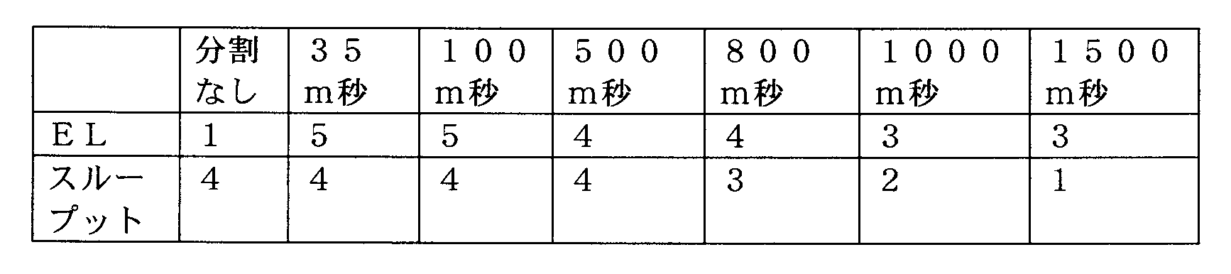
上記表に示した結果から明らかなように、ディレイ時間を長くさせるとEL、スループットが低下していくことが分かる。
したがって、ディレイ時間はできるだけ短くするのがEL向上に好適であることがわかる。
なお、ディレイ時間が長くなるとELが低下していくのは、低露光領域で、得られるパターンと基板との間の密着性不良が発生しているためであるものと推定される。
したがって、ディレイ時間はできるだけ短くするのがEL向上に好適であることがわかる。
なお、ディレイ時間が長くなるとELが低下していくのは、低露光領域で、得られるパターンと基板との間の密着性不良が発生しているためであるものと推定される。
[実施例3]
実施例1-1と同様に、ラジカル重合性モノマー及び光ラジカル重合開始剤を、それぞれ、A-1、B-2として2分割、3分割露光時の各露光(第1露光、第2露光、第3露光)における露光量の変更によるELを評価した。
2分割露光、3分割露光については、各露光間のディレイ時間は35m秒とした。
また、分割なし、2分割露光、3分割露光のいずれについても照射量(露光量)の合計は、100~500mJ/cm2の範囲内で行った。
評価基準は以下の通りである。
1:パターンが発現するがELマージン狭かった。
2:パターンが発現しELマージンが評価基準1よりも5%以上向上した。
3:パターンが発現しELマージンが評価基準2よりも5%以上向上した。
4:パターンが発現しELマージンが評価基準3よりも5%以上向上した。
5:パターンが発現しELマージンが評価基準4よりも5%以上向上した。
6:パターンが発現しELマージンが評価基準5よりも5%以上向上した。
実施例1-1と同様に、ラジカル重合性モノマー及び光ラジカル重合開始剤を、それぞれ、A-1、B-2として2分割、3分割露光時の各露光(第1露光、第2露光、第3露光)における露光量の変更によるELを評価した。
2分割露光、3分割露光については、各露光間のディレイ時間は35m秒とした。
また、分割なし、2分割露光、3分割露光のいずれについても照射量(露光量)の合計は、100~500mJ/cm2の範囲内で行った。
評価基準は以下の通りである。
1:パターンが発現するがELマージン狭かった。
2:パターンが発現しELマージンが評価基準1よりも5%以上向上した。
3:パターンが発現しELマージンが評価基準2よりも5%以上向上した。
4:パターンが発現しELマージンが評価基準3よりも5%以上向上した。
5:パターンが発現しELマージンが評価基準4よりも5%以上向上した。
6:パターンが発現しELマージンが評価基準5よりも5%以上向上した。
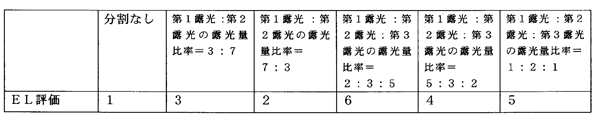
上記表に示した結果から明らかなように、分割露光における露光量の比率は第1露光の露光量が小さく、分割回数が多い方がELが向上することが分かる。
これは、第1露光の露光量が第2露光の露光量より大きい場合、第1露光でのラジカルの拡散が大きく、第2露光の寄与が小さいためと推定される。すなわち、結果的に分割しない露光に近いものとなるためと考えられる。
また、分割回数が多い場合においては、トータルの露光量が同一であっても、第1露光、第2露光等の単位露光の露光量が小さいため、露光による横方向(線幅へ寄与)へのラジカル拡散が酸素阻害により失活するためELが向上するものと考えられる。
しかしながら横方向へのラジカルの失活に比べ、基板方向への失活は遅くなると考えられるので、得られるパターンと基板との間の密着性の劣化は大きくならないと推測される。
これは、第1露光の露光量が第2露光の露光量より大きい場合、第1露光でのラジカルの拡散が大きく、第2露光の寄与が小さいためと推定される。すなわち、結果的に分割しない露光に近いものとなるためと考えられる。
また、分割回数が多い場合においては、トータルの露光量が同一であっても、第1露光、第2露光等の単位露光の露光量が小さいため、露光による横方向(線幅へ寄与)へのラジカル拡散が酸素阻害により失活するためELが向上するものと考えられる。
しかしながら横方向へのラジカルの失活に比べ、基板方向への失活は遅くなると考えられるので、得られるパターンと基板との間の密着性の劣化は大きくならないと推測される。
本発明のカラーフィルタの製造方法は、液晶表示素子や固体撮像素子に適用することが可能であり、特に100万画素を超えるような高解像度のCCD素子やCMOS等に好適である。特に1.0μm以下のピクセルサイズのカラーフィルタの製造時に好適である。
本発明によれば、スループットを損なうことなく、EL及びDOFの尤度を向上させることができ、上記マスク追従性の向上により、カラーフィルタ画素アレイパターンの矩形性も向上することができるカラーフィルタの製造方法、並びにこれを用いて製造されるカラーフィルタ、固体撮像素子、及び液晶表示装置を提供することができる。
特に本発明のカラーフィルタの製造方法によれば、固体撮像素子用カラーフィルタ(赤、緑、青、CMY(シアン、マゼンタ、イエロー)、透明等)における、特に1.2μmを下回るピクセルサイズの画素において、EL(マスク追従性)及びDOFを効果的に向上させることができ、また上面及び断面から観察され得るカラーフィルタパターンの矩形性を向上させることができる。
特に本発明のカラーフィルタの製造方法によれば、固体撮像素子用カラーフィルタ(赤、緑、青、CMY(シアン、マゼンタ、イエロー)、透明等)における、特に1.2μmを下回るピクセルサイズの画素において、EL(マスク追従性)及びDOFを効果的に向上させることができ、また上面及び断面から観察され得るカラーフィルタパターンの矩形性を向上させることができる。
本発明を詳細にまた特定の実施態様を参照して説明したが、本発明の精神と範囲を逸脱することなく様々な変更や修正を加えることができることは当業者にとって明らかである。
本出願は、2013年2月18日出願の日本特許出願(特願2013-029361)に基づくものであり、その内容はここに参照として取り込まれる。
本出願は、2013年2月18日出願の日本特許出願(特願2013-029361)に基づくものであり、その内容はここに参照として取り込まれる。
10 固体撮像素子
13 カラーフィルタ
14 平坦化層
15 マイクロレンズ
20G 緑色画素(第1色画素)
20R 赤色画素(第2色画素)
20B 青色画素(第3色画素)
41 Pウエル
42 受光素子(フォトダイオード)
43 不純物拡散層
44 電極
45 配線層
46 BPSG膜
47 絶縁膜
48 P-SiN膜
49 平坦化層
13 カラーフィルタ
14 平坦化層
15 マイクロレンズ
20G 緑色画素(第1色画素)
20R 赤色画素(第2色画素)
20B 青色画素(第3色画素)
41 Pウエル
42 受光素子(フォトダイオード)
43 不純物拡散層
44 電極
45 配線層
46 BPSG膜
47 絶縁膜
48 P-SiN膜
49 平坦化層
Claims (11)
- ラジカル重合性モノマー及び光ラジカル重合開始剤を含有する感光性着色層をカラーフィルタ画素アレイ用のフォトマスクを用いて露光する工程、及び
前記露光後の感光性着色層を現像することによりカラーフィルタ画素アレイパターンを形成する工程を有し、前記露光が同一座標で連続して複数回に分割して行われる、カラーフィルタの製造方法。 - 前記分割された露光間の露光しない時間が1000m秒以内である、請求項1に記載のカラーフィルタの製造方法。
- 前記複数回に分割された露光が3回以上に分割された露光である、請求項1又は2に記載のカラーフィルタの製造方法。
- 前記複数回に分割された露光について、1回目の露光による露光量が2回目の露光による露光量よりも小さい、請求項1~3のいずれか1項に記載のカラーフィルタの製造方法。
- 前記カラーフィルタ画素アレイパターンがBayerパターンである、請求項1~4のいずれか1項に記載のカラーフィルタの製造方法。
- 前記感光性着色層が、有機化合物である色材を含有する、請求項1~5のいずれか1項に記載のカラーフィルタの製造方法。
- 前記有機化合物である色材が有機顔料である、請求項6に記載のカラーフィルタの製造方法。
- 前記感光性着色層が、無機顔料を含有する、請求項1~5のいずれか1項に記載のカラーフィルタの製造方法。
- 請求項1~8のいずれか1項に記載のカラーフィルタの製造方法により得られるカラーフィルタ。
- 請求項9に記載のカラーフィルタを有する固体撮像素子。
- 請求項9に記載のカラーフィルタを有する液晶表示装置。
Applications Claiming Priority (2)
| Application Number | Priority Date | Filing Date | Title |
|---|---|---|---|
| JP2013-029361 | 2013-02-18 | ||
| JP2013029361A JP6047417B2 (ja) | 2013-02-18 | 2013-02-18 | カラーフィルタの製造方法、固体撮像素子の製造方法、及び液晶表示装置の製造方法 |
Publications (1)
| Publication Number | Publication Date |
|---|---|
| WO2014125935A1 true WO2014125935A1 (ja) | 2014-08-21 |
Family
ID=51353944
Family Applications (1)
| Application Number | Title | Priority Date | Filing Date |
|---|---|---|---|
| PCT/JP2014/052153 Ceased WO2014125935A1 (ja) | 2013-02-18 | 2014-01-30 | カラーフィルタの製造方法、並びにこれを用いて製造されるカラーフィルタ、固体撮像素子、及び液晶表示装置 |
Country Status (3)
| Country | Link |
|---|---|
| JP (1) | JP6047417B2 (ja) |
| TW (1) | TW201439603A (ja) |
| WO (1) | WO2014125935A1 (ja) |
Families Citing this family (2)
| Publication number | Priority date | Publication date | Assignee | Title |
|---|---|---|---|---|
| JPWO2023234094A1 (ja) * | 2022-06-01 | 2023-12-07 | ||
| WO2023234095A1 (ja) * | 2022-06-01 | 2023-12-07 | 富士フイルム株式会社 | 光検出素子、イメージセンサおよび光検出素子の製造方法 |
Citations (3)
| Publication number | Priority date | Publication date | Assignee | Title |
|---|---|---|---|---|
| JP2008287213A (ja) * | 2007-01-12 | 2008-11-27 | Toyo Ink Mfg Co Ltd | 着色組成物およびカラーフィルタの製造方法 |
| JP2009169413A (ja) * | 2007-12-19 | 2009-07-30 | Toppan Printing Co Ltd | カラーフィルタの製造方法およびカラーフィルタ |
| JP2010085600A (ja) * | 2008-09-30 | 2010-04-15 | Fujifilm Corp | 着色硬化性組成物、カラーフィルタ及びその製造方法、並びに固体撮像素子 |
-
2013
- 2013-02-18 JP JP2013029361A patent/JP6047417B2/ja not_active Expired - Fee Related
-
2014
- 2014-01-30 WO PCT/JP2014/052153 patent/WO2014125935A1/ja not_active Ceased
- 2014-02-14 TW TW103104815A patent/TW201439603A/zh unknown
Patent Citations (3)
| Publication number | Priority date | Publication date | Assignee | Title |
|---|---|---|---|---|
| JP2008287213A (ja) * | 2007-01-12 | 2008-11-27 | Toyo Ink Mfg Co Ltd | 着色組成物およびカラーフィルタの製造方法 |
| JP2009169413A (ja) * | 2007-12-19 | 2009-07-30 | Toppan Printing Co Ltd | カラーフィルタの製造方法およびカラーフィルタ |
| JP2010085600A (ja) * | 2008-09-30 | 2010-04-15 | Fujifilm Corp | 着色硬化性組成物、カラーフィルタ及びその製造方法、並びに固体撮像素子 |
Also Published As
| Publication number | Publication date |
|---|---|
| JP2014157340A (ja) | 2014-08-28 |
| JP6047417B2 (ja) | 2016-12-21 |
| TW201439603A (zh) | 2014-10-16 |
Similar Documents
| Publication | Publication Date | Title |
|---|---|---|
| JP7232881B2 (ja) | 着色感光性組成物、硬化膜、パターン形成方法、遮光膜付き赤外光カットフィルタ、固体撮像素子、画像表示装置および赤外線センサ | |
| TWI547760B (zh) | 用於固態攝影元件的彩色濾光片的感光性透明組成物、以及使用其的固態攝影元件的彩色濾光片的製造方法、固態攝影元件的彩色濾光片以及固態攝影元件 | |
| KR101784247B1 (ko) | 중합성 조성물, 경화막, 컬러필터, 컬러필터의 제조 방법, 및 고체 촬상 소자 | |
| JP5743588B2 (ja) | 着色感放射線性組成物、パターンの形成方法、カラーフィルタの製造方法、カラーフィルタ、および固体撮像素子 | |
| JP6411548B2 (ja) | 着色組成物、着色組成物の製造方法、カラーフィルタ、パターン形成方法、カラーフィルタの製造方法、固体撮像素子、および、画像表示装置 | |
| JP7109624B2 (ja) | 組成物、硬化膜、カラーフィルタ、遮光膜、固体撮像装置及び画像表示装置 | |
| JP6591540B2 (ja) | 硬化性組成物、硬化性組成物の製造方法、膜、赤外線カットフィルタ、赤外線透過フィルタ、パターン形成方法および装置 | |
| JP5699064B2 (ja) | カラーフィルタの製造方法 | |
| JP5798978B2 (ja) | 着色感放射線性組成物、これを用いたカラーフィルタ | |
| WO2015029643A1 (ja) | 着色感光性樹脂組成物、硬化膜、カラーフィルタ、カラーフィルタの製造方法、固体撮像素子、および画像表示装置 | |
| JP2015151530A (ja) | 複合体およびその製造方法、着色組成物、硬化膜、カラーフィルタ、カラーフィルタの製造方法、固体撮像素子および画像表示装置、ならびに、積層体よび積層体 | |
| JP6147135B2 (ja) | 着色感光性樹脂組成物、硬化膜、カラーフィルタ、カラーフィルタの製造方法、固体撮像素子、および画像表示装置 | |
| JP6840220B2 (ja) | 樹脂組成物、膜、赤外線カットフィルタ及びその製造方法、固体撮像素子、赤外線センサ、並びに、カメラモジュール | |
| WO2016072259A1 (ja) | 着色硬化性組成物、カラーフィルタ、パターン形成方法、カラーフィルタの製造方法、固体撮像素子、および、画像表示装置 | |
| JP2011141512A (ja) | 黒色硬化性組成物、遮光性カラーフィルタ、固体撮像素子、ウエハレベルレンズ、遮光膜およびその製造方法 | |
| WO2015053183A1 (ja) | 感光性組成物、分散組成物、これを用いたカラーフィルタの製造方法、カラーフィルタ、及び、固体撮像素子 | |
| KR20140027028A (ko) | 착색 감방사선성 조성물, 이것을 사용한 컬러 필터 | |
| WO2010119924A1 (ja) | カラーフィルタ用重合性組成物、カラーフィルタ、及び固体撮像素子 | |
| KR20140137015A (ko) | 경화층 또는 경화패턴의 형성방법, 컬러필터의 제조방법, 및 이들을 사용해서 제조되는 컬러필터, 고체촬상소자 및 액정표시장치 | |
| WO2017213028A1 (ja) | 着色組成物および膜の製造方法 | |
| JP6071816B2 (ja) | 樹脂硬化物の製造方法、これを用いた固体撮像素子および液晶表示装置の製造方法 | |
| JP2013054079A (ja) | 光硬化性組成物、カラーフィルタ及びその製造方法、並びに固体撮像素子 | |
| JP6047417B2 (ja) | カラーフィルタの製造方法、固体撮像素子の製造方法、及び液晶表示装置の製造方法 | |
| JP6764894B2 (ja) | 赤外線透過フィルタ用組成物、赤外線透過フィルタ、赤外線透過フィルタの製造方法、及び、赤外線センサー | |
| JP2013210542A (ja) | カラーフィルタの製造方法、並びにこれを用いて製造されるカラーフィルタ、固体撮像素子、及び液晶表示装置 |
Legal Events
| Date | Code | Title | Description |
|---|---|---|---|
| 121 | Ep: the epo has been informed by wipo that ep was designated in this application |
Ref document number: 14751493 Country of ref document: EP Kind code of ref document: A1 |
|
| NENP | Non-entry into the national phase |
Ref country code: DE |
|
| 122 | Ep: pct application non-entry in european phase |
Ref document number: 14751493 Country of ref document: EP Kind code of ref document: A1 |