WO2014125657A1 - Dispositif électronique - Google Patents
Dispositif électronique Download PDFInfo
- Publication number
- WO2014125657A1 WO2014125657A1 PCT/JP2013/058801 JP2013058801W WO2014125657A1 WO 2014125657 A1 WO2014125657 A1 WO 2014125657A1 JP 2013058801 W JP2013058801 W JP 2013058801W WO 2014125657 A1 WO2014125657 A1 WO 2014125657A1
- Authority
- WO
- WIPO (PCT)
- Prior art keywords
- back cover
- protrusion
- display panel
- flat plate
- wall
- Prior art date
Links
Images


Classifications
-
- H—ELECTRICITY
- H04—ELECTRIC COMMUNICATION TECHNIQUE
- H04N—PICTORIAL COMMUNICATION, e.g. TELEVISION
- H04N5/00—Details of television systems
- H04N5/64—Constructional details of receivers, e.g. cabinets or dust covers
Definitions
- Embodiments described herein relate generally to an electronic device having a display screen.
- the problem to be solved by the present invention is to provide a highly reliable electronic device.
- An electronic apparatus includes a display panel, a flat plate portion, a back cover that covers the back of the display panel, and a pair of first walls that are provided integrally with the back cover and extend away from the display panel. And a second protrusion extending between the pair of first wall portions, a first protrusion extending in a direction intersecting with a longitudinal direction of the back cover at the flat plate portion, A pair of third wall portions that are provided integrally with the back cover adjacent to the first projecting portion and extend in a direction approaching the display panel, and a fourth wall portion between the pair of third wall portions. And a second projecting portion extending in a direction intersecting with the longitudinal direction of the back cover at the flat plate portion.
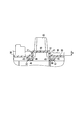
- FIG. 2 is a cross-sectional view of the video display device shown in FIG. 1 taken along line F2-F2.
- the disassembled perspective view which showed the state which removed the unit cover from the back cover of the video display apparatus shown in FIG.
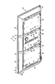
- the rear view which showed the state which removed the unit cover of the video display apparatus shown in FIG.
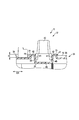
- FIG. 7 is a cross-sectional view taken along line F8-F8 of the back cover of the video display device shown in FIG.
- the rear view which showed from the back the back cover of the video display apparatus which is an example of the electronic device of 2nd Embodiment.
- the perspective view which showed from the back the back cover of the video display apparatus which is an example of the electronic device of 3rd Embodiment.
- the rear view which showed from the back the back cover of the video display apparatus which is an example of the electronic device of 4th Embodiment.
- the video display device (television) of the embodiment is an example of an electronic device and has a substantially rectangular appearance.
- the front side (that is, the user side) is the front direction F
- the back side as viewed from the user is the rear direction B
- the left side when viewed from the user is the left direction L
- the right side when viewed from the user is the right direction R
- the user The upward direction as viewed from the upper side is defined as the upward direction U
- the downward direction as viewed from the user is defined as the downward direction D.
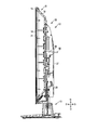
- the video display device 11 includes a main body portion 12 and leg portions 13 (support portions, stands) that support the main body portion 12.
- the leg portion 13 is attached to the back cover 16 described later via a second metal fitting 29 described later, and can support the second metal fitting 29 and the main body portion 12.
- the main body portion 12 includes a flat display panel 14 that forms a display screen, and a front cover 15 that is provided in front of the display panel 14 and covers the front thereof.
- Front bezel, mask a back cover 16 provided behind the display panel 14 to cover the back of the display panel 14, a reflector 17 attached to the front surface of the back cover 16, and a reflection on the front surface of the back cover 16.
- a light source 18 attached to the front side of the plate 17, a plurality of optical sheets 21 fixed to the front surface of the reflecting plate 17 and capable of exhibiting various optical actions, a back cover 16 provided on the front side of the optical sheet 21,
- An intermediate member 22 (middle frame) that sandwiches the reflector 17 and the optical sheet 21 therebetween.
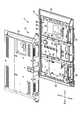
- the video display device 11 further includes a system board 23, a power circuit board 24 and a liquid crystal driving board 25 fixed on the rear surface of the back cover 16, and a pair on the lower side of the back cover 16.
- a speaker 26 provided on the back cover 16, a unit cover 27 (second back cover) that is attached to and covers the back cover 16, and a first metal fitting 28 that is fixed to a first protrusion 31 described later of the back cover 16, respectively.
- a second metal fitting 29 fixed to the back cover 16 so as to straddle the two first protrusions 31 of the back cover 16.
- the system board 23 is fixed at a position on the right side (left side as viewed from the front side) of the first projection part 31 and the second projection part 32 on the right side (left side as viewed from the front direction) described later. Is done.
- the power supply circuit board 24 is fixed to a position on the left side (right side as viewed from the front side) of the first projection part 31 and the second projection part 32 on the left side (right side as viewed from the front direction) described later.
- the liquid crystal drive substrate 25 is fixed at a position between the two first protrusions 31 (second protrusions 32).
- the display panel 14 is composed of a liquid crystal cell formed by bonding two glass substrates.
- the display panel 14 is not limited to a liquid crystal panel, and may be another type of display panel such as a plasma display panel, an organic EL, a plastic display panel, a sheet display panel, or the like.
- the display panel 14 is fixed with respect to the intermediate member 22.
- the front cover 15 is provided in a frame shape (frame shape), for example, of a synthetic resin material, and the display panel 14 is exposed to the outside through an opening provided in the center.
- the front cover 15, the back cover 16, and the unit cover 27 constitute a housing 33 of the video display device 11.
- the light source 18 is composed of an elongated substrate 34 (LED substrate) on which a plurality of LEDs are mounted side by side. As shown in FIG. 1, in the present embodiment, the light source 18 includes five substrates 34 and can directly illuminate the display panel 14 from behind. Therefore, the light source 18 constitutes a so-called direct type backlight.
- LED substrate elongated substrate 34
- the light source 18 includes five substrates 34 and can directly illuminate the display panel 14 from behind. Therefore, the light source 18 constitutes a so-called direct type backlight.
- the reflector 17 has a dish shape along the inner surface of the back cover 16 (see FIG. 5).
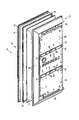
- the back cover 16 is formed into a square dish shape as a whole by a synthetic resin material.
- the back cover 16 includes a flat plate portion 35 having a flat plate shape and a bent portion 36 provided around the flat plate portion 35 (upper side, right side, and left side) so as to rise obliquely from the periphery of the flat plate portion 35.
- the bending portion 36 is provided in the vicinity of the outer peripheral portion of the back cover 16.
- the back cover 16 includes a first protruding portion 31 protruding from the flat plate portion 35 in a direction away from the display panel 14 and a second protruding portion 32 protruding from the flat plate portion 35 in a direction approaching the display panel 14. Have.
- the first projecting portion 31 and the second projecting portion 32 are provided at a substantially central portion in the longitudinal direction D1 of the back cover 16.
- the first protrusion 31 and the second protrusion 32 are formed integrally with the flat plate portion 35.
- the 1st protrusion part 31 and the 2nd protrusion part 32 are extended in the direction D2 (namely, vertical direction) which cross
- the substantially full width of the back cover 16 corresponds to the full width of the flat plate portion 35 of the back cover 16.
- the 1st protrusion part 31 and the 2nd protrusion part 32 are provided only in the flat plate part 35, and are not provided in the bending part 36.
- first protrusions 31 are provided. As shown in FIG. 8, the first protrusion 31 is formed in a substantially “U” cross section and is provided integrally with the back cover 16.
- the first protruding portion 31 includes a pair of first wall portions 41 extending in a direction away from the display panel 14 and a flat plate-like second wall portion 42 extending between the pair of first wall portions 41. is doing.
- the first protruding portion 31 protrudes from the flat plate portion 35 to several mm to several tens mm.
- a boss portion 43 and a pair of concave portions 44 for fixing the first metal fitting 28 are provided in the vicinity of the center portion of the first projecting portion 31.
- the boss portion 43 and the pair of recesses 44 are an example of a fixing portion to which the first metal fitting 28 is fixed.
- the first protrusion 31 is provided wider than the second protrusion 32.
- the system board 23, the power supply circuit board 24, and the liquid crystal drive board 25 are fixed to the back cover 16 at a position away from the first protrusion 31 and the second protrusion 32.
- the system board 23, the power supply circuit board 24, and the liquid crystal driving board 25 are provided within the range of the height H of the first protrusion 31.
- the system board 23, the power supply circuit board 24, and the liquid crystal drive board 25 are on the opposite side (rear face) of the flat plate portion 35 to the surface facing the display panel 14, and the top surface (second wall) of the first protruding portion 31. Provided at a position closer to the display panel 14 than the portion 42).
- the system board 23, the power supply circuit board 24, and the liquid crystal driving board 25 are an example of a printed circuit board provided within the range of the height of the first protrusion 31.
- the second protrusion 32 is adjacent to the first protrusion 31 and is provided continuously with the first protrusion 31. Similar to the first protrusion 31, the second protrusion 32 is provided with a substantially “U” -shaped cross section, and is provided integrally with the back cover 16.
- the second projecting portion 32 includes a pair of third wall portions 45 extending in a direction approaching the display panel 14 and a fourth wall portion 46 extending between the pair of third wall portions 45. .
- the third wall portion 45 is provided continuously with the first wall portion 41 of the first protruding portion 31. More specifically, the third wall portion 45 is provided on substantially the same straight line as the first wall portion 41.
- the second protrusion 32 protrudes from the flat plate part 35 to several mm to several tens of mm.
- the first protrusion 31 is provided at a position between the pair of second protrusions 32.
- a recess 47 is provided on the back side of the second protrusion 32.
- the first metal fitting 28 is formed by bending a metal material (carbon steel, iron) or the like into a predetermined shape.
- the first metal fitting 28 includes a pair of left and right claw portions 51 that fit into the recess 44, an attachment portion 53 that is fixed to the boss portion 43 (back cover 16) with a fixing tool 52 such as a screw, and a pin that is fixed when hanging on the wall. And a plate-like portion 54 through which the member 55 (see FIG. 2) is passed.
- FIG. 7 only the first metal fitting 28 on the right side (left side when viewed from the front) is shown, but the first metal fitting 28 having the same shape is attached to the left concave portion 44 and the boss portion 43. .
- the mounting portion 53 and the plate-like portion 54 are each provided with a circular opening, and the opening is in the opening.
- the fixing member 55 or the fixing tool 52 is passed.
- the second metal fitting 29 is formed by bending a metal material (carbon steel, iron) or the like into a substantially “L” cross section.
- the second metal fitting 29 includes a main body 61 provided with a plurality of reinforcing drawing portions 56 at a plurality of locations, and a first bent portion 62 that is bent in a direction approaching the display panel 14 from one end of the main body 61.
- a second bent portion 63 bent in a direction away from the display panel 14 from the other end portion of the main body portion 61, and an overlapping portion provided continuously with the main body portion 61 and overlapping one end portion of the first protruding portion 31.
- the first bent portion 62 and the second bent portion 63 are provided mainly for the purpose of improving the strength of the second metal fitting 29. Further, the leg portion 13 is fixed to the second metal fitting 29 in a state where the tip end portion abuts against the second bent portion 63 (see FIG. 2).
- the overlapping portion 64 is in close contact with a part of the first protruding portion 31 (an end portion of the first protruding portion 31), and reinforces the first protruding portion 31 at the position.
- the second metal fitting 29 is fixed to the first projecting portion 31 at the position of the overlapping portion 64 by fixing means 67 such as a screw passing through the opening in the overlapping portion 64. For this reason, the second metal fitting 29 is integrally fixed to one end portion (lower end portion) of the first projecting portion 31 of the back cover 16.
- the video display device 11 includes the display panel 14, the flat plate portion 35, the back cover 16 that covers the back of the display panel 14, and the display panel 14 that is provided integrally with the back cover 16.
- a pair of first wall portions 41 extending in a direction away from each other and a second wall portion 42 extending between the pair of first wall portions 41, and a longitudinal direction D1 of the back cover 16 at the flat plate portion 35.
- a first projecting portion 31 extending in the intersecting direction D2, a pair of third wall portions 45 adjacent to the first projecting portion 31 and provided integrally with the back cover 16 and extending in a direction approaching the display panel 14, and a pair A fourth wall portion 46 extending between the third wall portions 45, and a second projecting portion 32 extending in the direction D2 intersecting the longitudinal direction D1 of the back cover 16 at the flat plate portion 35.
- the first protruding portion 31 extending in the direction D2 intersecting the longitudinal direction D1 of the back cover 16 can be provided on the flat plate portion 35. Accordingly, it is possible to provide the video display device 11 having the back cover 16 that is difficult to bend with respect to the load in the front-rear direction. Further, the metal reinforcing frame extending in the direction D2 intersecting the longitudinal direction D1 of the back cover 16, which is necessary in the conventional video display device 11, can be eliminated, and the number of parts can be reduced and assembled. Man-hours and manufacturing costs can be reduced. Further, the weight of the video display device 11 can be reduced.
- the first wall portion 41 is provided continuously with the third wall portion 45. According to this structure, the 1st protrusion part 31 and the 2nd protrusion part 32 can be provided densely in the fixed area in the longitudinal direction D1 of the back cover 16. FIG. Accordingly, the video display device 11 having the back cover 16 that is more difficult to bend with respect to the load in the front-rear direction can be provided.
- the first wall portion 41 is provided on the same straight line as the third wall portion 45. According to this configuration, the section modulus of the back cover 16 can be further efficiently improved while preventing an increase in the thickness dimension of the video display device 11. Accordingly, it is possible to provide the video display device 11 that is more difficult to bend with respect to the load in the front-rear direction.
- the video display device 11 includes a first metal fitting 28 through which a fixing member 55 is passed when hanging on the wall, and the first projecting portion 31 has a fixing part to which the first metal fitting 28 is fixed. According to this configuration, since the fixing portion is provided on the first protruding portion 31 protruding in the direction away from the display panel 14, the height of the first metal fitting 28 can be reduced. In addition, the first projecting portion having high rigidity can be disposed in a portion where a large load is applied in the back cover 16 when used on the wall, and the stability when used on the wall can be improved.
- the video display device 11 includes an overlapping portion 64 that overlaps one end of the first protruding portion 31, and a second metal fitting 29 fixed to the first protruding portion 31 by the overlapping portion 64, and a second metal fitting 29. And a leg 13 that supports the second metal fitting 29.
- the image display device is stronger against a load in the front-rear direction. 11 can be provided.
- the second metal fitting 29 has an insertion portion 66, and the insertion portion 66 is inserted into a recess 47 provided on the back side of the second protrusion 32.
- a bending structure can be formed between the overlapping portion 64 of the second metal fitting 29 and the insertion portion 66, and the length of the insertion portion 66 can be secured long by using the recess 47.
- the rigidity of the 2nd metal fitting 29 can be improved (the section modulus of the 2nd metal fitting 29 can be made high), and the bending load in the front-back direction can also be strengthened also as the image display device 11 whole.
- the image display device 11 is fixed to the back cover 16 at a position away from the first projecting portion 31 and the second projecting portion 32, and a printed circuit board provided within the height range of the first projecting portion 31. Prepare. According to this configuration, it is possible to improve the space use efficiency inside the video display device 11, thereby realizing a reduction in the thickness of the video display device 11.
- the video display device 11 includes a bent portion 36 provided on the back cover 16 around the flat plate portion 35, and the first projecting portion 31 and the second projecting portion 32 are provided at a substantially central portion in the longitudinal direction D1 of the back cover 16. Is provided. According to this configuration, the rigidity can be improved by the first protrusion 31 and the second protrusion 32 in a portion (that is, the central portion) other than the portion whose rigidity is increased by the bending portion 36. Thereby, high rigidity can be efficiently realized in the entire back cover 16.
- the back cover 16 is made of a resin material. According to this configuration, it is possible to reduce the weight and the price of the video display device 11.
- the width of the first protrusion 31 (the dimension of the first protrusion 31 in the longitudinal direction D1 of the back cover 16) is the first protrusion of the first embodiment. It is larger than the part 31.
- the video display device 11 of the second embodiment is different from that of the first embodiment in this point, but the other parts are common to the first embodiment. For this reason, about the height of the 1st wall part 41 of the 1st protrusion part 31, and the structure and magnitude
- the second wall portion 42 of the first projecting portion 31 is formed in a flat plate shape as in the first embodiment, but a wave-shaped cross section (continuous and continuous with the second wall portion 42) ( It can also be a so-called sine curve-shaped cross section.
- the section modulus of the first protrusion 31 can be further improved, and the back cover 16 that is difficult to bend with respect to the load in the front-rear direction and the video display device 11 including the back cover 16 can be realized.
- the video display device 11 that is an example of the electronic device of the third embodiment is configured such that the first protrusion 31 and the second protrusion 32 are not only the flat plate portion 35 of the back cover 16 but also the bent portion. It has reached 36.
- the 1st protrusion part 31 and the 2nd protrusion part 32 are extended in the direction D2 (namely, vertical direction) which cross
- the video display device 11 of the second embodiment is different from that of the first embodiment in the above points, but the other parts are common to the first embodiment.
- the first protrusion 31 and the second protrusion 32 can be provided in substantially the entire width of the back cover 16 in the direction D2 intersecting the longitudinal direction D1 of the back cover 16. Accordingly, it is possible to provide the back cover 16 that is less likely to bend with respect to the load in the front-rear direction and the video display device 11 including the back cover 16.
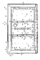
- the video display device that is an example of the electronic device of the fourth embodiment is provided with a total of four first protrusions 31, and two on each side of each first protrusion 31.
- the second protrusions 32 (that is, a total of eight second protrusions 32) are provided.
- the 1st protrusion part 31 is arrange
- the video display device 11 of the second embodiment is different from that of the first embodiment in the above points, but the other parts are common to the first embodiment.
- the number of the first protrusions 31 and the second protrusions 32 can be increased as compared with the first embodiment, and the back cover 16 is less likely to bend with respect to the load in the front-rear direction.
- the video display apparatus 11 provided with the same can be provided. That is, the number of the 1st protrusion parts 31 and the 2nd protrusion parts 32 is not limited to the example of 1st Embodiment, Naturally it may be larger than the example of 1st Embodiment.
- the video display device 11 which is an example of the electronic device of the fourth embodiment, has the second protrusion 32 disposed at the position of the first protrusion 31, and the position of the second protrusion 32.
- the 1st protrusion part 31 is arrange
- the video display device 11 of the second embodiment is different from that of the first embodiment in the above points, but the other parts are common to the first embodiment. For this reason, the following description will mainly focus on differences from the first embodiment, and illustration or description of common parts will be omitted.
- the back cover 16 includes a first protruding portion 31 protruding from the flat plate portion 35 in a direction away from the display panel 14 and a second protruding portion 32 protruding from the flat plate portion 35 in a direction approaching the display panel 14.
- the first projecting portion 31 and the second projecting portion 32 extend in the direction D2 (that is, the longitudinal direction) intersecting the longitudinal direction D1 of the back cover 16, as in FIG. 6 and the like of the first embodiment. It extends over substantially the entire width of the back cover 16 at D2. Further, the first projecting portion 31 and the second projecting portion 32 are formed integrally with the flat plate portion 35.
- first protrusions 31 are provided.
- the first protrusion 31 is formed in a substantially “U” cross section and is provided integrally with the back cover 16.
- the first protruding portion 31 includes a pair of first wall portions 41 extending in a direction away from the display panel 14 and a flat plate-like second wall portion 42 extending between the pair of first wall portions 41. is doing.
- the first protruding portion 31 protrudes from the flat plate portion 35 to several mm to several tens mm.
- a system board 23, a power supply circuit board 24, and a liquid crystal drive board 25 as shown in FIG. 3 are provided within the range of the height H of the first protrusion 31.
- the system board 23, the power supply circuit board 24, and the liquid crystal driving board 25 are an example of a printed circuit board provided within the range of the height of the first protrusion 31.
- the first protrusion 31 is provided narrower than the second protrusion 32.
- two second protrusions 32 are provided. As shown in FIG. 12, the second protrusion 32 is adjacent to the first protrusion 31 and is provided continuously with the first protrusion 31. Similar to the first protrusion 31, the second protrusion 32 is provided with a substantially “U” -shaped cross section, and is provided integrally with the back cover 16.
- the second projecting portion 32 includes a pair of third wall portions 45 extending in a direction approaching the display panel 14 and a fourth wall portion 46 extending between the pair of third wall portions 45. .
- the third wall portion 45 is provided continuously with the first wall portion 41 of the first protruding portion 31. More specifically, the third wall portion 45 is provided on substantially the same straight line as the first wall portion 41.
- the second protruding portion 32 protrudes from several mm to several tens mm from the flat plate portion.
- the second protrusion 32 is provided at a position between the pair of first protrusions 31.
- the back cover 16 that is difficult to bend with respect to the load in the front-rear direction and the back cover 16 are provided.
- the provided video display apparatus 11 can be provided.
- the video display device 11 is not limited to the above-described embodiment as it is, and can be embodied by modifying the constituent elements without departing from the scope of the invention in the implementation stage.
- various inventions can be formed by appropriately combining a plurality of constituent elements disclosed in the embodiment. For example, some components may be deleted from all the components shown in the embodiment. Furthermore, you may combine the component covering different embodiment suitably.
Landscapes
- Engineering & Computer Science (AREA)
- Multimedia (AREA)
- Signal Processing (AREA)
- Devices For Indicating Variable Information By Combining Individual Elements (AREA)
Abstract
Un dispositif électronique selon un mode de réalisation de la présente invention comporte : un panneau d'affichage, un revêtement arrière qui comprend une section de plaque plate (35) et qui recouvre l'arrière du panneau d'affichage ; une paire de premières sections de paroi (41) qui sont pourvues de manière intégrée du revêtement arrière et qui s'étendent dans une direction conduisant à l'opposé du panneau d'affichage ; une seconde section de paroi (42) qui couvre la zone entre la paire de premières sections de paroi ; une première section de saillie (31) qui s'étend dans une direction qui intersecte la direction de longueur du revêtement arrière au niveau de la section de plaque plate ; une paire de troisièmes sections de paroi (45) qui sont adjacentes à la première section de saillie, qui sont pourvues de manière intégrée du revêtement arrière, et qui s'étendent dans une direction qui approche le panneau d'affichage ; une quatrième section de paroi (46) qui couvre la zone entre la paire de troisièmes sections de paroi ; et une seconde section de saillie (32) qui s'étend dans une direction qui intersecte la direction de longueur du revêtement arrière au niveau de la section de plaque plate.
Applications Claiming Priority (2)
| Application Number | Priority Date | Filing Date | Title |
|---|---|---|---|
| JP2013-025736 | 2013-02-13 | ||
| JP2013025736A JP2014153672A (ja) | 2013-02-13 | 2013-02-13 | 電子機器 |
Publications (1)
| Publication Number | Publication Date |
|---|---|
| WO2014125657A1 true WO2014125657A1 (fr) | 2014-08-21 |
Family
ID=51353680
Family Applications (1)
| Application Number | Title | Priority Date | Filing Date |
|---|---|---|---|
| PCT/JP2013/058801 WO2014125657A1 (fr) | 2013-02-13 | 2013-03-26 | Dispositif électronique |
Country Status (2)
| Country | Link |
|---|---|
| JP (1) | JP2014153672A (fr) |
| WO (1) | WO2014125657A1 (fr) |
Cited By (1)
| Publication number | Priority date | Publication date | Assignee | Title |
|---|---|---|---|---|
| EP3264400A4 (fr) * | 2015-02-23 | 2018-03-28 | Panasonic Intellectual Property Management Co., Ltd. | Dispositif d'affichage et plaque arrière utilisée dans ledit dispositif d'affichage |
Citations (10)
| Publication number | Priority date | Publication date | Assignee | Title |
|---|---|---|---|---|
| JPH052164A (ja) * | 1991-01-28 | 1993-01-08 | Toshiba Corp | Lcdモジユール |
| JPH07210093A (ja) * | 1994-01-26 | 1995-08-11 | Fujitsu General Ltd | プラズマディスプレイ装置 |
| JP2001345586A (ja) * | 2000-06-02 | 2001-12-14 | Pioneer Electronic Corp | プラズマディスプレイ装置 |
| JP2005121897A (ja) * | 2003-10-16 | 2005-05-12 | Nec Lcd Technologies Ltd | 液晶表示装置 |
| JP2006337776A (ja) * | 2005-06-02 | 2006-12-14 | Sharp Corp | 薄型表示装置、および液晶表示装置 |
| WO2008142773A1 (fr) * | 2007-05-21 | 2008-11-27 | Hitachi, Ltd. | Module et dispositif d'affichage à plasma |
| JP2009069792A (ja) * | 2007-09-13 | 2009-04-02 | Samsung Sdi Co Ltd | 液晶表示装置 |
| JP2009210882A (ja) * | 2008-03-05 | 2009-09-17 | Canon Inc | 画像表示装置 |
| JP2011085903A (ja) | 2009-09-17 | 2011-04-28 | Panasonic Corp | 画像表示装置 |
| JP2012053082A (ja) * | 2010-08-31 | 2012-03-15 | Hitachi Consumer Electronics Co Ltd | 画像表示装置 |
-
2013
- 2013-02-13 JP JP2013025736A patent/JP2014153672A/ja active Pending
- 2013-03-26 WO PCT/JP2013/058801 patent/WO2014125657A1/fr active Application Filing
Patent Citations (10)
| Publication number | Priority date | Publication date | Assignee | Title |
|---|---|---|---|---|
| JPH052164A (ja) * | 1991-01-28 | 1993-01-08 | Toshiba Corp | Lcdモジユール |
| JPH07210093A (ja) * | 1994-01-26 | 1995-08-11 | Fujitsu General Ltd | プラズマディスプレイ装置 |
| JP2001345586A (ja) * | 2000-06-02 | 2001-12-14 | Pioneer Electronic Corp | プラズマディスプレイ装置 |
| JP2005121897A (ja) * | 2003-10-16 | 2005-05-12 | Nec Lcd Technologies Ltd | 液晶表示装置 |
| JP2006337776A (ja) * | 2005-06-02 | 2006-12-14 | Sharp Corp | 薄型表示装置、および液晶表示装置 |
| WO2008142773A1 (fr) * | 2007-05-21 | 2008-11-27 | Hitachi, Ltd. | Module et dispositif d'affichage à plasma |
| JP2009069792A (ja) * | 2007-09-13 | 2009-04-02 | Samsung Sdi Co Ltd | 液晶表示装置 |
| JP2009210882A (ja) * | 2008-03-05 | 2009-09-17 | Canon Inc | 画像表示装置 |
| JP2011085903A (ja) | 2009-09-17 | 2011-04-28 | Panasonic Corp | 画像表示装置 |
| JP2012053082A (ja) * | 2010-08-31 | 2012-03-15 | Hitachi Consumer Electronics Co Ltd | 画像表示装置 |
Cited By (1)
| Publication number | Priority date | Publication date | Assignee | Title |
|---|---|---|---|---|
| EP3264400A4 (fr) * | 2015-02-23 | 2018-03-28 | Panasonic Intellectual Property Management Co., Ltd. | Dispositif d'affichage et plaque arrière utilisée dans ledit dispositif d'affichage |
Also Published As
| Publication number | Publication date |
|---|---|
| JP2014153672A (ja) | 2014-08-25 |
Similar Documents
| Publication | Publication Date | Title |
|---|---|---|
| JP6195698B2 (ja) | 表示装置 | |
| TWI399589B (zh) | 背光組件及具有該背光組件之顯示裝置 | |
| JP2005196210A5 (fr) | ||
| US10771731B2 (en) | Display device | |
| JP3194934U (ja) | 平面表示装置 | |
| JP5660314B2 (ja) | 表示装置 | |
| JP5519758B2 (ja) | 液晶表示装置 | |
| US9261721B2 (en) | Display apparatus | |
| US9798177B2 (en) | Display apparatus including touch panel fixing a display panel to a backlight unit | |
| JP2012037672A (ja) | 表示装置 | |
| JP5304628B2 (ja) | 液晶モジュール | |
| JP2014021224A (ja) | 電気光学装置および電子機器 | |
| JP2012053119A (ja) | 液晶モジュール | |
| JP2012155235A (ja) | 液晶モジュール | |
| CN109413463A (zh) | 显示模组和电视机 | |
| JP6167522B2 (ja) | 表示装置 | |
| WO2014125657A1 (fr) | Dispositif électronique | |
| CN209803520U (zh) | 直下式液晶显示装置及电视机 | |
| US10823994B2 (en) | Display apparatus | |
| JP6173710B2 (ja) | 電子機器 | |
| JP4636081B2 (ja) | 表示器用照明装置 | |
| JP4659813B2 (ja) | 表示器用照明装置 | |
| KR20110017162A (ko) | 디스플레이 장치 | |
| WO2014103385A1 (fr) | Appareil d'affichage et unité d'affichage | |
| JP5550708B2 (ja) | 電子機器 |
Legal Events
| Date | Code | Title | Description |
|---|---|---|---|
| WWE | Wipo information: entry into national phase |
Ref document number: 2013750254 Country of ref document: EP |
|
| 121 | Ep: the epo has been informed by wipo that ep was designated in this application |
Ref document number: 13750254 Country of ref document: EP Kind code of ref document: A1 |
|
| WD | Withdrawal of designations after international publication | ||
| NENP | Non-entry into the national phase |
Ref country code: DE |