WO2014125657A1 - Electronic device - Google Patents
Electronic device Download PDFInfo
- Publication number
- WO2014125657A1 WO2014125657A1 PCT/JP2013/058801 JP2013058801W WO2014125657A1 WO 2014125657 A1 WO2014125657 A1 WO 2014125657A1 JP 2013058801 W JP2013058801 W JP 2013058801W WO 2014125657 A1 WO2014125657 A1 WO 2014125657A1
- Authority
- WO
- WIPO (PCT)
- Prior art keywords
- back cover
- protrusion
- display panel
- flat plate
- wall
- Prior art date
Links
Images


Classifications
-
- H—ELECTRICITY
- H04—ELECTRIC COMMUNICATION TECHNIQUE
- H04N—PICTORIAL COMMUNICATION, e.g. TELEVISION
- H04N5/00—Details of television systems
- H04N5/64—Constructional details of receivers, e.g. cabinets or dust covers
Definitions
- Embodiments described herein relate generally to an electronic device having a display screen.
- the problem to be solved by the present invention is to provide a highly reliable electronic device.
- An electronic apparatus includes a display panel, a flat plate portion, a back cover that covers the back of the display panel, and a pair of first walls that are provided integrally with the back cover and extend away from the display panel. And a second protrusion extending between the pair of first wall portions, a first protrusion extending in a direction intersecting with a longitudinal direction of the back cover at the flat plate portion, A pair of third wall portions that are provided integrally with the back cover adjacent to the first projecting portion and extend in a direction approaching the display panel, and a fourth wall portion between the pair of third wall portions. And a second projecting portion extending in a direction intersecting with the longitudinal direction of the back cover at the flat plate portion.
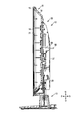
- FIG. 2 is a cross-sectional view of the video display device shown in FIG. 1 taken along line F2-F2.
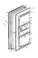
- the disassembled perspective view which showed the state which removed the unit cover from the back cover of the video display apparatus shown in FIG.
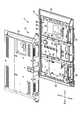
- the rear view which showed the state which removed the unit cover of the video display apparatus shown in FIG.
- FIG. 7 is a cross-sectional view taken along line F8-F8 of the back cover of the video display device shown in FIG.
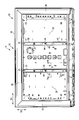
- the rear view which showed from the back the back cover of the video display apparatus which is an example of the electronic device of 2nd Embodiment.
- the perspective view which showed from the back the back cover of the video display apparatus which is an example of the electronic device of 3rd Embodiment.
- the rear view which showed from the back the back cover of the video display apparatus which is an example of the electronic device of 4th Embodiment.
- the video display device (television) of the embodiment is an example of an electronic device and has a substantially rectangular appearance.
- the front side (that is, the user side) is the front direction F
- the back side as viewed from the user is the rear direction B
- the left side when viewed from the user is the left direction L
- the right side when viewed from the user is the right direction R
- the user The upward direction as viewed from the upper side is defined as the upward direction U
- the downward direction as viewed from the user is defined as the downward direction D.
- the video display device 11 includes a main body portion 12 and leg portions 13 (support portions, stands) that support the main body portion 12.
- the leg portion 13 is attached to the back cover 16 described later via a second metal fitting 29 described later, and can support the second metal fitting 29 and the main body portion 12.
- the main body portion 12 includes a flat display panel 14 that forms a display screen, and a front cover 15 that is provided in front of the display panel 14 and covers the front thereof.
- Front bezel, mask a back cover 16 provided behind the display panel 14 to cover the back of the display panel 14, a reflector 17 attached to the front surface of the back cover 16, and a reflection on the front surface of the back cover 16.
- a light source 18 attached to the front side of the plate 17, a plurality of optical sheets 21 fixed to the front surface of the reflecting plate 17 and capable of exhibiting various optical actions, a back cover 16 provided on the front side of the optical sheet 21,
- An intermediate member 22 (middle frame) that sandwiches the reflector 17 and the optical sheet 21 therebetween.
- the video display device 11 further includes a system board 23, a power circuit board 24 and a liquid crystal driving board 25 fixed on the rear surface of the back cover 16, and a pair on the lower side of the back cover 16.
- a speaker 26 provided on the back cover 16, a unit cover 27 (second back cover) that is attached to and covers the back cover 16, and a first metal fitting 28 that is fixed to a first protrusion 31 described later of the back cover 16, respectively.
- a second metal fitting 29 fixed to the back cover 16 so as to straddle the two first protrusions 31 of the back cover 16.
- the system board 23 is fixed at a position on the right side (left side as viewed from the front side) of the first projection part 31 and the second projection part 32 on the right side (left side as viewed from the front direction) described later. Is done.
- the power supply circuit board 24 is fixed to a position on the left side (right side as viewed from the front side) of the first projection part 31 and the second projection part 32 on the left side (right side as viewed from the front direction) described later.
- the liquid crystal drive substrate 25 is fixed at a position between the two first protrusions 31 (second protrusions 32).
- the display panel 14 is composed of a liquid crystal cell formed by bonding two glass substrates.
- the display panel 14 is not limited to a liquid crystal panel, and may be another type of display panel such as a plasma display panel, an organic EL, a plastic display panel, a sheet display panel, or the like.
- the display panel 14 is fixed with respect to the intermediate member 22.
- the front cover 15 is provided in a frame shape (frame shape), for example, of a synthetic resin material, and the display panel 14 is exposed to the outside through an opening provided in the center.
- the front cover 15, the back cover 16, and the unit cover 27 constitute a housing 33 of the video display device 11.
- the light source 18 is composed of an elongated substrate 34 (LED substrate) on which a plurality of LEDs are mounted side by side. As shown in FIG. 1, in the present embodiment, the light source 18 includes five substrates 34 and can directly illuminate the display panel 14 from behind. Therefore, the light source 18 constitutes a so-called direct type backlight.
- LED substrate elongated substrate 34
- the light source 18 includes five substrates 34 and can directly illuminate the display panel 14 from behind. Therefore, the light source 18 constitutes a so-called direct type backlight.
- the reflector 17 has a dish shape along the inner surface of the back cover 16 (see FIG. 5).
- the back cover 16 is formed into a square dish shape as a whole by a synthetic resin material.
- the back cover 16 includes a flat plate portion 35 having a flat plate shape and a bent portion 36 provided around the flat plate portion 35 (upper side, right side, and left side) so as to rise obliquely from the periphery of the flat plate portion 35.
- the bending portion 36 is provided in the vicinity of the outer peripheral portion of the back cover 16.
- the back cover 16 includes a first protruding portion 31 protruding from the flat plate portion 35 in a direction away from the display panel 14 and a second protruding portion 32 protruding from the flat plate portion 35 in a direction approaching the display panel 14. Have.
- the first projecting portion 31 and the second projecting portion 32 are provided at a substantially central portion in the longitudinal direction D1 of the back cover 16.
- the first protrusion 31 and the second protrusion 32 are formed integrally with the flat plate portion 35.
- the 1st protrusion part 31 and the 2nd protrusion part 32 are extended in the direction D2 (namely, vertical direction) which cross
- the substantially full width of the back cover 16 corresponds to the full width of the flat plate portion 35 of the back cover 16.
- the 1st protrusion part 31 and the 2nd protrusion part 32 are provided only in the flat plate part 35, and are not provided in the bending part 36.
- first protrusions 31 are provided. As shown in FIG. 8, the first protrusion 31 is formed in a substantially “U” cross section and is provided integrally with the back cover 16.
- the first protruding portion 31 includes a pair of first wall portions 41 extending in a direction away from the display panel 14 and a flat plate-like second wall portion 42 extending between the pair of first wall portions 41. is doing.
- the first protruding portion 31 protrudes from the flat plate portion 35 to several mm to several tens mm.
- a boss portion 43 and a pair of concave portions 44 for fixing the first metal fitting 28 are provided in the vicinity of the center portion of the first projecting portion 31.
- the boss portion 43 and the pair of recesses 44 are an example of a fixing portion to which the first metal fitting 28 is fixed.
- the first protrusion 31 is provided wider than the second protrusion 32.
- the system board 23, the power supply circuit board 24, and the liquid crystal drive board 25 are fixed to the back cover 16 at a position away from the first protrusion 31 and the second protrusion 32.
- the system board 23, the power supply circuit board 24, and the liquid crystal driving board 25 are provided within the range of the height H of the first protrusion 31.
- the system board 23, the power supply circuit board 24, and the liquid crystal drive board 25 are on the opposite side (rear face) of the flat plate portion 35 to the surface facing the display panel 14, and the top surface (second wall) of the first protruding portion 31. Provided at a position closer to the display panel 14 than the portion 42).
- the system board 23, the power supply circuit board 24, and the liquid crystal driving board 25 are an example of a printed circuit board provided within the range of the height of the first protrusion 31.
- the second protrusion 32 is adjacent to the first protrusion 31 and is provided continuously with the first protrusion 31. Similar to the first protrusion 31, the second protrusion 32 is provided with a substantially “U” -shaped cross section, and is provided integrally with the back cover 16.
- the second projecting portion 32 includes a pair of third wall portions 45 extending in a direction approaching the display panel 14 and a fourth wall portion 46 extending between the pair of third wall portions 45. .
- the third wall portion 45 is provided continuously with the first wall portion 41 of the first protruding portion 31. More specifically, the third wall portion 45 is provided on substantially the same straight line as the first wall portion 41.
- the second protrusion 32 protrudes from the flat plate part 35 to several mm to several tens of mm.
- the first protrusion 31 is provided at a position between the pair of second protrusions 32.
- a recess 47 is provided on the back side of the second protrusion 32.
- the first metal fitting 28 is formed by bending a metal material (carbon steel, iron) or the like into a predetermined shape.
- the first metal fitting 28 includes a pair of left and right claw portions 51 that fit into the recess 44, an attachment portion 53 that is fixed to the boss portion 43 (back cover 16) with a fixing tool 52 such as a screw, and a pin that is fixed when hanging on the wall. And a plate-like portion 54 through which the member 55 (see FIG. 2) is passed.
- FIG. 7 only the first metal fitting 28 on the right side (left side when viewed from the front) is shown, but the first metal fitting 28 having the same shape is attached to the left concave portion 44 and the boss portion 43. .
- the mounting portion 53 and the plate-like portion 54 are each provided with a circular opening, and the opening is in the opening.
- the fixing member 55 or the fixing tool 52 is passed.
- the second metal fitting 29 is formed by bending a metal material (carbon steel, iron) or the like into a substantially “L” cross section.
- the second metal fitting 29 includes a main body 61 provided with a plurality of reinforcing drawing portions 56 at a plurality of locations, and a first bent portion 62 that is bent in a direction approaching the display panel 14 from one end of the main body 61.
- a second bent portion 63 bent in a direction away from the display panel 14 from the other end portion of the main body portion 61, and an overlapping portion provided continuously with the main body portion 61 and overlapping one end portion of the first protruding portion 31.
- the first bent portion 62 and the second bent portion 63 are provided mainly for the purpose of improving the strength of the second metal fitting 29. Further, the leg portion 13 is fixed to the second metal fitting 29 in a state where the tip end portion abuts against the second bent portion 63 (see FIG. 2).
- the overlapping portion 64 is in close contact with a part of the first protruding portion 31 (an end portion of the first protruding portion 31), and reinforces the first protruding portion 31 at the position.
- the second metal fitting 29 is fixed to the first projecting portion 31 at the position of the overlapping portion 64 by fixing means 67 such as a screw passing through the opening in the overlapping portion 64. For this reason, the second metal fitting 29 is integrally fixed to one end portion (lower end portion) of the first projecting portion 31 of the back cover 16.
- the video display device 11 includes the display panel 14, the flat plate portion 35, the back cover 16 that covers the back of the display panel 14, and the display panel 14 that is provided integrally with the back cover 16.
- a pair of first wall portions 41 extending in a direction away from each other and a second wall portion 42 extending between the pair of first wall portions 41, and a longitudinal direction D1 of the back cover 16 at the flat plate portion 35.
- a first projecting portion 31 extending in the intersecting direction D2, a pair of third wall portions 45 adjacent to the first projecting portion 31 and provided integrally with the back cover 16 and extending in a direction approaching the display panel 14, and a pair A fourth wall portion 46 extending between the third wall portions 45, and a second projecting portion 32 extending in the direction D2 intersecting the longitudinal direction D1 of the back cover 16 at the flat plate portion 35.
- the first protruding portion 31 extending in the direction D2 intersecting the longitudinal direction D1 of the back cover 16 can be provided on the flat plate portion 35. Accordingly, it is possible to provide the video display device 11 having the back cover 16 that is difficult to bend with respect to the load in the front-rear direction. Further, the metal reinforcing frame extending in the direction D2 intersecting the longitudinal direction D1 of the back cover 16, which is necessary in the conventional video display device 11, can be eliminated, and the number of parts can be reduced and assembled. Man-hours and manufacturing costs can be reduced. Further, the weight of the video display device 11 can be reduced.
- the first wall portion 41 is provided continuously with the third wall portion 45. According to this structure, the 1st protrusion part 31 and the 2nd protrusion part 32 can be provided densely in the fixed area in the longitudinal direction D1 of the back cover 16. FIG. Accordingly, the video display device 11 having the back cover 16 that is more difficult to bend with respect to the load in the front-rear direction can be provided.
- the first wall portion 41 is provided on the same straight line as the third wall portion 45. According to this configuration, the section modulus of the back cover 16 can be further efficiently improved while preventing an increase in the thickness dimension of the video display device 11. Accordingly, it is possible to provide the video display device 11 that is more difficult to bend with respect to the load in the front-rear direction.
- the video display device 11 includes a first metal fitting 28 through which a fixing member 55 is passed when hanging on the wall, and the first projecting portion 31 has a fixing part to which the first metal fitting 28 is fixed. According to this configuration, since the fixing portion is provided on the first protruding portion 31 protruding in the direction away from the display panel 14, the height of the first metal fitting 28 can be reduced. In addition, the first projecting portion having high rigidity can be disposed in a portion where a large load is applied in the back cover 16 when used on the wall, and the stability when used on the wall can be improved.
- the video display device 11 includes an overlapping portion 64 that overlaps one end of the first protruding portion 31, and a second metal fitting 29 fixed to the first protruding portion 31 by the overlapping portion 64, and a second metal fitting 29. And a leg 13 that supports the second metal fitting 29.
- the image display device is stronger against a load in the front-rear direction. 11 can be provided.
- the second metal fitting 29 has an insertion portion 66, and the insertion portion 66 is inserted into a recess 47 provided on the back side of the second protrusion 32.
- a bending structure can be formed between the overlapping portion 64 of the second metal fitting 29 and the insertion portion 66, and the length of the insertion portion 66 can be secured long by using the recess 47.
- the rigidity of the 2nd metal fitting 29 can be improved (the section modulus of the 2nd metal fitting 29 can be made high), and the bending load in the front-back direction can also be strengthened also as the image display device 11 whole.
- the image display device 11 is fixed to the back cover 16 at a position away from the first projecting portion 31 and the second projecting portion 32, and a printed circuit board provided within the height range of the first projecting portion 31. Prepare. According to this configuration, it is possible to improve the space use efficiency inside the video display device 11, thereby realizing a reduction in the thickness of the video display device 11.
- the video display device 11 includes a bent portion 36 provided on the back cover 16 around the flat plate portion 35, and the first projecting portion 31 and the second projecting portion 32 are provided at a substantially central portion in the longitudinal direction D1 of the back cover 16. Is provided. According to this configuration, the rigidity can be improved by the first protrusion 31 and the second protrusion 32 in a portion (that is, the central portion) other than the portion whose rigidity is increased by the bending portion 36. Thereby, high rigidity can be efficiently realized in the entire back cover 16.
- the back cover 16 is made of a resin material. According to this configuration, it is possible to reduce the weight and the price of the video display device 11.
- the width of the first protrusion 31 (the dimension of the first protrusion 31 in the longitudinal direction D1 of the back cover 16) is the first protrusion of the first embodiment. It is larger than the part 31.
- the video display device 11 of the second embodiment is different from that of the first embodiment in this point, but the other parts are common to the first embodiment. For this reason, about the height of the 1st wall part 41 of the 1st protrusion part 31, and the structure and magnitude
- the second wall portion 42 of the first projecting portion 31 is formed in a flat plate shape as in the first embodiment, but a wave-shaped cross section (continuous and continuous with the second wall portion 42) ( It can also be a so-called sine curve-shaped cross section.
- the section modulus of the first protrusion 31 can be further improved, and the back cover 16 that is difficult to bend with respect to the load in the front-rear direction and the video display device 11 including the back cover 16 can be realized.
- the video display device 11 that is an example of the electronic device of the third embodiment is configured such that the first protrusion 31 and the second protrusion 32 are not only the flat plate portion 35 of the back cover 16 but also the bent portion. It has reached 36.
- the 1st protrusion part 31 and the 2nd protrusion part 32 are extended in the direction D2 (namely, vertical direction) which cross
- the video display device 11 of the second embodiment is different from that of the first embodiment in the above points, but the other parts are common to the first embodiment.
- the first protrusion 31 and the second protrusion 32 can be provided in substantially the entire width of the back cover 16 in the direction D2 intersecting the longitudinal direction D1 of the back cover 16. Accordingly, it is possible to provide the back cover 16 that is less likely to bend with respect to the load in the front-rear direction and the video display device 11 including the back cover 16.
- the video display device that is an example of the electronic device of the fourth embodiment is provided with a total of four first protrusions 31, and two on each side of each first protrusion 31.
- the second protrusions 32 (that is, a total of eight second protrusions 32) are provided.
- the 1st protrusion part 31 is arrange
- the video display device 11 of the second embodiment is different from that of the first embodiment in the above points, but the other parts are common to the first embodiment.
- the number of the first protrusions 31 and the second protrusions 32 can be increased as compared with the first embodiment, and the back cover 16 is less likely to bend with respect to the load in the front-rear direction.
- the video display apparatus 11 provided with the same can be provided. That is, the number of the 1st protrusion parts 31 and the 2nd protrusion parts 32 is not limited to the example of 1st Embodiment, Naturally it may be larger than the example of 1st Embodiment.
- the video display device 11 which is an example of the electronic device of the fourth embodiment, has the second protrusion 32 disposed at the position of the first protrusion 31, and the position of the second protrusion 32.
- the 1st protrusion part 31 is arrange
- the video display device 11 of the second embodiment is different from that of the first embodiment in the above points, but the other parts are common to the first embodiment. For this reason, the following description will mainly focus on differences from the first embodiment, and illustration or description of common parts will be omitted.
- the back cover 16 includes a first protruding portion 31 protruding from the flat plate portion 35 in a direction away from the display panel 14 and a second protruding portion 32 protruding from the flat plate portion 35 in a direction approaching the display panel 14.
- the first projecting portion 31 and the second projecting portion 32 extend in the direction D2 (that is, the longitudinal direction) intersecting the longitudinal direction D1 of the back cover 16, as in FIG. 6 and the like of the first embodiment. It extends over substantially the entire width of the back cover 16 at D2. Further, the first projecting portion 31 and the second projecting portion 32 are formed integrally with the flat plate portion 35.
- first protrusions 31 are provided.
- the first protrusion 31 is formed in a substantially “U” cross section and is provided integrally with the back cover 16.
- the first protruding portion 31 includes a pair of first wall portions 41 extending in a direction away from the display panel 14 and a flat plate-like second wall portion 42 extending between the pair of first wall portions 41. is doing.
- the first protruding portion 31 protrudes from the flat plate portion 35 to several mm to several tens mm.
- a system board 23, a power supply circuit board 24, and a liquid crystal drive board 25 as shown in FIG. 3 are provided within the range of the height H of the first protrusion 31.
- the system board 23, the power supply circuit board 24, and the liquid crystal driving board 25 are an example of a printed circuit board provided within the range of the height of the first protrusion 31.
- the first protrusion 31 is provided narrower than the second protrusion 32.
- two second protrusions 32 are provided. As shown in FIG. 12, the second protrusion 32 is adjacent to the first protrusion 31 and is provided continuously with the first protrusion 31. Similar to the first protrusion 31, the second protrusion 32 is provided with a substantially “U” -shaped cross section, and is provided integrally with the back cover 16.
- the second projecting portion 32 includes a pair of third wall portions 45 extending in a direction approaching the display panel 14 and a fourth wall portion 46 extending between the pair of third wall portions 45. .
- the third wall portion 45 is provided continuously with the first wall portion 41 of the first protruding portion 31. More specifically, the third wall portion 45 is provided on substantially the same straight line as the first wall portion 41.
- the second protruding portion 32 protrudes from several mm to several tens mm from the flat plate portion.
- the second protrusion 32 is provided at a position between the pair of first protrusions 31.
- the back cover 16 that is difficult to bend with respect to the load in the front-rear direction and the back cover 16 are provided.
- the provided video display apparatus 11 can be provided.
- the video display device 11 is not limited to the above-described embodiment as it is, and can be embodied by modifying the constituent elements without departing from the scope of the invention in the implementation stage.
- various inventions can be formed by appropriately combining a plurality of constituent elements disclosed in the embodiment. For example, some components may be deleted from all the components shown in the embodiment. Furthermore, you may combine the component covering different embodiment suitably.
Abstract
An electronic device according to an embodiment of the present invention is provided with: a display panel; a back cover that comprises a flat plate section (35) and that covers the rear of the display panel; a pair of first wall sections (41) that are integrally provided with the back cover and that extend in a direction leading away from the display panel; a second wall section (42) that spans the area between the pair of first wall sections; a first protruding section (31) that extends in a direction that intersects the lengthwise direction of the back cover at the flat plate section; a pair of third wall sections (45) that are adjacent to the first protruding section, that are integrally provided with the back cover, and that extend in a direction that approaches the display panel; a fourth wall section (46) that spans the area between the pair of third wall sections; and a second protruding section (32) that extends in a direction that intersects the lengthwise direction of the back cover at the flat plate section.
Description
本発明の実施形態は、表示画面を有する電子機器に関する。
Embodiments described herein relate generally to an electronic device having a display screen.
電子機器の市場においては、衝撃に強く信頼性が高いモデルが好まれる傾向がある。一方、製品の価格が市場競争力を左右する重要な要素となってきており、製造コストと品質のバランスが重要になってきている。
In the electronic equipment market, there is a tendency to prefer models that are resistant to impact and have high reliability. On the other hand, the price of products has become an important factor affecting market competitiveness, and the balance between manufacturing cost and quality has become important.
本発明が解決しようとする課題は、高信頼性の電子機器を提供することである。
The problem to be solved by the present invention is to provide a highly reliable electronic device.
実施形態の電子機器は、表示パネルと、平板部を有するとともに、前記表示パネルの後方を覆うバックカバーと、前記バックカバーと一体に設けられ前記表示パネルから遠ざかる方向に延びた一対の第1壁部と、前記一対の第1壁部同士の間に亘った第2壁部と、を有するとともに、前記平板部で前記バックカバーの長手方向と交差する方向に延びた第1突出部と、前記第1突出部と隣接して前記バックカバーと一体に設けられ前記表示パネルに近づく方向に延びた一対の第3壁部と、前記一対の第3壁部同士の間に亘った第4壁部と、を有するとともに、前記平板部で前記バックカバーの長手方向と交差する方向に延びた第2突出部と、を備える。
An electronic apparatus according to an embodiment includes a display panel, a flat plate portion, a back cover that covers the back of the display panel, and a pair of first walls that are provided integrally with the back cover and extend away from the display panel. And a second protrusion extending between the pair of first wall portions, a first protrusion extending in a direction intersecting with a longitudinal direction of the back cover at the flat plate portion, A pair of third wall portions that are provided integrally with the back cover adjacent to the first projecting portion and extend in a direction approaching the display panel, and a fourth wall portion between the pair of third wall portions. And a second projecting portion extending in a direction intersecting with the longitudinal direction of the back cover at the flat plate portion.
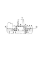
以下、図1から図8を参照して、映像表示装置の第1実施形態について説明する。図1に示すように、実施形態の映像表示装置(テレビジョン)は、電子機器の一例であり、略長方形の外観を有している。以下の実施形態では、手前側(即ちユーザ側)を前方向F、ユーザから見て奥側を後方向B、ユーザから見て左側を左方向L、ユーザから見て右側を右方向R、ユーザから見て上方を上方向U、ユーザから見て下方を下方向Dと定義する。
Hereinafter, a first embodiment of the video display device will be described with reference to FIGS. As shown in FIG. 1, the video display device (television) of the embodiment is an example of an electronic device and has a substantially rectangular appearance. In the following embodiments, the front side (that is, the user side) is the front direction F, the back side as viewed from the user is the rear direction B, the left side when viewed from the user is the left direction L, the right side when viewed from the user is the right direction R, and the user The upward direction as viewed from the upper side is defined as the upward direction U, and the downward direction as viewed from the user is defined as the downward direction D.
図1、図2に示すように、映像表示装置11は、本体部分12と、本体部分12を支持する脚部13(支持部、スタンド)と、を有している。脚部13は、後述する第2金具29を介して後述するバックカバー16に取付けられており、第2金具29および本体部分12を支持することができる。
As shown in FIGS. 1 and 2, the video display device 11 includes a main body portion 12 and leg portions 13 (support portions, stands) that support the main body portion 12. The leg portion 13 is attached to the back cover 16 described later via a second metal fitting 29 described later, and can support the second metal fitting 29 and the main body portion 12.
図1、図2、図5に示すように、本体部分12は、表示画面をなしている平板状の表示パネル14と、表示パネル14の前方に設けられてその前方を覆ったフロントカバー15(フロントベゼル、マスク)と、表示パネル14の後方に設けられて表示パネル14の後方を覆ったバックカバー16と、バックカバー16の前面に取付けられた反射板17と、バックカバー16の前面で反射板17よりも前側に取付けられた光源18と、反射板17の前面に固定され種々の光学作用を発揮できる複数の光学シート21と、光学シート21よりも前側に設けられて、バックカバー16との間に反射板17および光学シート21を挟み込む中間部材22(ミドルフレーム)と、を備えている。
As shown in FIGS. 1, 2, and 5, the main body portion 12 includes a flat display panel 14 that forms a display screen, and a front cover 15 that is provided in front of the display panel 14 and covers the front thereof. Front bezel, mask), a back cover 16 provided behind the display panel 14 to cover the back of the display panel 14, a reflector 17 attached to the front surface of the back cover 16, and a reflection on the front surface of the back cover 16. A light source 18 attached to the front side of the plate 17, a plurality of optical sheets 21 fixed to the front surface of the reflecting plate 17 and capable of exhibiting various optical actions, a back cover 16 provided on the front side of the optical sheet 21, An intermediate member 22 (middle frame) that sandwiches the reflector 17 and the optical sheet 21 therebetween.
図3、図4に示すように、映像表示装置11は、さらに、バックカバー16の後面に固定されたシステム基板23、電源回路基板24および液晶駆動基板25と、バックカバー16の下側に一対に設けられたスピーカ26と、バックカバー16に取付けられてこれらを覆うユニットカバー27(第2バックカバー)と、バックカバー16の後述する第1突出部31にそれぞれ固定される第1金具28と、バックカバー16の2つの第1突出部31にまたがるようにバックカバー16に固定される第2金具29と、を備えている。
As shown in FIGS. 3 and 4, the video display device 11 further includes a system board 23, a power circuit board 24 and a liquid crystal driving board 25 fixed on the rear surface of the back cover 16, and a pair on the lower side of the back cover 16. A speaker 26 provided on the back cover 16, a unit cover 27 (second back cover) that is attached to and covers the back cover 16, and a first metal fitting 28 that is fixed to a first protrusion 31 described later of the back cover 16, respectively. And a second metal fitting 29 fixed to the back cover 16 so as to straddle the two first protrusions 31 of the back cover 16.
図3に示すように、後述する右側(前方向から見て左側)の第1突出部31および第2突出部32よりも右側(前方向から見て左側)の位置に、システム基板23が固定される。同様に後述する左側(前方向から見て右側)の第1突出部31および第2突出部32よりも左側(前方向から見て右側)の位置に、電源回路基板24が固定される。2個の第1突出部31(第2突出部32)の間の位置に、液晶駆動基板25が固定される。
As shown in FIG. 3, the system board 23 is fixed at a position on the right side (left side as viewed from the front side) of the first projection part 31 and the second projection part 32 on the right side (left side as viewed from the front direction) described later. Is done. Similarly, the power supply circuit board 24 is fixed to a position on the left side (right side as viewed from the front side) of the first projection part 31 and the second projection part 32 on the left side (right side as viewed from the front direction) described later. The liquid crystal drive substrate 25 is fixed at a position between the two first protrusions 31 (second protrusions 32).
表示パネル14は、2枚のガラス基板を張り合わせて形成した液晶セルで構成されている。なお、表示パネル14は、液晶パネルに限定されるものではなく、例えばプラズマディスプレイパネル、有機EL、プラスチックディスプレイパネル、シートディスプレイパネル等、他の種類のディスプレイパネルであってもよい。表示パネル14は、中間部材22に対して固定されている。
The display panel 14 is composed of a liquid crystal cell formed by bonding two glass substrates. The display panel 14 is not limited to a liquid crystal panel, and may be another type of display panel such as a plasma display panel, an organic EL, a plastic display panel, a sheet display panel, or the like. The display panel 14 is fixed with respect to the intermediate member 22.
図1に示すように、フロントカバー15は、例えば合成樹脂材料によって、枠状(額縁状)に設けられており、中央部に設けられた開口によって表示パネル14を外部に露出させている。フロントカバー15、バックカバー16、およびユニットカバー27によって、映像表示装置11の筐体33が構成されている。
As shown in FIG. 1, the front cover 15 is provided in a frame shape (frame shape), for example, of a synthetic resin material, and the display panel 14 is exposed to the outside through an opening provided in the center. The front cover 15, the back cover 16, and the unit cover 27 constitute a housing 33 of the video display device 11.
光源18は、複数のLEDを並べて実装した細長い基板34(LED基板)で構成されている。図1に示すように、本実施形態では、光源18は、5個の基板34で構成されており、表示パネル14を後方から直接的に照らすことができる。このため、光源18は、いわゆるダイレクト方式のバックライトを構成する。
The light source 18 is composed of an elongated substrate 34 (LED substrate) on which a plurality of LEDs are mounted side by side. As shown in FIG. 1, in the present embodiment, the light source 18 includes five substrates 34 and can directly illuminate the display panel 14 from behind. Therefore, the light source 18 constitutes a so-called direct type backlight.
反射板17は、バックカバー16の内面に沿った皿型の形状をなしている(図5参照)。
The reflector 17 has a dish shape along the inner surface of the back cover 16 (see FIG. 5).
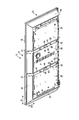
図5、図6等に示すように、バックカバー16は、合成樹脂材料によって、全体として方形の皿型に成形されている。バックカバー16は、平板状をなした平板部35と、平板部35の周囲(上側、右側、左側)に設けられ平板部35の周縁から斜めに立ち上がるように設けられた曲げ部36と、を有している。曲げ部36は、バックカバー16の外周部の近傍に設けられるとも言い換えることができる。
As shown in FIG. 5, FIG. 6, etc., the back cover 16 is formed into a square dish shape as a whole by a synthetic resin material. The back cover 16 includes a flat plate portion 35 having a flat plate shape and a bent portion 36 provided around the flat plate portion 35 (upper side, right side, and left side) so as to rise obliquely from the periphery of the flat plate portion 35. Have. In other words, the bending portion 36 is provided in the vicinity of the outer peripheral portion of the back cover 16.
バックカバー16は、表示パネル14から遠ざかる方向に向けて平板部35から突出した第1突出部31と、表示パネル14に近づく方向に向けて平板部35から突出した第2突出部32と、を有している。第1突出部31および第2突出部32は、バックカバー16の長手方向D1における略中央部に設けられている。
The back cover 16 includes a first protruding portion 31 protruding from the flat plate portion 35 in a direction away from the display panel 14 and a second protruding portion 32 protruding from the flat plate portion 35 in a direction approaching the display panel 14. Have. The first projecting portion 31 and the second projecting portion 32 are provided at a substantially central portion in the longitudinal direction D1 of the back cover 16.
第1突出部31および第2突出部32は、平板部35と一体的に成形されている。第1突出部31および第2突出部32は、バックカバー16の長手方向D1と交差する方向D2(すなわち、縦方向)に延びており、例えば、当該方向D2におけるバックカバー16の実質的な全幅に亘っている。なお、本実施形態において、バックカバー16の実質的な全幅とは、バックカバー16の平板部35の全幅に対応している。このため、本実施形態では、第1突出部31および第2突出部32は、平板部35にだけ設けられており、曲げ部36には設けられない。しかしながら、後述する実施形態のように、第1突出部31および第2突出部32を曲げ部36にまで至るように連続して設けても良い。
The first protrusion 31 and the second protrusion 32 are formed integrally with the flat plate portion 35. The 1st protrusion part 31 and the 2nd protrusion part 32 are extended in the direction D2 (namely, vertical direction) which cross | intersects the longitudinal direction D1 of the back cover 16, for example, substantially full width of the back cover 16 in the said direction D2 It is over. In the present embodiment, the substantially full width of the back cover 16 corresponds to the full width of the flat plate portion 35 of the back cover 16. For this reason, in this embodiment, the 1st protrusion part 31 and the 2nd protrusion part 32 are provided only in the flat plate part 35, and are not provided in the bending part 36. FIG. However, you may provide the 1st protrusion part 31 and the 2nd protrusion part 32 continuously so that the bending part 36 may be reached like embodiment mentioned later.
本実施形態では、第1突出部31は、2個設けられている。図8に示すように、第1突出部31は、断面略「U」字形に形成されており、バックカバー16と一体に設けられている。第1突出部31は、表示パネル14から遠ざかる方向に延びた一対の第1壁部41と、一対の第1壁部41同士の間に亘った平板状の第2壁部42と、を有している。第1突出部31は、平板部35から数mmから数10mm突出している。
In the present embodiment, two first protrusions 31 are provided. As shown in FIG. 8, the first protrusion 31 is formed in a substantially “U” cross section and is provided integrally with the back cover 16. The first protruding portion 31 includes a pair of first wall portions 41 extending in a direction away from the display panel 14 and a flat plate-like second wall portion 42 extending between the pair of first wall portions 41. is doing. The first protruding portion 31 protrudes from the flat plate portion 35 to several mm to several tens mm.
図6、図7に示すように、第1突出部31の中央部付近には、第1金具28を固定するためのボス部43および一対の凹部44が設けられている。ボス部43および一対の凹部44は、第1金具28が固定される固定部の一例である。第1突出部31は、第2突出部32よりも幅広に設けられている。
As shown in FIGS. 6 and 7, a boss portion 43 and a pair of concave portions 44 for fixing the first metal fitting 28 are provided in the vicinity of the center portion of the first projecting portion 31. The boss portion 43 and the pair of recesses 44 are an example of a fixing portion to which the first metal fitting 28 is fixed. The first protrusion 31 is provided wider than the second protrusion 32.
図3に示すように、システム基板23、電源回路基板24および液晶駆動基板25は、第1突出部31および第2突出部32を外れた位置でバックカバー16に固定されている。図8において、第1突出部31の高さHの範囲内に、システム基板23、電源回路基板24および液晶駆動基板25が設けられている。言い換えると、システム基板23、電源回路基板24および液晶駆動基板25は、平板部35の表示パネル14と対向する面とは反対側(後面)で、第1突出部31の頂面(第2壁部42)よりも表示パネル14に近い位置に設けられている。システム基板23、電源回路基板24および液晶駆動基板25は、第1突出部31の高さの範囲内に設けられたプリント回路板の一例である。
As shown in FIG. 3, the system board 23, the power supply circuit board 24, and the liquid crystal drive board 25 are fixed to the back cover 16 at a position away from the first protrusion 31 and the second protrusion 32. In FIG. 8, the system board 23, the power supply circuit board 24, and the liquid crystal driving board 25 are provided within the range of the height H of the first protrusion 31. In other words, the system board 23, the power supply circuit board 24, and the liquid crystal drive board 25 are on the opposite side (rear face) of the flat plate portion 35 to the surface facing the display panel 14, and the top surface (second wall) of the first protruding portion 31. Provided at a position closer to the display panel 14 than the portion 42). The system board 23, the power supply circuit board 24, and the liquid crystal driving board 25 are an example of a printed circuit board provided within the range of the height of the first protrusion 31.
第2突出部32は、本実施形態では、4個設けられている(図3参照)。図8に示すように、第2突出部32は、第1突出部31と隣接しており、第1突出部31と連続的に設けられている。第2突出部32は、第1突出部31と同様に、断面略「U」字形に設けられており、バックカバー16と一体に設けられている。第2突出部32は、表示パネル14に近づく方向に延びた一対の第3壁部45と、一対の第3壁部45同士の間に亘った第4壁部46と、を有している。第3壁部45は、第1突出部31の第1壁部41と連続的に設けられている。さらに具体的には、第3壁部45は、第1壁部41と略同一直線上に設けられている。
In the present embodiment, four second protrusions 32 are provided (see FIG. 3). As shown in FIG. 8, the second protrusion 32 is adjacent to the first protrusion 31 and is provided continuously with the first protrusion 31. Similar to the first protrusion 31, the second protrusion 32 is provided with a substantially “U” -shaped cross section, and is provided integrally with the back cover 16. The second projecting portion 32 includes a pair of third wall portions 45 extending in a direction approaching the display panel 14 and a fourth wall portion 46 extending between the pair of third wall portions 45. . The third wall portion 45 is provided continuously with the first wall portion 41 of the first protruding portion 31. More specifically, the third wall portion 45 is provided on substantially the same straight line as the first wall portion 41.
第2突出部32は、平板部35から数mmから数10mm突出している。第1突出部31は、一対の第2突出部32の間の位置に設けられている。第2突出部32の裏面側には、窪み部47が設けられている。
The second protrusion 32 protrudes from the flat plate part 35 to several mm to several tens of mm. The first protrusion 31 is provided at a position between the pair of second protrusions 32. A recess 47 is provided on the back side of the second protrusion 32.
図4、図7に示すように、第1金具28は、金属材料(炭素鋼、鉄)等を所定の形状に折り曲げて形成されている。第1金具28は、凹部44に嵌る左右一対の爪部51と、ボス部43(バックカバー16)に対してねじ等の固定具52で固定される取付部53と、壁掛け時にピン等の固定部材55(図2参照)が通される板状部54と、を有している。なお、図7では、右側の第1金具28(前方向から見て左側)だけが示されているが、左側の凹部44およびボス部43に対しても同じ形状の第1金具28が取り付けられる。
4 and 7, the first metal fitting 28 is formed by bending a metal material (carbon steel, iron) or the like into a predetermined shape. The first metal fitting 28 includes a pair of left and right claw portions 51 that fit into the recess 44, an attachment portion 53 that is fixed to the boss portion 43 (back cover 16) with a fixing tool 52 such as a screw, and a pin that is fixed when hanging on the wall. And a plate-like portion 54 through which the member 55 (see FIG. 2) is passed. In FIG. 7, only the first metal fitting 28 on the right side (left side when viewed from the front) is shown, but the first metal fitting 28 having the same shape is attached to the left concave portion 44 and the boss portion 43. .
取付部53および板状部54には、それぞれ円形の開口部が設けられており、当該開口部に。固定部材55或いは固定具52が通されている。
The mounting portion 53 and the plate-like portion 54 are each provided with a circular opening, and the opening is in the opening. The fixing member 55 or the fixing tool 52 is passed.
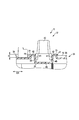
第2金具29は、金属材料(炭素鋼、鉄)等を断面略「L」字形に折り曲げて形成されている。第2金具29は、補強用の絞り加工部56が複数個所に設けられた本体部61と、本体部61の一方の端部から表示パネル14に近づく方向に折り曲げられた第1折り曲げ部62と、本体部61の他方の端部から表示パネル14から遠ざかる方向に折り曲げられた第2折り曲げ部63と、本体部61と連続的に設けられ第1突出部31の一方の端部に重なる重複部64と、本体部61から突出するとともに脚部13を保持した一対の凸部65(凸片)と、重複部64から突出するとともに第2突出部32の裏面側の窪み部に挿入される挿入部66と、を有している。
The second metal fitting 29 is formed by bending a metal material (carbon steel, iron) or the like into a substantially “L” cross section. The second metal fitting 29 includes a main body 61 provided with a plurality of reinforcing drawing portions 56 at a plurality of locations, and a first bent portion 62 that is bent in a direction approaching the display panel 14 from one end of the main body 61. A second bent portion 63 bent in a direction away from the display panel 14 from the other end portion of the main body portion 61, and an overlapping portion provided continuously with the main body portion 61 and overlapping one end portion of the first protruding portion 31. 64, a pair of convex portions 65 (convex pieces) that protrude from the main body portion 61 and hold the leg portion 13, and an insertion that protrudes from the overlapping portion 64 and is inserted into the recess portion on the back surface side of the second protrusion portion 32 Part 66.
第1折り曲げ部62および第2折り曲げ部63は、主として第2金具29の強度を向上する目的で設けられている。また、脚部13は、その先端部を第2折り曲げ部63に突き当てた状態で第2金具29に固定される(図2参照)。重複部64は、第1突出部31の一部(第1突出部31の端部)に密着しており、当該位置で第1突出部31を補強している。第2金具29は、重複部64にある開口を貫通するねじ等の固定手段67によって、重複部64の位置で第1突出部31に固定されている。このため、第2金具29は、バックカバー16の第1突出部31の一方の端部(下側の端部)に一体的に固定されている。
The first bent portion 62 and the second bent portion 63 are provided mainly for the purpose of improving the strength of the second metal fitting 29. Further, the leg portion 13 is fixed to the second metal fitting 29 in a state where the tip end portion abuts against the second bent portion 63 (see FIG. 2). The overlapping portion 64 is in close contact with a part of the first protruding portion 31 (an end portion of the first protruding portion 31), and reinforces the first protruding portion 31 at the position. The second metal fitting 29 is fixed to the first projecting portion 31 at the position of the overlapping portion 64 by fixing means 67 such as a screw passing through the opening in the overlapping portion 64. For this reason, the second metal fitting 29 is integrally fixed to one end portion (lower end portion) of the first projecting portion 31 of the back cover 16.
第1実施形態によれば、映像表示装置11は、表示パネル14と、平板部35を有するとともに、表示パネル14の後方を覆うバックカバー16と、バックカバー16と一体に設けられ表示パネル14から遠ざかる方向に延びた一対の第1壁部41と、一対の第1壁部41同士の間に亘った第2壁部42と、を有するとともに、平板部35でバックカバー16の長手方向D1と交差する方向D2に延びた第1突出部31と、第1突出部31と隣接してバックカバー16と一体に設けられ表示パネル14に近づく方向に延びた一対の第3壁部45と、一対の第3壁部45同士の間に亘った第4壁部46と、を有するとともに、平板部35でバックカバー16の長手方向D1と交差する方向D2に延びた第2突出部32と、を備える。
According to the first embodiment, the video display device 11 includes the display panel 14, the flat plate portion 35, the back cover 16 that covers the back of the display panel 14, and the display panel 14 that is provided integrally with the back cover 16. A pair of first wall portions 41 extending in a direction away from each other and a second wall portion 42 extending between the pair of first wall portions 41, and a longitudinal direction D1 of the back cover 16 at the flat plate portion 35. A first projecting portion 31 extending in the intersecting direction D2, a pair of third wall portions 45 adjacent to the first projecting portion 31 and provided integrally with the back cover 16 and extending in a direction approaching the display panel 14, and a pair A fourth wall portion 46 extending between the third wall portions 45, and a second projecting portion 32 extending in the direction D2 intersecting the longitudinal direction D1 of the back cover 16 at the flat plate portion 35. Prepare.
この構成によれば、平板部35にバックカバー16の長手方向D1と交差する方向D2に延びる第1突出部31を設けることができる。これによって、前後方向への荷重に対して曲がりにくいバックカバー16を有した映像表示装置11を提供することができる。また、従来型の映像表示装置11で必要となっていた、バックカバー16の長手方向D1と交差する方向D2に延びる金属製の補強フレームを不要とすることができ、部品点数を削減して組立工数および製造コストを削減できる。また、映像表示装置11の軽量化を図ることもできる。
According to this configuration, the first protruding portion 31 extending in the direction D2 intersecting the longitudinal direction D1 of the back cover 16 can be provided on the flat plate portion 35. Accordingly, it is possible to provide the video display device 11 having the back cover 16 that is difficult to bend with respect to the load in the front-rear direction. Further, the metal reinforcing frame extending in the direction D2 intersecting the longitudinal direction D1 of the back cover 16, which is necessary in the conventional video display device 11, can be eliminated, and the number of parts can be reduced and assembled. Man-hours and manufacturing costs can be reduced. Further, the weight of the video display device 11 can be reduced.
また、第1壁部41は、第3壁部45と連続的に設けられる。この構成によれば、バックカバー16の長手方向D1における一定区間において、第1突出部31および第2突出部32を密集的に設けることができる。これによって、前後方向への荷重に対してより一層曲がりにくいバックカバー16を有した映像表示装置11を提供できる。
Further, the first wall portion 41 is provided continuously with the third wall portion 45. According to this structure, the 1st protrusion part 31 and the 2nd protrusion part 32 can be provided densely in the fixed area in the longitudinal direction D1 of the back cover 16. FIG. Accordingly, the video display device 11 having the back cover 16 that is more difficult to bend with respect to the load in the front-rear direction can be provided.
第1壁部41は、第3壁部45と同一直線上に設けられている。この構成によれば、映像表示装置11の厚み寸法の増加を防ぎつつ、バックカバー16の断面係数をさらに効率的に向上させることができる。これによって、前後方向への荷重に対してさらに曲がりにくい映像表示装置11を提供できる。
The first wall portion 41 is provided on the same straight line as the third wall portion 45. According to this configuration, the section modulus of the back cover 16 can be further efficiently improved while preventing an increase in the thickness dimension of the video display device 11. Accordingly, it is possible to provide the video display device 11 that is more difficult to bend with respect to the load in the front-rear direction.
映像表示装置11は、壁掛け時に固定部材55が通される第1金具28を備え、第1突出部31は、第1金具28が固定される固定部を有している。この構成によれば、表示パネル14から遠ざかる方向に突出した第1突出部31上に固定部を設けているため、第1金具28の高さを小さく構成することができる。また、壁掛け使用時にバックカバー16中で大きな荷重がかかる部分に、高い剛性を有した第1突出部を配置することができ、壁掛け使用時の安定性を向上できる。
The video display device 11 includes a first metal fitting 28 through which a fixing member 55 is passed when hanging on the wall, and the first projecting portion 31 has a fixing part to which the first metal fitting 28 is fixed. According to this configuration, since the fixing portion is provided on the first protruding portion 31 protruding in the direction away from the display panel 14, the height of the first metal fitting 28 can be reduced. In addition, the first projecting portion having high rigidity can be disposed in a portion where a large load is applied in the back cover 16 when used on the wall, and the stability when used on the wall can be improved.
映像表示装置11は、第1突出部31の一方の端部に重なった重複部64を有し、当該重複部64で第1突出部31に固定された第2金具29と、第2金具29に固定されて第2金具29を支持した脚部13と、を備える。
The video display device 11 includes an overlapping portion 64 that overlaps one end of the first protruding portion 31, and a second metal fitting 29 fixed to the first protruding portion 31 by the overlapping portion 64, and a second metal fitting 29. And a leg 13 that supports the second metal fitting 29.
この構成によれば、第1突出部31と固定された第2金具29によって、さらに第1突出部31の一方の端部を補強できるため、前後方向への荷重に対してより強い映像表示装置11を提供できる。
According to this configuration, since one end of the first protrusion 31 can be further reinforced by the second metal fitting 29 fixed to the first protrusion 31, the image display device is stronger against a load in the front-rear direction. 11 can be provided.
第2金具29は、挿入部66を有し、当該挿入部66は、第2突出部32の裏側に設けられた窪み部47内に挿入されている。この構成によれば、第2金具29の重複部64と挿入部66との間で、曲げ構造を構成できるとともに、窪み部47を利用することで挿入部66の長さを長く確保できる。このため、第2金具29の剛性を向上(第2金具29の断面係数を高く)することができ、映像表示装置11全体としても前後方向における曲げ荷重に強くすることができる。
The second metal fitting 29 has an insertion portion 66, and the insertion portion 66 is inserted into a recess 47 provided on the back side of the second protrusion 32. According to this configuration, a bending structure can be formed between the overlapping portion 64 of the second metal fitting 29 and the insertion portion 66, and the length of the insertion portion 66 can be secured long by using the recess 47. For this reason, the rigidity of the 2nd metal fitting 29 can be improved (the section modulus of the 2nd metal fitting 29 can be made high), and the bending load in the front-back direction can also be strengthened also as the image display device 11 whole.
映像表示装置11は、第1突出部31および第2突出部32を外れた位置でバックカバー16に固定されるとともに、第1突出部31の高さの範囲内に設けられたプリント回路板を備える。この構成によれば、映像表示装置11の内部で、スペースの使用効率を向上することができ、それによって映像表示装置11の薄型化を実現できる。
The image display device 11 is fixed to the back cover 16 at a position away from the first projecting portion 31 and the second projecting portion 32, and a printed circuit board provided within the height range of the first projecting portion 31. Prepare. According to this configuration, it is possible to improve the space use efficiency inside the video display device 11, thereby realizing a reduction in the thickness of the video display device 11.
映像表示装置11は、平板部35の周囲でバックカバー16に設けられた曲げ部36を備え、第1突出部31および第2突出部32は、バックカバー16の長手方向D1における略中央部に設けられている。この構成によれば、曲げ部36によって剛性が高められた部分以外の部分(つまり、中央部)において、第1突出部31および第2突出部32によって剛性を向上できる。これによって、バックカバー16全体において高剛性を効率的に実現することができる。
The video display device 11 includes a bent portion 36 provided on the back cover 16 around the flat plate portion 35, and the first projecting portion 31 and the second projecting portion 32 are provided at a substantially central portion in the longitudinal direction D1 of the back cover 16. Is provided. According to this configuration, the rigidity can be improved by the first protrusion 31 and the second protrusion 32 in a portion (that is, the central portion) other than the portion whose rigidity is increased by the bending portion 36. Thereby, high rigidity can be efficiently realized in the entire back cover 16.
バックカバー16は、樹脂材料で形成される。この構成によれば、映像表示装置11の軽量化および低価格化を実現できる。
The back cover 16 is made of a resin material. According to this configuration, it is possible to reduce the weight and the price of the video display device 11.
続いて、図9を参照して、電子機器の第2実施形態について説明する。第2実施形態の電子機器の一例である映像表示装置11は、第1突出部31の幅(バックカバー16の長手方向D1における第1突出部31の寸法)が第1実施形態の第1突出部31に比して大きくなっている。
Subsequently, a second embodiment of the electronic device will be described with reference to FIG. In the video display device 11 which is an example of the electronic device of the second embodiment, the width of the first protrusion 31 (the dimension of the first protrusion 31 in the longitudinal direction D1 of the back cover 16) is the first protrusion of the first embodiment. It is larger than the part 31.
第2実施形態の映像表示装置11は、この点で第1の実施形態のものと異なっているが、それ以外の部分は第1実施形態と共通している。このため、第1突出部31の第1壁部41の高さや、第2突出部32の構造、大きさについては第1実施形態と同様である。
The video display device 11 of the second embodiment is different from that of the first embodiment in this point, but the other parts are common to the first embodiment. For this reason, about the height of the 1st wall part 41 of the 1st protrusion part 31, and the structure and magnitude | size of the 2nd protrusion part 32, it is the same as that of 1st Embodiment.
第2実施形態によれば、第1突出部31の幅が大きくなった場合でも、前後方向への荷重に対して強いバックカバー16を実現することができ、映像表示装置11の信頼性を向上できる。なお、本実施形態では、第1突出部31の第2壁部42は、第1実施形態と同様に平板状に形成されているが、第2壁部42を繰り返し連続する波型の断面(いわゆるサインカーブ状の断面)にすることもできる。これによって、第1突出部31においてさらに断面係数を向上することができ、前後方向の荷重に対して曲がりにくいバックカバー16およびそれを備えた映像表示装置11を実現できる。
According to the second embodiment, even when the width of the first protrusion 31 is increased, the back cover 16 that is strong against the load in the front-rear direction can be realized, and the reliability of the video display device 11 is improved. it can. In the present embodiment, the second wall portion 42 of the first projecting portion 31 is formed in a flat plate shape as in the first embodiment, but a wave-shaped cross section (continuous and continuous with the second wall portion 42) ( It can also be a so-called sine curve-shaped cross section. As a result, the section modulus of the first protrusion 31 can be further improved, and the back cover 16 that is difficult to bend with respect to the load in the front-rear direction and the video display device 11 including the back cover 16 can be realized.
続いて、図10を参照して、電子機器の第3実施形態について説明する。第3実施形態の電子機器の一例である映像表示装置11は、第1実施形態とは異なり、第1突出部31および第2突出部32がバックカバー16の平板部35だけでなく、曲げ部36にまで至っている。このため、本実施形態においても、第1突出部31および第2突出部32は、バックカバー16の長手方向D1と交差する方向D2(すなわち、縦方向)に延びており、当該方向D2におけるバックカバー16の実質的な全幅に亘っている。
Subsequently, a third embodiment of the electronic device will be described with reference to FIG. Unlike the first embodiment, the video display device 11 that is an example of the electronic device of the third embodiment is configured such that the first protrusion 31 and the second protrusion 32 are not only the flat plate portion 35 of the back cover 16 but also the bent portion. It has reached 36. For this reason, also in this embodiment, the 1st protrusion part 31 and the 2nd protrusion part 32 are extended in the direction D2 (namely, vertical direction) which cross | intersects the longitudinal direction D1 of the back cover 16, and the back in the said direction D2 It covers substantially the entire width of the cover 16.
第2実施形態の映像表示装置11は、上記の点で第1の実施形態のものと異なっているが、それ以外の部分は第1実施形態と共通する。
The video display device 11 of the second embodiment is different from that of the first embodiment in the above points, but the other parts are common to the first embodiment.
第3実施形態によれば、バックカバー16の長手方向D1と交差する方向D2におけるバックカバー16の実質的な全幅において、第1突出部31および第2突出部32を設けることができる。これによって、さらに前後方向の荷重に対して曲がりにくいバックカバー16およびそれを備えた映像表示装置11を提供することができる。
According to the third embodiment, the first protrusion 31 and the second protrusion 32 can be provided in substantially the entire width of the back cover 16 in the direction D2 intersecting the longitudinal direction D1 of the back cover 16. Accordingly, it is possible to provide the back cover 16 that is less likely to bend with respect to the load in the front-rear direction and the video display device 11 including the back cover 16.
続いて、図11を参照して、電子機器の第4実施形態について説明する。第4実施形態の電子機器の一例である映像表示装置は、第1実施形態とは異なり、第1突出部31が計4個設けられており、各第1突出部31の両側に2個の第2突出部32(つまり、合計8個の第2突出部32)が設けられている。第1突出部31は、例えば、いわゆる均等なピッチで配置されている。
Subsequently, a fourth embodiment of the electronic device will be described with reference to FIG. Unlike the first embodiment, the video display device that is an example of the electronic device of the fourth embodiment is provided with a total of four first protrusions 31, and two on each side of each first protrusion 31. The second protrusions 32 (that is, a total of eight second protrusions 32) are provided. The 1st protrusion part 31 is arrange | positioned at what is called a uniform pitch, for example.
第2実施形態の映像表示装置11は、上記の点で第1の実施形態のものと異なっているが、それ以外の部分は第1実施形態と共通する。
The video display device 11 of the second embodiment is different from that of the first embodiment in the above points, but the other parts are common to the first embodiment.
第4実施形態によれば、第1実施形態に比して、第1突出部31および第2突出部32の数を多くすることができ、さらに前後方向の荷重に対して曲がりにくいバックカバー16およびそれを備えた映像表示装置11を提供することができる。すなわち、第1突出部31および第2突出部32の数は、第1実施形態の例に限定されるものではなく、第1実施形態の例よりも多くても当然によい。
According to the fourth embodiment, the number of the first protrusions 31 and the second protrusions 32 can be increased as compared with the first embodiment, and the back cover 16 is less likely to bend with respect to the load in the front-rear direction. And the video display apparatus 11 provided with the same can be provided. That is, the number of the 1st protrusion parts 31 and the 2nd protrusion parts 32 is not limited to the example of 1st Embodiment, Naturally it may be larger than the example of 1st Embodiment.
続いて、図12を参照して、電子機器の第5実施形態について説明する。第4実施形態の電子機器の一例である映像表示装置11は、第1実施形態とは異なり、第1突出部31の位置に第2突出部32が配置され、第2突出部32の位置に第1突出部31が配置される。すなわち、第1突出部31同士の間の位置に第2突出部32が設けられている。第2実施形態の映像表示装置11は、上記の点で第1の実施形態のものと異なっているが、それ以外の部分は第1実施形態と共通する。このため、以下は主として第1実施形態と異なる部分について説明し、共通する部分については図示或いは説明を省略する。
Subsequently, a fifth embodiment of the electronic device will be described with reference to FIG. Unlike the first embodiment, the video display device 11, which is an example of the electronic device of the fourth embodiment, has the second protrusion 32 disposed at the position of the first protrusion 31, and the position of the second protrusion 32. The 1st protrusion part 31 is arrange | positioned. That is, the second protrusion 32 is provided at a position between the first protrusions 31. The video display device 11 of the second embodiment is different from that of the first embodiment in the above points, but the other parts are common to the first embodiment. For this reason, the following description will mainly focus on differences from the first embodiment, and illustration or description of common parts will be omitted.
バックカバー16は、表示パネル14から遠ざかる方向に向けて平板部35から突出した第1突出部31と、表示パネル14に近づく方向に向けて平板部35から突出した第2突出部32と、を有している。第1突出部31および第2突出部32は、第1実施形態の図6等と同様に、バックカバー16の長手方向D1と交差する方向D2(すなわち、縦方向)に延びており、当該方向D2におけるバックカバー16の実質的な全幅に亘っている。また、第1突出部31および第2突出部32は、平板部35と一体的に成形されている。
The back cover 16 includes a first protruding portion 31 protruding from the flat plate portion 35 in a direction away from the display panel 14 and a second protruding portion 32 protruding from the flat plate portion 35 in a direction approaching the display panel 14. Have. The first projecting portion 31 and the second projecting portion 32 extend in the direction D2 (that is, the longitudinal direction) intersecting the longitudinal direction D1 of the back cover 16, as in FIG. 6 and the like of the first embodiment. It extends over substantially the entire width of the back cover 16 at D2. Further, the first projecting portion 31 and the second projecting portion 32 are formed integrally with the flat plate portion 35.
本実施形態では、第1突出部31は、4個設けられている。図12に示すように、第1突出部31は、断面略「U」字形に形成されており、バックカバー16と一体に設けられている。第1突出部31は、表示パネル14から遠ざかる方向に延びた一対の第1壁部41と、一対の第1壁部41同士の間に亘った平板状の第2壁部42と、を有している。第1突出部31は、平板部35から数mmから数10mm突出している。図12において、第1突出部31の高さHの範囲内に、図3に示すようなシステム基板23、電源回路基板24および液晶駆動基板25が設けられている。システム基板23、電源回路基板24および液晶駆動基板25は、第1突出部31の高さの範囲内に設けられたプリント回路板の一例である。
In the present embodiment, four first protrusions 31 are provided. As shown in FIG. 12, the first protrusion 31 is formed in a substantially “U” cross section and is provided integrally with the back cover 16. The first protruding portion 31 includes a pair of first wall portions 41 extending in a direction away from the display panel 14 and a flat plate-like second wall portion 42 extending between the pair of first wall portions 41. is doing. The first protruding portion 31 protrudes from the flat plate portion 35 to several mm to several tens mm. In FIG. 12, a system board 23, a power supply circuit board 24, and a liquid crystal drive board 25 as shown in FIG. 3 are provided within the range of the height H of the first protrusion 31. The system board 23, the power supply circuit board 24, and the liquid crystal driving board 25 are an example of a printed circuit board provided within the range of the height of the first protrusion 31.
本実施形態では、第1突出部31は、第2突出部32よりも幅狭に設けられている。
In the present embodiment, the first protrusion 31 is provided narrower than the second protrusion 32.
第2突出部32は、本実施形態では、2個設けられている。図12に示すように、第2突出部32は、第1突出部31と隣接しており、第1突出部31と連続的に設けられている。第2突出部32は、第1突出部31と同様に、断面略「U」字形に設けられており、バックカバー16と一体に設けられている。第2突出部32は、表示パネル14に近づく方向に延びた一対の第3壁部45と、一対の第3壁部45同士の間に亘った第4壁部46と、を有している。第3壁部45は、第1突出部31の第1壁部41と連続的に設けられている。さらに具体的には、第3壁部45は、第1壁部41と略同一直線上に設けられている。
In the present embodiment, two second protrusions 32 are provided. As shown in FIG. 12, the second protrusion 32 is adjacent to the first protrusion 31 and is provided continuously with the first protrusion 31. Similar to the first protrusion 31, the second protrusion 32 is provided with a substantially “U” -shaped cross section, and is provided integrally with the back cover 16. The second projecting portion 32 includes a pair of third wall portions 45 extending in a direction approaching the display panel 14 and a fourth wall portion 46 extending between the pair of third wall portions 45. . The third wall portion 45 is provided continuously with the first wall portion 41 of the first protruding portion 31. More specifically, the third wall portion 45 is provided on substantially the same straight line as the first wall portion 41.
第2突出部32は、平板部から数mmから数10mm突出している。第2突出部32は、一対の第1突出部31の間の位置に設けられている。
The second protruding portion 32 protrudes from several mm to several tens mm from the flat plate portion. The second protrusion 32 is provided at a position between the pair of first protrusions 31.
第5実施形態によれば、第1実施形態に対して、第1突出部31および第2突出部32の位置を入れ替えたとしても、前後方向の荷重に対して曲がりにくいバックカバー16およびそれを備えた映像表示装置11を提供することができる。
According to the fifth embodiment, even if the positions of the first protrusion 31 and the second protrusion 32 are changed with respect to the first embodiment, the back cover 16 that is difficult to bend with respect to the load in the front-rear direction and the back cover 16 are provided. The provided video display apparatus 11 can be provided.
なお、映像表示装置11(電子機器)は、上記実施形態そのままに限定されるものではなく、実施段階ではその要旨を逸脱しない範囲で構成要素を変形して具体化できる。さらに、上記実施形態に開示されている複数の構成要素の適宜な組み合わせにより種々の発明を形成できる。例えば、実施形態に示される全構成要素から幾つかの構成要素を削除してもよい。更に、異なる実施形態に亘る構成要素を適宜組み合わせてもよい。
Note that the video display device 11 (electronic device) is not limited to the above-described embodiment as it is, and can be embodied by modifying the constituent elements without departing from the scope of the invention in the implementation stage. Furthermore, various inventions can be formed by appropriately combining a plurality of constituent elements disclosed in the embodiment. For example, some components may be deleted from all the components shown in the embodiment. Furthermore, you may combine the component covering different embodiment suitably.
Claims (10)
- 表示パネルと、
平板部を有するとともに、前記表示パネルの後方を覆うバックカバーと、
前記バックカバーと一体に設けられ前記表示パネルから遠ざかる方向に延びた一対の第1壁部と、前記一対の第1壁部同士の間に亘った第2壁部と、を有するとともに、前記平板部で前記バックカバーの長手方向と交差する方向に延びた第1突出部と、
前記第1突出部と隣接して前記バックカバーと一体に設けられ前記表示パネルに近づく方向に延びた一対の第3壁部と、前記一対の第3壁部同士の間に亘った第4壁部と、を有するとともに、前記平板部で前記バックカバーの長手方向と交差する方向に延びた第2突出部と、
を備える電子機器。 A display panel;
A back cover that has a flat plate portion and covers the back of the display panel;
The flat plate includes a pair of first wall portions provided integrally with the back cover and extending in a direction away from the display panel, and a second wall portion extending between the pair of first wall portions. A first protrusion extending in a direction intersecting with the longitudinal direction of the back cover at the portion;
A fourth wall extending between the pair of third wall portions and a pair of third wall portions which are provided integrally with the back cover and extend in a direction approaching the display panel adjacent to the first projecting portion. And a second projecting portion extending in a direction intersecting the longitudinal direction of the back cover at the flat plate portion,
Electronic equipment comprising. - 前記第1壁部は、前記第3壁部と連続的に設けられた請求項1に記載の電子機器。 The electronic device according to claim 1, wherein the first wall portion is provided continuously with the third wall portion.
- 前記第1壁部は、前記第3壁部と略同一直線上に設けられた請求項2に記載の電子機器。 3. The electronic apparatus according to claim 2, wherein the first wall portion is provided on substantially the same straight line as the third wall portion.
- 壁掛け時に固定部材が通される第1金具を備え、
前記第1突出部は、前記第1金具が固定される固定部を有した請求項3に記載の電子機器。 A first bracket through which a fixing member is passed when hanging on a wall;
The electronic device according to claim 3, wherein the first protrusion has a fixing portion to which the first metal fitting is fixed. - 前記第1突出部の一方の端部に重なった重複部を有し、当該重複部で前記第1突出部に固定された第2金具と、
前記第2金具に固定されて前記第2金具を支持した脚部と、
を備える請求項4に記載の電子機器。 A second fitting that has an overlapping portion that overlaps one end of the first protruding portion, and is fixed to the first protruding portion at the overlapping portion;
A leg fixed to the second bracket and supporting the second bracket;
An electronic device according to claim 4. - 前記第2金具は、挿入部を有し、当該挿入部は、前記第2突出部の裏側に設けられた窪み部内に挿入された請求項5に記載の電子機器。 The electronic apparatus according to claim 5, wherein the second metal fitting has an insertion portion, and the insertion portion is inserted into a recess portion provided on the back side of the second protrusion.
- 前記第1突出部および前記第2突出部を外れた位置で前記バックカバーに固定されるとともに、前記第1突出部の高さの範囲内に設けられたプリント回路板を備える請求項6に記載の電子機器。 The printed circuit board according to claim 6, further comprising a printed circuit board that is fixed to the back cover at a position outside the first projecting portion and the second projecting portion, and provided within a height range of the first projecting portion. Electronic equipment.
- 前記平板部の周囲で前記バックカバーに設けられた曲げ部を備え、
前記第1突出部および前記第2突出部は、前記バックカバーの長手方向における略中央部に設けられた請求項7に記載の電子機器。 A bent portion provided on the back cover around the flat plate portion;
The electronic device according to claim 7, wherein the first protrusion and the second protrusion are provided at a substantially central portion in a longitudinal direction of the back cover. - 前記バックカバーは、樹脂材料で形成される請求項8に記載の電子機器。 The electronic device according to claim 8, wherein the back cover is formed of a resin material.
- 表示パネルと、
平板部を有するとともに、前記表示パネルの後方を覆うバックカバーと、
前記平板部で前記バックカバーの長手方向と交差する方向に延びるように設けられ、前記表示パネルから遠ざかる方向に突出した第1突出部と、
前記第1突出部と隣接して設けられ、前記平板部で前記バックカバーの長手方向と交差する方向に延びるとともに、前記表示パネルに近づく方向に突出した第2突出部と、
を備える電子機器。 A display panel;
A back cover that has a flat plate portion and covers the back of the display panel;
A first projecting portion provided in the flat plate portion so as to extend in a direction intersecting with a longitudinal direction of the back cover, and projecting in a direction away from the display panel;
A second projecting portion provided adjacent to the first projecting portion, extending in a direction intersecting a longitudinal direction of the back cover at the flat plate portion, and projecting in a direction approaching the display panel;
Electronic equipment comprising.
Applications Claiming Priority (2)
| Application Number | Priority Date | Filing Date | Title |
|---|---|---|---|
| JP2013-025736 | 2013-02-13 | ||
| JP2013025736A JP2014153672A (en) | 2013-02-13 | 2013-02-13 | Electronic apparatus |
Publications (1)
| Publication Number | Publication Date |
|---|---|
| WO2014125657A1 true WO2014125657A1 (en) | 2014-08-21 |
Family
ID=51353680
Family Applications (1)
| Application Number | Title | Priority Date | Filing Date |
|---|---|---|---|
| PCT/JP2013/058801 WO2014125657A1 (en) | 2013-02-13 | 2013-03-26 | Electronic device |
Country Status (2)
| Country | Link |
|---|---|
| JP (1) | JP2014153672A (en) |
| WO (1) | WO2014125657A1 (en) |
Cited By (1)
| Publication number | Priority date | Publication date | Assignee | Title |
|---|---|---|---|---|
| EP3264400A4 (en) * | 2015-02-23 | 2018-03-28 | Panasonic Intellectual Property Management Co., Ltd. | Display device, and back plate used in display device |
Citations (10)
| Publication number | Priority date | Publication date | Assignee | Title |
|---|---|---|---|---|
| JPH052164A (en) * | 1991-01-28 | 1993-01-08 | Toshiba Corp | Lcd module |
| JPH07210093A (en) * | 1994-01-26 | 1995-08-11 | Fujitsu General Ltd | Plasma display device |
| JP2001345586A (en) * | 2000-06-02 | 2001-12-14 | Pioneer Electronic Corp | Plasma display device |
| JP2005121897A (en) * | 2003-10-16 | 2005-05-12 | Nec Lcd Technologies Ltd | Liquid crystal display |
| JP2006337776A (en) * | 2005-06-02 | 2006-12-14 | Sharp Corp | Thin display device and liquid crystal display device |
| WO2008142773A1 (en) * | 2007-05-21 | 2008-11-27 | Hitachi, Ltd. | Plasma display module and plasma display device |
| JP2009069792A (en) * | 2007-09-13 | 2009-04-02 | Samsung Sdi Co Ltd | Liquid crystal display device |
| JP2009210882A (en) * | 2008-03-05 | 2009-09-17 | Canon Inc | Image display device |
| JP2011085903A (en) | 2009-09-17 | 2011-04-28 | Panasonic Corp | Image display device |
| JP2012053082A (en) * | 2010-08-31 | 2012-03-15 | Hitachi Consumer Electronics Co Ltd | Image display device |
-
2013
- 2013-02-13 JP JP2013025736A patent/JP2014153672A/en active Pending
- 2013-03-26 WO PCT/JP2013/058801 patent/WO2014125657A1/en active Application Filing
Patent Citations (10)
| Publication number | Priority date | Publication date | Assignee | Title |
|---|---|---|---|---|
| JPH052164A (en) * | 1991-01-28 | 1993-01-08 | Toshiba Corp | Lcd module |
| JPH07210093A (en) * | 1994-01-26 | 1995-08-11 | Fujitsu General Ltd | Plasma display device |
| JP2001345586A (en) * | 2000-06-02 | 2001-12-14 | Pioneer Electronic Corp | Plasma display device |
| JP2005121897A (en) * | 2003-10-16 | 2005-05-12 | Nec Lcd Technologies Ltd | Liquid crystal display |
| JP2006337776A (en) * | 2005-06-02 | 2006-12-14 | Sharp Corp | Thin display device and liquid crystal display device |
| WO2008142773A1 (en) * | 2007-05-21 | 2008-11-27 | Hitachi, Ltd. | Plasma display module and plasma display device |
| JP2009069792A (en) * | 2007-09-13 | 2009-04-02 | Samsung Sdi Co Ltd | Liquid crystal display device |
| JP2009210882A (en) * | 2008-03-05 | 2009-09-17 | Canon Inc | Image display device |
| JP2011085903A (en) | 2009-09-17 | 2011-04-28 | Panasonic Corp | Image display device |
| JP2012053082A (en) * | 2010-08-31 | 2012-03-15 | Hitachi Consumer Electronics Co Ltd | Image display device |
Cited By (1)
| Publication number | Priority date | Publication date | Assignee | Title |
|---|---|---|---|---|
| EP3264400A4 (en) * | 2015-02-23 | 2018-03-28 | Panasonic Intellectual Property Management Co., Ltd. | Display device, and back plate used in display device |
Also Published As
| Publication number | Publication date |
|---|---|
| JP2014153672A (en) | 2014-08-25 |
Similar Documents
| Publication | Publication Date | Title |
|---|---|---|
| JP6195698B2 (en) | Display device | |
| TWI399589B (en) | Backlight assembly and display device having the same | |
| JP2005196210A5 (en) | ||
| US10771731B2 (en) | Display device | |
| JP3194934U (en) | Flat panel display | |
| JP5660314B2 (en) | Display device | |
| JP5519758B2 (en) | Liquid crystal display | |
| US9261721B2 (en) | Display apparatus | |
| US9798177B2 (en) | Display apparatus including touch panel fixing a display panel to a backlight unit | |
| JP2012037672A (en) | Display device | |
| JP5304628B2 (en) | LCD module | |
| JP2014021224A (en) | Electrooptical device and electronic apparatus | |
| JP2012053119A (en) | Liquid crystal module | |
| CN109413463A (en) | Display module and television set | |
| JP6167522B2 (en) | Display device | |
| WO2014125657A1 (en) | Electronic device | |
| CN209803520U (en) | Direct type liquid crystal display device and television | |
| JP2012155235A (en) | Liquid crystal module | |
| US10823994B2 (en) | Display apparatus | |
| JP6173710B2 (en) | Electronics | |
| JP4636081B2 (en) | Lighting device for display | |
| JP4659813B2 (en) | Lighting device for display | |
| KR20110017162A (en) | A display apparatus | |
| WO2014103385A1 (en) | Display apparatus and display unit | |
| JP2009169174A (en) | Image display unit, and image display |
Legal Events
| Date | Code | Title | Description |
|---|---|---|---|
| WWE | Wipo information: entry into national phase |
Ref document number: 2013750254 Country of ref document: EP |
|
| 121 | Ep: the epo has been informed by wipo that ep was designated in this application |
Ref document number: 13750254 Country of ref document: EP Kind code of ref document: A1 |
|
| WD | Withdrawal of designations after international publication | ||
| NENP | Non-entry into the national phase |
Ref country code: DE |