JP2012155235A - Liquid crystal module - Google Patents
Liquid crystal module Download PDFInfo
- Publication number
- JP2012155235A JP2012155235A JP2011015950A JP2011015950A JP2012155235A JP 2012155235 A JP2012155235 A JP 2012155235A JP 2011015950 A JP2011015950 A JP 2011015950A JP 2011015950 A JP2011015950 A JP 2011015950A JP 2012155235 A JP2012155235 A JP 2012155235A
- Authority
- JP
- Japan
- Prior art keywords
- liquid crystal
- rear frame
- crystal module
- mounting flange
- side plate
- Prior art date
- Legal status (The legal status is an assumption and is not a legal conclusion. Google has not performed a legal analysis and makes no representation as to the accuracy of the status listed.)
- Pending
Links
Images


Classifications
-
- G—PHYSICS
- G02—OPTICS
- G02F—OPTICAL DEVICES OR ARRANGEMENTS FOR THE CONTROL OF LIGHT BY MODIFICATION OF THE OPTICAL PROPERTIES OF THE MEDIA OF THE ELEMENTS INVOLVED THEREIN; NON-LINEAR OPTICS; FREQUENCY-CHANGING OF LIGHT; OPTICAL LOGIC ELEMENTS; OPTICAL ANALOGUE/DIGITAL CONVERTERS
- G02F1/00—Devices or arrangements for the control of the intensity, colour, phase, polarisation or direction of light arriving from an independent light source, e.g. switching, gating or modulating; Non-linear optics
- G02F1/01—Devices or arrangements for the control of the intensity, colour, phase, polarisation or direction of light arriving from an independent light source, e.g. switching, gating or modulating; Non-linear optics for the control of the intensity, phase, polarisation or colour
- G02F1/13—Devices or arrangements for the control of the intensity, colour, phase, polarisation or direction of light arriving from an independent light source, e.g. switching, gating or modulating; Non-linear optics for the control of the intensity, phase, polarisation or colour based on liquid crystals, e.g. single liquid crystal display cells
- G02F1/133—Constructional arrangements; Operation of liquid crystal cells; Circuit arrangements
- G02F1/1333—Constructional arrangements; Manufacturing methods
- G02F1/133308—Support structures for LCD panels, e.g. frames or bezels
- G02F1/133314—Back frames
-
- G—PHYSICS
- G02—OPTICS
- G02F—OPTICAL DEVICES OR ARRANGEMENTS FOR THE CONTROL OF LIGHT BY MODIFICATION OF THE OPTICAL PROPERTIES OF THE MEDIA OF THE ELEMENTS INVOLVED THEREIN; NON-LINEAR OPTICS; FREQUENCY-CHANGING OF LIGHT; OPTICAL LOGIC ELEMENTS; OPTICAL ANALOGUE/DIGITAL CONVERTERS
- G02F2201/00—Constructional arrangements not provided for in groups G02F1/00 - G02F7/00
- G02F2201/50—Protective arrangements
- G02F2201/503—Arrangements improving the resistance to shock
-
- G—PHYSICS
- G02—OPTICS
- G02F—OPTICAL DEVICES OR ARRANGEMENTS FOR THE CONTROL OF LIGHT BY MODIFICATION OF THE OPTICAL PROPERTIES OF THE MEDIA OF THE ELEMENTS INVOLVED THEREIN; NON-LINEAR OPTICS; FREQUENCY-CHANGING OF LIGHT; OPTICAL LOGIC ELEMENTS; OPTICAL ANALOGUE/DIGITAL CONVERTERS
- G02F2201/00—Constructional arrangements not provided for in groups G02F1/00 - G02F7/00
- G02F2201/54—Arrangements for reducing warping-twist
Abstract
Description
本発明は、薄型テレビ、パソコンその他の電子機器に組み込まれる液晶モジュールに関し、更に詳しくは、リアフレームの取付用フランジ部の強度を高めた液晶モジュールに関する。 The present invention relates to a liquid crystal module incorporated in a flat-screen TV, a personal computer, or other electronic equipment, and more particularly to a liquid crystal module in which the strength of a mounting flange portion of a rear frame is increased.
従来の一般的な液晶モジュールは、リアフレームの内部に光源を配置すると共に、リアフレームの上端開口に液晶パネルを配置し、その四周縁をベゼルで取り囲んだ概略構造を有している。リアフレームは板金を浅い箱形に曲げ加工したもので、その四隅には、液晶モジュールを電子機器のキャビネットに取付けるための取付用フランジ部が形成されている。 A conventional general liquid crystal module has a schematic structure in which a light source is disposed inside a rear frame, a liquid crystal panel is disposed in an upper end opening of the rear frame, and four peripheral edges thereof are surrounded by a bezel. The rear frame is formed by bending a sheet metal into a shallow box shape, and at its four corners, mounting flange portions for mounting the liquid crystal module to the cabinet of the electronic device are formed.
取付用フランジ部としては、例えば、図6に示すように、リアフレーム101の長辺に沿った側板102の上端フランジ部103の端部を絞り加工することによって、コーナーを挟む二方が開放する略方形の凹段状に形成された取付用フランジ部104などが知られており、この取付用フランジ部104の底部には止具挿通穴105が穿設されている。
As the mounting flange portion, for example, as shown in FIG. 6, two ends sandwiching the corner are opened by drawing the end portion of the upper
また、取付用フランジ部ではないが、リアフレームの二重側板の外側板を水平に切り起こしてベゼル固定用の突片を形成し、この突片にスペーサを介して重ねたベゼルを止具で固定した液晶モジュール(特許文献1)なども知られている。 In addition, although it is not the mounting flange, the outer side plate of the double side plate of the rear frame is horizontally cut and raised to form a protruding piece for fixing the bezel, and the bezel overlapped with this protruding piece via a spacer with a stopper. A fixed liquid crystal module (Patent Document 1) is also known.
しかしながら、図6に示す従来の取付用フランジ部104は、強度がでる絞り加工によって形成されているとはいうものの、取付用フランジ部104の二方が絞り加工されないで開放する略方形の凹段状に形成されているため、強度が充分とは言い難いものであった。それ故、この取付用フランジ部104は輸送時の振動や衝撃によって変形しやすく、大きく変形すると、液晶モジュールの組立作業やキャビネットへの取付作業が困難になり、また、液晶モジュールの組立時にも取付用フランジ部104が変形しやすいので、歩留まりが悪くコストアップを招くという問題があった。
However, although the conventional
また、絞り加工で凹段状に形成される取付用フランジ部104は、止具挿通穴105を形成する底部までの深さ寸法を大きく設定することが難しく、深くても1cm程度が限界であるため、電子機器のキャビネットに対する液晶モジュールの取付け高さが制限されるという問題もあった。
In addition, it is difficult to set the depth dimension to the bottom part where the
一方、前記特許文献1のベゼル固定用の突片のように、リアフレームの二重側板の外側板を水平に切り起こして形成したものは、上記の絞り加工で形成した取付用フランジ部105よりも強度が弱く、更に変形し易いため、この切起しによる突片形成の技術を採用して取付用フランジ部を形成しても、上記の問題を解決することはできない。
On the other hand, like the protruding piece for fixing the bezel in
本発明は上記事情の下になされたもので、その解決しようとする課題は、リアフレームの取付用フランジ部(片)の強度を高めて変形を防止し、組立作業やキャビネットへの取付作業を容易にすると共に、歩留まりを高めて結果的にコストの低減を可能とし、あわせてキャビネットに対する取付け高さも制限されないようにした液晶モジュールを提供することにある。 The present invention has been made under the above circumstances, and the problem to be solved is to increase the strength of the mounting flange portion (piece) of the rear frame to prevent deformation, and to perform assembly work and mounting work to the cabinet. An object of the present invention is to provide a liquid crystal module that facilitates and increases the yield so that the cost can be reduced as a result, and the mounting height to the cabinet is not limited.
上記課題を解決するため、本発明に係る液晶モジュールは、板金製の浅い箱形のリアフレームの内部に光源を配置すると共に、リアフレームの上端開口に液晶パネルを配置して、その四周縁をベゼルで取り囲んだ液晶モジュールにおいて、リアフレームの長辺に沿った側板の両端部に、外方へ直角に折れ曲がる取付用フランジ片であって、その両側端に補強用の立上り縁を有し、一方の立上り縁が直角に折れ曲がって側板の端まで延びる取付用フランジ片を、曲げ加工によって形成したことを特徴とするものである。 In order to solve the above problems, a liquid crystal module according to the present invention has a light source disposed inside a shallow box-shaped rear frame made of sheet metal, a liquid crystal panel disposed at the upper end opening of the rear frame, and four peripheral edges thereof. In the liquid crystal module surrounded by the bezel, both ends of the side plate along the long side of the rear frame are mounting flange pieces that bend outward at a right angle, and have rising edges for reinforcement on both sides. The mounting flange piece that is bent at a right angle and extends to the end of the side plate is formed by bending.
本発明の液晶モジュールにおいては、リアフレームの短辺に沿った側板の両端部に切欠き部を設けることが好ましい。 In the liquid crystal module of the present invention, it is preferable to provide notches at both ends of the side plate along the short side of the rear frame.
本発明の液晶モジュールのように、リアフレームの長辺に沿った側板の両端部に、外方へ直角に折れ曲がる取付用フランジ片であって、その両側端に補強用の立上り縁を有し、一方の立上り縁が直角に折れ曲がって側板の端まで延びる取付用フランジ片を、曲げ加工によって形成すると、取付用フランジ片自体の強度が両側端の補強用の立上り縁によって大幅に向上すると共に、直角に折れ曲がって側板の端まで延びる一方の立上り縁によって取付用フランジ片の折曲げ部分の強度も大幅に向上する。従って、輸送時に振動や衝撃を受けても、取付用フランジ片自体が変形し難く、取付用フランジ片の折曲げ部分の角度も変化し難いので、液晶モジュールの組立作業やキャビネットへの取付作業を容易かつ正確に行うことができ、また、液晶モジュールの組立時にも取付用フランジ片の変形や角度変化が生じ難いので、歩留まりが良くなり、結果的にコストを低減することが可能となる。
また、上記のように直角に折れ曲がる取付用フランジ片は、その折曲げ位置を変えるだけで取付用フランジ片の高さ位置を自由に変更できるため、従来の絞り加工による取付用フランジ部を形成した場合のように、電子機器のキャビネットに対する液晶モジュールの取付け高さが制限されるという問題を解消することもできる。
Like the liquid crystal module of the present invention, both ends of the side plate along the long side of the rear frame are mounting flange pieces that bend outward at a right angle, and have rising edges for reinforcement on both side ends, If one of the rising edges is bent at a right angle and the mounting flange piece extending to the end of the side plate is formed by bending, the strength of the mounting flange piece itself is greatly improved by the reinforcing rising edges at both ends, and the right angle is increased. The strength of the bent portion of the mounting flange piece is greatly improved by the one rising edge that is bent to the end of the side plate. Therefore, even if it receives vibration or impact during transportation, the mounting flange piece itself is not easily deformed, and the angle of the bent part of the mounting flange piece is difficult to change. This can be performed easily and accurately, and deformation and angle change of the mounting flange piece are difficult to occur during the assembly of the liquid crystal module, so that the yield is improved and consequently the cost can be reduced.
In addition, the mounting flange piece that bends at right angles as described above can be freely changed in the height position of the mounting flange piece simply by changing the bending position, so that a mounting flange portion is formed by conventional drawing. As in the case, the problem that the mounting height of the liquid crystal module with respect to the cabinet of the electronic device is limited can be solved.
更に、リアフレームの短辺に沿った側板の両端部に切欠き部を設けたものは、リアフレームの長辺に沿った側板の両端部を曲げ加工して取付用フランジ片を形成する際に、該切欠き部を利用して容易に曲げ加工を行うことができる利点がある。 Further, in the case where notches are provided at both end portions of the side plate along the short side of the rear frame, when both end portions of the side plate along the long side of the rear frame are bent to form a mounting flange piece. There is an advantage that bending can be easily performed using the notch.
以下、図面を参照して、本発明に係る液晶モジュールの実施形態を詳細に説明する。 Hereinafter, embodiments of a liquid crystal module according to the present invention will be described in detail with reference to the drawings.
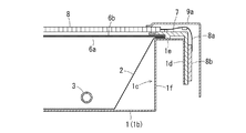
図1〜図5に示す実施形態の液晶モジュールは薄型液晶テレビに組み込まれる直下ライト型の液晶モジュールであって、リアフレーム1、光反射シート2、U字状冷陰極管3、ランプホルダー4、ランプフレーム5、光学シート6a,6b、セルガイド7、液晶パネル8、ベゼル9a,9bなどの主要部品で構成されている。
The liquid crystal module of the embodiment shown in FIGS. 1 to 5 is a direct light type liquid crystal module incorporated in a thin liquid crystal television, and includes a
この液晶モジュールの全体構成を概説すると、リアフレーム1は板金を曲げ加工して製作された浅い箱型フレームであって、その内部には光反射シート2が設けられている。そして、この光反射シート2の上には、光源として複数本(この実施形態では2本)のU字状冷陰極管3が平行に配設されており、これらのU字状冷陰極管3は複数(この実施形態では2つ)のランプホルダー4で保持されている。これらのランプホルダー4は、図1に示すようにU字状冷陰極管3を嵌合保持する保持部4aが形成されたものであって、U字状冷陰極管3の中央部を保持するランプホルダー4には、光学シート6aを下方から支持して撓みを防止するポスト4bが形成されている。
An outline of the overall configuration of the liquid crystal module is as follows. The
それぞれのU字状冷陰極管3の端部にはランプソケット3aが取付けられており、これらのランプソケット3aは、リアフレーム1の一方の短辺に沿った側板1a(この実施形態では右側の側板)に沿って底板1bに形成されたソケット嵌着用開口部(図には表れていない)に嵌着されている。そして、それぞれのランプソケット3aからU字状冷陰極管3のリード線3bがリアフレーム1の裏側へ引き出されている。
A
図2,図4に示すように、リアフレーム1の左右の短辺に沿って形成された側板1a,1aの内側には、合成樹脂製のランプフレーム5,5が取付けられている。このランプフレーム5は、天板部5aと前面傾斜板部5bと背板部5cとからなる中空フレームであって、このランプフレーム5でU字状冷陰極管3のランプソケット3aを取付けた両端部と、反対側の屈曲部を覆い隠すことによって、液晶パネル9の表示面の左右両側部に明るさのムラが生じないようにしている。そして、このランプフレーム5の天板部5aには、後述する光学シート6a,6bの端縁を挿入する凹溝部5dが形成されている。
As shown in FIGS. 2 and 4,
リアフレーム1の上端開口には、2枚の光学シート(光拡散シート)6a,6bが配置されており、この光学シート6a,6bの長辺沿いの端縁は、図3に示すように、リアフレーム1の長辺に形成された二重側板1c(ほぼ逆U字状に曲げ加工された二重側板)に載置されて、合成樹脂製のセルガイド7で押えられている。そして、光学シート6a,6bの短辺沿いの端縁は、図4に示すように、ランプフレーム5の天板部5aに形成された凹溝部5dに挿入されている。
Two optical sheets (light diffusion sheets) 6a and 6b are arranged at the upper end opening of the
光学シート6a,6bの上方には液晶パネル8が配置されており、図3,図4に示すように、この液晶パネル8の四周端縁はセルガイド7とランプフレーム5の上面に載置されている。そして、図1,図2に示すように、板金製の長短4本のベゼル9a,9a,9b,9bが、液晶パネル8の四周端縁とリアフレーム1の四周の側板を囲むように方形枠状に連結され、ビスでリアフレーム1の二重側板1c,1cの上端フランジ部の両端部に固定されている。
A
図1に示すように、液晶パネル8の長辺には、ソースドライバICチップを搭載したチップオンフィルム8aを介してX−配線基板8bが接続されており、このX−配線基板8bは、図3に示すようにリアフレーム1の二重側板1cに取付けたセルガイド7に固定されている。また、液晶パネル8の短辺には、ゲートドライバICチップを搭載したチップオンフィルム8cを介してY−配線基板8d接続されており、このY−配線基板8dは、図示はしていないが、リアフレーム1の短辺に沿った側板1aに固定されている。
As shown in FIG. 1, an
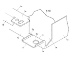
図1,図5に示すように、リアフレーム1の長辺に沿った二重側板1cの両端部は、外板部1dと上端フランジ部1eが切り欠かれ、両端部に残った内板部1jの略上半分が曲げ加工により外方へ直角に折り曲げられて取付用フランジ片1fが形成されている。この取付用フランジ片1fは、組み立てた液晶モジュールを電子機器のキャビネットに取付けるためのフランジ片であって、該フランジ片1fの両側端には補強用の立上り縁1g,1hが曲げ加工で形成されており、一方の立上り縁1hは取付用フランジ片1fの折曲げ部分1iで直角に折れ曲がって、二重側板1cの内板部1jの端まで下降して延びている。また、この取付用フランジ片1fには止具挿通穴1kが形成されている。このような取付用フランジ片1fは、リアフレーム1の相対向する長辺に沿った二重側板1c,1cの内板部1jの両端部に一箇所ずつ、合計四箇所に形成されている。
As shown in FIG. 1 and FIG. 5, both end portions of the
上記の取付用フランジ片1fは、両側端に形成された立上り縁1g,1hによって取付用フランジ片1f自体の強度が大幅に高められており、かつ、直角に折れ曲がって内板部1jの端まで延びる一方の立上り縁1hによって取付用フランジ片1fの折曲げ部分1iの強度も大幅に高められている。そのため、振動や衝撃力をうけても、取付用フランジ片1f自体が変形し難く、折曲げ部分1iの角度(折曲げ角度)も変化し難くなっている。
In the mounting
取付用フランジ片1fの強度は、補強用の立上り縁1g,1hの高さ寸法が大きくなるほど向上するが、あまり高くなると、一方の立上り縁1hの曲げ加工がし辛くなるので、立上り縁1g,1hの高さ寸法は、リアフレーム1の材料となる板金の厚さ寸法の2〜5倍程度に設定することが望ましい。参考までに、立上り縁1g,1hの高さ寸法を上記の程度にすると、取付用フランジ片1fの強度は、従来の絞り加工による取付用フランジ部104の強度に比べて40%以上向上することが確認された。
The strength of the mounting
また、図5に示すように、リアフレーム1の相対向する短辺に沿った側板1aの両端部には切欠き部1mが形成されている。斯かる切欠き部1mが形成されていると、切欠き部1mを利用して曲げ加工装置により取付用フランジ片1fの曲げ加工を容易に行うことができる利点があるので望ましい。
Moreover, as shown in FIG. 5, the
更に、両端が直角に曲がった短い方のベゼル9b,9bの両端コーナ部には、図1,図2に示すごとく、リアフレーム1の取付用フランジ片1fを避けるように凹入部9c,9cが形成されており、この凹入部9cに電子機器のフロントキャビネット裏面のボス部を嵌め込んで取付用フランジ片1fに重ね合わせると共に、取付用フランジ片1fの止具挿通穴1kからネジを該ボス部にねじ込むことによって、フロントキャビネットの開口部に液晶モジュールを取付けることができるようになっている。
Further, as shown in FIGS. 1 and 2, recessed
以上のような構成の液晶モジュールは、リアフレーム1の長辺に沿った二重側板1cの両端部に形成された取付用フランジ片1fが、単に外方へ直角に折れ曲がるだけのフランジ片ではなく、フランジ片1fの両側端に形成された立上り縁1g,1hによってフランジ片1f自体の強度が高められ、かつ、直角に折れ曲がって二重側板1cの内板部1jの端まで延びる一方の立上り縁1hによってフランジ片1fの折曲げ部分1iの強度も高められたものであるため、輸送時に振動や衝撃力を受けても、フランジ片1f自体が変形し難く、折曲げ部分1iの曲げ角度も変化し難い。そのため、液晶モジュールの組立作業やキャビネットへの取付作業を容易かつ正確に行うことができ、また、液晶モジュールの組立時においても取付用フランジ部1fの変形や曲げ角度の変化などが生じ難いので、歩留まりが良くなり、結果的にコストを低減することが可能となる。
The liquid crystal module configured as described above is not a flange piece in which the mounting
また、上記のように直角に折れ曲がる取付用フランジ片1fは、その折曲げ部分1iの位置を変えるだけで取付用フランジ片1fの高さ位置を自由に変更できるため、従来の絞り加工による取付用フランジ部104のように、電子機器のキャビネットに対する液晶モジュールの取付け高さが制限されるという問題を解消することもできる。
Further, the mounting
1 リアフレーム
1a リアフレームの短辺に沿った側板
1c リアフレームの長辺に沿った側板(二重側板)
1f 取付用フランジ片
1g,1h 取付用フランジ片の両側端の補強用の立上り縁
1h 直角に折れ曲がって側板の端まで延びる一方の立上り縁
1j 二重側板の内板部
1k 止具挿通穴
1m 切欠き部
2 光反射シート
3 線状光源(U字状冷陰極管)
5 ランプフレーム
6a,6b 光学シート
8 液晶パネル
9a,9b ベゼル
1
1f Mounting
5
Claims (2)
リアフレームの長辺に沿った側板の両端部に、外方へ直角に折れ曲がる取付用フランジ片であって、その両側端に補強用の立上り縁を有し、一方の立上り縁が直角に折れ曲がって側板の端まで延びる取付用フランジ片を、曲げ加工によって形成したことを特徴とする液晶モジュール。 In the liquid crystal module in which the light source is arranged inside the shallow box-shaped rear frame made of sheet metal, the liquid crystal panel is arranged in the upper end opening of the rear frame, and the four peripheral edges are surrounded by the bezel,
It is a mounting flange piece that bends outward at a right angle at both ends of the side plate along the long side of the rear frame, and has a rising edge for reinforcement at both ends, and one rising edge is bent at a right angle. A liquid crystal module, wherein a mounting flange piece extending to an end of a side plate is formed by bending.
Priority Applications (2)
| Application Number | Priority Date | Filing Date | Title |
|---|---|---|---|
| JP2011015950A JP2012155235A (en) | 2011-01-28 | 2011-01-28 | Liquid crystal module |
| US13/359,175 US20120194761A1 (en) | 2011-01-28 | 2012-01-26 | Liquid crystal module and display device |
Applications Claiming Priority (1)
| Application Number | Priority Date | Filing Date | Title |
|---|---|---|---|
| JP2011015950A JP2012155235A (en) | 2011-01-28 | 2011-01-28 | Liquid crystal module |
Publications (1)
| Publication Number | Publication Date |
|---|---|
| JP2012155235A true JP2012155235A (en) | 2012-08-16 |
Family
ID=46577098
Family Applications (1)
| Application Number | Title | Priority Date | Filing Date |
|---|---|---|---|
| JP2011015950A Pending JP2012155235A (en) | 2011-01-28 | 2011-01-28 | Liquid crystal module |
Country Status (2)
| Country | Link |
|---|---|
| US (1) | US20120194761A1 (en) |
| JP (1) | JP2012155235A (en) |
Cited By (2)
| Publication number | Priority date | Publication date | Assignee | Title |
|---|---|---|---|---|
| JP2018167816A (en) * | 2017-03-30 | 2018-11-01 | テイ・エス テック株式会社 | Support structure for vehicle seat |
| CN109765709A (en) * | 2019-03-14 | 2019-05-17 | 武汉三澍精密科技有限公司 | A kind of military low-temperature resistance display module |
Families Citing this family (3)
| Publication number | Priority date | Publication date | Assignee | Title |
|---|---|---|---|---|
| TWI432836B (en) * | 2011-01-28 | 2014-04-01 | Chunghwa Picture Tubes Ltd | Liquid crystal module and method for assembling the same |
| KR102043126B1 (en) * | 2013-03-29 | 2019-11-11 | 엘지디스플레이 주식회사 | Display apparatus |
| CN105652495A (en) * | 2016-01-21 | 2016-06-08 | 深圳市华星光电技术有限公司 | Displayer frame and displayer |
Family Cites Families (4)
| Publication number | Priority date | Publication date | Assignee | Title |
|---|---|---|---|---|
| KR100465796B1 (en) * | 2002-07-16 | 2005-01-13 | 삼성전자주식회사 | Display |
| JP4725116B2 (en) * | 2005-01-26 | 2011-07-13 | ソニー株式会社 | Display module |
| JP2009116189A (en) * | 2007-11-08 | 2009-05-28 | Funai Electric Co Ltd | Display |
| JP5304628B2 (en) * | 2009-12-22 | 2013-10-02 | 船井電機株式会社 | LCD module |
-
2011
- 2011-01-28 JP JP2011015950A patent/JP2012155235A/en active Pending
-
2012
- 2012-01-26 US US13/359,175 patent/US20120194761A1/en not_active Abandoned
Cited By (3)
| Publication number | Priority date | Publication date | Assignee | Title |
|---|---|---|---|---|
| JP2018167816A (en) * | 2017-03-30 | 2018-11-01 | テイ・エス テック株式会社 | Support structure for vehicle seat |
| CN109765709A (en) * | 2019-03-14 | 2019-05-17 | 武汉三澍精密科技有限公司 | A kind of military low-temperature resistance display module |
| CN109765709B (en) * | 2019-03-14 | 2024-03-29 | 武汉三澍精密科技有限公司 | For military use anti low temperature display module assembly |
Also Published As
| Publication number | Publication date |
|---|---|
| US20120194761A1 (en) | 2012-08-02 |
Similar Documents
| Publication | Publication Date | Title |
|---|---|---|
| US8477257B2 (en) | Liquid crystal module and display device | |
| US9467641B2 (en) | Television and electronic apparatus | |
| JP4915354B2 (en) | LCD module | |
| JP5304628B2 (en) | LCD module | |
| US20100296022A1 (en) | Liquid crystal module | |
| JP4380656B2 (en) | Liquid crystal display | |
| US8902376B2 (en) | Backlight module and display device using the same | |
| US9220174B2 (en) | Pedestal for flat panel display device and flat panel display device | |
| WO2020135267A1 (en) | Backlight module and display device | |
| US9635767B2 (en) | Flat panel display device | |
| JP2012155235A (en) | Liquid crystal module | |
| US8861190B2 (en) | Display device | |
| JP2011002657A (en) | Liquid crystal module | |
| JP2011227357A (en) | Thin display device | |
| US9507078B2 (en) | Black light module with mount and displaying apparatus therewith | |
| JP2012053119A (en) | Liquid crystal module | |
| WO2014069456A1 (en) | Display device | |
| US9445039B2 (en) | Flat-screen display device | |
| US9195085B2 (en) | Back plate capable of resisting external forces, backlight module having the same, and liquid crystal display using the same | |
| JP2014134595A (en) | Display device | |
| JP2010271662A (en) | Liquid crystal module | |
| US20120033143A1 (en) | Television and electronic apparatus | |
| TWM512169U (en) | Display module | |
| JP2009026611A (en) | Backlight device and display device | |
| WO2014125657A1 (en) | Electronic device |