WO2014119654A1 - 電子機器 - Google Patents
電子機器 Download PDFInfo
- Publication number
- WO2014119654A1 WO2014119654A1 PCT/JP2014/052064 JP2014052064W WO2014119654A1 WO 2014119654 A1 WO2014119654 A1 WO 2014119654A1 JP 2014052064 W JP2014052064 W JP 2014052064W WO 2014119654 A1 WO2014119654 A1 WO 2014119654A1
- Authority
- WO
- WIPO (PCT)
- Prior art keywords
- chassis
- metal plate
- sound
- main body
- opening
- Prior art date
- Legal status (The legal status is an assumption and is not a legal conclusion. Google has not performed a legal analysis and makes no representation as to the accuracy of the status listed.)
- Ceased
Links
Images

Classifications
-
- H—ELECTRICITY
- H04—ELECTRIC COMMUNICATION TECHNIQUE
- H04R—LOUDSPEAKERS, MICROPHONES, GRAMOPHONE PICK-UPS OR LIKE ACOUSTIC ELECTROMECHANICAL TRANSDUCERS; DEAF-AID SETS; PUBLIC ADDRESS SYSTEMS
- H04R1/00—Details of transducers, loudspeakers or microphones
- H04R1/02—Casings; Cabinets ; Supports therefor; Mountings therein
-
- H—ELECTRICITY
- H04—ELECTRIC COMMUNICATION TECHNIQUE
- H04M—TELEPHONIC COMMUNICATION
- H04M1/00—Substation equipment, e.g. for use by subscribers
- H04M1/02—Constructional features of telephone sets
- H04M1/03—Constructional features of telephone transmitters or receivers, e.g. telephone hand-sets
-
- H—ELECTRICITY
- H04—ELECTRIC COMMUNICATION TECHNIQUE
- H04R—LOUDSPEAKERS, MICROPHONES, GRAMOPHONE PICK-UPS OR LIKE ACOUSTIC ELECTROMECHANICAL TRANSDUCERS; DEAF-AID SETS; PUBLIC ADDRESS SYSTEMS
- H04R1/00—Details of transducers, loudspeakers or microphones
- H04R1/02—Casings; Cabinets ; Supports therefor; Mountings therein
- H04R1/025—Arrangements for fixing loudspeaker transducers, e.g. in a box, furniture
-
- H—ELECTRICITY
- H04—ELECTRIC COMMUNICATION TECHNIQUE
- H04M—TELEPHONIC COMMUNICATION
- H04M1/00—Substation equipment, e.g. for use by subscribers
- H04M1/02—Constructional features of telephone sets
- H04M1/03—Constructional features of telephone transmitters or receivers, e.g. telephone hand-sets
- H04M1/035—Improving the acoustic characteristics by means of constructional features of the housing, e.g. ribs, walls, resonating chambers or cavities
-
- H—ELECTRICITY
- H04—ELECTRIC COMMUNICATION TECHNIQUE
- H04R—LOUDSPEAKERS, MICROPHONES, GRAMOPHONE PICK-UPS OR LIKE ACOUSTIC ELECTROMECHANICAL TRANSDUCERS; DEAF-AID SETS; PUBLIC ADDRESS SYSTEMS
- H04R2499/00—Aspects covered by H04R or H04S not otherwise provided for in their subgroups
- H04R2499/10—General applications
- H04R2499/11—Transducers incorporated or for use in hand-held devices, e.g. mobile phones, PDA's, camera's
Definitions
- the present invention relates to an electronic device including an acoustic element that converts an electrical signal into sound or converts sound into an electrical signal.
- a mobile phone has a built-in speaker.
- the user is notified of an incoming call by ringing the speaker at the time of the incoming call.
- the thickness of the main body is increased by adding the thickness of the speaker and the thickness of the chassis.
- the thickness of the speaker is determined according to its structure and output, there is a limit to reducing the thickness.
- the chassis to which the speaker is attached and fixed greatly deforms due to the action of external force, the speaker may peel off from the chassis.
- the chassis needs to have a minimum thickness of, for example, about 0.8 mm in order to exhibit the necessary strength.
- the conventional mobile phone has a problem that it cannot be reduced in thickness because it is defined by the thickness of the main body portion in which the speaker is built.
- an object of the present invention is to reduce the thickness of an electronic device incorporating an acoustic element such as a speaker.
- an acoustic element that converts an electrical signal into sound or converts sound into an electrical signal is built in the main body.
- the chassis which comprises a main body, and the metal plate fixed to the surface of the said chassis so that the opening penetrated from the back surface of this chassis to the surface was plugged, and the said metal plate is in the center part.
- the thickness of the main body portion in which the acoustic element is built is determined by the total value of the thickness of the acoustic element itself and the thickness of the metal plate on which the acoustic element is fixed, and is synthesized.
- the thickness of the resin chassis is irrelevant.
- the main body can be made thinner by the difference between the thickness of the metal plate and the thickness of the synthetic resin chassis as compared with the conventional electronic device in which the acoustic element is fixed to the back surface of the chassis. .
- a double-sided adhesive tape having an opening in the center is interposed between the front surface of the chassis and the back surface of the metal plate, and the outer periphery of the back surface of the metal plate is formed on the surface of the chassis by the double-sided adhesive tape.
- the outer peripheral portion of the front surface of the acoustic element is fixed to the inner peripheral portion of the back surface of the metal plate.
- both the metal plate and the acoustic element can be fixed to the chassis with one double-sided adhesive tape.
- the metal plate is made of a magnetic material.
- the magnetic flux leaked forward from the acoustic element is absorbed by the metal plate, the adverse effect of the magnetic flux on the external device can be suppressed.
- the electronic device incorporating the acoustic element according to the present invention can be made thinner than before.
- FIG. 1 is a perspective view showing the surface of a mobile phone according to an embodiment of the present invention.
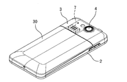
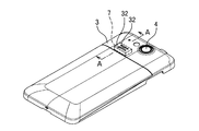
- FIG. 2 is a perspective view showing the back surface of the mobile phone.
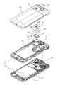
- FIG. 3 is an exploded perspective view of the mobile phone.
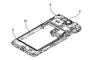
- FIG. 4 is a perspective view showing the surface of the back side main body portion.
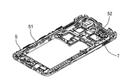
- FIG. 5 is a perspective view showing the back surface of the back-side main body portion.
- FIG. 6 is a perspective view showing a state in which the back-side main body portion is covered with the back-side cover panel.
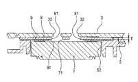
- FIG. 7 is an enlarged sectional view taken along line AA in FIG.
- a mobile phone includes a main body 1 including an incoming call notification speaker 7, a front-side cover panel 2 that covers the front and back surfaces of the main body 1, and A back side cover panel 3.
- the screen 10 is exposed from the front cover panel 2.
- the photographing lens 4 is exposed from the back cover panel 3.
- the back side cover panel 3 includes a detachable battery cover 30.
- the main body 1 includes a rear-side main body chassis 5 and a front-side main body chassis 6 made of synthetic resin and bonded and fixed to each other.
- the main body chassis is not limited to being made of synthetic resin, and may be made of metal, for example.
- the rear body chassis 5 is formed with a surrounding wall 51 that surrounds the storage chamber of the battery 11.
- An opening 52 in which the speaker 7 is to be installed is formed so as to penetrate from the rear surface to the front surface of the rear body chassis 5.
- a photographing lens 4 is provided on the side of the opening 52.
- a circuit board 61 is provided on the back surface of the front-side main body chassis 6.
- a camera 62 is arranged toward the photographing lens 4 of the back side main body chassis 5.
- a window 31 for exposing the photographing lens 4 is opened in the rear cover panel 3.
- Two sound emission holes 32 for releasing sound from the sound emission surface 71 provided on the front surface of the speaker 7 are provided.
- An installation surface 53 is formed on the surface of the back side body chassis 5 so as to surround the opening 52.
- a metal plate 8 such as stainless steel having two through holes 81, for example, international standard ISO 15510-4301-304-00-I (corresponding to Japanese Industrial Standard SUS304) is installed.
- a double-sided pressure-sensitive adhesive tape 9 having a central opening 91 is interposed between the surface of the back side main body chassis and the back surface of the metal plate. The outer peripheral portion of the back surface of the metal plate 8 is fixed to the installation surface 53 of the back-side main body chassis 5 by the double-sided adhesive tape 9.
- the double-sided adhesive tape 9 is affixed to the front outer peripheral region around the sound emitting surface 71 of the speaker 7 and is fixed to the inner peripheral portion of the back surface of the metal plate 8 via the double-sided adhesive tape 9.
- the metal plate 8 and the speaker 7 are fixed to the rear-side main body chassis (5).
- the speaker 7 is accommodated in the opening 52 of the back-side main body chassis 5 as a whole. Sound emitted from the sound emitting surface 71 passes through the central opening 91 of the double-sided adhesive tape 9, the two through holes 81 of the metal plate 8, and the two sound emitting holes 32 of the back side cover panel 3, and is emitted to the outside. Is done.
- the opening 52 is formed in the back-side body chassis 5 and the speaker 7 is fixed to the metal plate 8 installed so as to close the opening 52
- the difference between the thickness T (for example, 0.3 mm) of the metal plate 8 and the thickness (for example, 0.8 mm) of the back-side body chassis 5 is compared with the structure in which the speaker is fixed to the rear-side body chassis. Therefore, it is possible to reduce the thickness.
- the double-sided adhesive tape 9 functions as a waterproof packing, it is possible to suppress water from entering the inside of the main body 1 from the two sound emitting holes 32 of the back side cover panel 3 through the opening 52 of the back side main body chassis 5. .
- the configuration of each part of the present invention is not limited to the above embodiment, and various modifications can be made within the technical scope described in the claims.
- the speaker 7 that converts an electrical signal into sound is illustrated as an acoustic element, the present invention is not limited to the speaker 7 and can be implemented in a microphone mounting structure that converts sound into an electrical signal. As a result, the same effect as that of the speaker 7 mounting structure described above can be obtained.
- a film speaker may be used as the speaker.
- the present invention is not limited to a cellular phone, and can be implemented in various electronic devices that incorporate an acoustic element that converts an electrical signal into sound or converts sound into an electrical signal.
Landscapes
- Engineering & Computer Science (AREA)
- Signal Processing (AREA)
- Physics & Mathematics (AREA)
- Acoustics & Sound (AREA)
- Telephone Set Structure (AREA)
- Details Of Audible-Bandwidth Transducers (AREA)
Priority Applications (1)
| Application Number | Priority Date | Filing Date | Title |
|---|---|---|---|
| US14/805,186 US9451346B2 (en) | 2013-02-01 | 2015-07-21 | Electronic apparatus and chassis with incorporated sound device |
Applications Claiming Priority (2)
| Application Number | Priority Date | Filing Date | Title |
|---|---|---|---|
| JP2013-018008 | 2013-02-01 | ||
| JP2013018008A JP6301584B2 (ja) | 2013-02-01 | 2013-02-01 | 音響素子を内蔵した電子機器 |
Related Child Applications (1)
| Application Number | Title | Priority Date | Filing Date |
|---|---|---|---|
| US14/805,186 Continuation US9451346B2 (en) | 2013-02-01 | 2015-07-21 | Electronic apparatus and chassis with incorporated sound device |
Publications (1)
| Publication Number | Publication Date |
|---|---|
| WO2014119654A1 true WO2014119654A1 (ja) | 2014-08-07 |
Family
ID=51262365
Family Applications (1)
| Application Number | Title | Priority Date | Filing Date |
|---|---|---|---|
| PCT/JP2014/052064 Ceased WO2014119654A1 (ja) | 2013-02-01 | 2014-01-30 | 電子機器 |
Country Status (3)
| Country | Link |
|---|---|
| US (1) | US9451346B2 (enExample) |
| JP (1) | JP6301584B2 (enExample) |
| WO (1) | WO2014119654A1 (enExample) |
Families Citing this family (2)
| Publication number | Priority date | Publication date | Assignee | Title |
|---|---|---|---|---|
| JP6382648B2 (ja) * | 2014-09-01 | 2018-08-29 | 古野電気株式会社 | 音響構造 |
| CN204761633U (zh) * | 2015-06-10 | 2015-11-11 | 瑞声光电科技(常州)有限公司 | 发声器件 |
Citations (2)
| Publication number | Priority date | Publication date | Assignee | Title |
|---|---|---|---|---|
| JP2006060398A (ja) * | 2004-08-18 | 2006-03-02 | Fujitsu Ltd | 携帯端末装置 |
| JP2011029841A (ja) * | 2009-07-23 | 2011-02-10 | Nec Saitama Ltd | 携帯通信機器 |
Family Cites Families (4)
| Publication number | Priority date | Publication date | Assignee | Title |
|---|---|---|---|---|
| JP3490017B2 (ja) * | 1999-03-18 | 2004-01-26 | 松下電器産業株式会社 | 無線端末装置 |
| JP2010147551A (ja) * | 2008-12-16 | 2010-07-01 | Nec Corp | 筐体防水構造及び携帯機器 |
| JP5316498B2 (ja) * | 2010-08-23 | 2013-10-16 | 株式会社Jvcケンウッド | スピーカ搭載品 |
| JP2012227836A (ja) | 2011-04-21 | 2012-11-15 | Panasonic Corp | 携帯端末装置 |
-
2013
- 2013-02-01 JP JP2013018008A patent/JP6301584B2/ja not_active Expired - Fee Related
-
2014
- 2014-01-30 WO PCT/JP2014/052064 patent/WO2014119654A1/ja not_active Ceased
-
2015
- 2015-07-21 US US14/805,186 patent/US9451346B2/en not_active Expired - Fee Related
Patent Citations (2)
| Publication number | Priority date | Publication date | Assignee | Title |
|---|---|---|---|---|
| JP2006060398A (ja) * | 2004-08-18 | 2006-03-02 | Fujitsu Ltd | 携帯端末装置 |
| JP2011029841A (ja) * | 2009-07-23 | 2011-02-10 | Nec Saitama Ltd | 携帯通信機器 |
Also Published As
| Publication number | Publication date |
|---|---|
| US20150326961A1 (en) | 2015-11-12 |
| JP6301584B2 (ja) | 2018-03-28 |
| JP2014150404A (ja) | 2014-08-21 |
| US9451346B2 (en) | 2016-09-20 |
Similar Documents
| Publication | Publication Date | Title |
|---|---|---|
| EP2637389B1 (en) | Microphone Boot For A Portable Electronic Device | |
| US8295527B2 (en) | Microphone boot for a portable electronic device | |
| US9510097B1 (en) | Electronic device and waterproof sheet thereof | |
| WO2011080877A1 (ja) | スピーカ用振動板及びこれを用いたスピーカと携帯端末装置 | |
| JP5429879B2 (ja) | 携帯型電子機器および電気基板の支持部材 | |
| US7480209B2 (en) | Submersible loudspeaker assembly | |
| JP6415706B2 (ja) | 音響電子部品が内蔵された電子機器 | |
| JP2012160897A (ja) | 電子機器の防水構造 | |
| WO2014119654A1 (ja) | 電子機器 | |
| JP5316498B2 (ja) | スピーカ搭載品 | |
| JP2020018021A (ja) | 電気音響変換器、表示装置 | |
| JP5430462B2 (ja) | コンデンサマイクロホン用の出力コネクタおよびコンデンサマイクロホン | |
| JP2011029841A (ja) | 携帯通信機器 | |
| JP2013009094A (ja) | 防水構造及び電子機器、ならびに防水方法 | |
| JP2006067008A (ja) | スピーカ | |
| EP3644621A1 (en) | Active noise reduction loudspeaker component of headset | |
| JP6055671B2 (ja) | 電子機器 | |
| JP2015186165A (ja) | 携帯端末 | |
| JP2013157764A (ja) | 電子機器 | |
| JP2008141317A (ja) | スピーカ | |
| JP5969553B2 (ja) | 電子機器 | |
| CN111083601A (zh) | 电子设备 | |
| JP2013183261A (ja) | 電気音響変換装置を備えた電子機器 | |
| JP2009010565A (ja) | 発音体および電子機器 |
Legal Events
| Date | Code | Title | Description |
|---|---|---|---|
| 121 | Ep: the epo has been informed by wipo that ep was designated in this application |
Ref document number: 14746436 Country of ref document: EP Kind code of ref document: A1 |
|
| NENP | Non-entry into the national phase |
Ref country code: DE |
|
| 122 | Ep: pct application non-entry in european phase |
Ref document number: 14746436 Country of ref document: EP Kind code of ref document: A1 |