WO2014119308A1 - 密閉型電池 - Google Patents
密閉型電池 Download PDFInfo
- Publication number
- WO2014119308A1 WO2014119308A1 PCT/JP2014/000471 JP2014000471W WO2014119308A1 WO 2014119308 A1 WO2014119308 A1 WO 2014119308A1 JP 2014000471 W JP2014000471 W JP 2014000471W WO 2014119308 A1 WO2014119308 A1 WO 2014119308A1
- Authority
- WO
- WIPO (PCT)
- Prior art keywords
- sealing plate
- battery
- sealed battery
- sealed
- plate
- Prior art date
- Legal status (The legal status is an assumption and is not a legal conclusion. Google has not performed a legal analysis and makes no representation as to the accuracy of the status listed.)
- Ceased
Links
Images





Classifications
-
- H—ELECTRICITY
- H01—ELECTRIC ELEMENTS
- H01M—PROCESSES OR MEANS, e.g. BATTERIES, FOR THE DIRECT CONVERSION OF CHEMICAL ENERGY INTO ELECTRICAL ENERGY
- H01M4/00—Electrodes
- H01M4/02—Electrodes composed of, or comprising, active material
- H01M4/36—Selection of substances as active materials, active masses, active liquids
- H01M4/48—Selection of substances as active materials, active masses, active liquids of inorganic oxides or hydroxides
- H01M4/52—Selection of substances as active materials, active masses, active liquids of inorganic oxides or hydroxides of nickel, cobalt or iron
- H01M4/525—Selection of substances as active materials, active masses, active liquids of inorganic oxides or hydroxides of nickel, cobalt or iron of mixed oxides or hydroxides containing iron, cobalt or nickel for inserting or intercalating light metals, e.g. LiNiO2, LiCoO2 or LiCoOxFy
-
- H—ELECTRICITY
- H01—ELECTRIC ELEMENTS
- H01M—PROCESSES OR MEANS, e.g. BATTERIES, FOR THE DIRECT CONVERSION OF CHEMICAL ENERGY INTO ELECTRICAL ENERGY
- H01M10/00—Secondary cells; Manufacture thereof
- H01M10/05—Accumulators with non-aqueous electrolyte
- H01M10/052—Li-accumulators
-
- H—ELECTRICITY
- H01—ELECTRIC ELEMENTS
- H01M—PROCESSES OR MEANS, e.g. BATTERIES, FOR THE DIRECT CONVERSION OF CHEMICAL ENERGY INTO ELECTRICAL ENERGY
- H01M10/00—Secondary cells; Manufacture thereof
- H01M10/05—Accumulators with non-aqueous electrolyte
- H01M10/052—Li-accumulators
- H01M10/0525—Rocking-chair batteries, i.e. batteries with lithium insertion or intercalation in both electrodes; Lithium-ion batteries
-
- H—ELECTRICITY
- H01—ELECTRIC ELEMENTS
- H01M—PROCESSES OR MEANS, e.g. BATTERIES, FOR THE DIRECT CONVERSION OF CHEMICAL ENERGY INTO ELECTRICAL ENERGY
- H01M10/00—Secondary cells; Manufacture thereof
- H01M10/05—Accumulators with non-aqueous electrolyte
- H01M10/058—Construction or manufacture
- H01M10/0587—Construction or manufacture of accumulators having only wound construction elements, i.e. wound positive electrodes, wound negative electrodes and wound separators
-
- H—ELECTRICITY
- H01—ELECTRIC ELEMENTS
- H01M—PROCESSES OR MEANS, e.g. BATTERIES, FOR THE DIRECT CONVERSION OF CHEMICAL ENERGY INTO ELECTRICAL ENERGY
- H01M50/00—Constructional details or processes of manufacture of the non-active parts of electrochemical cells other than fuel cells, e.g. hybrid cells
- H01M50/10—Primary casings; Jackets or wrappings
- H01M50/147—Lids or covers
- H01M50/166—Lids or covers characterised by the methods of assembling casings with lids
- H01M50/167—Lids or covers characterised by the methods of assembling casings with lids by crimping
-
- H—ELECTRICITY
- H01—ELECTRIC ELEMENTS
- H01M—PROCESSES OR MEANS, e.g. BATTERIES, FOR THE DIRECT CONVERSION OF CHEMICAL ENERGY INTO ELECTRICAL ENERGY
- H01M50/00—Constructional details or processes of manufacture of the non-active parts of electrochemical cells other than fuel cells, e.g. hybrid cells
- H01M50/10—Primary casings; Jackets or wrappings
- H01M50/147—Lids or covers
- H01M50/166—Lids or covers characterised by the methods of assembling casings with lids
- H01M50/171—Lids or covers characterised by the methods of assembling casings with lids using adhesives or sealing agents
-
- H—ELECTRICITY
- H01—ELECTRIC ELEMENTS
- H01M—PROCESSES OR MEANS, e.g. BATTERIES, FOR THE DIRECT CONVERSION OF CHEMICAL ENERGY INTO ELECTRICAL ENERGY
- H01M50/00—Constructional details or processes of manufacture of the non-active parts of electrochemical cells other than fuel cells, e.g. hybrid cells
- H01M50/30—Arrangements for facilitating escape of gases
- H01M50/317—Re-sealable arrangements
- H01M50/325—Re-sealable arrangements comprising deformable valve members, e.g. elastic or flexible valve members
-
- H—ELECTRICITY
- H01—ELECTRIC ELEMENTS
- H01M—PROCESSES OR MEANS, e.g. BATTERIES, FOR THE DIRECT CONVERSION OF CHEMICAL ENERGY INTO ELECTRICAL ENERGY
- H01M50/00—Constructional details or processes of manufacture of the non-active parts of electrochemical cells other than fuel cells, e.g. hybrid cells
- H01M50/30—Arrangements for facilitating escape of gases
- H01M50/342—Non-re-sealable arrangements
- H01M50/3425—Non-re-sealable arrangements in the form of rupturable membranes or weakened parts, e.g. pierced with the aid of a sharp member
-
- H—ELECTRICITY
- H01—ELECTRIC ELEMENTS
- H01M—PROCESSES OR MEANS, e.g. BATTERIES, FOR THE DIRECT CONVERSION OF CHEMICAL ENERGY INTO ELECTRICAL ENERGY
- H01M50/00—Constructional details or processes of manufacture of the non-active parts of electrochemical cells other than fuel cells, e.g. hybrid cells
- H01M50/50—Current conducting connections for cells or batteries
- H01M50/572—Means for preventing undesired use or discharge
- H01M50/574—Devices or arrangements for the interruption of current
- H01M50/578—Devices or arrangements for the interruption of current in response to pressure
-
- H—ELECTRICITY
- H01—ELECTRIC ELEMENTS
- H01M—PROCESSES OR MEANS, e.g. BATTERIES, FOR THE DIRECT CONVERSION OF CHEMICAL ENERGY INTO ELECTRICAL ENERGY
- H01M2200/00—Safety devices for primary or secondary batteries
- H01M2200/20—Pressure-sensitive devices
-
- H—ELECTRICITY
- H01—ELECTRIC ELEMENTS
- H01M—PROCESSES OR MEANS, e.g. BATTERIES, FOR THE DIRECT CONVERSION OF CHEMICAL ENERGY INTO ELECTRICAL ENERGY
- H01M50/00—Constructional details or processes of manufacture of the non-active parts of electrochemical cells other than fuel cells, e.g. hybrid cells
- H01M50/10—Primary casings; Jackets or wrappings
- H01M50/147—Lids or covers
-
- Y—GENERAL TAGGING OF NEW TECHNOLOGICAL DEVELOPMENTS; GENERAL TAGGING OF CROSS-SECTIONAL TECHNOLOGIES SPANNING OVER SEVERAL SECTIONS OF THE IPC; TECHNICAL SUBJECTS COVERED BY FORMER USPC CROSS-REFERENCE ART COLLECTIONS [XRACs] AND DIGESTS
- Y02—TECHNOLOGIES OR APPLICATIONS FOR MITIGATION OR ADAPTATION AGAINST CLIMATE CHANGE
- Y02E—REDUCTION OF GREENHOUSE GAS [GHG] EMISSIONS, RELATED TO ENERGY GENERATION, TRANSMISSION OR DISTRIBUTION
- Y02E60/00—Enabling technologies; Technologies with a potential or indirect contribution to GHG emissions mitigation
- Y02E60/10—Energy storage using batteries
-
- Y—GENERAL TAGGING OF NEW TECHNOLOGICAL DEVELOPMENTS; GENERAL TAGGING OF CROSS-SECTIONAL TECHNOLOGIES SPANNING OVER SEVERAL SECTIONS OF THE IPC; TECHNICAL SUBJECTS COVERED BY FORMER USPC CROSS-REFERENCE ART COLLECTIONS [XRACs] AND DIGESTS
- Y02—TECHNOLOGIES OR APPLICATIONS FOR MITIGATION OR ADAPTATION AGAINST CLIMATE CHANGE
- Y02P—CLIMATE CHANGE MITIGATION TECHNOLOGIES IN THE PRODUCTION OR PROCESSING OF GOODS
- Y02P70/00—Climate change mitigation technologies in the production process for final industrial or consumer products
- Y02P70/50—Manufacturing or production processes characterised by the final manufactured product
Definitions
- the present invention relates to a sealed battery, and more particularly to a sealed battery having a gas discharge function.
- lithium ion secondary batteries Since lithium ion secondary batteries have high energy density and high capacity, they are widely used as driving power sources for mobile information terminals such as mobile phones and notebook computers. Recently, lithium ion secondary batteries are expected to be used in applications requiring high voltage and high capacity, such as drive power sources for battery-powered automobiles and household power storage systems.
- FIG. 9 is a cross-sectional view showing a sealing member having a conventional structure.
- the sealing body of the sealed battery includes a pair of explosion-proof valves each provided with a valve cap 21 provided with a vent hole 21a, a PTC thermistor 22, and crushing grooves 23a and 25a that crush when the battery internal pressure rises. 23, 25, an insulating plate 24 that prevents electrical conduction between the outer peripheral portions of the pair of explosion-proof valves 23, 25, and a terminal plate 26 that is provided with a gas vent hole 26a and is electrically connected to the positive electrode plate. I have. In this technique, when the battery internal pressure rises, first, the electrical contact between the pair of explosion-proof valves 23 and 25 is cut, and the energization to the valve cap 21 is cut off.
- Patent Documents 1 to 3 technologies relating to the improvement of battery safety.
- Patent Document 1 the release portion formed by the scratch on the battery terminal is ruptured when the internal battery pressure exceeds a predetermined battery operating range, the breakable electrical connector is broken, and the connector plate and the battery terminal Discloses a technology relating to a battery interconnection stem that disconnects the electrical connection between the two. According to this technology, a system for integrating the battery release characteristics with means for simultaneously disconnecting cells from the battery pack and thereby isolating the cells can be realized.
- Patent Document 2 discloses a technique in which a sealing plate is formed with an annular groove divided by a connecting portion, and the connecting portions are provided in at least two places. According to this technology, when the internal pressure of the battery is abnormally increased, a break in the groove is surely generated, but with a small impact, a non-aqueous secondary battery that does not inadvertently break in the groove can be realized. .
- Patent Document 3 discloses a self-recovering first safety valve that can be repeatedly opened and closed, a slit formed in an annular shape leaving a hinge portion, and a thermoplastic resin that hermetically closes the slit. And a safety valve comprising a second safety valve that is configured such that the opening pressure of the second safety valve is set higher than the first safety valve and lower than the pressure at which the sealing portion of the battery case is damaged, and The second safety valve discloses that the thermoplastic resin is broken and the portion surrounded by the slit is bent at the hinge portion to open. According to this technique, the first safety valve that self-recovers can be reused even after the battery internal pressure rises, and further, the battery case can be effectively prevented from rupture with the second safety valve that does not self-reset.
- This invention solves the said subject, and aims at providing the sealed battery which can discharge
- the present invention for solving the above problems is a sealed battery in which the opening of a bottomed cylindrical outer can is caulked and sealed with a sealing plate via an insulating gasket, and the sealing plate includes a battery internal pressure.
- a thin-walled portion that serves as a starting point for deformation of the sealing plate when raised, and when the internal pressure of the battery rises, a gap is generated between the insulating gasket and the sealing plate due to deformation of the sealing plate, and the gas inside the outer can It is discharged outside the outer can.
- FIG. 1 is a cross-sectional view of a sealed battery according to the present invention
- FIG. 2 is a diagram for explaining deformation due to an increase in internal pressure of a sealing portion of the sealed battery according to the present invention.
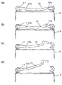
- the sealing plate 10 of the sealed battery according to the present invention is provided with a thin-walled portion 10a that is thinner than other portions, thereby reducing the strength of the portion. ing. For this reason, when the battery internal pressure rises, the sealing plate 10 is deformed starting from the thin portion 10a (see FIGS. 2A and 2B). Then, when the deformation of the sealing plate 10 proceeds, the contact between the insulating gasket 11 and the sealing plate 10 is loosened, and a gap capable of discharging gas is generated between the sealing plate 10 and the insulating gasket 11 (FIG. 2 (c), ( d)).
- the gas exhaust capability can sufficiently follow. Therefore, there is no possibility that damage due to internal pressure is applied to the side wall of the outer can 5 after the opening is formed, and cracks on the side wall of the outer can 5 can be remarkably suppressed. Thereby, the discharge direction of the gas inside the outer can 5 or the electrolyte can be guided only to the sealing plate 10 side. For this reason, it is prevented that the member adjacent to the side wall direction of the outer can 10 is adversely affected.
- the sealed battery according to the present invention is used for an assembled battery, even if an abnormality occurs in one unit cell, It is prevented that the safety of other cells constituting the assembled battery is impaired.
- the sealing plate is formed of a single plate-like member.
- the sealing plate 10 is a single plate-like member, the sealing plate 10 can be easily deformed when the internal pressure is increased, the separation from the insulating gasket 11 can be accelerated, and the manufacturing of the sealing plate 10 is simplified.
- the single plate-like member may be substantially constituted by a single plate, for example, a single clad material in which a plurality of materials are bonded and integrated. Also good. Further, the plate-like member may have a constant thickness, may have a change in thickness, or may be formed with one or more stepped portions 10b for the purpose of increasing the strength. Moreover, the structure etc. to which the member used as the contact of a connection with the element outside a battery is partially added may be sufficient.
- the sealing plate can be made of aluminum or an aluminum alloy.
- Aluminum or aluminum alloy is suitable as a material for the sealing plate because it is lightweight, easily deformed, and has high resistance to an electrolytic solution.
- the said structure WHEREIN The grooved part which protruded in the battery axial direction is provided in the side wall of the said exterior can,
- the said thin part can be set as the structure provided in the inner peripheral side rather than the said grooved part.
- a groove portion 5a protruding in the battery axial direction is often provided on the side wall of the outer can 5; however, the pressure inside the battery is almost not in the sealing plate portion outside the groove portion 5a. Since it does not act, when the thin part 10a is provided in this part, there exists a possibility that the effect of this invention may become small. For this reason, when forming the grooving part 5a, it is preferable that the thin part 10a is provided including the sealing plate part inside the grooving part 5a, and only in the sealing plate part inside the grooving part 5a. More preferably.
- the entire sealing plate 10 is in a position lower than the top surface of the outer can 5.
- space efficiency can be enhanced and direct impact can be suppressed from acting on the sealing plate 10. Can be suppressed.
- the said structure is achieved by providing the convex level
- this invention is not limited to this structure.
- the sealing plate 10 may have a flat configuration without a step, and may include a convex step portion outside the battery.
- step-difference part convex in the same direction or convex in a different direction may be sufficient.
- the sealing plate can be completely detached from the outer can as the battery internal pressure increases.
- This configuration is preferable because the opening area for discharging gas can be greatly increased.
- the sealed battery is a lithium ion secondary battery having a positive electrode plate, and the positive electrode plate has a general formula Li x Ni y M 1-y O 2 (0.95 ⁇ x ⁇ 1.10.
- M includes at least one of Co, Mn, Cr, Fe, Mg, Ti and Al, and a lithium nickel composite oxide represented by 0.6 ⁇ y ⁇ 0.95) as a positive electrode active material, and the sealed battery
- the volume energy density may be 500 Wh / L or more.
- the lithium nickel composite oxide has a larger capacity, higher energy density, and lower cost than the lithium cobalt composite oxide (LiCoO 2 ) that has been used as a positive electrode active material for lithium ion secondary batteries.
- a battery having a high energy density with a volume energy density of 500 Wh / L or more can be obtained at low cost.
- the mass of the lithium nickel composite oxide is preferably 50% by mass or more of the total mass of the positive electrode active material, more preferably 80% by mass or more, and further preferably 100% by mass.
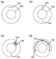
- the number of the thin-walled portions 10a may be one as shown in FIGS. 3 to 5, or may be two or more.
- the planar shape of the thin portion is not particularly limited, and may be, for example, a linear shape such as a straight line or a curved shape, or a planar shape such as a polygon, a circle, or any other irregular shape. Or a combination thereof.
- positioning may be regular (equal intervals with the same size), random arrangement
- the thin-walled portion 10 a can be configured to have one or a plurality of straight lines.
- the straight line may be a straight line along the diameter of the sealing plate 10 as shown in FIG. 3A, or a straight line that does not follow the diameter of the sealing plate 10 as shown in FIG. It may be a shape.
- the sealing plate 10 may be arranged evenly (at equal intervals), as shown in FIG. 3 (d). In this way, the configuration may be unevenly (randomly) arranged.
- the thin part 10a can be set as the structure which is 1 or several curve shape.
- the curved shape may be concentric with the outer peripheral line of the sealing plate 10 (see FIG. 4A) or concentric arc shape (see FIG. 4B), and concentric with the outer peripheral line of the sealing plate 10.
- there may be a plurality of curved shapes see FIGS. 4C and 4D).
- the thin portion 10a can be configured to be planar.
- the planar shape is not particularly limited, and may be a polygon (see FIG. 5A), a circle, an ellipse, a sector, or any other irregular shape (see FIG. 5B).
- the thin portion may be a combination of a linear shape, a curved shape, and a planar shape.
- the some thin part 10a may be the structure which a part overlaps (refer FIG.5 (c)), and the structure (refer FIG.5 (d)) which does not overlap may be sufficient.
- the cross-sectional shape of the thin portion is not particularly limited.
- the cross-sectional shape may be a V-shaped (triangular) shape, a quadrangular shape, a U-shape, a semicircular shape, etc., and the groove depth is constant. Or may change.
- the structure provided with the flat surface parallel to a sealing board surface may be sufficient, and the structure provided with the uneven surface which has regular unevenness
- corrugation may be sufficient.
- the corner portion of the concave portion is configured to have an obtuse angle or R
- the thin portion is configured to be a concave portion formed on the inner surface of the battery, or the remaining thickness of the thin portion It is preferable to make the thickness difficult to break.
- the thin portion 10a may be formed by providing a recess in the inside surface of the battery of the sealing plate 10, but FIG. 6 (a).
- the sealing plate 10 may be formed by providing a recess on the outer surface of the battery.
- the sealing plate 10 may be formed by providing recesses on both sides.
- the thin-walled portion 10a is indicated by a broken line when a concave portion is provided on the outer side of the battery.
- the concave portions formed on both surfaces may be aligned when the sealing plate 10 is seen through the plane (see FIG. 7 (d)).
- the concave portions formed may be arranged so as not to overlap (see FIG. 6C and FIG. 7C), or may be arranged so that a part of the concave portions formed on both surfaces are overlapped (FIG. 6 ( d)).
- the arrangement of the thin portion 10a is not particularly limited.
- the portion caulked by the insulating gasket 11 is not deformed when the internal pressure is increased. Therefore, if a thin wall portion is provided in this portion, the sealing plate is a starting point for deformation of the sealing plate when the battery internal pressure is increased in the present invention.
- the sealing plate is a starting point for deformation of the sealing plate when the battery internal pressure is increased in the present invention.
- the sealing reliability may be impaired. Therefore, it is preferable that there is no thin portion in the caulked portion of the sealing plate 10.
- step-difference part 10b in the sealing board 10 it is preferable that at least one part of the thin part 10a exists in an outer side part from the level
- the method for forming the thin-walled portion is not particularly limited, but it is preferable because it is easy to form by pressing.
- the sealing plate also has a configuration that also serves as one of the external terminals of the positive and negative electrodes of the battery.
- the battery structure can be simplified.
- the outer can is preferably configured to serve as the other external terminal.
- a sealed battery that can discharge gas only from the sealing plate side can be realized.
- This sealed battery does not adversely affect the member where the side wall of the outer can is arranged on the alligator, and does not hinder the safety of other batteries when applied to, for example, an assembled battery.
- FIG. 1 is a cross-sectional view of a sealed battery according to the present invention.
- FIG. 2 is a partially enlarged cross-sectional view for explaining deformation due to an increase in internal pressure of the sealing portion of the sealed battery according to the present invention.
- FIG. 3 is a bottom view showing an example of arrangement of the thin portion of the sealing plate.
- FIG. 4 is a bottom view showing a modified example of the arrangement of the thin portion of the sealing plate.
- FIG. 5 is a bottom view showing a further modification of the arrangement of the thin portion of the sealing plate.
- FIG. 6 is a bottom perspective view of the arrangement of the thin portion when a thin portion is provided on at least the outside of the battery on the sealing plate.
- FIG. 7 is a cross-sectional view showing a modified example of the arrangement of the thin portion of the sealing plate.
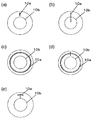
- FIG. 8 is a bottom view showing the arrangement of the thin portion of the sealing plate in the embodiment.
- FIG. 8 (a) shows Embodiments 1 to 3
- FIG. 8 (b) shows Embodiments 4 to 6, and
- FIG. 8 (c) Shows Examples 7 to 9,
- FIG. 8D shows Examples 10 to 12, and
- FIG. 8E shows Examples 13 to 15, respectively.
- FIG. 1 is a cross-sectional view of a sealed battery according to the present invention
- FIG. 2 is a partially enlarged cross-sectional view for explaining deformation due to an increase in internal pressure of a sealing portion of the sealed battery according to the present invention.
- the nonaqueous electrolyte secondary battery includes a wound electrode group 4 in which a positive electrode plate 1 and a negative electrode plate 2 are wound in a spiral shape with a separator 3 interposed therebetween.
- the wound electrode group 4 has insulating plates 6 and 7 arranged on the upper and lower sides, respectively, and is housed inside a bottomed cylindrical metal outer can 5.
- a non-aqueous electrolyte (not shown) is injected inside the outer can 5, and the opening of the outer can 5 is sealed by caulking with a sealing plate 10 via a gasket 11. .
- the lead 9 of the negative electrode plate 2 is welded to the inner bottom portion of the outer can 5, and the lead 8 of the positive electrode plate 1 is welded to the lower surface of the sealing plate 10.
- the outer can 5 functions as a negative electrode external terminal
- the sealing plate 10 functions as a positive electrode external terminal.
- the periphery of the upper insulating plate 6 is held by a grooving portion 5a formed on the side wall of the outer can 5, and the wound electrode group 4 is fixed from above.
- the sealing plate 10 is provided with a thin portion 10a having a thinner plate thickness than the other portions, thereby reducing the strength of the thin portion 10a. For this reason, when the battery internal pressure rises, the sealing plate 10 is deformed starting from the thin portion 10a (see FIGS. 2A and 2B). Then, when the deformation of the sealing plate 10 proceeds, the caulking seal between the insulating gasket 11 and the sealing plate 10 is loosened, and a gap capable of discharging gas is generated between the sealing plate 10 and the insulating gasket 11 (FIG. 2 (c), (See (d)). When the battery internal pressure further increases, the sealing plate 10 is detached from the outer can 5.
- the gas exhaust capability can sufficiently follow even if gas is rapidly generated, and there is no risk of damage caused by internal pressure on the side wall of the outer can 5 after the opening is formed, Generation of cracks on the side wall of the outer can 5 can be suppressed.
- the discharge direction of the gas inside the outer can and the electrolyte can be guided only to the sealing plate side. For this reason, it is prevented that the member adjacent to the outer can side wall direction is adversely affected.
- the sealed battery according to the present invention is used for an assembled battery, even if an abnormality occurs in one unit cell, the assembled battery It is prevented that the safety of other batteries constituting the battery is impaired.
- the sealing plate 10 is preferably composed of a single plate-like member made of aluminum or an aluminum alloy.
- the sealing plate is easily deformed when the battery internal pressure is increased, and the manufacturing of the sealing plate 10 is simplified.
- Aluminum or aluminum alloy is suitable as a material for the sealing plate 10 because it is lightweight, easily deformed, and has high resistance to the electrolyte.
- the other member may be attached to the sealing board.
- a groove portion 5a protruding in the battery axial direction is provided on the side wall of the outer can 5.
- the insulating gasket 11 is distribute
- the thin part 10a of the sealing board 10 is provided in the inner peripheral side rather than the grooving part 5a. This is because the deformation promoting effect is small even if the thin portion 10a is provided in the sealing plate 10 portion outside the grooving portion 5a.
- the entire sealing plate 10 is in a position lower than the top surface of the outer can 5.
- the sealing plate 10 may have a flat configuration without a step, or may have a stepped portion 10b as shown in FIG.
- the direction of the step may be convex inward of the battery as shown in FIG. 1 or may be convex outward of the battery, and may be convex in the same direction or in different directions.
- step-difference part of these may be sufficient.
- strength of the sealing board 10 can be raised by providing the level
- the number of the thin portions may be one as shown in FIGS. 3 to 5, or may be two or more.
- the planar shape of the thin portion is not particularly limited, and may be, for example, a linear shape such as a straight line or a curved shape, or a planar shape such as a polygon, a circle, or any other irregular shape. Or a combination thereof.
- positioning may be regular (equal intervals with the same size), random arrangement
- FIGS. 3 to 5 are bottom views showing examples of arrangement of thin portions of the sealing plate, respectively, and FIG. 6 is a bottom perspective view of the arrangement of thin portions when the thin portion is provided on at least the battery inner surface of the sealing plate.
- FIG. 7 is a cross-sectional view showing a modification of the arrangement of the thin portion of the sealing plate.
- the thin part 10a can be configured to have one or a plurality of straight lines.
- the straight line may be a straight line along the diameter of the sealing plate 10 as shown in FIG. 3A, or a straight line that does not follow the diameter of the sealing plate 10 as shown in FIG. It may be a shape.
- FIG. 3 (c) a configuration in which they are evenly arranged on the sealing plate 10 may be used, and as shown in FIG. The arrangement may be sufficient.
- the thin part 10a can be made into the structure which is 1 or several curve shape, for example, as shown in FIG.
- the curved shape may be concentric with the outer peripheral line of the sealing plate 10 as shown in FIGS. 4A and 4B, or concentric arc shape, as shown in FIGS. 4C and 4D.
- the thin part 10a can be made into the structure which is planar as shown, for example in FIG.
- the planar shape is not particularly limited, and may be a polygon (see FIG. 5A), a circle, an ellipse, a sector, or any other irregular shape (see FIG. 5B).
- FIGS. 5C and 5D a combination of a linear shape, a curved shape, and a planar shape may be used.
- the some thin part 10a may be the structure which overlaps (refer FIG.5 (c)), and the structure (refer FIG.5 (d)) which does not overlap may be sufficient.
- the thin portion 10a may be formed by providing a recess in the inside surface of the battery of the sealing plate 10, but FIG. 6 (a).
- the sealing plate 10 may be formed by providing a recess on the outer surface of the battery.
- the sealing plate 10 may be formed by providing recesses on both sides.
- the concave portions formed on both surfaces may be aligned when the sealing plate 10 is seen through the plane (see FIG. 7 (d)).
- the concave portions formed may be arranged so as not to overlap (see FIG. 6C and FIG. 7C), or may be arranged so that a part of the concave portions formed on both surfaces are overlapped (FIG. 6 ( d)).
- the arrangement of the thin portion 10a is not particularly limited. However, when the stepped portion 10b is provided on the sealing plate 10, at least a part of the thin portion 10a exists on the outer side of the stepped portion 10b. It is preferable.
- the cross-sectional shape of the thin portion is not particularly limited.
- the cross-sectional shape may be a V-shaped (triangular) shape, a quadrangular shape, a U-shape, a semicircular shape, etc., and the groove depth is constant. Or may change.
- the structure provided with the flat surface parallel to a sealing board surface may be sufficient, and the structure provided with the uneven surface which has regular unevenness
- corrugation may be sufficient.
- the corner portion of the recess is configured with an obtuse angle or R, the recess is formed on the inside surface of the battery, or the remaining thickness of the thin portion is difficult to break. It is preferable to do.
- Positive electrode active material made of lithium nickel cobalt aluminum composite oxide (LiNi 0.8 Co 0.15 Al 0.05 O 2 ), conductive agent made of acetylene black, and binder made of polyvinylidene fluoride (PVDF) Were weighed at a mass ratio of 100: 2.5: 1.7, and these were mixed with an organic solvent composed of N-methyl-2-pyrrolidone to prepare a positive electrode active material paste.
- VDF polyvinylidene fluoride
- this positive electrode active material paste was applied to both surfaces of a positive electrode current collector made of aluminum foil (thickness: 15 ⁇ m) with a uniform thickness.
- This electrode plate was passed through a dryer to remove the organic solvent, and a dried electrode plate was produced.
- the dried electrode plate was rolled using a roll press and cut. Thereafter, the positive electrode lead 8 made of aluminum was attached to the positive electrode current collector portion to which the positive electrode active material paste was not applied by ultrasonic welding to produce the positive electrode plate 1 having a length of 573 mm, a width of 57 mm, and a thickness of 163 ⁇ m.
- a negative electrode active material made of graphitizable carbon particles, a binder made of polyvinylidene fluoride (PVDF), and a thickener made of carboxymethyl cellulose were mixed at a mass ratio of 100: 0.6: 1. These were mixed with an appropriate amount of water to prepare a negative electrode active material paste.
- PVDF polyvinylidene fluoride
- this negative electrode active material paste was applied to both surfaces of a negative electrode current collector made of copper foil (thickness: 10 ⁇ m) with a uniform thickness using a doctor blade.
- This electrode plate was passed through a dryer to remove moisture, and a dried electrode plate was produced. Then, this dry electrode plate was rolled with a roll press and cut. Thereafter, the negative electrode lead 9 made of nickel was attached to the negative electrode current collector portion to which the negative electrode active material paste was not applied by ultrasonic welding, so that the negative electrode plate 2 was produced.
- Electrode group The positive electrode, the negative electrode, and the separator 3 made of a polyethylene microporous film were wound with a winder, and an insulating winding stopper tape was provided to complete the wound electrode group 4.
- FIG. 8 is a bottom view which shows the thin part arrangement
- the length of the thin part 10a is 1.5 mm
- the width is 0.5 mm
- the cross-sectional shape is V-shaped
- the distance from the outer periphery of the sealing plate is 2.0 mm.
- a non-aqueous electrolyte was prepared by dissolving LiPF 6 as an electrolyte salt at a rate of 1.0 M (mol / liter).
- Insulating plates 6 and 7 made of polypropylene were placed above and below the electrode group 4, the electrode group 4 was accommodated in the outer can 5, and the negative electrode lead 9 and the bottom of the cylindrical outer can 5 were resistance welded. Thereafter, a circumferential grooved portion 5 a having a width of 1.0 mm and a depth of 1.5 mm was formed in the outer can 5 by plastic working, and the nonaqueous electrolyte was injected into the cylindrical outer can 5. Thereafter, the sealing plate 10 and the positive electrode lead 8 were laser welded.
- the opening of the outer can 5 was sealed by caulking using the sealing plate 10 in which the gasket 11 was inserted, and a sealed battery according to Example 1 having a height of 65 mm and a diameter of 18 mm was produced.
- the material of the cylindrical outer can is obtained by applying nickel plating to a steel plate, and the thickness is 0.3 mm at the bottom of the can and 0.25 mm at the side wall.
- the volume energy density of this battery was 600 Wh / L.
- Examples 2 to 15 As shown in Table 1, sealed batteries according to Examples 2 to 15 were produced in the same manner as in Example 1 except that the arrangement, number, and remaining thickness of the thin-walled portions were changed.
- the length of the thin part 10a of Example 2, 3 and the distance from a sealing body outer periphery are both the same as that of Example 1.
- the groove width is 0.5 mm
- the cross-sectional shape of the groove is V-shaped.
- the length of the thin portion 10a in Examples 4 to 6 is 1.5 mm
- the distance from the outer periphery of the sealing body is 2.0 mm.
- the thin portion 10a of Examples 7 to 9 is concentric with a distance of 2.5 mm from the outer periphery of the sealing body.
- the curved portion is concentric with a distance of 2.5 mm from the outer periphery of the sealing body, and the straight portion is 1.0 mm in length.
- the distance from the outer periphery of the sealing body is 2.0 mm, and intersects the curved thin portion at the midpoint of the linear thin portion 10a.
- the curved portion has a concentric arc shape with a distance of 2.5 mm from the outer periphery of the sealing body, the central angle is 20 °, and the straight portion
- the length is 1.0 mm
- the distance from the outer periphery of the sealing body is 2.0 mm
- Comparative Example 1 As shown in FIG. 9, a sealed battery according to Comparative Example 1 was produced in the same manner as in Example 1 except that a conventional sealing body having a pair of explosion-proof valves 23 and 25 was used. The remaining thickness of the crushing grooves 23a and 25a of the pair of explosion-proof valves 23 and 25 is 0.04 mm for the crushing grooves 23a and 0.03 mm for the crushing grooves 25a.
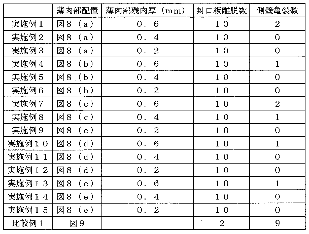
- the comparative example 1 sealed using the sealing body which uses the conventional several member shows that the crack number of a side wall is 9, and it turns out that the number of cracks of a side wall is suppressed notably in an Example.
- the sealing plate 10 when the battery internal pressure rises, the sealing plate 10 is quickly deformed starting from the thin portion 10a having a low strength, and thereby the contact between the gasket 11 and the sealing plate 10 is loosened and a gap capable of discharging gas is generated. Eventually, the sealing plate 10 is completely detached from the outer can 5 in all the batteries (see FIG. 2). As a result, a large opening is quickly formed in the battery, so that even if gas is rapidly generated, the gas exhausting ability can sufficiently follow, and the side wall of the outer can may be damaged after the valve operation (separation of the sealing plate). There is no.
- Comparative Example 1 when the internal pressure of the battery rises, the conductive contact between the pair of explosion-proof valves 23 and 25 is released to cut off the current, and then the crushing groove of the explosion-proof valves 23 and 25 is broken to secure the gas discharge path.
- the present invention is applied to a non-aqueous electrolyte secondary battery.
- the present invention is not limited to this.
- the present invention can be applied to alkaline storage batteries such as nickel-hydrogen storage batteries and nickel-cadmium storage batteries.
- the present invention When the present invention is applied to a non-aqueous electrolyte secondary battery, the following known materials can be used as constituent materials of the battery. Specific examples are shown below.
- the positive electrode plate used in the present invention can be constituted by forming a positive electrode active material layer on a foil-like (thin plate-like) positive electrode current collector.
- a foil-like (thin plate-like) positive electrode current collector aluminum, aluminum alloy, stainless steel, titanium, titanium alloy, or the like can be used. Among them, aluminum or aluminum alloy is preferable because electrochemical elution is unlikely to occur. .
- a lithium-containing transition metal composite oxide for example, a composite oxide containing lithium and at least one metal selected from cobalt, manganese, nickel, chromium, iron, and vanadium
- the general formula Li x Ni y M 1-y O 2 (0.95 ⁇ x ⁇ 1.10, M is at least one of Co, Mn, Cr, Fe, Mg, Ti and Al, 0.6 ⁇ y It is preferable to use a lithium nickel composite oxide represented by ⁇ 0.95).
- the negative electrode plate used in the present invention can be constituted by forming a negative electrode active material layer on a negative electrode current collector.
- a negative electrode current collector copper, copper alloy, nickel, nickel alloy, stainless steel, aluminum, aluminum alloy, etc. can be used. Among them, copper, copper alloy, nickel or nickel alloy can be electrochemically used. It is preferable because typical elution is difficult to occur.
- carbon materials capable of reversibly occluding and releasing lithium ions such as natural graphite, spherical or fibrous artificial graphite, non-graphitizable carbon (hard carbon), graphitizable carbon (soft Carbon) such as carbon), metal oxide materials such as tin oxide and silicon oxide, silicon-containing compounds such as silicon and silicide, and the like can be used.
- a microporous film made of a polyolefin material can be used, and it is preferable to use a combination of a polyolefin material and a heat resistant material.
- the polyolefin include polyethylene, polypropylene, and ethylene-propylene copolymer. These resins can be used alone or in combination of two or more.
- a heat-resistant resin such as aramid, polyimide, or polyamide-imide, or a mixture of a heat-resistant resin and an inorganic filler can be used.
- the nonaqueous electrolyte is prepared by dissolving a lithium salt in a nonaqueous solvent.
- a nonaqueous solvent for example, cyclic carbonates such as ethylene carbonate, propylene carbonate, and butylene carbonate, chain carbonates such as dimethyl carbonate, diethyl carbonate, and ethyl methyl carbonate are used singly or in combination.
- an electron withdrawing strong lithium salt such as LiPF 6, LiBF 4, LiClO 4 is alone, or more mixed and used.
- a known additive such as vinylene carbonate may be added to the non-aqueous electrolyte.
Landscapes
- Chemical & Material Sciences (AREA)
- Chemical Kinetics & Catalysis (AREA)
- Electrochemistry (AREA)
- General Chemical & Material Sciences (AREA)
- Engineering & Computer Science (AREA)
- Manufacturing & Machinery (AREA)
- Inorganic Chemistry (AREA)
- Materials Engineering (AREA)
- Sealing Battery Cases Or Jackets (AREA)
- Gas Exhaust Devices For Batteries (AREA)
- Secondary Cells (AREA)
- Battery Electrode And Active Subsutance (AREA)
Abstract
Description
とができる。ここで、曲線状は、封口板10の外周線と同心円状(図4(a)参照)や同
心円弧状(図4(b)参照)であってもよく、封口板10の外周線と同心円状ではない1
又は複数の曲線状あってもよい(図4(c)、(d)参照)。
本発明を実施するための形態を、本発明をリチウムイオン二次電池に適用した例を用いて、図面を用いて詳細に説明する。図1は、本発明に係る密閉型電池の断面図であり、図2は、本発明に係る密閉型電池の封口部分の内圧上昇による変形を説明する部分拡大断面図である。
<正極の作製>
リチウムニッケルコバルトアルミニウム複合酸化物(LiNi0.8Co0.15Al0.05O2)からなる正極活物質と、アセチレンブラックからなる導電剤と、ポリビニリデンフルオライド(PVDF)からなる結着剤とを、質量比100:2.5:1.7の割合で量り採り、これらをN-メチル-2-ピロリドンからなる有機溶剤と混合し、正極活物質ペーストを調製した。
易黒鉛化炭素粒子からなる負極活物質と、ポリビニリデンフルオライド(PVDF)からなる結着剤とを、カルボキシメチルセルロースからなる増粘剤とを、質量比100:0.6:1の割合で混合し、これらを適量の水と混合し、負極活物質ペーストを調製した。
上記正極と負極とポリエチレン製微多孔膜からなるセパレータ3とを、巻き取り機により捲回し、絶縁性の巻き止めテープを設け、巻回電極群4を完成させた。
厚み0.8mmの円盤状のアルミニウム板をプレス加工して、電池内方となる面に設けられた凹部(深さ0.2mm)からなる薄肉部10a(残肉厚0.6mm)と、電池内方に突出した段差部10bと、が形成された、直径16.59mmの封口板10を作製した。図8は、実施例での封口体の薄肉部配置を示す底面図であり、薄肉部の形状及び配置は、図8(a)に示すとおりである。また、薄肉部10aの長さは1.5mm、幅は0.5mm、断面形状はV字状、封口板外周縁からの距離は2.0mmである。
エチレンカーボネート(EC)と、ジメチルカーボネート(DMC)と、エチルメチルカーボネート(EMC)と、を体積比2:2:6の割合(1気圧、25℃と換算した場合における)で混合した非水溶媒に、電解質塩としてのLiPF6を1.0M(モル/リットル)の割合で溶解したものを非水電解質とした。
上記電極群4の上下にポリプロピレン製の絶縁板6・7を置き、電極群4を外装缶5内に収容し、負極リード9と円筒形外装缶5の缶底とを抵抗溶接した。この後、塑性加工により、外装缶5に幅1.0mm、深さ1.5mmの円周状の溝入れ部5aを形成し、上記非水電解質を円筒形外装缶5内に注液した。この後、封口板10と正極リード8とをレーザ溶接した。外装缶5の開口部を、ガスケット11が挿入された封口板10を用いてカシメ加工して封止し、高さ65mm、直径18mmの実施例1に係る密閉型電池を作製した。なお、円筒形外装缶の材質は、鉄鋼板にニッケルメッキが施されたものであり、その厚みは、缶底面で0.3mm、側壁面で0.25mmである。また、この電池の体積エネルギー密度は、600Wh/Lであった。
表1に示すように、薄肉部の配置、数、残肉厚を変化させたこと以外は、上記実施例1と同様にして、実施例2~15に係る密閉型電池を作製した。なお、実施例2,3の薄肉部10aの長さ、封口体外周縁からの距離は、いずれも実施例1と同様である。また、実施例2~15は、いずれも、溝の幅が0.5mmであり、溝の断面形状はV字状である。
また、実施例4~6の薄肉部10aの長さは1.5mm、封口体外周縁からの距離は2.0mmである。
また、実施例7~9の薄肉部10aは、封口体外周縁からの距離が2.5mmの同心円状である。
また、実施例10~12の薄肉部10aのうち、曲線状のものについては、封口体外周縁からの距離が2.5mmの同心円状であり、直線状のものについては、長さは1.0mm、封口体外周縁からの距離は2.0mmであり、直線状の薄肉部10aの中点で、曲線状の薄肉部と交わっている。
また、実施例13~15の薄肉部10aのうち、曲線状のものについては、封口体外周縁からの距離が2.5mmの同心円弧状であり、中心角は20°であり、直線状のものについては、長さは1.0mm、封口体外周縁からの距離は2.0mmであり、同心円弧状の薄肉部10aの中点で、直線状の薄肉部の外周側端部と交わっている。
図9に示すように、一対の防爆弁23・25を有する従来構造の封口体を用いたこと以外は、上記実施例1と同様にして、比較例1に係る密閉型電池を作製した。一対の防爆弁23・25の破砕溝23a・25aの残肉厚は、破砕溝23aでは0.04mm、破砕溝25aでは0.03mmである。
上記実施例1~15および比較例1に係る密閉型電池をそれぞれ10個用意し、これらの電池を室温(25℃)雰囲気下、定電流1500mAで電圧が4.2Vとなるまで充電した。この後、電池を200℃に設定したホットプレート上において加熱した。この時の封口板又は封口体の外装缶からの離脱の有無及び外装缶側壁の亀裂の発生の有無を目視にて確認し、この結果を下記表1に示す。
た密閉型電池を、溶接による変形を招くことなく実現できることが分かった。
上記では、非水電解質二次電池に本発明を適用した例を用いて説明したが、本発明はこれに限定されるものではない。例えば、ニッケル-水素蓄電池やニッケル-カドミウム蓄電池等のアルカリ蓄電池に本発明を適用することができる。
2 負極板
3 セパレータ
4 捲回電極群
5 外装缶
5a 溝入れ部
6 上部絶縁板
7 下部絶縁板
8 正極リード
9 負極リード
10 封口板
10a 薄肉部
10b 段差部
11 絶縁ガスケット
21 弁キャップ
21a ガス抜き穴
22 PTCサーミスタ
23 防爆弁
23a 破砕溝
24 絶縁板
25 防爆弁
25a 破砕溝
26 端子プレート
26a ガス抜き孔
Claims (7)
- 有底円筒状の外装缶の開口部が、絶縁ガスケットを介して封口板によりカシメ封口された密閉型電池であって、
前記封口板には、電池内圧上昇時に前記封口板の変形の起点となる薄肉部を備え、
電池内圧上昇時には、前記封口板の変形により前記絶縁ガスケットと前記封口板との間に隙間が生じて、前記外装缶内部のガスが前記外装缶外部に排出される、
ことを特徴とする密閉型電池。 - 請求項1に記載の密閉型電池おいて、
前記封口板は、一枚の板状部材により構成される、
ことを特徴とする密閉型電池。 - 請求項1または2に記載の密閉型電池において、
前記封口板は、アルミニウム又はアルミニウム合金からなる、
ことを特徴とする密閉型電池。 - 請求項1、2または3に記載の密閉型電池において、
前記外装缶の側壁には、電池軸方向に突出した溝入れ部が設けられ、
前記薄肉部は、前記溝入れ部よりも内周側に設けられている、
ことを特徴とする密閉型電池。 - 請求項1ないし4のいずれか1項に記載の密閉型電池において、
前記封口板の全体が、前記外装缶の天面よりも低い位置にある、
ことを特徴とする密閉型電池。 - 請求項1ないし5のいずれか1項に記載の密閉型電池において、
電池内圧上昇の進行により、前記封口板は前記外装缶から完全に離脱する、
ことを特徴とする密閉型電池。 - 請求項1ないし6のいずれか1項に記載の密閉型電池において、
前記密閉型電池は、正極板を有するリチウムイオン二次電池であり、
前記正極板は、一般式LixNiyM1-yO2(0.95≦x≦1.10、MはCo、Mn、Cr、Fe、Mg、TiおよびAlの少なくとも1種類、0.6≦y≦0.95)で表されるリチウムニッケル複合酸化物を正極活物質として含み、
前記密閉型電池の体積エネルギー密度が、500Wh/L以上である、
ことを特徴とする密閉型電池。
Priority Applications (3)
| Application Number | Priority Date | Filing Date | Title |
|---|---|---|---|
| CN201480006533.9A CN104956516B (zh) | 2013-01-31 | 2014-01-30 | 密闭型电池 |
| US14/763,405 US20150364735A1 (en) | 2013-01-31 | 2014-01-30 | Sealed battery |
| JP2014559580A JP6250567B2 (ja) | 2013-01-31 | 2014-01-30 | 密閉型電池 |
Applications Claiming Priority (2)
| Application Number | Priority Date | Filing Date | Title |
|---|---|---|---|
| JP2013017321 | 2013-01-31 | ||
| JP2013-017321 | 2013-01-31 |
Publications (1)
| Publication Number | Publication Date |
|---|---|
| WO2014119308A1 true WO2014119308A1 (ja) | 2014-08-07 |
Family
ID=51262023
Family Applications (1)
| Application Number | Title | Priority Date | Filing Date |
|---|---|---|---|
| PCT/JP2014/000471 Ceased WO2014119308A1 (ja) | 2013-01-31 | 2014-01-30 | 密閉型電池 |
Country Status (4)
| Country | Link |
|---|---|
| US (1) | US20150364735A1 (ja) |
| JP (1) | JP6250567B2 (ja) |
| CN (1) | CN104956516B (ja) |
| WO (1) | WO2014119308A1 (ja) |
Cited By (6)
| Publication number | Priority date | Publication date | Assignee | Title |
|---|---|---|---|---|
| WO2015146077A1 (ja) * | 2014-03-28 | 2015-10-01 | 三洋電機株式会社 | 円筒形密閉電池 |
| WO2020129480A1 (ja) * | 2018-12-21 | 2020-06-25 | 三洋電機株式会社 | 密閉電池 |
| WO2020137778A1 (ja) * | 2018-12-28 | 2020-07-02 | 三洋電機株式会社 | 円筒形電池 |
| WO2021182080A1 (ja) * | 2020-03-09 | 2021-09-16 | 三洋電機株式会社 | 密閉電池 |
| JP2022514552A (ja) * | 2019-02-01 | 2022-02-14 | エルジー エナジー ソリューション リミテッド | 二次電池 |
| JP2023537917A (ja) * | 2020-12-24 | 2023-09-06 | エルジー エナジー ソリューション リミテッド | 二次電池およびその製造方法 |
Families Citing this family (28)
| Publication number | Priority date | Publication date | Assignee | Title |
|---|---|---|---|---|
| WO2015146078A1 (ja) | 2014-03-28 | 2015-10-01 | 三洋電機株式会社 | 円筒形密閉電池及び電池パック |
| JP7077940B2 (ja) * | 2016-03-25 | 2022-05-31 | 三洋電機株式会社 | 円筒形電池 |
| KR102635156B1 (ko) * | 2016-04-22 | 2024-02-08 | 삼성에스디아이 주식회사 | 이차 전지 |
| US10707531B1 (en) | 2016-09-27 | 2020-07-07 | New Dominion Enterprises Inc. | All-inorganic solvents for electrolytes |
| US10020477B2 (en) * | 2016-11-01 | 2018-07-10 | Ford Global Technologies, Llc | Battery enclosure vent assembly and venting method |
| JP7031610B2 (ja) * | 2017-01-25 | 2022-03-08 | 三洋電機株式会社 | 二次電池 |
| CN106816573A (zh) * | 2017-03-23 | 2017-06-09 | 惠州亿纬锂能股份有限公司 | 一种电池及电池组件 |
| KR102459627B1 (ko) * | 2017-08-16 | 2022-10-28 | 삼성전자주식회사 | 디설포네이트계 첨가제 및 이를 포함하는 리튬이차전지 |
| US10673038B2 (en) | 2018-03-23 | 2020-06-02 | Chongqing Jinkang New Energy Vehicle Co., Ltd. | Battery cells for battery packs in electric vehicles |
| DE102018220118A1 (de) * | 2018-11-23 | 2020-05-28 | Schott Ag | Durchführung |
| KR102973262B1 (ko) | 2018-11-23 | 2026-06-04 | 쇼오트 아게 | 전기 피드스루 유리-금속 전극 |
| US12272829B2 (en) * | 2018-11-30 | 2025-04-08 | Panasonic Intellectual Property Management Co., Ltd. | Battery |
| JP7432881B2 (ja) * | 2018-12-28 | 2024-02-19 | パナソニックIpマネジメント株式会社 | 電池 |
| CN112271391B (zh) * | 2019-01-09 | 2023-02-10 | 比亚迪股份有限公司 | 动力电池包、储能装置以及电动车 |
| CN109980149B (zh) * | 2019-04-02 | 2024-06-11 | 常州微宙电子科技有限公司 | 用于储能装置的防爆外壳以及储能装置 |
| CN110165120B (zh) * | 2019-05-15 | 2022-04-08 | 广东微电新能源有限公司 | 具有形变泄压功能的电池结构 |
| US12676381B2 (en) * | 2019-12-13 | 2026-07-07 | Panasonic Intellectual Property Management Co., Ltd. | Sealed battery |
| CN114868305B (zh) * | 2019-12-18 | 2025-10-28 | 松下新能源株式会社 | 圆筒形电池 |
| JP7607214B2 (ja) * | 2020-01-31 | 2024-12-27 | パナソニックIpマネジメント株式会社 | 蓄電装置 |
| DE102020107224A1 (de) | 2020-03-17 | 2021-09-23 | Schott Ag | Elektrische Einrichtung |
| CN111740065A (zh) * | 2020-07-15 | 2020-10-02 | 池州市骏智机电科技有限公司 | 一种具有稳定结构的动力电池防爆阀及其加工工艺 |
| CN217239510U (zh) | 2021-01-19 | 2022-08-19 | 株式会社Lg新能源 | 电池、以及电池组和包括电池组的车辆 |
| US12407028B2 (en) | 2021-02-19 | 2025-09-02 | Lg Energy Solution, Ltd. | Electrode assembly, battery, and battery pack and vehicle including the same |
| KR102883214B1 (ko) | 2021-02-19 | 2025-11-07 | 주식회사 엘지에너지솔루션 | 배터리, 그리고 이를 포함하는 배터리 팩 및 자동차 |
| DE102021001258B4 (de) | 2021-03-03 | 2025-01-02 | Kaco Gmbh + Co. Kg | Ventil zum Druckausgleich und/oder zur Notentlüftung eines Behälters, vorzugsweise eines Gehäuses einer Fahrzeugbatterie, sowie Behälter mit einem solchen Ventil |
| EP4318768A4 (en) * | 2021-03-25 | 2025-05-21 | Panasonic Energy Co., Ltd. | SEALED BATTERY |
| DE202021103495U1 (de) | 2021-06-30 | 2022-10-07 | Schott Ag | Elektrische Einrichtung, insbesondere Mikrobatterie |
| JP7401494B2 (ja) | 2021-09-15 | 2023-12-19 | プライムプラネットエナジー&ソリューションズ株式会社 | 二次電池および該二次電池の製造方法 |
Citations (4)
| Publication number | Priority date | Publication date | Assignee | Title |
|---|---|---|---|---|
| JPH0831397A (ja) * | 1994-07-15 | 1996-02-02 | Matsushita Electric Ind Co Ltd | 防爆型電池 |
| JPH11111244A (ja) * | 1997-09-30 | 1999-04-23 | Sanyo Electric Co Ltd | 密閉型蓄電池 |
| JP2002208391A (ja) * | 2001-01-12 | 2002-07-26 | Fdk Corp | アルカリ電池 |
| JP2003109556A (ja) * | 2001-09-27 | 2003-04-11 | Sony Corp | 電 池 |
Family Cites Families (4)
| Publication number | Priority date | Publication date | Assignee | Title |
|---|---|---|---|---|
| JP5011664B2 (ja) * | 2005-07-11 | 2012-08-29 | パナソニック株式会社 | 密閉型二次電池 |
| US8241772B2 (en) * | 2009-06-12 | 2012-08-14 | Tesla Motors, Inc. | Integrated battery pressure relief and terminal isolation system |
| CN201975445U (zh) * | 2011-01-28 | 2011-09-14 | 福建南平南孚电池有限公司 | 一种用于锂-二硫化铁电池的正极端组合体 |
| JP2013114848A (ja) * | 2011-11-28 | 2013-06-10 | Panasonic Corp | リチウムイオン二次電池とその製造方法 |
-
2014
- 2014-01-30 CN CN201480006533.9A patent/CN104956516B/zh active Active
- 2014-01-30 JP JP2014559580A patent/JP6250567B2/ja active Active
- 2014-01-30 WO PCT/JP2014/000471 patent/WO2014119308A1/ja not_active Ceased
- 2014-01-30 US US14/763,405 patent/US20150364735A1/en not_active Abandoned
Patent Citations (4)
| Publication number | Priority date | Publication date | Assignee | Title |
|---|---|---|---|---|
| JPH0831397A (ja) * | 1994-07-15 | 1996-02-02 | Matsushita Electric Ind Co Ltd | 防爆型電池 |
| JPH11111244A (ja) * | 1997-09-30 | 1999-04-23 | Sanyo Electric Co Ltd | 密閉型蓄電池 |
| JP2002208391A (ja) * | 2001-01-12 | 2002-07-26 | Fdk Corp | アルカリ電池 |
| JP2003109556A (ja) * | 2001-09-27 | 2003-04-11 | Sony Corp | 電 池 |
Cited By (21)
| Publication number | Priority date | Publication date | Assignee | Title |
|---|---|---|---|---|
| JPWO2015146077A1 (ja) * | 2014-03-28 | 2017-04-13 | 三洋電機株式会社 | 円筒形密閉電池 |
| US9876206B2 (en) | 2014-03-28 | 2018-01-23 | Sanyo Electric Co., Ltd. | Cylindrical sealed battery |
| WO2015146077A1 (ja) * | 2014-03-28 | 2015-10-01 | 三洋電機株式会社 | 円筒形密閉電池 |
| JPWO2020129480A1 (ja) * | 2018-12-21 | 2021-11-11 | 三洋電機株式会社 | 密閉電池 |
| WO2020129480A1 (ja) * | 2018-12-21 | 2020-06-25 | 三洋電機株式会社 | 密閉電池 |
| JP7531402B2 (ja) | 2018-12-21 | 2024-08-09 | パナソニックエナジー株式会社 | 円筒形電池 |
| US12176567B2 (en) | 2018-12-21 | 2024-12-24 | Panasonic Energy Co., Ltd. | Sealed battery |
| US12424688B2 (en) | 2018-12-28 | 2025-09-23 | Panasonic Energy Co., Ltd. | Cylindrical battery |
| JPWO2020137778A1 (ja) * | 2018-12-28 | 2021-11-18 | 三洋電機株式会社 | 円筒形電池 |
| JP7410882B2 (ja) | 2018-12-28 | 2024-01-10 | パナソニックエナジー株式会社 | 円筒形電池 |
| WO2020137778A1 (ja) * | 2018-12-28 | 2020-07-02 | 三洋電機株式会社 | 円筒形電池 |
| JP2022514552A (ja) * | 2019-02-01 | 2022-02-14 | エルジー エナジー ソリューション リミテッド | 二次電池 |
| JP7615449B2 (ja) | 2019-02-01 | 2025-01-17 | エルジー エナジー ソリューション リミテッド | 二次電池 |
| US12009534B2 (en) | 2019-02-01 | 2024-06-11 | Lg Energy Solution, Ltd. | Secondary battery |
| WO2021182080A1 (ja) * | 2020-03-09 | 2021-09-16 | 三洋電機株式会社 | 密閉電池 |
| CN115176377B (zh) * | 2020-03-09 | 2024-06-11 | 松下新能源株式会社 | 密闭电池 |
| CN115176377A (zh) * | 2020-03-09 | 2022-10-11 | 三洋电机株式会社 | 密闭电池 |
| JP7664220B2 (ja) | 2020-03-09 | 2025-04-17 | パナソニックエナジー株式会社 | 密閉電池 |
| JPWO2021182080A1 (ja) * | 2020-03-09 | 2021-09-16 | ||
| JP2023537917A (ja) * | 2020-12-24 | 2023-09-06 | エルジー エナジー ソリューション リミテッド | 二次電池およびその製造方法 |
| JP7673999B2 (ja) | 2020-12-24 | 2025-05-09 | エルジー エナジー ソリューション リミテッド | 二次電池およびその製造方法 |
Also Published As
| Publication number | Publication date |
|---|---|
| CN104956516A (zh) | 2015-09-30 |
| JP6250567B2 (ja) | 2017-12-20 |
| JPWO2014119308A1 (ja) | 2017-01-26 |
| CN104956516B (zh) | 2017-09-26 |
| US20150364735A1 (en) | 2015-12-17 |
Similar Documents
| Publication | Publication Date | Title |
|---|---|---|
| JP6250567B2 (ja) | 密閉型電池 | |
| JP6254102B2 (ja) | 密閉型電池 | |
| US11824223B2 (en) | Cylindrical sealed battery and battery pack | |
| JP6538650B2 (ja) | 円筒形密閉電池 | |
| CN104126238B (zh) | 封闭式二次电池 | |
| JP6112338B2 (ja) | 二次電池 | |
| JP5538114B2 (ja) | 二次電池 | |
| US20100233524A1 (en) | Cylindrical non-aqueous electrolyte secondary battery | |
| CN102160214A (zh) | 组装封口体及使用该组装封口体的电池 | |
| KR101546545B1 (ko) | 파우치형 리튬이차전지 | |
| JP2009218013A (ja) | 密閉型電池 | |
| CN102047468B (zh) | 圆筒形电池 | |
| JP2009295555A (ja) | 電池 | |
| JP2009302019A (ja) | 密閉型電池 | |
| JP2006040772A (ja) | リチウムイオン電池 | |
| JP2000182588A (ja) | リチウム二次電池 |
Legal Events
| Date | Code | Title | Description |
|---|---|---|---|
| 121 | Ep: the epo has been informed by wipo that ep was designated in this application |
Ref document number: 14745459 Country of ref document: EP Kind code of ref document: A1 |
|
| ENP | Entry into the national phase |
Ref document number: 2014559580 Country of ref document: JP Kind code of ref document: A |
|
| WWE | Wipo information: entry into national phase |
Ref document number: 14763405 Country of ref document: US |
|
| NENP | Non-entry into the national phase |
Ref country code: DE |
|
| 122 | Ep: pct application non-entry in european phase |
Ref document number: 14745459 Country of ref document: EP Kind code of ref document: A1 |