WO2014119308A1 - Batterie étanche - Google Patents
Batterie étanche Download PDFInfo
- Publication number
- WO2014119308A1 WO2014119308A1 PCT/JP2014/000471 JP2014000471W WO2014119308A1 WO 2014119308 A1 WO2014119308 A1 WO 2014119308A1 JP 2014000471 W JP2014000471 W JP 2014000471W WO 2014119308 A1 WO2014119308 A1 WO 2014119308A1
- Authority
- WO
- WIPO (PCT)
- Prior art keywords
- sealing plate
- battery
- sealed battery
- sealed
- plate
- Prior art date
Links
- 238000007789 sealing Methods 0.000 claims abstract description 142
- 229910052782 aluminium Inorganic materials 0.000 claims description 13
- PXHVJJICTQNCMI-UHFFFAOYSA-N nickel Substances [Ni] PXHVJJICTQNCMI-UHFFFAOYSA-N 0.000 claims description 13
- XAGFODPZIPBFFR-UHFFFAOYSA-N aluminium Chemical compound [Al] XAGFODPZIPBFFR-UHFFFAOYSA-N 0.000 claims description 12
- 229910000838 Al alloy Inorganic materials 0.000 claims description 10
- 239000002131 composite material Substances 0.000 claims description 10
- 239000007774 positive electrode material Substances 0.000 claims description 10
- 230000002093 peripheral effect Effects 0.000 claims description 9
- HBBGRARXTFLTSG-UHFFFAOYSA-N Lithium ion Chemical group [Li+] HBBGRARXTFLTSG-UHFFFAOYSA-N 0.000 claims description 8
- 229910001416 lithium ion Inorganic materials 0.000 claims description 8
- RSNHXDVSISOZOB-UHFFFAOYSA-N lithium nickel Chemical compound [Li].[Ni] RSNHXDVSISOZOB-UHFFFAOYSA-N 0.000 claims description 6
- 229910052804 chromium Inorganic materials 0.000 claims description 4
- 229910052742 iron Inorganic materials 0.000 claims description 4
- 229910052719 titanium Inorganic materials 0.000 claims description 4
- 229910052749 magnesium Inorganic materials 0.000 claims description 3
- 229910052748 manganese Inorganic materials 0.000 claims description 3
- 239000007789 gas Substances 0.000 description 37
- 239000000463 material Substances 0.000 description 12
- 239000011255 nonaqueous electrolyte Substances 0.000 description 9
- 239000003792 electrolyte Substances 0.000 description 8
- -1 lithium nickel cobalt aluminum Chemical compound 0.000 description 8
- 230000000052 comparative effect Effects 0.000 description 7
- 230000001788 irregular Effects 0.000 description 6
- 239000007773 negative electrode material Substances 0.000 description 6
- 230000005856 abnormality Effects 0.000 description 5
- 238000005516 engineering process Methods 0.000 description 5
- 238000000034 method Methods 0.000 description 5
- 238000003860 storage Methods 0.000 description 5
- 239000002033 PVDF binder Substances 0.000 description 4
- 230000002411 adverse Effects 0.000 description 4
- 238000007599 discharging Methods 0.000 description 4
- XEEYBQQBJWHFJM-UHFFFAOYSA-N iron Substances [Fe] XEEYBQQBJWHFJM-UHFFFAOYSA-N 0.000 description 4
- 238000004519 manufacturing process Methods 0.000 description 4
- 229910052759 nickel Inorganic materials 0.000 description 4
- 229920002981 polyvinylidene fluoride Polymers 0.000 description 4
- RYGMFSIKBFXOCR-UHFFFAOYSA-N Copper Chemical compound [Cu] RYGMFSIKBFXOCR-UHFFFAOYSA-N 0.000 description 3
- KMTRUDSVKNLOMY-UHFFFAOYSA-N Ethylene carbonate Chemical compound O=C1OCCO1 KMTRUDSVKNLOMY-UHFFFAOYSA-N 0.000 description 3
- 230000008859 change Effects 0.000 description 3
- 239000011651 chromium Substances 0.000 description 3
- 230000007423 decrease Effects 0.000 description 3
- 230000000694 effects Effects 0.000 description 3
- JBTWLSYIZRCDFO-UHFFFAOYSA-N ethyl methyl carbonate Chemical compound CCOC(=O)OC JBTWLSYIZRCDFO-UHFFFAOYSA-N 0.000 description 3
- 230000001771 impaired effect Effects 0.000 description 3
- 229910003002 lithium salt Inorganic materials 0.000 description 3
- 159000000002 lithium salts Chemical class 0.000 description 3
- 239000003960 organic solvent Substances 0.000 description 3
- 229920000098 polyolefin Polymers 0.000 description 3
- 238000002360 preparation method Methods 0.000 description 3
- 239000010936 titanium Substances 0.000 description 3
- 238000003466 welding Methods 0.000 description 3
- OKTJSMMVPCPJKN-UHFFFAOYSA-N Carbon Chemical compound [C] OKTJSMMVPCPJKN-UHFFFAOYSA-N 0.000 description 2
- 229910000881 Cu alloy Inorganic materials 0.000 description 2
- 229910013870 LiPF 6 Inorganic materials 0.000 description 2
- WHXSMMKQMYFTQS-UHFFFAOYSA-N Lithium Chemical compound [Li] WHXSMMKQMYFTQS-UHFFFAOYSA-N 0.000 description 2
- SECXISVLQFMRJM-UHFFFAOYSA-N N-Methylpyrrolidone Chemical compound CN1CCCC1=O SECXISVLQFMRJM-UHFFFAOYSA-N 0.000 description 2
- 229910000990 Ni alloy Inorganic materials 0.000 description 2
- 239000004698 Polyethylene Substances 0.000 description 2
- 239000004743 Polypropylene Substances 0.000 description 2
- 239000011230 binding agent Substances 0.000 description 2
- CKFRRHLHAJZIIN-UHFFFAOYSA-N cobalt lithium Chemical compound [Li].[Co] CKFRRHLHAJZIIN-UHFFFAOYSA-N 0.000 description 2
- 229910052802 copper Inorganic materials 0.000 description 2
- 239000010949 copper Substances 0.000 description 2
- IEJIGPNLZYLLBP-UHFFFAOYSA-N dimethyl carbonate Chemical compound COC(=O)OC IEJIGPNLZYLLBP-UHFFFAOYSA-N 0.000 description 2
- 238000010828 elution Methods 0.000 description 2
- 229910021469 graphitizable carbon Inorganic materials 0.000 description 2
- 229920006015 heat resistant resin Polymers 0.000 description 2
- 239000003779 heat-resistant material Substances 0.000 description 2
- 229910052744 lithium Inorganic materials 0.000 description 2
- 239000011777 magnesium Substances 0.000 description 2
- 239000011572 manganese Substances 0.000 description 2
- 230000007246 mechanism Effects 0.000 description 2
- 229910052751 metal Inorganic materials 0.000 description 2
- 239000002184 metal Substances 0.000 description 2
- 230000004048 modification Effects 0.000 description 2
- 238000012986 modification Methods 0.000 description 2
- 229920000573 polyethylene Polymers 0.000 description 2
- 229920001155 polypropylene Polymers 0.000 description 2
- 238000000926 separation method Methods 0.000 description 2
- 239000002904 solvent Substances 0.000 description 2
- 239000010935 stainless steel Substances 0.000 description 2
- 229910001220 stainless steel Inorganic materials 0.000 description 2
- 229920005992 thermoplastic resin Polymers 0.000 description 2
- 238000004804 winding Methods 0.000 description 2
- ZZXUZKXVROWEIF-UHFFFAOYSA-N 1,2-butylene carbonate Chemical compound CCC1COC(=O)O1 ZZXUZKXVROWEIF-UHFFFAOYSA-N 0.000 description 1
- VAYTZRYEBVHVLE-UHFFFAOYSA-N 1,3-dioxol-2-one Chemical compound O=C1OC=CO1 VAYTZRYEBVHVLE-UHFFFAOYSA-N 0.000 description 1
- 241000270728 Alligator Species 0.000 description 1
- 229920002134 Carboxymethyl cellulose Polymers 0.000 description 1
- VYZAMTAEIAYCRO-UHFFFAOYSA-N Chromium Chemical compound [Cr] VYZAMTAEIAYCRO-UHFFFAOYSA-N 0.000 description 1
- 229910000570 Cupronickel Inorganic materials 0.000 description 1
- OIFBSDVPJOWBCH-UHFFFAOYSA-N Diethyl carbonate Chemical compound CCOC(=O)OCC OIFBSDVPJOWBCH-UHFFFAOYSA-N 0.000 description 1
- 229910013063 LiBF 4 Inorganic materials 0.000 description 1
- 229910013684 LiClO 4 Inorganic materials 0.000 description 1
- 229910012851 LiCoO 2 Inorganic materials 0.000 description 1
- 229910002995 LiNi0.8Co0.15Al0.05O2 Inorganic materials 0.000 description 1
- 239000004962 Polyamide-imide Substances 0.000 description 1
- 239000004642 Polyimide Substances 0.000 description 1
- VYPSYNLAJGMNEJ-UHFFFAOYSA-N Silicium dioxide Chemical compound O=[Si]=O VYPSYNLAJGMNEJ-UHFFFAOYSA-N 0.000 description 1
- XUIMIQQOPSSXEZ-UHFFFAOYSA-N Silicon Chemical compound [Si] XUIMIQQOPSSXEZ-UHFFFAOYSA-N 0.000 description 1
- 229910000831 Steel Inorganic materials 0.000 description 1
- 229910001069 Ti alloy Inorganic materials 0.000 description 1
- RTAQQCXQSZGOHL-UHFFFAOYSA-N Titanium Chemical compound [Ti] RTAQQCXQSZGOHL-UHFFFAOYSA-N 0.000 description 1
- 230000002159 abnormal effect Effects 0.000 description 1
- 239000006230 acetylene black Substances 0.000 description 1
- 239000000654 additive Substances 0.000 description 1
- 230000000996 additive effect Effects 0.000 description 1
- 239000003125 aqueous solvent Substances 0.000 description 1
- 239000004760 aramid Substances 0.000 description 1
- 229920003235 aromatic polyamide Polymers 0.000 description 1
- 229910021383 artificial graphite Inorganic materials 0.000 description 1
- OJIJEKBXJYRIBZ-UHFFFAOYSA-N cadmium nickel Chemical compound [Ni].[Cd] OJIJEKBXJYRIBZ-UHFFFAOYSA-N 0.000 description 1
- 229910052799 carbon Inorganic materials 0.000 description 1
- 239000003575 carbonaceous material Substances 0.000 description 1
- 239000001768 carboxy methyl cellulose Substances 0.000 description 1
- 235000010948 carboxy methyl cellulose Nutrition 0.000 description 1
- 239000008112 carboxymethyl-cellulose Substances 0.000 description 1
- 150000005678 chain carbonates Chemical class 0.000 description 1
- 229910017052 cobalt Inorganic materials 0.000 description 1
- 239000010941 cobalt Substances 0.000 description 1
- GUTLYIVDDKVIGB-UHFFFAOYSA-N cobalt atom Chemical compound [Co] GUTLYIVDDKVIGB-UHFFFAOYSA-N 0.000 description 1
- 239000006258 conductive agent Substances 0.000 description 1
- 239000000470 constituent Substances 0.000 description 1
- 229920001577 copolymer Polymers 0.000 description 1
- 239000011889 copper foil Substances 0.000 description 1
- 150000005676 cyclic carbonates Chemical class 0.000 description 1
- 238000010586 diagram Methods 0.000 description 1
- 239000008151 electrolyte solution Substances 0.000 description 1
- 239000011888 foil Substances 0.000 description 1
- 229910021385 hard carbon Inorganic materials 0.000 description 1
- 229910052739 hydrogen Inorganic materials 0.000 description 1
- 239000001257 hydrogen Substances 0.000 description 1
- 230000006872 improvement Effects 0.000 description 1
- 239000011256 inorganic filler Substances 0.000 description 1
- 229910003475 inorganic filler Inorganic materials 0.000 description 1
- 238000009413 insulation Methods 0.000 description 1
- WPBNNNQJVZRUHP-UHFFFAOYSA-L manganese(2+);methyl n-[[2-(methoxycarbonylcarbamothioylamino)phenyl]carbamothioyl]carbamate;n-[2-(sulfidocarbothioylamino)ethyl]carbamodithioate Chemical compound [Mn+2].[S-]C(=S)NCCNC([S-])=S.COC(=O)NC(=S)NC1=CC=CC=C1NC(=S)NC(=O)OC WPBNNNQJVZRUHP-UHFFFAOYSA-L 0.000 description 1
- 239000002905 metal composite material Substances 0.000 description 1
- 229910044991 metal oxide Inorganic materials 0.000 description 1
- 150000004706 metal oxides Chemical class 0.000 description 1
- 239000000203 mixture Substances 0.000 description 1
- 229910021382 natural graphite Inorganic materials 0.000 description 1
- 229910021470 non-graphitizable carbon Inorganic materials 0.000 description 1
- 239000002245 particle Substances 0.000 description 1
- 239000004033 plastic Substances 0.000 description 1
- 229920003023 plastic Polymers 0.000 description 1
- 238000007747 plating Methods 0.000 description 1
- 229920002312 polyamide-imide Polymers 0.000 description 1
- 229920001721 polyimide Polymers 0.000 description 1
- 238000003825 pressing Methods 0.000 description 1
- 230000001737 promoting effect Effects 0.000 description 1
- RUOJZAUFBMNUDX-UHFFFAOYSA-N propylene carbonate Chemical compound CC1COC(=O)O1 RUOJZAUFBMNUDX-UHFFFAOYSA-N 0.000 description 1
- 229920005989 resin Polymers 0.000 description 1
- 239000011347 resin Substances 0.000 description 1
- 238000011076 safety test Methods 0.000 description 1
- 150000003839 salts Chemical class 0.000 description 1
- 229910021332 silicide Inorganic materials 0.000 description 1
- FVBUAEGBCNSCDD-UHFFFAOYSA-N silicide(4-) Chemical compound [Si-4] FVBUAEGBCNSCDD-UHFFFAOYSA-N 0.000 description 1
- 229910052710 silicon Inorganic materials 0.000 description 1
- 239000010703 silicon Substances 0.000 description 1
- 229910052814 silicon oxide Inorganic materials 0.000 description 1
- 239000002210 silicon-based material Substances 0.000 description 1
- 229910021384 soft carbon Inorganic materials 0.000 description 1
- 239000010959 steel Substances 0.000 description 1
- 239000002562 thickening agent Substances 0.000 description 1
- XOLBLPGZBRYERU-UHFFFAOYSA-N tin dioxide Chemical compound O=[Sn]=O XOLBLPGZBRYERU-UHFFFAOYSA-N 0.000 description 1
- 229910001887 tin oxide Inorganic materials 0.000 description 1
- 229910052723 transition metal Inorganic materials 0.000 description 1
- 150000003624 transition metals Chemical class 0.000 description 1
- 229910052720 vanadium Inorganic materials 0.000 description 1
- GPPXJZIENCGNKB-UHFFFAOYSA-N vanadium Chemical compound [V]#[V] GPPXJZIENCGNKB-UHFFFAOYSA-N 0.000 description 1
- XLYOFNOQVPJJNP-UHFFFAOYSA-N water Substances O XLYOFNOQVPJJNP-UHFFFAOYSA-N 0.000 description 1
Images


Classifications
-
- H—ELECTRICITY
- H01—ELECTRIC ELEMENTS
- H01M—PROCESSES OR MEANS, e.g. BATTERIES, FOR THE DIRECT CONVERSION OF CHEMICAL ENERGY INTO ELECTRICAL ENERGY
- H01M4/00—Electrodes
- H01M4/02—Electrodes composed of, or comprising, active material
- H01M4/36—Selection of substances as active materials, active masses, active liquids
- H01M4/48—Selection of substances as active materials, active masses, active liquids of inorganic oxides or hydroxides
- H01M4/52—Selection of substances as active materials, active masses, active liquids of inorganic oxides or hydroxides of nickel, cobalt or iron
- H01M4/525—Selection of substances as active materials, active masses, active liquids of inorganic oxides or hydroxides of nickel, cobalt or iron of mixed oxides or hydroxides containing iron, cobalt or nickel for inserting or intercalating light metals, e.g. LiNiO2, LiCoO2 or LiCoOxFy
-
- H—ELECTRICITY
- H01—ELECTRIC ELEMENTS
- H01M—PROCESSES OR MEANS, e.g. BATTERIES, FOR THE DIRECT CONVERSION OF CHEMICAL ENERGY INTO ELECTRICAL ENERGY
- H01M10/00—Secondary cells; Manufacture thereof
- H01M10/05—Accumulators with non-aqueous electrolyte
- H01M10/052—Li-accumulators
-
- H—ELECTRICITY
- H01—ELECTRIC ELEMENTS
- H01M—PROCESSES OR MEANS, e.g. BATTERIES, FOR THE DIRECT CONVERSION OF CHEMICAL ENERGY INTO ELECTRICAL ENERGY
- H01M10/00—Secondary cells; Manufacture thereof
- H01M10/05—Accumulators with non-aqueous electrolyte
- H01M10/052—Li-accumulators
- H01M10/0525—Rocking-chair batteries, i.e. batteries with lithium insertion or intercalation in both electrodes; Lithium-ion batteries
-
- H—ELECTRICITY
- H01—ELECTRIC ELEMENTS
- H01M—PROCESSES OR MEANS, e.g. BATTERIES, FOR THE DIRECT CONVERSION OF CHEMICAL ENERGY INTO ELECTRICAL ENERGY
- H01M10/00—Secondary cells; Manufacture thereof
- H01M10/05—Accumulators with non-aqueous electrolyte
- H01M10/058—Construction or manufacture
- H01M10/0587—Construction or manufacture of accumulators having only wound construction elements, i.e. wound positive electrodes, wound negative electrodes and wound separators
-
- H—ELECTRICITY
- H01—ELECTRIC ELEMENTS
- H01M—PROCESSES OR MEANS, e.g. BATTERIES, FOR THE DIRECT CONVERSION OF CHEMICAL ENERGY INTO ELECTRICAL ENERGY
- H01M50/00—Constructional details or processes of manufacture of the non-active parts of electrochemical cells other than fuel cells, e.g. hybrid cells
- H01M50/10—Primary casings; Jackets or wrappings
- H01M50/147—Lids or covers
- H01M50/166—Lids or covers characterised by the methods of assembling casings with lids
- H01M50/167—Lids or covers characterised by the methods of assembling casings with lids by crimping
-
- H—ELECTRICITY
- H01—ELECTRIC ELEMENTS
- H01M—PROCESSES OR MEANS, e.g. BATTERIES, FOR THE DIRECT CONVERSION OF CHEMICAL ENERGY INTO ELECTRICAL ENERGY
- H01M50/00—Constructional details or processes of manufacture of the non-active parts of electrochemical cells other than fuel cells, e.g. hybrid cells
- H01M50/10—Primary casings; Jackets or wrappings
- H01M50/147—Lids or covers
- H01M50/166—Lids or covers characterised by the methods of assembling casings with lids
- H01M50/171—Lids or covers characterised by the methods of assembling casings with lids using adhesives or sealing agents
-
- H—ELECTRICITY
- H01—ELECTRIC ELEMENTS
- H01M—PROCESSES OR MEANS, e.g. BATTERIES, FOR THE DIRECT CONVERSION OF CHEMICAL ENERGY INTO ELECTRICAL ENERGY
- H01M50/00—Constructional details or processes of manufacture of the non-active parts of electrochemical cells other than fuel cells, e.g. hybrid cells
- H01M50/30—Arrangements for facilitating escape of gases
- H01M50/317—Re-sealable arrangements
- H01M50/325—Re-sealable arrangements comprising deformable valve members, e.g. elastic or flexible valve members
-
- H—ELECTRICITY
- H01—ELECTRIC ELEMENTS
- H01M—PROCESSES OR MEANS, e.g. BATTERIES, FOR THE DIRECT CONVERSION OF CHEMICAL ENERGY INTO ELECTRICAL ENERGY
- H01M50/00—Constructional details or processes of manufacture of the non-active parts of electrochemical cells other than fuel cells, e.g. hybrid cells
- H01M50/30—Arrangements for facilitating escape of gases
- H01M50/342—Non-re-sealable arrangements
- H01M50/3425—Non-re-sealable arrangements in the form of rupturable membranes or weakened parts, e.g. pierced with the aid of a sharp member
-
- H—ELECTRICITY
- H01—ELECTRIC ELEMENTS
- H01M—PROCESSES OR MEANS, e.g. BATTERIES, FOR THE DIRECT CONVERSION OF CHEMICAL ENERGY INTO ELECTRICAL ENERGY
- H01M50/00—Constructional details or processes of manufacture of the non-active parts of electrochemical cells other than fuel cells, e.g. hybrid cells
- H01M50/50—Current conducting connections for cells or batteries
- H01M50/572—Means for preventing undesired use or discharge
- H01M50/574—Devices or arrangements for the interruption of current
- H01M50/578—Devices or arrangements for the interruption of current in response to pressure
-
- H—ELECTRICITY
- H01—ELECTRIC ELEMENTS
- H01M—PROCESSES OR MEANS, e.g. BATTERIES, FOR THE DIRECT CONVERSION OF CHEMICAL ENERGY INTO ELECTRICAL ENERGY
- H01M2200/00—Safety devices for primary or secondary batteries
- H01M2200/20—Pressure-sensitive devices
-
- H—ELECTRICITY
- H01—ELECTRIC ELEMENTS
- H01M—PROCESSES OR MEANS, e.g. BATTERIES, FOR THE DIRECT CONVERSION OF CHEMICAL ENERGY INTO ELECTRICAL ENERGY
- H01M50/00—Constructional details or processes of manufacture of the non-active parts of electrochemical cells other than fuel cells, e.g. hybrid cells
- H01M50/10—Primary casings; Jackets or wrappings
- H01M50/147—Lids or covers
-
- Y—GENERAL TAGGING OF NEW TECHNOLOGICAL DEVELOPMENTS; GENERAL TAGGING OF CROSS-SECTIONAL TECHNOLOGIES SPANNING OVER SEVERAL SECTIONS OF THE IPC; TECHNICAL SUBJECTS COVERED BY FORMER USPC CROSS-REFERENCE ART COLLECTIONS [XRACs] AND DIGESTS
- Y02—TECHNOLOGIES OR APPLICATIONS FOR MITIGATION OR ADAPTATION AGAINST CLIMATE CHANGE
- Y02E—REDUCTION OF GREENHOUSE GAS [GHG] EMISSIONS, RELATED TO ENERGY GENERATION, TRANSMISSION OR DISTRIBUTION
- Y02E60/00—Enabling technologies; Technologies with a potential or indirect contribution to GHG emissions mitigation
- Y02E60/10—Energy storage using batteries
-
- Y—GENERAL TAGGING OF NEW TECHNOLOGICAL DEVELOPMENTS; GENERAL TAGGING OF CROSS-SECTIONAL TECHNOLOGIES SPANNING OVER SEVERAL SECTIONS OF THE IPC; TECHNICAL SUBJECTS COVERED BY FORMER USPC CROSS-REFERENCE ART COLLECTIONS [XRACs] AND DIGESTS
- Y02—TECHNOLOGIES OR APPLICATIONS FOR MITIGATION OR ADAPTATION AGAINST CLIMATE CHANGE
- Y02P—CLIMATE CHANGE MITIGATION TECHNOLOGIES IN THE PRODUCTION OR PROCESSING OF GOODS
- Y02P70/00—Climate change mitigation technologies in the production process for final industrial or consumer products
- Y02P70/50—Manufacturing or production processes characterised by the final manufactured product
Definitions
- the present invention relates to a sealed battery, and more particularly to a sealed battery having a gas discharge function.
- lithium ion secondary batteries Since lithium ion secondary batteries have high energy density and high capacity, they are widely used as driving power sources for mobile information terminals such as mobile phones and notebook computers. Recently, lithium ion secondary batteries are expected to be used in applications requiring high voltage and high capacity, such as drive power sources for battery-powered automobiles and household power storage systems.
- FIG. 9 is a cross-sectional view showing a sealing member having a conventional structure.
- the sealing body of the sealed battery includes a pair of explosion-proof valves each provided with a valve cap 21 provided with a vent hole 21a, a PTC thermistor 22, and crushing grooves 23a and 25a that crush when the battery internal pressure rises. 23, 25, an insulating plate 24 that prevents electrical conduction between the outer peripheral portions of the pair of explosion-proof valves 23, 25, and a terminal plate 26 that is provided with a gas vent hole 26a and is electrically connected to the positive electrode plate. I have. In this technique, when the battery internal pressure rises, first, the electrical contact between the pair of explosion-proof valves 23 and 25 is cut, and the energization to the valve cap 21 is cut off.
- Patent Documents 1 to 3 technologies relating to the improvement of battery safety.
- Patent Document 1 the release portion formed by the scratch on the battery terminal is ruptured when the internal battery pressure exceeds a predetermined battery operating range, the breakable electrical connector is broken, and the connector plate and the battery terminal Discloses a technology relating to a battery interconnection stem that disconnects the electrical connection between the two. According to this technology, a system for integrating the battery release characteristics with means for simultaneously disconnecting cells from the battery pack and thereby isolating the cells can be realized.
- Patent Document 2 discloses a technique in which a sealing plate is formed with an annular groove divided by a connecting portion, and the connecting portions are provided in at least two places. According to this technology, when the internal pressure of the battery is abnormally increased, a break in the groove is surely generated, but with a small impact, a non-aqueous secondary battery that does not inadvertently break in the groove can be realized. .
- Patent Document 3 discloses a self-recovering first safety valve that can be repeatedly opened and closed, a slit formed in an annular shape leaving a hinge portion, and a thermoplastic resin that hermetically closes the slit. And a safety valve comprising a second safety valve that is configured such that the opening pressure of the second safety valve is set higher than the first safety valve and lower than the pressure at which the sealing portion of the battery case is damaged, and The second safety valve discloses that the thermoplastic resin is broken and the portion surrounded by the slit is bent at the hinge portion to open. According to this technique, the first safety valve that self-recovers can be reused even after the battery internal pressure rises, and further, the battery case can be effectively prevented from rupture with the second safety valve that does not self-reset.
- This invention solves the said subject, and aims at providing the sealed battery which can discharge
- the present invention for solving the above problems is a sealed battery in which the opening of a bottomed cylindrical outer can is caulked and sealed with a sealing plate via an insulating gasket, and the sealing plate includes a battery internal pressure.
- a thin-walled portion that serves as a starting point for deformation of the sealing plate when raised, and when the internal pressure of the battery rises, a gap is generated between the insulating gasket and the sealing plate due to deformation of the sealing plate, and the gas inside the outer can It is discharged outside the outer can.
- FIG. 1 is a cross-sectional view of a sealed battery according to the present invention
- FIG. 2 is a diagram for explaining deformation due to an increase in internal pressure of a sealing portion of the sealed battery according to the present invention.
- the sealing plate 10 of the sealed battery according to the present invention is provided with a thin-walled portion 10a that is thinner than other portions, thereby reducing the strength of the portion. ing. For this reason, when the battery internal pressure rises, the sealing plate 10 is deformed starting from the thin portion 10a (see FIGS. 2A and 2B). Then, when the deformation of the sealing plate 10 proceeds, the contact between the insulating gasket 11 and the sealing plate 10 is loosened, and a gap capable of discharging gas is generated between the sealing plate 10 and the insulating gasket 11 (FIG. 2 (c), ( d)).
- the gas exhaust capability can sufficiently follow. Therefore, there is no possibility that damage due to internal pressure is applied to the side wall of the outer can 5 after the opening is formed, and cracks on the side wall of the outer can 5 can be remarkably suppressed. Thereby, the discharge direction of the gas inside the outer can 5 or the electrolyte can be guided only to the sealing plate 10 side. For this reason, it is prevented that the member adjacent to the side wall direction of the outer can 10 is adversely affected.
- the sealed battery according to the present invention is used for an assembled battery, even if an abnormality occurs in one unit cell, It is prevented that the safety of other cells constituting the assembled battery is impaired.
- the sealing plate is formed of a single plate-like member.
- the sealing plate 10 is a single plate-like member, the sealing plate 10 can be easily deformed when the internal pressure is increased, the separation from the insulating gasket 11 can be accelerated, and the manufacturing of the sealing plate 10 is simplified.
- the single plate-like member may be substantially constituted by a single plate, for example, a single clad material in which a plurality of materials are bonded and integrated. Also good. Further, the plate-like member may have a constant thickness, may have a change in thickness, or may be formed with one or more stepped portions 10b for the purpose of increasing the strength. Moreover, the structure etc. to which the member used as the contact of a connection with the element outside a battery is partially added may be sufficient.
- the sealing plate can be made of aluminum or an aluminum alloy.
- Aluminum or aluminum alloy is suitable as a material for the sealing plate because it is lightweight, easily deformed, and has high resistance to an electrolytic solution.
- the said structure WHEREIN The grooved part which protruded in the battery axial direction is provided in the side wall of the said exterior can,
- the said thin part can be set as the structure provided in the inner peripheral side rather than the said grooved part.
- a groove portion 5a protruding in the battery axial direction is often provided on the side wall of the outer can 5; however, the pressure inside the battery is almost not in the sealing plate portion outside the groove portion 5a. Since it does not act, when the thin part 10a is provided in this part, there exists a possibility that the effect of this invention may become small. For this reason, when forming the grooving part 5a, it is preferable that the thin part 10a is provided including the sealing plate part inside the grooving part 5a, and only in the sealing plate part inside the grooving part 5a. More preferably.
- the entire sealing plate 10 is in a position lower than the top surface of the outer can 5.
- space efficiency can be enhanced and direct impact can be suppressed from acting on the sealing plate 10. Can be suppressed.
- the said structure is achieved by providing the convex level
- this invention is not limited to this structure.
- the sealing plate 10 may have a flat configuration without a step, and may include a convex step portion outside the battery.
- step-difference part convex in the same direction or convex in a different direction may be sufficient.
- the sealing plate can be completely detached from the outer can as the battery internal pressure increases.
- This configuration is preferable because the opening area for discharging gas can be greatly increased.
- the sealed battery is a lithium ion secondary battery having a positive electrode plate, and the positive electrode plate has a general formula Li x Ni y M 1-y O 2 (0.95 ⁇ x ⁇ 1.10.
- M includes at least one of Co, Mn, Cr, Fe, Mg, Ti and Al, and a lithium nickel composite oxide represented by 0.6 ⁇ y ⁇ 0.95) as a positive electrode active material, and the sealed battery
- the volume energy density may be 500 Wh / L or more.
- the lithium nickel composite oxide has a larger capacity, higher energy density, and lower cost than the lithium cobalt composite oxide (LiCoO 2 ) that has been used as a positive electrode active material for lithium ion secondary batteries.
- a battery having a high energy density with a volume energy density of 500 Wh / L or more can be obtained at low cost.
- the mass of the lithium nickel composite oxide is preferably 50% by mass or more of the total mass of the positive electrode active material, more preferably 80% by mass or more, and further preferably 100% by mass.
- the number of the thin-walled portions 10a may be one as shown in FIGS. 3 to 5, or may be two or more.
- the planar shape of the thin portion is not particularly limited, and may be, for example, a linear shape such as a straight line or a curved shape, or a planar shape such as a polygon, a circle, or any other irregular shape. Or a combination thereof.
- positioning may be regular (equal intervals with the same size), random arrangement
- the thin-walled portion 10 a can be configured to have one or a plurality of straight lines.
- the straight line may be a straight line along the diameter of the sealing plate 10 as shown in FIG. 3A, or a straight line that does not follow the diameter of the sealing plate 10 as shown in FIG. It may be a shape.
- the sealing plate 10 may be arranged evenly (at equal intervals), as shown in FIG. 3 (d). In this way, the configuration may be unevenly (randomly) arranged.
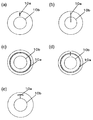
- the thin part 10a can be set as the structure which is 1 or several curve shape.
- the curved shape may be concentric with the outer peripheral line of the sealing plate 10 (see FIG. 4A) or concentric arc shape (see FIG. 4B), and concentric with the outer peripheral line of the sealing plate 10.
- there may be a plurality of curved shapes see FIGS. 4C and 4D).
- the thin portion 10a can be configured to be planar.
- the planar shape is not particularly limited, and may be a polygon (see FIG. 5A), a circle, an ellipse, a sector, or any other irregular shape (see FIG. 5B).
- the thin portion may be a combination of a linear shape, a curved shape, and a planar shape.
- the some thin part 10a may be the structure which a part overlaps (refer FIG.5 (c)), and the structure (refer FIG.5 (d)) which does not overlap may be sufficient.
- the cross-sectional shape of the thin portion is not particularly limited.
- the cross-sectional shape may be a V-shaped (triangular) shape, a quadrangular shape, a U-shape, a semicircular shape, etc., and the groove depth is constant. Or may change.
- the structure provided with the flat surface parallel to a sealing board surface may be sufficient, and the structure provided with the uneven surface which has regular unevenness
- corrugation may be sufficient.
- the corner portion of the concave portion is configured to have an obtuse angle or R
- the thin portion is configured to be a concave portion formed on the inner surface of the battery, or the remaining thickness of the thin portion It is preferable to make the thickness difficult to break.
- the thin portion 10a may be formed by providing a recess in the inside surface of the battery of the sealing plate 10, but FIG. 6 (a).
- the sealing plate 10 may be formed by providing a recess on the outer surface of the battery.
- the sealing plate 10 may be formed by providing recesses on both sides.
- the thin-walled portion 10a is indicated by a broken line when a concave portion is provided on the outer side of the battery.
- the concave portions formed on both surfaces may be aligned when the sealing plate 10 is seen through the plane (see FIG. 7 (d)).
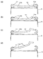
- the concave portions formed may be arranged so as not to overlap (see FIG. 6C and FIG. 7C), or may be arranged so that a part of the concave portions formed on both surfaces are overlapped (FIG. 6 ( d)).
- the arrangement of the thin portion 10a is not particularly limited.
- the portion caulked by the insulating gasket 11 is not deformed when the internal pressure is increased. Therefore, if a thin wall portion is provided in this portion, the sealing plate is a starting point for deformation of the sealing plate when the battery internal pressure is increased in the present invention.
- the sealing plate is a starting point for deformation of the sealing plate when the battery internal pressure is increased in the present invention.
- the sealing reliability may be impaired. Therefore, it is preferable that there is no thin portion in the caulked portion of the sealing plate 10.
- step-difference part 10b in the sealing board 10 it is preferable that at least one part of the thin part 10a exists in an outer side part from the level
- the method for forming the thin-walled portion is not particularly limited, but it is preferable because it is easy to form by pressing.
- the sealing plate also has a configuration that also serves as one of the external terminals of the positive and negative electrodes of the battery.
- the battery structure can be simplified.
- the outer can is preferably configured to serve as the other external terminal.
- a sealed battery that can discharge gas only from the sealing plate side can be realized.
- This sealed battery does not adversely affect the member where the side wall of the outer can is arranged on the alligator, and does not hinder the safety of other batteries when applied to, for example, an assembled battery.
- FIG. 1 is a cross-sectional view of a sealed battery according to the present invention.
- FIG. 2 is a partially enlarged cross-sectional view for explaining deformation due to an increase in internal pressure of the sealing portion of the sealed battery according to the present invention.
- FIG. 3 is a bottom view showing an example of arrangement of the thin portion of the sealing plate.
- FIG. 4 is a bottom view showing a modified example of the arrangement of the thin portion of the sealing plate.
- FIG. 5 is a bottom view showing a further modification of the arrangement of the thin portion of the sealing plate.
- FIG. 6 is a bottom perspective view of the arrangement of the thin portion when a thin portion is provided on at least the outside of the battery on the sealing plate.
- FIG. 7 is a cross-sectional view showing a modified example of the arrangement of the thin portion of the sealing plate.
- FIG. 8 is a bottom view showing the arrangement of the thin portion of the sealing plate in the embodiment.
- FIG. 8 (a) shows Embodiments 1 to 3
- FIG. 8 (b) shows Embodiments 4 to 6, and
- FIG. 8 (c) Shows Examples 7 to 9,
- FIG. 8D shows Examples 10 to 12, and
- FIG. 8E shows Examples 13 to 15, respectively.
- FIG. 1 is a cross-sectional view of a sealed battery according to the present invention
- FIG. 2 is a partially enlarged cross-sectional view for explaining deformation due to an increase in internal pressure of a sealing portion of the sealed battery according to the present invention.
- the nonaqueous electrolyte secondary battery includes a wound electrode group 4 in which a positive electrode plate 1 and a negative electrode plate 2 are wound in a spiral shape with a separator 3 interposed therebetween.
- the wound electrode group 4 has insulating plates 6 and 7 arranged on the upper and lower sides, respectively, and is housed inside a bottomed cylindrical metal outer can 5.
- a non-aqueous electrolyte (not shown) is injected inside the outer can 5, and the opening of the outer can 5 is sealed by caulking with a sealing plate 10 via a gasket 11. .
- the lead 9 of the negative electrode plate 2 is welded to the inner bottom portion of the outer can 5, and the lead 8 of the positive electrode plate 1 is welded to the lower surface of the sealing plate 10.
- the outer can 5 functions as a negative electrode external terminal
- the sealing plate 10 functions as a positive electrode external terminal.
- the periphery of the upper insulating plate 6 is held by a grooving portion 5a formed on the side wall of the outer can 5, and the wound electrode group 4 is fixed from above.
- the sealing plate 10 is provided with a thin portion 10a having a thinner plate thickness than the other portions, thereby reducing the strength of the thin portion 10a. For this reason, when the battery internal pressure rises, the sealing plate 10 is deformed starting from the thin portion 10a (see FIGS. 2A and 2B). Then, when the deformation of the sealing plate 10 proceeds, the caulking seal between the insulating gasket 11 and the sealing plate 10 is loosened, and a gap capable of discharging gas is generated between the sealing plate 10 and the insulating gasket 11 (FIG. 2 (c), (See (d)). When the battery internal pressure further increases, the sealing plate 10 is detached from the outer can 5.
- the gas exhaust capability can sufficiently follow even if gas is rapidly generated, and there is no risk of damage caused by internal pressure on the side wall of the outer can 5 after the opening is formed, Generation of cracks on the side wall of the outer can 5 can be suppressed.
- the discharge direction of the gas inside the outer can and the electrolyte can be guided only to the sealing plate side. For this reason, it is prevented that the member adjacent to the outer can side wall direction is adversely affected.
- the sealed battery according to the present invention is used for an assembled battery, even if an abnormality occurs in one unit cell, the assembled battery It is prevented that the safety of other batteries constituting the battery is impaired.
- the sealing plate 10 is preferably composed of a single plate-like member made of aluminum or an aluminum alloy.
- the sealing plate is easily deformed when the battery internal pressure is increased, and the manufacturing of the sealing plate 10 is simplified.
- Aluminum or aluminum alloy is suitable as a material for the sealing plate 10 because it is lightweight, easily deformed, and has high resistance to the electrolyte.
- the other member may be attached to the sealing board.
- a groove portion 5a protruding in the battery axial direction is provided on the side wall of the outer can 5.
- the insulating gasket 11 is distribute
- the thin part 10a of the sealing board 10 is provided in the inner peripheral side rather than the grooving part 5a. This is because the deformation promoting effect is small even if the thin portion 10a is provided in the sealing plate 10 portion outside the grooving portion 5a.
- the entire sealing plate 10 is in a position lower than the top surface of the outer can 5.
- the sealing plate 10 may have a flat configuration without a step, or may have a stepped portion 10b as shown in FIG.
- the direction of the step may be convex inward of the battery as shown in FIG. 1 or may be convex outward of the battery, and may be convex in the same direction or in different directions.
- step-difference part of these may be sufficient.
- strength of the sealing board 10 can be raised by providing the level
- the number of the thin portions may be one as shown in FIGS. 3 to 5, or may be two or more.
- the planar shape of the thin portion is not particularly limited, and may be, for example, a linear shape such as a straight line or a curved shape, or a planar shape such as a polygon, a circle, or any other irregular shape. Or a combination thereof.
- positioning may be regular (equal intervals with the same size), random arrangement
- FIGS. 3 to 5 are bottom views showing examples of arrangement of thin portions of the sealing plate, respectively, and FIG. 6 is a bottom perspective view of the arrangement of thin portions when the thin portion is provided on at least the battery inner surface of the sealing plate.
- FIG. 7 is a cross-sectional view showing a modification of the arrangement of the thin portion of the sealing plate.
- the thin part 10a can be configured to have one or a plurality of straight lines.
- the straight line may be a straight line along the diameter of the sealing plate 10 as shown in FIG. 3A, or a straight line that does not follow the diameter of the sealing plate 10 as shown in FIG. It may be a shape.
- FIG. 3 (c) a configuration in which they are evenly arranged on the sealing plate 10 may be used, and as shown in FIG. The arrangement may be sufficient.
- the thin part 10a can be made into the structure which is 1 or several curve shape, for example, as shown in FIG.
- the curved shape may be concentric with the outer peripheral line of the sealing plate 10 as shown in FIGS. 4A and 4B, or concentric arc shape, as shown in FIGS. 4C and 4D.
- the thin part 10a can be made into the structure which is planar as shown, for example in FIG.
- the planar shape is not particularly limited, and may be a polygon (see FIG. 5A), a circle, an ellipse, a sector, or any other irregular shape (see FIG. 5B).
- FIGS. 5C and 5D a combination of a linear shape, a curved shape, and a planar shape may be used.
- the some thin part 10a may be the structure which overlaps (refer FIG.5 (c)), and the structure (refer FIG.5 (d)) which does not overlap may be sufficient.
- the thin portion 10a may be formed by providing a recess in the inside surface of the battery of the sealing plate 10, but FIG. 6 (a).
- the sealing plate 10 may be formed by providing a recess on the outer surface of the battery.
- the sealing plate 10 may be formed by providing recesses on both sides.
- the concave portions formed on both surfaces may be aligned when the sealing plate 10 is seen through the plane (see FIG. 7 (d)).
- the concave portions formed may be arranged so as not to overlap (see FIG. 6C and FIG. 7C), or may be arranged so that a part of the concave portions formed on both surfaces are overlapped (FIG. 6 ( d)).
- the arrangement of the thin portion 10a is not particularly limited. However, when the stepped portion 10b is provided on the sealing plate 10, at least a part of the thin portion 10a exists on the outer side of the stepped portion 10b. It is preferable.
- the cross-sectional shape of the thin portion is not particularly limited.
- the cross-sectional shape may be a V-shaped (triangular) shape, a quadrangular shape, a U-shape, a semicircular shape, etc., and the groove depth is constant. Or may change.
- the structure provided with the flat surface parallel to a sealing board surface may be sufficient, and the structure provided with the uneven surface which has regular unevenness
- corrugation may be sufficient.
- the corner portion of the recess is configured with an obtuse angle or R, the recess is formed on the inside surface of the battery, or the remaining thickness of the thin portion is difficult to break. It is preferable to do.
- Positive electrode active material made of lithium nickel cobalt aluminum composite oxide (LiNi 0.8 Co 0.15 Al 0.05 O 2 ), conductive agent made of acetylene black, and binder made of polyvinylidene fluoride (PVDF) Were weighed at a mass ratio of 100: 2.5: 1.7, and these were mixed with an organic solvent composed of N-methyl-2-pyrrolidone to prepare a positive electrode active material paste.
- VDF polyvinylidene fluoride
- this positive electrode active material paste was applied to both surfaces of a positive electrode current collector made of aluminum foil (thickness: 15 ⁇ m) with a uniform thickness.
- This electrode plate was passed through a dryer to remove the organic solvent, and a dried electrode plate was produced.
- the dried electrode plate was rolled using a roll press and cut. Thereafter, the positive electrode lead 8 made of aluminum was attached to the positive electrode current collector portion to which the positive electrode active material paste was not applied by ultrasonic welding to produce the positive electrode plate 1 having a length of 573 mm, a width of 57 mm, and a thickness of 163 ⁇ m.
- a negative electrode active material made of graphitizable carbon particles, a binder made of polyvinylidene fluoride (PVDF), and a thickener made of carboxymethyl cellulose were mixed at a mass ratio of 100: 0.6: 1. These were mixed with an appropriate amount of water to prepare a negative electrode active material paste.
- PVDF polyvinylidene fluoride
- this negative electrode active material paste was applied to both surfaces of a negative electrode current collector made of copper foil (thickness: 10 ⁇ m) with a uniform thickness using a doctor blade.
- This electrode plate was passed through a dryer to remove moisture, and a dried electrode plate was produced. Then, this dry electrode plate was rolled with a roll press and cut. Thereafter, the negative electrode lead 9 made of nickel was attached to the negative electrode current collector portion to which the negative electrode active material paste was not applied by ultrasonic welding, so that the negative electrode plate 2 was produced.
- Electrode group The positive electrode, the negative electrode, and the separator 3 made of a polyethylene microporous film were wound with a winder, and an insulating winding stopper tape was provided to complete the wound electrode group 4.
- FIG. 8 is a bottom view which shows the thin part arrangement
- the length of the thin part 10a is 1.5 mm
- the width is 0.5 mm
- the cross-sectional shape is V-shaped
- the distance from the outer periphery of the sealing plate is 2.0 mm.
- a non-aqueous electrolyte was prepared by dissolving LiPF 6 as an electrolyte salt at a rate of 1.0 M (mol / liter).
- Insulating plates 6 and 7 made of polypropylene were placed above and below the electrode group 4, the electrode group 4 was accommodated in the outer can 5, and the negative electrode lead 9 and the bottom of the cylindrical outer can 5 were resistance welded. Thereafter, a circumferential grooved portion 5 a having a width of 1.0 mm and a depth of 1.5 mm was formed in the outer can 5 by plastic working, and the nonaqueous electrolyte was injected into the cylindrical outer can 5. Thereafter, the sealing plate 10 and the positive electrode lead 8 were laser welded.
- the opening of the outer can 5 was sealed by caulking using the sealing plate 10 in which the gasket 11 was inserted, and a sealed battery according to Example 1 having a height of 65 mm and a diameter of 18 mm was produced.
- the material of the cylindrical outer can is obtained by applying nickel plating to a steel plate, and the thickness is 0.3 mm at the bottom of the can and 0.25 mm at the side wall.
- the volume energy density of this battery was 600 Wh / L.
- Examples 2 to 15 As shown in Table 1, sealed batteries according to Examples 2 to 15 were produced in the same manner as in Example 1 except that the arrangement, number, and remaining thickness of the thin-walled portions were changed.
- the length of the thin part 10a of Example 2, 3 and the distance from a sealing body outer periphery are both the same as that of Example 1.
- the groove width is 0.5 mm
- the cross-sectional shape of the groove is V-shaped.
- the length of the thin portion 10a in Examples 4 to 6 is 1.5 mm
- the distance from the outer periphery of the sealing body is 2.0 mm.
- the thin portion 10a of Examples 7 to 9 is concentric with a distance of 2.5 mm from the outer periphery of the sealing body.
- the curved portion is concentric with a distance of 2.5 mm from the outer periphery of the sealing body, and the straight portion is 1.0 mm in length.
- the distance from the outer periphery of the sealing body is 2.0 mm, and intersects the curved thin portion at the midpoint of the linear thin portion 10a.
- the curved portion has a concentric arc shape with a distance of 2.5 mm from the outer periphery of the sealing body, the central angle is 20 °, and the straight portion
- the length is 1.0 mm
- the distance from the outer periphery of the sealing body is 2.0 mm
- Comparative Example 1 As shown in FIG. 9, a sealed battery according to Comparative Example 1 was produced in the same manner as in Example 1 except that a conventional sealing body having a pair of explosion-proof valves 23 and 25 was used. The remaining thickness of the crushing grooves 23a and 25a of the pair of explosion-proof valves 23 and 25 is 0.04 mm for the crushing grooves 23a and 0.03 mm for the crushing grooves 25a.
- the comparative example 1 sealed using the sealing body which uses the conventional several member shows that the crack number of a side wall is 9, and it turns out that the number of cracks of a side wall is suppressed notably in an Example.
- the sealing plate 10 when the battery internal pressure rises, the sealing plate 10 is quickly deformed starting from the thin portion 10a having a low strength, and thereby the contact between the gasket 11 and the sealing plate 10 is loosened and a gap capable of discharging gas is generated. Eventually, the sealing plate 10 is completely detached from the outer can 5 in all the batteries (see FIG. 2). As a result, a large opening is quickly formed in the battery, so that even if gas is rapidly generated, the gas exhausting ability can sufficiently follow, and the side wall of the outer can may be damaged after the valve operation (separation of the sealing plate). There is no.
- Comparative Example 1 when the internal pressure of the battery rises, the conductive contact between the pair of explosion-proof valves 23 and 25 is released to cut off the current, and then the crushing groove of the explosion-proof valves 23 and 25 is broken to secure the gas discharge path.
- the present invention is applied to a non-aqueous electrolyte secondary battery.
- the present invention is not limited to this.
- the present invention can be applied to alkaline storage batteries such as nickel-hydrogen storage batteries and nickel-cadmium storage batteries.
- the present invention When the present invention is applied to a non-aqueous electrolyte secondary battery, the following known materials can be used as constituent materials of the battery. Specific examples are shown below.
- the positive electrode plate used in the present invention can be constituted by forming a positive electrode active material layer on a foil-like (thin plate-like) positive electrode current collector.
- a foil-like (thin plate-like) positive electrode current collector aluminum, aluminum alloy, stainless steel, titanium, titanium alloy, or the like can be used. Among them, aluminum or aluminum alloy is preferable because electrochemical elution is unlikely to occur. .
- a lithium-containing transition metal composite oxide for example, a composite oxide containing lithium and at least one metal selected from cobalt, manganese, nickel, chromium, iron, and vanadium
- the general formula Li x Ni y M 1-y O 2 (0.95 ⁇ x ⁇ 1.10, M is at least one of Co, Mn, Cr, Fe, Mg, Ti and Al, 0.6 ⁇ y It is preferable to use a lithium nickel composite oxide represented by ⁇ 0.95).
- the negative electrode plate used in the present invention can be constituted by forming a negative electrode active material layer on a negative electrode current collector.
- a negative electrode current collector copper, copper alloy, nickel, nickel alloy, stainless steel, aluminum, aluminum alloy, etc. can be used. Among them, copper, copper alloy, nickel or nickel alloy can be electrochemically used. It is preferable because typical elution is difficult to occur.
- carbon materials capable of reversibly occluding and releasing lithium ions such as natural graphite, spherical or fibrous artificial graphite, non-graphitizable carbon (hard carbon), graphitizable carbon (soft Carbon) such as carbon), metal oxide materials such as tin oxide and silicon oxide, silicon-containing compounds such as silicon and silicide, and the like can be used.
- a microporous film made of a polyolefin material can be used, and it is preferable to use a combination of a polyolefin material and a heat resistant material.
- the polyolefin include polyethylene, polypropylene, and ethylene-propylene copolymer. These resins can be used alone or in combination of two or more.
- a heat-resistant resin such as aramid, polyimide, or polyamide-imide, or a mixture of a heat-resistant resin and an inorganic filler can be used.
- the nonaqueous electrolyte is prepared by dissolving a lithium salt in a nonaqueous solvent.
- a nonaqueous solvent for example, cyclic carbonates such as ethylene carbonate, propylene carbonate, and butylene carbonate, chain carbonates such as dimethyl carbonate, diethyl carbonate, and ethyl methyl carbonate are used singly or in combination.
- an electron withdrawing strong lithium salt such as LiPF 6, LiBF 4, LiClO 4 is alone, or more mixed and used.
- a known additive such as vinylene carbonate may be added to the non-aqueous electrolyte.
Landscapes
- Chemical & Material Sciences (AREA)
- Chemical Kinetics & Catalysis (AREA)
- Electrochemistry (AREA)
- General Chemical & Material Sciences (AREA)
- Engineering & Computer Science (AREA)
- Manufacturing & Machinery (AREA)
- Inorganic Chemistry (AREA)
- Materials Engineering (AREA)
- Sealing Battery Cases Or Jackets (AREA)
- Gas Exhaust Devices For Batteries (AREA)
- Secondary Cells (AREA)
- Battery Electrode And Active Subsutance (AREA)
Abstract
Priority Applications (3)
| Application Number | Priority Date | Filing Date | Title |
|---|---|---|---|
| CN201480006533.9A CN104956516B (zh) | 2013-01-31 | 2014-01-30 | 密闭型电池 |
| US14/763,405 US20150364735A1 (en) | 2013-01-31 | 2014-01-30 | Sealed battery |
| JP2014559580A JP6250567B2 (ja) | 2013-01-31 | 2014-01-30 | 密閉型電池 |
Applications Claiming Priority (2)
| Application Number | Priority Date | Filing Date | Title |
|---|---|---|---|
| JP2013-017321 | 2013-01-31 | ||
| JP2013017321 | 2013-01-31 |
Publications (1)
| Publication Number | Publication Date |
|---|---|
| WO2014119308A1 true WO2014119308A1 (fr) | 2014-08-07 |
Family
ID=51262023
Family Applications (1)
| Application Number | Title | Priority Date | Filing Date |
|---|---|---|---|
| PCT/JP2014/000471 WO2014119308A1 (fr) | 2013-01-31 | 2014-01-30 | Batterie étanche |
Country Status (4)
| Country | Link |
|---|---|
| US (1) | US20150364735A1 (fr) |
| JP (1) | JP6250567B2 (fr) |
| CN (1) | CN104956516B (fr) |
| WO (1) | WO2014119308A1 (fr) |
Cited By (5)
| Publication number | Priority date | Publication date | Assignee | Title |
|---|---|---|---|---|
| WO2015146077A1 (fr) * | 2014-03-28 | 2015-10-01 | 三洋電機株式会社 | Batterie scellée hermétiquement cylindrique |
| WO2020129480A1 (fr) * | 2018-12-21 | 2020-06-25 | 三洋電機株式会社 | Batterie scellée |
| WO2020137778A1 (fr) * | 2018-12-28 | 2020-07-02 | 三洋電機株式会社 | Batterie cylindrique |
| WO2021182080A1 (fr) * | 2020-03-09 | 2021-09-16 | 三洋電機株式会社 | Batterie hermétiquement fermée |
| JP2022514552A (ja) * | 2019-02-01 | 2022-02-14 | エルジー エナジー ソリューション リミテッド | 二次電池 |
Families Citing this family (21)
| Publication number | Priority date | Publication date | Assignee | Title |
|---|---|---|---|---|
| CN106030855B (zh) | 2014-03-28 | 2019-08-23 | 三洋电机株式会社 | 圆筒形密闭电池及电池组 |
| CN108886122A (zh) * | 2016-03-25 | 2018-11-23 | 三洋电机株式会社 | 圆筒形电池 |
| KR102635156B1 (ko) * | 2016-04-22 | 2024-02-08 | 삼성에스디아이 주식회사 | 이차 전지 |
| US10707531B1 (en) | 2016-09-27 | 2020-07-07 | New Dominion Enterprises Inc. | All-inorganic solvents for electrolytes |
| US10020477B2 (en) * | 2016-11-01 | 2018-07-10 | Ford Global Technologies, Llc | Battery enclosure vent assembly and venting method |
| CN114899557A (zh) * | 2017-01-25 | 2022-08-12 | 三洋电机株式会社 | 二次电池 |
| CN106816573A (zh) * | 2017-03-23 | 2017-06-09 | 惠州亿纬锂能股份有限公司 | 一种电池及电池组件 |
| KR102459627B1 (ko) * | 2017-08-16 | 2022-10-28 | 삼성전자주식회사 | 디설포네이트계 첨가제 및 이를 포함하는 리튬이차전지 |
| US10673038B2 (en) | 2018-03-23 | 2020-06-02 | Chongqing Jinkang New Energy Vehicle Co., Ltd. | Battery cells for battery packs in electric vehicles |
| DE102018220118A1 (de) * | 2018-11-23 | 2020-05-28 | Schott Ag | Durchführung |
| CN113196430A (zh) | 2018-11-23 | 2021-07-30 | 肖特股份有限公司 | 电气馈通件玻璃金属电极 |
| WO2020111275A1 (fr) * | 2018-11-30 | 2020-06-04 | パナソニックIpマネジメント株式会社 | Batterie |
| CN113243058B (zh) * | 2018-12-28 | 2023-10-20 | 松下知识产权经营株式会社 | 电池 |
| CN112271391B (zh) * | 2019-01-09 | 2023-02-10 | 比亚迪股份有限公司 | 动力电池包、储能装置以及电动车 |
| CN109980149A (zh) * | 2019-04-02 | 2019-07-05 | 常州微宙电子科技有限公司 | 用于储能装置的防爆外壳以及储能装置 |
| CN110165120B (zh) * | 2019-05-15 | 2022-04-08 | 广东微电新能源有限公司 | 具有形变泄压功能的电池结构 |
| WO2021117426A1 (fr) * | 2019-12-13 | 2021-06-17 | パナソニックIpマネジメント株式会社 | Batterie scellée |
| CN114868305A (zh) * | 2019-12-18 | 2022-08-05 | 三洋电机株式会社 | 圆筒形电池 |
| DE102020107224A1 (de) | 2020-03-17 | 2021-09-23 | Schott Ag | Elektrische Einrichtung |
| DE102021001258A1 (de) | 2021-03-03 | 2022-09-08 | Kaco Gmbh + Co. Kg | Ventil zum Druckausgleich und/oder zur Notentlüftung eines Behälters, vorzugsweise eines Gehäuses einer Fahrzeugbatterie, sowie Behälter mit einem solchen Ventil |
| DE202021103495U1 (de) | 2021-06-30 | 2022-10-07 | Schott Ag | Elektrische Einrichtung, insbesondere Mikrobatterie |
Citations (4)
| Publication number | Priority date | Publication date | Assignee | Title |
|---|---|---|---|---|
| JPH0831397A (ja) * | 1994-07-15 | 1996-02-02 | Matsushita Electric Ind Co Ltd | 防爆型電池 |
| JPH11111244A (ja) * | 1997-09-30 | 1999-04-23 | Sanyo Electric Co Ltd | 密閉型蓄電池 |
| JP2002208391A (ja) * | 2001-01-12 | 2002-07-26 | Fdk Corp | アルカリ電池 |
| JP2003109556A (ja) * | 2001-09-27 | 2003-04-11 | Sony Corp | 電 池 |
Family Cites Families (4)
| Publication number | Priority date | Publication date | Assignee | Title |
|---|---|---|---|---|
| JP5011664B2 (ja) * | 2005-07-11 | 2012-08-29 | パナソニック株式会社 | 密閉型二次電池 |
| US8241772B2 (en) * | 2009-06-12 | 2012-08-14 | Tesla Motors, Inc. | Integrated battery pressure relief and terminal isolation system |
| CN201975445U (zh) * | 2011-01-28 | 2011-09-14 | 福建南平南孚电池有限公司 | 一种用于锂-二硫化铁电池的正极端组合体 |
| JP2013114848A (ja) * | 2011-11-28 | 2013-06-10 | Panasonic Corp | リチウムイオン二次電池とその製造方法 |
-
2014
- 2014-01-30 CN CN201480006533.9A patent/CN104956516B/zh active Active
- 2014-01-30 JP JP2014559580A patent/JP6250567B2/ja active Active
- 2014-01-30 US US14/763,405 patent/US20150364735A1/en not_active Abandoned
- 2014-01-30 WO PCT/JP2014/000471 patent/WO2014119308A1/fr active Application Filing
Patent Citations (4)
| Publication number | Priority date | Publication date | Assignee | Title |
|---|---|---|---|---|
| JPH0831397A (ja) * | 1994-07-15 | 1996-02-02 | Matsushita Electric Ind Co Ltd | 防爆型電池 |
| JPH11111244A (ja) * | 1997-09-30 | 1999-04-23 | Sanyo Electric Co Ltd | 密閉型蓄電池 |
| JP2002208391A (ja) * | 2001-01-12 | 2002-07-26 | Fdk Corp | アルカリ電池 |
| JP2003109556A (ja) * | 2001-09-27 | 2003-04-11 | Sony Corp | 電 池 |
Cited By (10)
| Publication number | Priority date | Publication date | Assignee | Title |
|---|---|---|---|---|
| WO2015146077A1 (fr) * | 2014-03-28 | 2015-10-01 | 三洋電機株式会社 | Batterie scellée hermétiquement cylindrique |
| JPWO2015146077A1 (ja) * | 2014-03-28 | 2017-04-13 | 三洋電機株式会社 | 円筒形密閉電池 |
| US9876206B2 (en) | 2014-03-28 | 2018-01-23 | Sanyo Electric Co., Ltd. | Cylindrical sealed battery |
| WO2020129480A1 (fr) * | 2018-12-21 | 2020-06-25 | 三洋電機株式会社 | Batterie scellée |
| JPWO2020129480A1 (ja) * | 2018-12-21 | 2021-11-11 | 三洋電機株式会社 | 密閉電池 |
| WO2020137778A1 (fr) * | 2018-12-28 | 2020-07-02 | 三洋電機株式会社 | Batterie cylindrique |
| JP7410882B2 (ja) | 2018-12-28 | 2024-01-10 | パナソニックエナジー株式会社 | 円筒形電池 |
| JP2022514552A (ja) * | 2019-02-01 | 2022-02-14 | エルジー エナジー ソリューション リミテッド | 二次電池 |
| WO2021182080A1 (fr) * | 2020-03-09 | 2021-09-16 | 三洋電機株式会社 | Batterie hermétiquement fermée |
| CN115176377A (zh) * | 2020-03-09 | 2022-10-11 | 三洋电机株式会社 | 密闭电池 |
Also Published As
| Publication number | Publication date |
|---|---|
| CN104956516A (zh) | 2015-09-30 |
| JPWO2014119308A1 (ja) | 2017-01-26 |
| JP6250567B2 (ja) | 2017-12-20 |
| CN104956516B (zh) | 2017-09-26 |
| US20150364735A1 (en) | 2015-12-17 |
Similar Documents
| Publication | Publication Date | Title |
|---|---|---|
| JP6250567B2 (ja) | 密閉型電池 | |
| US11824223B2 (en) | Cylindrical sealed battery and battery pack | |
| JP6254102B2 (ja) | 密閉型電池 | |
| JP6538650B2 (ja) | 円筒形密閉電池 | |
| JP5737481B2 (ja) | 密閉型非水電解質二次電池 | |
| JP6112338B2 (ja) | 二次電池 | |
| US20100233524A1 (en) | Cylindrical non-aqueous electrolyte secondary battery | |
| JP5538114B2 (ja) | 二次電池 | |
| WO2010125755A1 (fr) | Corps d'étanchéité assemblé et batterie l'utilisant | |
| US6348282B1 (en) | Non-Aqueous electrolyte secondary batteries | |
| KR101546545B1 (ko) | 파우치형 리튬이차전지 | |
| JP2009218013A (ja) | 密閉型電池 | |
| WO2013099295A1 (fr) | Cellule au lithium-ion cylindrique | |
| US9601735B2 (en) | Cylindrical battery | |
| US9231270B2 (en) | Lithium-ion battery | |
| JP2009302019A (ja) | 密閉型電池 | |
| JP2000182588A (ja) | リチウム二次電池 | |
| JP2009295555A (ja) | 電池 |
Legal Events
| Date | Code | Title | Description |
|---|---|---|---|
| 121 | Ep: the epo has been informed by wipo that ep was designated in this application |
Ref document number: 14745459 Country of ref document: EP Kind code of ref document: A1 |
|
| ENP | Entry into the national phase |
Ref document number: 2014559580 Country of ref document: JP Kind code of ref document: A |
|
| WWE | Wipo information: entry into national phase |
Ref document number: 14763405 Country of ref document: US |
|
| NENP | Non-entry into the national phase |
Ref country code: DE |
|
| 122 | Ep: pct application non-entry in european phase |
Ref document number: 14745459 Country of ref document: EP Kind code of ref document: A1 |