WO2014118938A1 - Procédé de gestion de voies de communication - Google Patents
Procédé de gestion de voies de communication Download PDFInfo
- Publication number
- WO2014118938A1 WO2014118938A1 PCT/JP2013/052202 JP2013052202W WO2014118938A1 WO 2014118938 A1 WO2014118938 A1 WO 2014118938A1 JP 2013052202 W JP2013052202 W JP 2013052202W WO 2014118938 A1 WO2014118938 A1 WO 2014118938A1
- Authority
- WO
- WIPO (PCT)
- Prior art keywords
- server
- terminal
- aggregation group
- communication
- address
- Prior art date
Links
Images


Classifications
-
- H—ELECTRICITY
- H04—ELECTRIC COMMUNICATION TECHNIQUE
- H04L—TRANSMISSION OF DIGITAL INFORMATION, e.g. TELEGRAPHIC COMMUNICATION
- H04L45/00—Routing or path finding of packets in data switching networks
- H04L45/74—Address processing for routing
-
- H—ELECTRICITY
- H04—ELECTRIC COMMUNICATION TECHNIQUE
- H04L—TRANSMISSION OF DIGITAL INFORMATION, e.g. TELEGRAPHIC COMMUNICATION
- H04L67/00—Network arrangements or protocols for supporting network services or applications
- H04L67/34—Network arrangements or protocols for supporting network services or applications involving the movement of software or configuration parameters
-
- H—ELECTRICITY
- H04—ELECTRIC COMMUNICATION TECHNIQUE
- H04L—TRANSMISSION OF DIGITAL INFORMATION, e.g. TELEGRAPHIC COMMUNICATION
- H04L45/00—Routing or path finding of packets in data switching networks
- H04L45/24—Multipath
Definitions
- the present invention relates to a network control apparatus that calculates a communication path and a destination and sets the communication path and destination in the communication apparatus.
- a cloud service has been developed to consolidate and manage the data distributed to each base in a data center.
- DNS Domain Name Server
- IP Internet Protocol
- name resolution a technique for responding an IP address to a domain name is referred to as name resolution.
- the terminal can obtain the IP address of the server that provides the software resource, and can establish a connection with the computer that provides the software resource by transmitting a packet to the IP address. .
- Load balancing is to distribute traffic to multiple servers in order to reduce the pressure on the server's CPU, memory, and communication lines on the communication path when a large amount of traffic is concentrated on some servers.
- the nearest data center is a low-delay data center with a small RTT (Round Trip Time) from the terminal.
- the DNS cannot respond to the inquiry from the terminal with the IP address of the server in the nearest data center from the terminal.
- SDN Software Defined Network
- OpenFlow a communication apparatus holds a flow table including information such as a MAC address, an IP address, a protocol type, and a port number, and defines a group of traffic defined by the flow table as a flow.
- the network control server processes traffic based on a rule (condition) for identifying a flow and an action for defining a processing method of the flow (determination of a transfer destination port, change of a destination IP address, a port number, and a source IP address, Disposal).
- a rule condition
- an action for defining a processing method of the flow (determination of a transfer destination port, change of a destination IP address, a port number, and a source IP address, Disposal).
- a device called EDNS changes the IP address to which each LDNS (Local DNS) responds to the domain name.
- LDNS Local DNS
- IP address inquiry For each LDNS, it becomes possible to respond with different IP addresses in response to an IP address inquiry from a terminal.
- the CPU and memory loads are distributed among them.
- the terminal can be connected to a server having a small communication delay.
- Patent Document 2 in order to solve the above-described problem of communication path control, during normal processing, load distribution is performed by a DNS round robin function, and each of a plurality of service providing servers monitors respective load conditions. If it is determined that the load on itself is equal to or greater than the threshold, a load distribution request is issued to the network control server, and the network control server changes the flow entry set in the communication device in accordance with the load distribution request (paragraphs 0013 to 0017). . As a result, it is possible to prevent the concentration of loads that cannot be dealt with by the load distribution method using the round robin function, and to reduce the processing load for the communication path change processing in the network control server.
- an SNMP Simple Network Management Protocol
- the standby server acquires the logical IP address of the active server where the failure occurred and switches the communication path to the standby server.
- the communication device is set (paragraphs 0005 to 0007). As a result, a redundant configuration can be formed without providing an active server and a standby server.
- Distributing and installing data centers in various locations is not limited to data centers via a wide area network such as the Internet configured by an ISP (Internet Service Provider) network when connecting to the server from the conventional terminal.
- ISP Internet Service Provider
- a data center is installed in a communication carrier network connecting the terminal and the Internet or in a LAN (Local Area Network) which is a network closer to the terminal than the communication carrier network.
- a data center refers to a data center that is distributed and installed in geographically distant places.
- the location of the data center that provides software resources may differ depending on the combination of the terminal and the application.
- the optimum data center is different among a plurality of terminals inquiring to the same LDNS (Local DNS).
- the optimal data center provides software resources corresponding to the terminal and the application, and communication delay from the terminal to the server providing the software resource is small, or the terminal and the server This is a data center that has a large band available for end-to-end between them, or has a large effect of reducing the amount of traffic flowing in a wide area network.
- the logical position in the network changes, and the optimum data center changes frequently.
- Patent Document 1 even if the IP address registered in the LDNS is instantaneously changed, the terminal once holds the IP address inquired of the LDNS as a cache for a certain period (usually about one day) The destination IP address acquired by the terminal is not changed unless the cache is refreshed and the LDNS is inquired again. As a result, even if the optimum data center changes due to movement of the terminal, the terminal continues to connect to the server in the data center to which the terminal was originally connected.
- Patent Document 1 even when the data center providing software resources is changed, the destination IP address acquired by the terminal is not changed unless it is inquired of LDNS for the same reason as when the terminal moves. As a result, even when the data center that provides the software resource is changed, the terminal continues to connect to the server in the data center that was originally connected. As a result, the terminal cannot connect to the software resource until it makes an inquiry to LDNS again.
- Patent Document 2 since the DNS round robin function is used, even in the case where the data centers having small communication delays are different among a plurality of terminals inquiring to the same DNS, the communication delay is not necessarily similar to Patent Document 1.
- the IP addresses of servers in a small data center are not responded, and the plurality of terminals are notified of random IP addresses by the round robin function. Further, when the terminal moves and when the data center to which software resources are provided is changed, the terminal continues to connect to the server in the data center to which the terminal was originally connected.
- Patent Document 3 is an effective means when it is possible to perform setting for switching the communication path to the standby server for all communication apparatuses on the communication path.
- all communication apparatuses are apparatuses corresponding to the above settings. It is not applicable to cases where this is not the case, or via a network of another operator. For this reason, it can be applied to a local area such as a data center, but it is difficult to apply to a wide area network in which a network of a plurality of providers is mixed and various communication devices are mixed.
- the present invention comprises a server that is connected to a communication device and provides software, a terminal that is connected to the communication device and uses the software, and a network that connects the plurality of communication devices.
- a communication path management method for setting a path for accessing a server wherein a management computer connected to the network and managing the communication apparatus and the server is the same server that provides the software, and the terminal Includes a first step of assigning a combination of software executed by a logical aggregation group, and a second step in which the management computer sets a communication path of the communication device for each aggregation group.
- the processing load of the network control server and the communication device against the increase in the number of terminals and the traffic volume It is possible to connect to the optimal server for each terminal or application while reducing the processing load.
- the terminal can quickly connect to the optimal server.
- FIG. 10 is a flowchart illustrating processing for setting a route and a destination in a communication apparatus by a route / destination setting unit when an aggregation group is added according to an embodiment of this invention.
- FIG. 10 is a flowchart illustrating processing in which an aggregation group address management unit generates setting information for a communication device for each combination of a terminal and an application when an aggregation group is changed, according to an embodiment of the present invention. It is a flowchart which shows the process which a path
- a combination of a terminal having the same identifier of a server that provides a software resource used by a terminal user (or user) and an application is managed as an aggregation group.
- software resources used by the user of the terminal it is assumed that the resource can be used from the terminal such as a virtual server, an application, data, and a storage area (storage service).
- the software resource used by the user of the terminal may be a virtual server provided as DaaS (Desktop as a Service), an application provided as SaaS (Software as a Service), and data.
- the server identifier is a unique identifier managed by the network control server (or network control device) 100, unlike an IP address or the like.
- FIG. 1 is a block diagram showing a configuration of a computing system in the present embodiment.
- the computing system includes a network control server 100, a resource management server 110, a service lookup server 120, a network 130, a communication device 140 (communication devices 140-1 to 140-n), and a server (server 150- 1 to 150-n), access points (access points 160-1 to 160-n), and terminals 170 (170-1 to 170-n).
- a network control server 100 a resource management server 110, a service lookup server 120, a network 130, a communication device 140 (communication devices 140-1 to 140-n), and a server (server 150- 1 to 150-n), access points (access points 160-1 to 160-n), and terminals 170 (170-1 to 170-n).
- subscripts “ ⁇ 1 to ⁇ N” are added to the symbols of terminals, servers, and communication devices, and are generic terms for terminals, servers, and communication devices. In this case, no subscript is used.
- the network control server 100, the resource management server 110, and the service lookup server 120 may be provided by one management computer.
- the network control server 100 is a computer for controlling traffic (or packets) passing through the communication device 140.
- the network control server 100 includes a management terminal that provides functions such as screen display and system operation to an administrator or the like.
- the network control server 100 is connected to a plurality of communication devices 140, a resource management server 110, and a service lookup server 120.
- the network control server 100 sets a communication path for connecting each communication device 140.
- Open Flow proposed in Non-Reference Document 1 can be applied.
- a communication path for connecting the communication devices 140 is set for each aggregation group or for each combination of terminal and application.
- the resource management server 110 is a computer that manages the server 150 and resources provided by the server 150.
- the resource management server 110 includes a management terminal (not shown) that provides screen display and system operation functions to an administrator or the like.
- the resource management server 110 is connected to a plurality of servers 150, the network control server 100, and the service lookup server 120.
- the resource management server 110 calculates the software resource provided by each server 150, manages the server 150 providing the software resource, and manages the server 150 connected to each terminal 170 for each combination of applications.
- the terminal 170 is composed of a computer including a processor, a memory, and a communication interface.
- the resource management server 110 and the service lookup server 120 are the same, and are configured by a computer including a processor, a memory, and a communication interface.
- the service lookup server 120 is a computer that responds with an optimum IP address for each combination of the terminal 170 and the application.
- the service lookup server 120 includes a management terminal (not shown) that provides screen display and system operation functions to an administrator or the like.
- the service lookup server 120 is connected to the terminal 170, the network control server 100, and the resource management server 110.
- the service lookup server 120 performs name resolution by a combination of the domain name received from the terminal 170, the identifier of the terminal 170, and the identifier of the application.
- Response to the IP address corresponding to the domain name is unique identifiers that are uniquely assigned and managed by the service lookup server 120, the resource management server 110, and the network control server 100.
- the network 130 includes a network such as the Internet that performs routing using IP addresses, and a wide area configured by protocols such as MPLS (Multi-Protocol Label Switching), QinQ, and EoE (Ether over Ether) that perform switching using labels and tags. It is a network.
- the network 130 includes a plurality of network devices such as routers and switches and cables or fibers that physically connect them. Further, the network of the present embodiment may be a virtually implemented network.
- the communication device 140 is a network device managed by the network control server 100.
- the communication device 140 refers to the header information of the layer 2, layer 3, and layer 4 packets in the traffic TCP / IP reference model, forwards or discards the traffic by the network control server 100, and performs layer 2, layer 3, or layer 4.
- This is a network device composed of a router or a switch that changes the header of the packet.
- the communication device 140 of the present embodiment may be a virtually mounted switch or the like.
- the server 150 is a computer managed by the resource management server 110.
- the server 150 provides software resources used by the user of the terminal 170, and performs processing requested by the terminal 170 in response to a request for browsing or updating information from the terminal 170.
- the server 150 synchronizes data between the plurality of servers 150 corresponding to the combination of the terminal 170 belonging to the same aggregation group and the application, so that the terminal 170 can be transferred to any server 150 belonging to the same aggregation group. Even when a request for browsing or updating information is transmitted, or when the communication device 140 changes the destination of traffic to another server 150 corresponding to a combination of the terminal 170 and the application belonging to the same aggregation group, the server 150 is a terminal. In response to a request for browsing or updating information from 170, the processing requested by terminal 170 is performed. Furthermore, when synchronizing data, applications, etc. between the servers 150, the instructions from the resource management server 110 are followed. Further, the server 150 of the present embodiment may be a virtually implemented server.
- the access point (AP in the figure) 160 has a function of transmitting and receiving radio waves such as WiFi, 3G, and LTE, and a function of transmitting and receiving traffic by connecting to a wired network 130.
- the access point 160 is a NAT (Network Address Translation) function that mutually converts a local IP address and a global IP address, or a NAPT (Network Address and Port Translation) that mutually converts one global IP address and a plurality of IP addresses. Has functions.
- the terminal 170 is a computer such as a mobile phone, a smartphone, a tablet, or a PC.
- the communication device 140, the service lookup server 120, and the network control server 100 are connected via the access point 160.
- the terminal 170 has screen display and system operation functions, and the user of the terminal 170 can update, delete, and browse the information of the software resources provided by the server 150.
- the terminal 170 may be connected to the network 130 or the communication device 140 without going through the access point 160.
- FIG. 3 is a block diagram illustrating an example of the server 150.
- the server 150 can be configured by a single computer, as shown in FIG. 3, a plurality of computers 180-1 to 180-n are connected to the communication device 140-1, and each computer 180 is connected to the user of the terminal 170.
- Software resources used by can be provided.
- reference numeral 150-1 functions as a node.
- the node 150-1 and the communication device 140-1 can function together as the data center 15000-1.
- the computer 180 can be configured with a virtual computer.
- FIG. 2A and 2B are block diagrams showing a functional configuration of the network control server 100 in the present embodiment.
- FIG. 2A is a block diagram illustrating a configuration example of the network control server.
- FIG. 2B is a block diagram illustrating a configuration example of the data storage unit 230 of the network control server.
- the network control server 100 includes a processor 21, a memory 22, a communication IF 250, a data storage unit 230, and a control unit 211.
- the communication IF 250 sets, deletes, or changes the communication path in the communication device 140 of the network 130 directly or via EMS (Element Management System). Further, the communication IF 250 transmits a message including an instruction to transmit information held by the communication device 140 to the communication device 140. Then, the communication IF 250 receives a message including information from the communication device 140.
- EMS Event Management System
- the data storage unit 230 is referred to or updated by the control unit 211.
- the data storage unit 230 is constructed in a nonvolatile storage device provided in the network control server 100.
- the data storage unit 230 includes an aggregation group information storage unit 231, a route information storage unit 232, a topology information storage unit 233, and a terminal / application information storage unit 234.
- the information held by the data storage unit 230 is shown below.
- the aggregated group information storage unit 231 is a storage unit that holds information on a group in which combinations of terminals 170 and applications that have similar (or identical) characteristics are aggregated.
- the feature is similar that the identifier of the server 150 to which the software resource is provided is the same, or the identifier of the server 150 to which the software resource is provided is the same, and the communication delay or priority requested by the terminal 170, etc.
- the communication characteristics For example, it can be determined that the characteristics are similar if the communication delay is not more than a threshold (for example, 30 ms) and the bandwidth is not less than the threshold (for example, 200 Mbps) in the communication characteristic information.
- the aggregation group information storage unit 231 holds an aggregation group information table 1300 and an aggregation group change cost information table 1400, which will be described later.
- the route information storage unit 232 is a storage unit that holds information on destinations and communication routes set in the communication device 140 for each aggregation group or each combination of a user and an application.
- the aggregation group information storage unit 231 holds an aggregation group destination information table 1500 and an aggregation group destination change information table 1900 described later.
- the topology information storage unit 233 is a storage unit that holds information on communication characteristics such as communication delay between the communication devices 140 and communication characteristics between the access point 160 and the communication device 140.
- the topology information storage unit 233 holds an inter-communication apparatus communication characteristic information table 1700 and an access point-communication apparatus communication characteristic information table 1800, which will be described later.
- the terminal / application information storage unit 234 is a storage unit that holds communication characteristics required for each combination of the terminal 170 and the application, and an identifier of a server to which software resources are provided for each combination of the terminal and the application. .
- the terminal / application information storage unit 234 holds a requested communication characteristic information table 1100 and a resource providing position information table 1200 described later.
- the control unit 211 refers to values in various tables held in the data storage unit 230, and determines an aggregation group corresponding to each terminal 170 and application combination. Then, the control unit 211 determines whether or not the communication device 140 needs to be set. If the setting is necessary, the control unit 211 calculates a destination, a communication path, a bandwidth, and the like and instructs the communication device 140. In addition, the control unit 211 receives information such as requested communication characteristics and software resource provision positions from the resource management server 110. Note that a measured value or a theoretical value can be appropriately adopted as the band.
- control unit 211 transmits, to the resource management server 110, a combination of identifiers of servers that can provide software resources, a change of the server to which the terminal is connected, and the like. In addition, the control unit 211 transmits a combination of a domain name and an IP address to the service lookup server 120.
- the control unit 211 includes an aggregation group determination unit 201, an aggregation group address management unit 202, an aggregation group generation / change unit 204, a terminal / application management unit 205, a communication characteristic calculation / measurement unit 206, a route / resource, and the like.
- the functions of the calculation unit 208 and the route / destination setting unit 209 are included.
- the aggregation group determination unit 201 has a function of determining an aggregation group based on required communication characteristic information or the like for each combination of the terminal 170 and the application.
- the aggregation group address management unit 202 includes a function for generating address information of destination and transmission source for the aggregation group for each communication device 140.
- the aggregation group generation / change unit 204 has a function of generating a new aggregation group, or changing or deleting the address of an existing aggregation group.
- the terminal / application management unit 205 has a function of generating and deleting an address of the combination of the terminal 170 and the application when the aggregation group to which the combination of the terminal 170 and the application belongs is changed.
- the communication characteristic calculation / measurement unit 206 is a function for measuring or calculating communication characteristics such as communication delays between the communication apparatuses 140 and between the access point 160 and the communication apparatus 140.
- the route / resource calculation unit 208 calculates a port to which the communication device 140 forwards traffic, and the network 130 to which the communication device 140 is connected is MPLS (Multi-Protocol Label Switching) or MPLS-TP (Multi-Protocol Label Switching). In the case of a network that can reserve a band such as Transport Profile, it has a function of calculating the band.
- MPLS Multi-Protocol Label Switching
- MPLS-TP Multi-Protocol Label Switching
- the route / destination setting unit 209 sets, for the communication device 140, forwarding or discarding of traffic or changing a header of a layer 2, layer 3, or layer 4 packet.
- the message transmission / reception unit 210 Based on the data generated by the route / destination setting unit 209, the message transmission / reception unit 210 performs setting / setting for processing traffic forwarding, discarding, header change of layer 2, layer 3, and layer 4 packets. A message for changing or deleting the setting is created and transmitted to the node 150 via the communication IF 210.
- the message transmission / reception unit 210 interprets the collected message, and determines the communication characteristic calculation / measurement unit 206, the aggregation group determination unit 201, and the like. It transmits to the route / resource calculation unit 208.
- the message transmission / reception unit 210 receives information such as required communication characteristics and a provision position of the software resource from the resource management server 110, and an identifier of a server that can provide the software resource to the resource management server 110. And a change of the server to which the terminal 170 is connected are transmitted.
- the message transmission / reception unit 210 transmits a combination of a domain name and an IP address to the service lookup server 120.
- Each functional unit of the control unit 211 is loaded into the memory 22 as a program.
- the processor 21 operates as a functional unit that realizes a predetermined function by operating according to a program of each functional unit.
- the processor 21 functions as the aggregation group determination unit 201 by operating according to the aggregation group determination program. The same applies to other programs.
- the processor 21 also operates as a functional unit that realizes each of a plurality of processes executed by each program.
- a computer and a computer system are an apparatus and a system including these functional units.
- Information such as programs and tables for realizing each function of the control unit 211 is stored in a data storage unit 203, a nonvolatile semiconductor memory, a hard disk drive, a storage device such as an SSD (Solid State Drive), or an IC card, SD card, DVD Etc., and can be stored in a computer readable non-transitory data storage medium.
- a data storage unit 203 a nonvolatile semiconductor memory
- a hard disk drive such as an SSD (Solid State Drive), or an IC card, SD card, DVD Etc.
- ⁇ Aggregated group information storage unit 231> First, as shown in FIG. 2B, an aggregation group information table 1300 and an aggregation group change cost information table 1400 managed by the aggregation group information storage unit 231 will be described.
- FIG. 4 is an explanatory diagram showing the aggregated group information table 1300.
- the aggregation group information table 1300 is composed of an aggregation group 1301, resource providing server 1302, communication characteristic information 1303 and 1304, terminal 1305, application 1306, and cost 1307.
- the aggregation group 1301 is an identifier of the aggregation group, and is used to group and manage combinations of terminals 170 and applications that have the same software resource provision position (to be described later) and have similar communication characteristics information.
- the resource providing server 1302 stores the identifier of the server 150 that provides the software resource.
- the identifier is a domain name.
- the communication characteristic information represents the communication characteristic between the servers 150 belonging to the aggregation group, and is classified into a communication delay 1303 and a band 1304.
- the communication delay indicates RTT (Round Trip Time) between the servers 150. When three or more servers 150 are included, the maximum value of the RTT between the servers 150 is indicated.
- the bandwidth indicates the amount of traffic (bit rate) that can flow between the servers 150. When three or more servers 150 are included, the minimum value of the bandwidth between the servers 150 is indicated.
- the terminal 1305 is an identifier that uniquely identifies a computer such as a mobile phone, a smartphone, a tablet, or a PC, and is a value specific to the terminal 170 determined by the resource management server 110 or the like. An immutable value that does not change.
- the application 1306 is an application identifier and is an application-specific value determined by the resource management server 110 or the like.
- the cost 1307 is one of the indexes for selecting an aggregation group, and indicates an economic burden associated with using the aggregation group. That is, the cost includes a cost associated with using the processor, memory, and storage of the server 150 and a cost associated with using the network bandwidth between the servers 150.
- the cost C calculation method is illustrated in the following equation (1).
- the cost C is calculated as the sum of the server 150 and storage cost Cs and the network cost Cn.
- the cost Cs on the server 150 side such as the server 150 and the storage (data storage unit 230) is calculated by the following equation (2).
- a and A ′ are the current CPU usage and CPU total
- B and B ′ are main memory usage and main memory usage, respectively
- D and D ′ are disk storage usage. This is the total amount of disk storage.
- ⁇ , ⁇ , and ⁇ are predetermined coefficients of 0 to 1.
- a and v are presence / absence of a surplus band
- b and w are delay constraints
- c and x are disjoint
- d and y are effective bands
- e and z are terms related to load distribution. Disjoint means that the active route and the backup route do not pass through the same link in order to avoid failure due to a single failure.
- a, b, c, d, e are weighting factors
- v, w, x, y, z are functions calculated by the following equations (4) to (6).
- l is a link
- bl and r are a surplus bandwidth and a contract bandwidth of the link l, respectively.
- da, db, and d ′ indicate the delay of the working path, the delay of the protection path, and the delay constraint, respectively.
- m l is the metric of link l, and the Exponent method that can accommodate many paths can be used for metric m l .
- the metric ml is calculated as a function of the ratio of the surplus bandwidth of the link l to the physical bandwidth.
- La and Lb are a set of links through which the working path passes and a set of links through which the backup path passes, respectively.
- the necessary and sufficient condition for selecting a path satisfying the presence / absence of the surplus bandwidth, the delay constraint, and the disjoint constraint is that the cost Cn satisfies the following expression (7).
- the aggregated group information table 1300 allows the network control server 100 to group and manage combinations of terminals 170 and applications that have the same server provision position and similar communication characteristic information. Then, the network control server 100 can reduce the amount of setting messages by transmitting setting messages to the communication device 140 collectively for each aggregation group. As a result, the load on the CPU and memory of the network control server 100 and the communication device 140 can be reduced.
- the network control server 100 checks each combination of the terminal 170 and the application by comparing with the requested communication characteristic information table 1100 described later. It is possible to determine which aggregation group the combination of the terminal 170 and the application is considered in consideration of the communication characteristics required for the process.
- the network control server 100 determines which aggregation group the combination of the terminal 170 and the application is by managing the cost for each aggregation group in consideration of the economic burden. it can. Further, load distribution can be performed by dynamically changing the cost value C.
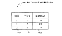
- FIG. 5 is an explanatory diagram showing an aggregation group change cost information table 1400.
- the aggregation group change cost information table 1400 is composed of records including the terminal 1401, the application 1402, and the change cost 1403.
- the change cost 1403 indicates the load of the network 130 and the server or the economic burden for changing the server 150 that provides the software resource.
- the change cost has a positive correlation with the amount of stored data in a requested communication characteristic information table 1100 described later. For example, for the combination of the terminal 170 and the application with a small storage data amount, the change cost 1403 is small because the amount of data transferred with the change of the server 150 is small.
- the network control server 100 determines to frequently change the aggregation group for the combination of the terminal 170 and the application whose change cost is low.
- Equation (9) the calculation method of the change cost Cm is exemplified in Equation (9).
- N is a set of servers i to which data moves in accordance with the change of the aggregation group.
- Ai is the amount of data that the server i moves
- bi is the bandwidth that can be used in the path through which the data of the moving server i moves
- ⁇ i is a predetermined coefficient of 0 to 1.
- FIG. 6 is an explanatory diagram showing an aggregation group destination information table 1500.
- the aggregation group destination information table 1500 includes one record including management information 1501 to 1503, rules 1504 to 1507, and actions 1508 to 1511.
- Management information includes an aggregation group 1501, a setting target communication device 1502, and a transfer destination communication device 1503.
- the aggregation group 1501 stores an identifier of a group in which terminals 170 having the same application (TCP port number) as the access destination server 150 are grouped.
- the setting target communication device 1502 is an identifier indicating the communication device 140 that sets a rule and an action.
- the identifier is, for example, an IP address for operation management.
- the transfer destination communication device 1503 is an identifier of the communication device 140 that is a destination to which the traffic is transferred when the traffic flows to the setting target communication device 1502.
- the rule is a condition for determining a processing method when traffic flows to the setting target communication device 1502.
- the rule includes a destination address 1504, a port number 1505, a transmission source address 1506, and a priority 1507.
- the destination address 1504 is a destination IP address of the received traffic.
- the port number is a TCP or UDP port number of the received traffic and identifies the application.
- the port number includes either the destination port number, the source port number, or both.
- a transmission source address 1506 is a transmission source IP address of the received traffic.
- the priority 1507 is a priority for the setting target communication device to determine which processing is to be performed when traffic matches a plurality of conditions.
- the action is a processing method when traffic flows to the setting target communication device 1502.
- the action includes an output destination address 1508, an output port number 1509, an output transmission source address 1510, and an output port 1511.
- the output destination address 1508 is a traffic destination IP address that is set when the traffic input to the setting target communication device 1502 is transferred to another server 150. When the output destination address 1508 is different from the destination address 1504 of the bank, this means that the destination IP address of the traffic is changed.
- the output port number 1509 is a port number of TCP or UDP traffic set when transferring traffic, similarly to the output destination address 1508. Similar to the output destination address 1508, the output source address 1510 is a traffic source address that is set when forwarding traffic that has entered the setting target. The output port 1511 indicates an identifier of a port that transmits traffic when the communication device 140 transfers. This port specifies from which port of the plurality of ports included in the communication device 140 the traffic is output.
- the server 150 that provides the software resource manages the combination of the same terminal 170 and application as an aggregation group, so that in the aggregation group destination information table 1500, rules and actions are based on the IP address of the server instead of the IP address of the terminal 170. Can be defined.
- the network control server 100 can reduce the number of messages transmitted to the setting target communication device 1502 as compared with the case where rules and actions are defined for each IP address of the terminal 170 that becomes a large amount. As a result, the processing load on the network control server 100 can be reduced.
- the number of IP addresses to be held is reduced and the table size is reduced as compared with the case where rules and actions are defined for each IP address of a large number of terminals 170. It is possible to reduce a processing load when the traffic transfer or discard processing 1502 is performed.
- IP address and port number 1505 are finite, and the number of IP addresses is exhausted particularly in IPv4.
- the rules and actions for the aggregation group instead of the combination of the terminal 170 and the application, the enlargement of the number of IP addresses and port numbers to be used can be reduced.
- FIG. 7 is an explanatory diagram showing the aggregation group destination change information table 1900.
- the aggregation group destination change information table 1900 manages the combination of the terminal 170 and the application to which the aggregation group to which the group belongs is changed in accordance with the movement of the server 150 that provides the software resource for a certain terminal 170 and application combination. However, this is information for managing an action different from the original aggregation group.
- the aggregation group destination change information table 1900 includes one record including management information 1901 to 1906, rules 1907 to 1910, and actions 1911 to 1914.
- the management information 1901 to 1906 includes a terminal 1901, an application 1902, a pre-change aggregation group 1903, a post-change aggregation group 1904, a setting target communication device 1905, and a transfer destination communication device 1906.
- the pre-change aggregation group 1903 is an identifier of the aggregation group to which the combination of the terminal 170 and the application belongs before the movement of the software resource.
- the changed aggregation group 1904 is an identifier of the aggregation group to which the combination of the terminal 170 and the application belongs after the movement of the software resource.
- the rules 1907 to 1910 and the actions 1911 to 1914 are the same as the rules 1504 to 1507 and the actions 1508 to 1511 of the aggregation group destination information table 1500.
- the communication device 140 basically determines the processing method based on the IP address and port number of the destination or transmission source server, not the IP address of the terminal 170.
- the software resource moves to a different server 150 and the aggregation group is changed, the traffic transmitted by the terminal 170 until the terminal 170 makes an inquiry to the service lookup server 120 and changes the destination IP address. Is an IP address of a server belonging to the original aggregation group. Therefore, the terminal 170 cannot connect to the server 150 to which software resources are provided until it makes an inquiry to the service lookup server 120.
- the aggregation group destination change information table 1900 defines the combination of the terminal 170 and the application whose aggregation group has been changed in the aggregation group destination information table 1500 based on the IP address and port number of the terminal 170 for a certain period.
- An action different from the action to be performed can be set in the setting target communication device 1905.
- the network control server 100 provides software resources by sending an instruction to change the communication path based on the IP address of the terminal 170 to the communication device 140. It can be set so that traffic from the terminal is forwarded to the destination server even after the server 150 moves until the terminal 170 makes an inquiry to the service lookup server.
- FIG. 8 is an explanatory diagram showing a communication characteristic information table 1700 between communication devices.
- the communication characteristic information table 1700 between communication apparatuses shows the communication characteristic between the communication apparatuses 140, and is measured or calculated by the path / resource calculation unit 208.
- the inter-communication apparatus communication characteristic information table 1700 includes a communication apparatus 1 (1701), a communication apparatus 2 (1702), a communication delay 1703, and a band 1704, and constitutes one record.
- the communication device 1 (1701) and the communication device 2 (1702) are identifiers of the communication device 140.
- Communication delay 1703 is an RTT between the communication device 1 and the communication device 2.
- a band 1704 is a traffic amount (bit rate) that can flow between the communication device 1 and the communication device 2.
- the communication delay 1703 and the bandwidth 1704 of the communication characteristic information table 1700 between communication apparatuses can be obtained by measurement using the ICMP (Internet Control Message Protocol) between the communication apparatuses 140 or between the servers 150 connected to the communication apparatus 140. it can.
- the RTT uses a preset value among the minimum value and the average value among the measured values.
- As for the bit rate a preset value among measured values, average values, or theoretical values is used.
- FIG. 9 is an explanatory view showing a communication characteristic information table 1800 between access points and communication devices.
- the access point-communication device communication characteristic information table 1800 shows communication characteristics between the communication devices 140, and is measured or calculated by the path / resource calculation unit 208.
- the inter-communication apparatus communication characteristic information table 1800 includes an access point 1801, a communication apparatus 1802, a communication delay 1803, and a band 1804, and constitutes one record.
- Access point 1801 is an identifier of access point 160.
- a communication delay 1803 is an RTT between the access point 160 and the communication device 140.
- Band 1804 is the amount of traffic (bit rate) that can flow between the access point 160 and the communication device 140.
- the communication delay 1803 and the bandwidth 1804 of the communication characteristic information table 1800 between the access point and the communication device are obtained by using ICMP (Internet Control Message Protocol) between the communication device and the access point or between the communication device and the server connected to the access point. It can be obtained by measuring.
- the RTT uses a preset value among the minimum value and the average value among the measured values.
- As for the bit rate a preset value among measured values, average values, or theoretical values is used.
- the network control server 100 uses the access point 1801 in the same table as the request delay of the communication characteristic information table 1700 between the communication apparatuses, the communication characteristic information table 1800 between the access points and the communication apparatus, and a request communication characteristic information table 1100 described later. For each combination of and application, the communication device 140 that satisfies the request delay, or a candidate for the communication device 140 can be selected.
- FIG. 10 is an explanatory diagram showing the requested communication characteristic information table 1100.
- the requested communication characteristic information table 1100 shows information on the combination of the terminal 170 and the application, and is used to determine which aggregation group the combination of the terminal 170 and the application belongs.
- the requested communication characteristic information table 1100 includes terminal / application basic information 1101 to 1105, a switchability flag 1108, request delays 1107 to 1108, request priority 1109, request bandwidth 1110 to 1111, storage data amount 1112, and access point 1113. Including one record.
- the terminal / application basic information 1101 to 1105 includes a terminal 1101, a terminal address 1102, a port number 1103, an application 1104, a session 1105, and a switchability flag 1106.
- the terminal 1101 stores the identifier of the terminal 170.
- a terminal address 1102 indicates the IP address of the terminal 170.
- the port number 1103 indicates a TCP or UDP port number of traffic transmitted from the terminal 170.
- the session 1105 is a session owned for each combination of the terminal 170 and the application, and is, for example, a cookie.
- the switchability flag 1106 indicates whether or not the communication device 140 may change the destination to the servers 150 belonging to the same aggregation group.
- Request delay includes communication delay (between terminal and server) 1107 and communication delay (between servers) 1108.
- a communication delay (between terminal and server) 1107 indicates a threshold value of communication delay required between the access point 106 and the server 150, and means that a value equal to or less than this threshold value is requested.
- Communication delay (between servers) 1108 indicates a threshold value of communication delay required between servers 150, and means that a value equal to or less than this threshold value is requested.
- the request priority 1109 stores the priority when performing QoS.
- the requested bandwidth includes a bandwidth (between terminal and server) 1110 and a bandwidth (between servers) 1111.
- the bandwidth (between terminal and server) 1110 indicates a threshold value of the bandwidth required between the access point 160 and the server 150, and means that a value greater than this threshold value is requested.
- the bandwidth (between servers) 1111 indicates a threshold value of the bandwidth required between the servers 150, and means that a value greater than this threshold value is requested.
- the storage data amount 1112 indicates the amount of data (bytes) held by the server 150.
- the access point 1113 indicates the identifier of the access point 160 to which the combination of the terminal 170 and the application is most frequently connected.
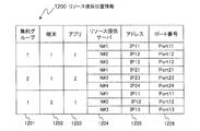
- FIG. 11 is an explanatory diagram showing a resource providing location information table 1200.
- the resource providing location information table 1200 is information that the network control server 100 receives from the resource management server 110, and indicates the location of the server 150 where the software resource is provided.
- the resource provision location information table 1200 includes an aggregation group 1201, a terminal 1202, an application 1203, a resource provision server 1204, an address 1205, and a port number 1206.
- the identifiers are stored in the aggregation group 1201, the terminal 1202, and the application 1203, respectively.
- the resource providing server 1204 indicates the identifier of the server 150 that provides the software resource for each combination of the terminal 170 and the application.
- the resource providing server 1204, the address 1205, and the port number 1206 may each have a plurality of values, but the resource providing server 1204, the address 1205, and the port number 1206 are managed in association with each other in a predetermined order.
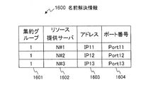
- FIG. 12 is an explanatory diagram showing the name resolution information table 1600.
- the name resolution information table 1600 is included in the name resolution request that the network control server 100 transmits to the resource management server 110 in a sequence 2135 of FIG.
- the name resolution information table 1600 includes an aggregation group 1601 that stores the aggregation group, a resource providing server 1602 that stores the name or identifier of the server 150 corresponding to the aggregation group, and an address 1603 that stores the IP address of the server 150. And a port number 1604 used by the application.
- the name or identifier of the server 150 can be composed of, for example, a URL or a domain name.
- FIG. 13 is an explanatory diagram showing the setting information table 1950.
- the setting information table 1950 is generated by the network control server 100 for each of the communication devices 140-1 and 140-2 in a sequence 2130 in FIG. 14 to be described later.
- the network control server 100 in the sequence 2130 in FIG. Included in the setting change transmitted to each of the communication apparatuses 140-1 and 140-2.
- the setting information table 1950 includes rules 1951 to 1954 and actions 1955 to 1958.
- Rules 1951 to 1954 indicate conditions for the communication device 140 that has received the traffic to determine the processing method.
- the rules 1951 to 1954 include a destination address 1951, a port number 1952, a transmission source address 1953, and a priority level 1954.
- a destination address 1951 indicates a destination IP address included in the header of the received traffic.
- the port number 1952 indicates a port number such as TCP or UDP included in the header of the received traffic.
- a transmission source address 1953 indicates a transmission source IP address included in the header of the received traffic.
- the priority level 1954 indicates a value for determining which process (action) corresponding to which rule is preferentially applied when the received traffic applies to a plurality of rules. However, if the communication state cannot be normally communicated due to congestion, failure, or maintenance, a process (action) corresponding to the rule with the highest priority is applied to the rule that cannot communicate normally.
- the destination address 1955 indicates a destination IP address attached to the header of the traffic when forwarding.
- the port number 1956 indicates a port number such as TCP or UDP attached to a traffic header when forwarding.
- a transmission source address 1957 indicates a transmission source IP address attached to a traffic header when forwarding.
- the output port 1958 is a number that identifies the position of the port that the communication device 140 outputs.
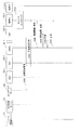
- FIGS. 14A and 14B are sequence diagrams illustrating processing for performing aggregation group determination and destination / route switching setting according to this embodiment.
- the terminal 170-1 performs a service lookup.
- service lookup in order to view or update software resources provided by the server 150 on the screen of the terminal 170, the terminal 170 needs to be connected to the server 150-1 or 150-2. Indicates that the IP address of the server 150 to be inquired.
- the service lookup is started when the user of the terminal 170 starts or restarts the application, or periodically by a timer function provided in the terminal 170.
- the network control server 100 By periodically starting the lookup, the network control server 100 deletes the setting information for each terminal / application in step 5630 of FIG. 23 after a certain period (a time longer than the period in which the terminal 170 executes the lookup). can do.
- the terminal 170-1 transmits a name resolution request to the service lookup server 120.
- the name resolution request includes the domain name that provides the software resource.
- This domain name is an identifier of the server 150 that provides software resources that are uniquely determined for each combination of the terminal 170 and the application.
- the service lookup server 120 transmits a name resolution response to the terminal 170-1.
- the name resolution response includes an IP address corresponding to the domain name and a port number. If the service lookup server 120 does not have an IP address and a port number corresponding to the domain name for the combination of the terminal 170 and the application that received the inquiry, the service lookup server 120 will receive the IP of the default server 150. Reply address.
- the service lookup server 120 transmits a name resolution request reception notification to the resource management server 110.
- the name resolution request reception notification includes the IP address and port number of the source of the name resolution request in sequence 2020, and the IP address and port number of the server notified in step 2030.
- the sequence 2040 may be omitted.
- the resource management server 110 notifies the network control server 100 of a resource provision location request 2050.
- the resource provision location request shown in FIG. 11 includes a requested communication characteristic information table 1100.
- the network control server 100 determines a resource providing position. In determining the resource providing position, the network control server 100 refers to the requested communication characteristic information table 1100, the communication characteristic information table between communication apparatuses 1700, the communication characteristic information table between access points and communication apparatuses 1800, and the aggregation group information table 1300. Then, the resource providing position information table 1200 is calculated, and the aggregation group information table 1300 is updated.
- FIG. 19 is a flowchart illustrating an example of processing in which the aggregation group determination unit 201 and the aggregation group generation / change unit 204 determine an aggregation group.
- step 5020 when the aggregation group determination unit 201 receives the requested communication characteristic information table 1100 illustrated in FIG. 4 from the message transmission / reception unit 210, the aggregation group determination unit 201 refers to the aggregation group information table 1300 and determines whether there is an aggregation group that satisfies the requirement. Determine whether.
- the aggregation group determination unit 201 includes the terminal 1101 of the terminal / application basic information, the application 1104, the switchability flag, the communication delay of the request delay (between the terminal and the server) 1107, the communication delay (between the servers) of the request communication characteristic information table 1100. 1108, the storage data amount 1112 and the access point 1113 are acquired.
- the aggregation group determining unit 201 has a communication characteristic information communication delay 1303 in the aggregation group information table 1300 shown in FIG. 4 that is smaller than the communication delay (between servers) 1108 acquired in this step, and the communication characteristic information bandwidth.
- the aggregation group 1301 larger than the bandwidth (between servers) 1111 acquired by this step 1304 and the server 1302 that provides software resources are selected.
- the aggregation group determination unit 201 includes an access point 1801 of the access point-communication apparatus communication characteristic information table 1800 illustrated in FIG. 9 and an access point 1113 of the requested communication characteristic information table 1100 acquired by the communication apparatus 1802 in this step.
- the communication delay 1803 and the band 1804 of the line are acquired. Further, access in a row where the communication delay 1803 is smaller than the communication delay (terminal-server) 1107 acquired in this step and the band is larger than the bandwidth (terminal-server) 1111 acquired in this step.
- a point 1801, a communication device 1802, a communication delay 1803, and a band 1804 are acquired.
- the acquired candidates for the access point 1801, the communication device 1802, the communication delay 1803, and the band 1804 are hereinafter referred to as an access point candidate, a communication device candidate, a communication delay candidate, and a band candidate, respectively.
- the resource providing server 1302 of the aggregation group information table 1300 illustrated in FIG. 4 acquires the aggregation group 1301 and the cost 1307 of the row included in the communication device candidate.
- the acquired aggregation group 1301 and cost 1307 are referred to as an aggregation group candidate and a cost candidate, respectively.
- step 5040 If there are one or more aggregation group candidates, the process proceeds to step 5040. If there is no aggregation group candidate, the process proceeds to step 5030.
- step 5030 the aggregation group creation / change unit 204 adds a new aggregation group to the aggregation group information table 1300.
- the added aggregation group is referred to as a new aggregation group.
- the aggregation group generation / change unit 204 adds communication device candidates to the resource providing server 1302 in the new aggregation group row of the aggregation group information table 1300.
- a combination of communication device candidates in which the total of communication delay candidates is equal to or smaller than a predetermined threshold or the total of band candidates is greater than a predetermined threshold is selected and adjacent to the communication device 140 Get the server.
- the selected communication device candidate is called a new communication device
- the acquired server 150 is called a new resource providing server.
- the number of resource providing servers 1302 registered in the aggregation group can be reduced, and an increase in the number of IP addresses and port numbers required for the number of resource providing server combinations in the aggregation group can be suppressed. Can do.
- the aggregation group generation / change unit 204 determines the communication device with the smallest communication delay candidate as the communication delay candidate,
- the corresponding server is a new resource providing server.
- the communication device 140 does not receive a notification from the resource management server 110, and changes the destination when a failure or congestion occurs or a change in the destination associated with a change in the access point to which the terminal 170 is connected.
- the combination of the terminal 170 and the application that are autonomously performed in FIG. 6 and the combination of the terminal 170 and the application that are not autonomously performed can coexist.
- the aggregation group generation / change unit 204 includes a communication delay 1703 and a bandwidth 1704 of a row in which the communication device 1 (1701) and the communication device 2 (1702) of the communication characteristic information table 1700 illustrated in FIG. ,
- the maximum value of the acquired communication delay 1703 is acquired as the maximum communication delay
- the minimum value of the band 1704 is acquired as the minimum band.
- the aggregation group creation / change unit 204 adds a new resource provision server to the resource provision server 1302 in the row of the new aggregation group, adds a maximum communication delay to the communication delay 1303, adds a minimum band to the band 1304, and The terminal 170 acquired in Step 5010 is added to 1305, and the application acquired in Step 5020 is added to the application 1306.
- step 5080 After executing the processing of step 5030, the process proceeds to step 5080.
- step 5040 the aggregation group determination unit 201 determines whether to change the aggregation group.
- the aggregation group determination unit 201 determines whether there are rows that are the terminal 1101 and the application 1104 of the requested communication characteristic information table 1100 acquired by the terminal 1305 and the application 1306 of the aggregation group information table 1300 in step 5020, respectively. If it exists, the aggregation group of the bank is acquired. Hereinafter, the acquired aggregation group is referred to as an existing aggregation group.
- the aggregation group determination unit 201 compares the communication delay 1303, the band 1304, and the cost 1307, which are the same as those of the existing aggregation group, with the communication delay candidate, the band candidate, and the cost candidate acquired in step 5020.
- the communication delay 1303 accompanying the existing aggregation group is larger than the communication delay candidate
- the band 1304 accompanying the existing aggregation group is smaller than the band candidate
- the cost 1307 accompanying the existing aggregation group is larger than the cost candidate. In this case, it is determined to change the aggregation group.
- the aggregation group determination unit 201 uses the change cost 1403 of the row in which the terminal 1401 and the application 1402 in the aggregation group change cost information table 1400 illustrated in FIG. 5 match the terminal 1101 and the application 1104 in the requested communication characteristic information table 1100. It may be determined that the aggregation group is to be changed when the cost associated with the existing aggregation group is greater than the sum of the cost candidate and the change cost 1403.
- the aggregation group determination unit 201 can determine whether or not the aggregation group needs to be changed in consideration of the load accompanying the change of the aggregation group. As the communication delay and bandwidth between the communication devices 140 change in a short period, it is possible to prevent the optimum aggregation group from changing frequently for the combination of the terminal 170 and the application.
- the bandwidth of the network 130 is consumed by the traffic that flows because the server 150 that provides software resources moves due to the change of the aggregation group, and communication between the terminal 170 and the server 150 or between the server 150 and the server 150 is performed. It is possible to prevent the band from being compressed. In addition, when the software resource is moved between the servers 150, it is possible to prevent the CPU 150 and the memory resources of the server 150 from being compressed by the server 150 deleting and adding the software resource.
- step 5050 If it is determined to change the aggregation group, the process proceeds to step 5050. If it is determined not to change the aggregation group, the process proceeds to step 5045.
- the aggregation group determination unit 201 notifies the resource management server 110 via the message transmission / reception unit 210 that the resource provision position is not changed. For example, the aggregation group determination unit 201 transmits an empty resource provision position information table 1200 to the resource management server 110 via the message transmission / reception unit 210.
- the aggregation group determining unit 201 determines in step 5040 that the communication delay 1303 accompanying the existing aggregation group is larger than the communication delay candidate, or the band 1304 accompanying the existing aggregation group is smaller than the band candidate, or Then, the candidate aggregation group determined that the cost 1307 accompanying the existing aggregation group is higher than the cost candidate is acquired as the change destination aggregation group.
- the aggregation group generation / change unit 204 sets the change destination aggregation group and the terminal 1101 and the application 1104 acquired in step 5020 to the aggregation group 1201 in the new row of the resource provision location information table 1200 illustrated in FIG.
- the resource provision server in the row where the aggregation group of the aggregation group information table 1300 is the change destination aggregation group is added to the resource provision server 1204 in the bank 1202 and the application 1203.
- the aggregation group creation / change unit 204 adds an IP address that is a combination of an unused address and a port number and a port number to the address 1205 and the port number 1206 in the resource provision location information table 1200.
- step 5070 the aggregation group determination unit 201 transmits the resource provision location information table 1200 added in step 5060 to the resource management server 110 via the message transmission / reception unit 210.
- the network control server 100 After performing the processing of step 5070, the network control server 100 enters a standby state, and proceeds to C of FIG. 21 when receiving a destination / route setting request in the sequence 2110 of FIG. 14A.
- the aggregation group creation / change unit 204 creates a resource provision location information table 1200.
- the aggregation group creation / change unit 204 adds the new aggregation group and the terminal 1101 and the application 1104 acquired in step 5020 to the aggregation group 1201, the terminal 1202, and the application 1203 in a new row of the resource provision location information table 1200.
- a new resource providing server is added to the resource providing server 1204 of the bank, and an unused address and a port number are added to the address 1205 and port number 1206 of the bank.
- step 5090 the aggregation group determination unit 201 transmits the resource providing location information table 1200 added in step 5080 to the resource management server 110 via the message transmission / reception unit 210.
- the network control server 100 After performing the processing of Step 5090, the network control server 100 enters a standby state, and proceeds to A of FIG. 20 when a destination / path setting request is received in the sequence 2110 of FIG. 14A.
- the network control server 100 can assign the aggregation group based on the communication characteristics required for each combination of the terminal 170 and the software and the position of the terminal 170 on the network 130.
- the network control server 100 transmits the resource providing position information to the resource management server 110.
- the resource providing position information includes the resource providing position information table 1200 shown in FIG.
- the resource management server 110 transmits a resource movement / duplication request 2080 to the resource providing server 1204 (servers 150-1 and 150-2) specified by the resource providing location information table 1200.
- the server 150-1 moves or copies the software resource specified by the message to the server 150-2 based on the message received by the resource move / copy request.
- the server 150-1 and the server 150-2 are synchronized so that when the terminal 170-1 updates the data for the resource of either server, the other server is updated. Reflected.
- the server 150-1 and the server 150-2 notify the resource management server 110 that the migration or copying of the software resource has been completed.
- the resource management server 110 transmits a destination / route setting request to the network control server 100.
- the destination / route setting request includes a requested communication characteristic information table 1100.
- the terminal / application basic information is transmitted. 1101 to 1105 may be transmitted.
- the network control server 100 generates destination / path setting information in order to set a communication path in the communication apparatus 140.
- FIGS. 20 and 21 are explanatory diagrams showing destination / route setting information generation processing when a new software resource is added.
- FIGS. 22 to 24 show the case where the combination of the terminal 170 and the application is changed to a different aggregation group. It is explanatory drawing which shows the process of destination / route setting information generation.
- FIG. 20 is a flowchart illustrating an example of processing in which the aggregation group address management unit 202 generates setting information for the communication device when an aggregation group is added.
- FIG. 21 is a flowchart illustrating an example of processing in which the route / destination setting unit 209 sets a route and a destination in the communication device 140 when an aggregation group is added.
- FIG. 22 is a flowchart illustrating an example of processing in which the aggregation group address management unit 202 generates setting information for the communication device 140 when the aggregation group is changed.
- FIG. 20 is a flowchart illustrating an example of processing in which the aggregation group address management unit 202 generates setting information for the communication device when an aggregation group is changed.
- FIG. 23 is a flowchart illustrating an example of processing in which the aggregation group address management unit generates setting information for the communication device for each combination of a terminal and an application when the aggregation group is changed.
- FIG. 24 is a flowchart illustrating an example of processing in which the route / destination setting unit 209 sets a route and a destination in the communication device when the aggregation group is changed.
- the aggregation group address management unit 202 determines whether or not a new aggregation group is stored in the aggregation group 1501 of the aggregation group destination information table 1500 shown in FIG. When a new aggregation group is stored in the aggregation group 1501, the process proceeds to F in FIG. On the other hand, if a new aggregation group is not stored in the aggregation group 1501, the process proceeds to step 5120.
- step 5120 the aggregation group address management unit 202 adds information on the new aggregation group to the aggregation group destination information table 1500.
- the aggregation group address management unit 202 adds a new aggregation group to the aggregation group 1501 of the aggregation group destination information table 1500, and adds a new communication device to the setting target communication device 1502 of the bank. When there are a plurality of new communication devices, the aggregate group address management unit 202 adds the new communication device to the transfer destination communication device 1503 so that it becomes a brute force. When the same value is input to the setting target communication device 1502 and the transfer destination communication device 1503, it means that the data is not transferred to another communication device 140.
- the aggregation group 1201 of the resource provision location information table 1200 is a new aggregation group, and the resource provision server 1204 has the destination address 1504 and port number 1505 of the aggregation group destination information table 1500 in the same row.
- the address 1205 and the port number 1206 of the row that is the setting target communication device 1502 added in this step are added.
- the address 1205 and the port number 1206 are referred to as a pre-transfer address and a pre-transfer port number, respectively.
- the aggregation group address management unit 202 adds “arbitrary” meaning an arbitrary address to the transmission source address 1506 in the same group of the aggregation group destination information table 1500, and the setting target communication device 1502 is added to the priority 1507 in the same line.
- the transfer destination communication device 1503 is the same row, 3 indicating medium priority is added to the priority, and when the setting target communication device 1502 and the transfer destination communication device 1503 are different, 4 having a priority lower than 3 is added.
- the aggregation group address management unit 202 sets the destination address 1504 of the same line to the output destination address 1508 and the output port number 1509 when the setting target communication device 1502 and the transfer destination communication device 1503 of the aggregation group destination information table 1500 are in the same row. , And a port number 1505 is added. Then, the aggregation group address management unit 202 adds “no change” to the output transmission source address 1510 of the aggregation group destination information table 1500, which means that it does not change from the destination address of the received traffic, and adds it to the output port. Add the port number connected to the adjacent resource provider server.
- the aggregation group address management unit 202 is adjacent to the setting target communication device 1502 in the output destination address 1508 and the output port number 1509 in the row where the setting target communication device 1502 and the transfer destination communication device 1503 in the aggregation group destination information table 1500 are different.
- an unused IP address and port number are added.
- the address and port number added here will be referred to as transfer address and transfer port number below.
- the aggregation group address management unit 202 sets the transfer address to the address 1205 and the port number 1206 in the row where the aggregation group of the resource provision location information table 1200 in FIG. 11 is the new aggregation group and the resource provision server is the new resource provision server. And add the transfer port number.
- the aggregation group address management unit 202 adds a new aggregation group to the aggregation group 1501 of the aggregation group destination information table 1500, adds a new communication device to the setting target communication device 1502 and the transfer destination communication device 1503, and A transfer destination address and a transfer destination port number are added to the transmission source address 1506 and the port number 1505, and 3 indicating medium priority is added to the priority.
- the aggregate group address management unit 202 adds “no change” to the output destination address 1508, which means that the destination address of the received traffic is not changed.
- the aggregation group address management unit 202 adds the pre-transfer address and the pre-transfer port number to the output port number 1509 and the output source address 1510, respectively.
- the network control server 100 adds another new communication device included in the same aggregation group (new aggregation group) to the transfer destination communication device 1503 for each new communication device included in the new aggregation group.
- the network control server 100 instructs the communication device 140 to perform a process of transferring to the adjacent server 150 having a medium priority in normal times.
- the network control server 100 When the network control server 100 switches communication to another server 150 due to a communication failure or congestion between the communication device 140 and the adjacent server 150, or a failure or maintenance in the adjacent server 150, the network control server 100 When the terminal 170 transmits an IP address as a destination IP address, a process of changing the destination to a server that is the same aggregation group via another transfer destination communication device having a low priority and transmitting the IP address Can be instructed.
- the communication device 140 can autonomously switch the destination according to the instruction at the time of the failure, congestion, or maintenance, so that the destination switching time at the time of the failure can be shortened.
- the communication device 140 does not request the network control server 100 for a processing method instruction, a plurality of communication devices 140 request the network control server 100 for each aggregation group to compress CPU and memory resources. Can be prevented.
- the same destination address 1504 and port number 1505 are added to the output destination address 1508 and the output port number 1509, and the output source address 1510 is not changed from the destination address of the received traffic. “No change” is added, and the port number of the communication device 140 connected to the adjacent server 150 is added to the output port 1511.
- the transmission source address 1504 and the port number 1505 are transferred to the transfer destination communication device 1503 that is the same as the setting target communication device 1502 instructing to change the transfer destination address and the transfer destination port number. It is possible to set processing for changing the port number 1506 and the port number 1505 to the address before transfer and the port number before transfer. Therefore, the traffic does not necessarily have to pass through the setting target communication device 1502 as compared with the case where the transmission source address 1506 and the port number 1505 are changed in the setting target communication device 1502 in which the destination address 1504 and the port number 1505 are changed. The number of communication devices 140 that pass through decreases, traffic communication delay decreases, and bandwidth consumption of the communication devices 140 that pass through can be reduced.
- step 5220 After performing the processing of step 5220, the process proceeds to B of FIG.
- FIG. 21 is a flowchart showing processing for setting a destination and a communication path for the communication device 140.
- the route / destination setting unit 209 acquires the setting target communication device 1502 of the row added to the aggregation group destination information table 1500 by the aggregation group address management unit 202 in step 5120.
- the setting information table 1950 is set for each setting target communication device 1502. Generate.
- step 5530 the route / destination setting unit 209 transmits the setting information table 1950 corresponding to each communication device 140 to each setting target communication device acquired in step 5520 via the communication IF 210.
- the aggregation group determination unit 201 adds a new aggregation group to the aggregation group 1601 of the name resolution information table 1600 illustrated in FIG. 12, and assigns the resource group to the resource providing server 1602, the address 1603, and the port number 1604, respectively.
- a resource providing server 1204, an address 1205, and a port number 1206 in a row in which the aggregation group of the resource providing position information table 1200 is a new aggregation group are added.
- the aggregation group determination unit 201 transmits the name resolution information table 1600 to the resource management server 110 via the message transmission / reception unit 210.
- step 5540 When the processing of step 5540 is performed, the destination and communication path setting processing for the communication device 140 is completed.
- FIG. 22 is a flowchart showing a process for calculating a destination and a communication route when the terminal 170 and the application combination are changed to different aggregation groups.
- Steps 5210 and 5220 are obtained by changing a part that is a new aggregation group in Step 5110 and Step 5120 of FIG. 20 to a change destination aggregation group.
- step 5210 if it is determined that the aggregation group selected in step 5050 exists in the aggregation group destination information table 1500, the process proceeds to G instead of F in FIG.
- FIG. 23 is a flowchart showing a process for calculating a destination and a communication path for changing a destination based on a transmission source address when the terminal 170 and the application combination are changed to different aggregation groups.
- the terminal / application management unit 205 refers to the aggregation group destination information table 1500 and acquires information on the change destination aggregation group.
- the terminal / application management unit 205 acquires management information 1501 to 1503, rules 1504 to 1507, and actions 1508 to 1511 for rows in which the aggregation group 1501 of the aggregation group destination information table 1500 is the change destination aggregation group.
- step 5320 the terminal / application management unit 205 refers to the requested communication characteristic information table 1100 received in step 5010, and acquires the terminal 1101 and the application 1104.
- step 5330 the terminal / application management unit 205 determines whether or not the changed aggregation group information exists in the aggregation group destination change information table 1900.
- the terminal / application management unit 205 includes the terminal 1901 and the application 1902 in the aggregation group destination change information table 1900 that are the terminal 1101 and the application 1104 acquired in step 5020, and the post-change aggregation group is the change-destination aggregation group. Determine whether a row exists. If there is a row in which the post-change aggregation group is the change-destination aggregation group, the process proceeds to G in FIG. On the other hand, if it does not exist, the process proceeds to step 5340.
- step 5340 the terminal / application management unit 205 adds a new change destination aggregation group to the aggregation group destination change information table 1900.
- the terminal / application management unit 205 adds the terminal 1901 and the application 1902 of the aggregation group destination change information table 1900, the terminal 1101 and the application 1104 acquired in step 5320, and acquires the aggregation group before the change in step 5040 of FIG. An existing aggregation group is added, and the change destination aggregation group acquired in step 5050 of FIG. 19 is added to the post-change aggregation group.
- the terminal / application management unit 205 stores the setting target communication device 1905, transfer destination communication device 1906, rules 1907 to 1910, and actions 1911 to 1914 in the aggregation group destination change information table 1900 in the aggregation group destination information table 1500, respectively.
- a setting target communication device 1502, a transfer destination communication device 1503, rules 1504 to 1507, and actions 1508 to 1511 in a row whose aggregation group is a change destination aggregation group are added, and the following three points are changed.
- the terminal / application management unit 205 sets the destination address 1907 of the aggregation group destination change information table 1900 to the address of the terminal 1101 acquired in step 5020. .
- the terminal / application management unit 205 obtains the transmission source address 1909 of the aggregation group destination change information table 1900 in step 5020 and the address of the terminal 1101 To.
- the terminal / application management unit 205 sets the priority 1910 of the aggregation group destination change information table 1900 to 1 which means highest priority when the priority of the aggregation group destination information table 1500 is 3, which is medium priority. If the priority is low, it is set to 2 which means high priority.
- step 5340 After performing the process of step 5340, the process proceeds to E of FIG.
- FIG. 24 is a flowchart showing processing for setting the destination and the communication path for the communication device 140 when the terminal 170 and the application combination are changed to different aggregation groups.
- step 5620 the route / destination setting unit 209 generates setting information for each setting target communication device.
- step 5220 the aggregation group address management unit 202 acquires the setting target communication device 1502 added to the aggregation group destination information table 1500, and the rules 1504 to 1507 and the actions of the rows in which the setting target communication device 1502 is the same. 1508 to 1511 are added to the rules 1951 to 1954 and the actions 1955 to 1958 of the setting information table 1950.
- the route / destination setting unit 209 acquires the setting target communication device 1905 of the row added to the aggregation group destination change information table 1900 by the aggregation group address management unit 202 in step 5340, and the setting target communication device 1905 is the same.
- the rules 1951 to 1954 and the actions 1955 to 1958 of the setting information table 1950 are added to the contents added based on the aggregation group destination change information table 1900.
- step 5630 the route / destination setting unit 209 transmits the setting information table 1950 corresponding to each communication device 140 to each setting target communication device acquired in step 5620 via the communication IF 210.
- the aggregation group determination unit 201 adds a new aggregation group to the aggregation group 1601 of the name resolution information table 1600, and adds the resource provision server 1602, address 1603, and port number 1604 to the resource provision location information table.
- a resource providing server 1204, an address 1205, and a port number 1206 in a row in which the aggregation group of 1200 is a change destination group are added.
- the aggregation group determination unit 201 transmits the name resolution information table 1600 to the resource management server 110 via the message transmission / reception unit 210.
- step 5640 When the processing of step 5640 is performed, the destination and communication path setting processing for the communication device 140 is completed.
- the terminal 170 has the address of the server 150 that originally provided the software resource, Even when transmission is performed with the port number as the destination, the communication device 140 can autonomously transfer the destination to the server 150 provided with software resources. As a result, after the software resource moves, the terminal 170 can continue to use the software resource even before performing the service lookup.
- the network control server 100 may instruct the setting target communication device to delete the terminal / app-specific setting information set in step 5630 after a certain period of time or when notified from the resource management server 110.
- the fixed period is an arbitrary time longer than the time during which the terminal 170 performs the lookup in the sequence 2010 of FIG.
- the network control server 100 transmits a setting change message to the setting target communication device 1502 in the column added to the aggregation group destination information table 1500.
- the setting change message includes a setting information table 1950.
- the network control server 100 notifies the resource management server 110 of the completion of destination / route setting.
- the destination / route setting completion notification includes a name resolution information table 1600.
- the resource management server 110 notifies the service lookup server 120 of a name resolution change request.
- the name resolution change request notification includes a name resolution information table 1600.
- the resource management server 110 transmits a resource movement / duplication post-processing request to the server 150-1 that has transmitted the resource movement / duplication request in step 2080.
- the resource migration / post-replication processing includes deleting information (software resources) existing in the server 150-1 that is no longer necessary as the software resource is migrated from the server 150-1 to 150-2. It is. This step can be omitted when the resource migration / replication post-processing is unnecessary.
- the server 150-1 executes the above-described resource migration / replication post-processing.
- the software resource moves from the server 150-1 to the server 150-2, and the aggregation group to which the terminal 170-1 belongs is accessed to the server 150-2.
- 15 to 18 are sequence diagrams showing processing in which the terminal 170 in the present embodiment browses or updates software resources.
- FIG. 15 shows that the terminal 170 performs software processing immediately after the processing of the sequence diagrams of FIGS. 14A and 14B described above is performed and before the processing equivalent to the processing of the sequence 2010 to the sequence 2030 is performed again.
- It is a sequence diagram which shows the process which carries out browsing or an update request
- the terminal 170-1 transmits information browsing / update to the server 150-1.
- the destination IP address and port number of the information browsing / updating traffic are the IP address and port number indicated in the name resolution response last received by the terminal 170-1 from the service lookup server 120, and the source IP address is This is the IP address of terminal 170-1 itself.
- the communication device 140-1 changes the destination when receiving the information browsing / updating traffic transmitted by the terminal 170-1 in the sequence 2210.
- the communication device 140-1 acquires the destination IP address, port number, and source IP address of the received traffic, and performs the processing specified in the actions 1955 to 1958 on the lines that match the rules 1951 to 1954 of the setting information table 1950. Perform on received traffic.
- the communication device 140-1 transmits the traffic to the communication device 140-2.
- the communication device 140-2 transfers the received information browsing / update traffic to the server 150-2.
- server 150-2 transmits a response to information browsing / update to communication device 140-2.
- the source IP address and port number described in the header of the traffic that received the destination IP address were received, and the port number and source IP address described in the header of the received traffic were received.
- the destination IP address described in the traffic header is used.
- the communication device 140-2 when the communication device 140-2 receives the response traffic transmitted by the server 150-2 in the sequence 2250, the communication device 140-2 changes the destination.
- the communication device 140-2 acquires a destination IP address, a port number, and a transmission source IP address of the received traffic, and performs processing specified in the actions 1955 to 1958 on the line that matches the rules 1951 to 1954 of the setting information table 1950. Perform on received traffic.
- the communication device 140-2 transfers the received information browsing / update traffic to the terminal 170-1.
- FIG. 16 shows that the terminal 170 provides software resources when the same processing as the processing of the sequence 2010 to the sequence 2030 is executed again after the processing of the sequence diagram shown in FIGS. 14A and 14B is performed. It is a sequence diagram which shows the process which carries out browsing or an update request
- terminal 170-1 performs a service lookup.
- the service lookup is started after the application is started or restarted by the user of the terminal 170 or periodically by the timer function of the terminal 170-1.
- the terminal 170-1 transmits a name resolution request to the service lookup server 120.
- the service lookup server 120 transmits a name resolution response to the terminal 170-1.
- the name resolution response includes an IP address corresponding to the domain name and a port number.
- terminal 170-1 transmits information browsing / update to server 150-2.
- the destination IP address and port number of the information browsing / updating traffic are the IP address and port number indicated in the name resolution response last received by the terminal 170-1 from the service lookup server 120, and the source IP address is It is its own IP address.
- the communication device 140-2 transfers the received information browsing / update traffic to the server 150-2.
- the server transmits a response to information browsing / updating to the communication device 140-2.
- the source IP address described in the header of the traffic that received the destination IP address the port number described in the header of the traffic that received the port number, and the traffic that received the source IP address
- the server 150-2 transmits information browsing / update traffic to the communication device 150-2.
- the communication device 140-2 transfers the received information browsing / update traffic to the terminal 170-1.
- FIG. 17 is a sequence diagram showing processing when a failure occurs between the communication device 140-1 and the server 150-1 or in the server 150-1.
- the communication device 140-1 detects a failure.
- the failure is a communication failure such as a link down or congestion between the communication device 140-1 and the server 150-1, a failure in the server 150-1 such as an application of the server 150-1 being down, or a system stop due to maintenance. Show.
- the communication device 140-1 detects the failure of the server 150 from the port down of the communication device 140-1. In the detection of the failure in the server 150-1, the communication device 140-1 determines the heartbeat traffic between the server 150-1 and the server 150-2 from the destination IP address, port number, and source IP address of the traffic. By identifying and monitoring the amount of traffic going up and down, the amount of heartbeat traffic from the server 150-1 decreases at the time of failure in the server 150, so that a failure is determined.
- failure detection may be performed by the resource management server 110 or the network control server 100 instead of the communication device 140-1, and notified to the communication device 140-1.
- the communication device 140-1 transmits the details of the failure that has occurred to the network control server 100.
- the network control server 100 transmits the failure content received from the communication device 140-1 to the resource management server 110.
- the resource management server 110 obtains that a failure has occurred in the server 150-1 from the failure content message received in sequence 2430 in the information of the name resolution information table 1600 and obtains the name resolution information table 1600. Then, the IP address of the server 150-1 is changed to the IP address of the server 150-2 belonging to the same aggregation group.
- the resource management server 110 transmits a name resolution change notification to the service lookup server 120.
- the name resolution change notification includes the updated name resolution information table 1600 in sequence 2435.
- the processing from information browsing or updating in sequence 2450 to response in sequence 2520 is the same as the processing from sequence 2210 to sequence 2270 in FIG.
- terminal 170 After a series of processing from sequence 2410 to sequence 2440 is performed, when processing equivalent to the processing from sequence 2010 to sequence 2030 in FIG. 14 is executed again, terminal 170 provides server 150 that provides software resources. On the other hand, the process of requesting browsing or updating is the same as sequence 2310 to sequence 2370 in FIG.
- FIG. 18 shows again from sequence 2010 to sequence 2030 in FIG. 14 after the terminal 170 for browsing or updating information moves from the server 150-1 and the nearest server moves from the server 150-1 to the server 150-2. It is explanatory drawing which shows the process which the terminal 170 requests
- the terminal 170-1 transmits information browsing / update to the server 150-1.
- the destination IP address and port number of the information browsing / updating traffic are the IP address and port number indicated in the name resolution response last received by the terminal 170-1 from the service lookup server 120, and the source IP address is It is its own IP address.
- the communication device 140-1 transfers the received information browsing / update traffic to the server 150-1.
- the server transmits a response to information browsing / update to the communication device 140-1.
- the source IP address described in the header of the traffic that received the destination IP address the port number described in the header of the traffic that received the port number, and the traffic that received the source IP address
- the communication device 140-1 transmits traffic in response to information browsing / update to the terminal 170-1.
- sequence 2650 as the terminal 170-1 moves, the access point 160 to which the terminal 170-1 is connected is changed to an access point 160-2 having a smaller RTT to the server 150-2 than to the server 150-1.
- terminal 170-1 transmits information browsing / update to server 150-1.
- the destination IP address and port number of the information browsing / updating traffic are the same as the destination IP address and port number of the information browsing / updating traffic transmitted by the terminal 170-1 in the sequence 2610.
- the communication device 140-2 changes the destination when receiving the information browsing / updating traffic transmitted by the terminal 170-1 in sequence 2660.
- the communication device 140-2 acquires a destination IP address, a port number, and a transmission source IP address of the received traffic, and for the traffic that has received the process specified by the action of the line that matches the rule of the setting information table 1950 Do.
- the setting information table 1950 is generated in advance for each communication device 140 by the network control server 100. If the same port number is 1952, rules and actions are set so that the destination address 1955 is converted to a communication address with a small communication delay. Yes. For example, if the port number 1952 corresponding to the application provided by the server 150 connected to the communication device 140 is the same, the destination of the server 150 of the terminal 170 that has moved is the server 150 under the communication device 140. Convert to Thereby, the server 150 with little communication delay can be provided to the terminal 170.
- the communication device 140-2 transmits it to the server 150-2.
- the communication device 140-2 transfers the received information browsing / update traffic to the server 150-2.
- the server 150-2 transmits a response to information browsing / update to the communication device 140-2.
- the source IP address described in the header of the traffic that received the destination IP address the port number described in the header of the traffic that received the port number, and the traffic that received the source IP address
- the communication device 140-2 when the communication device 140-2 receives the response traffic transmitted by the server 150-2 in sequence 2690, it changes the destination.
- the communication device 140-2 acquires a destination IP address, a port number, and a transmission source IP address of the received traffic, and performs a process specified by the action in the row that matches the rule of the setting information table 1950 on the received traffic.
- the communication device 140-2 transmits the received information browsing / update traffic to the terminal 170-1.
- the terminal 170-1 can automatically switch to the server 150 with less delay among the servers 150 that provide software resources.
- the network control server 100, the resource management server 110, and the service lookup server 120 are executed by different computers.
- the functions of each server may be provided by a single computer. Good.
- the network control unit, the resource providing unit, and the service lookup unit may be provided by a single computer.
- the network control server 100 can cope with an increase in the number of terminals 170 and an increase in traffic volume. Even when the position of the server 150 that provides the software resources is changed or the terminal 170 moves while suppressing the processing load and the processing load of the communication device 140, the optimum combination for the combination of the terminal 170 and the application. It can be possible to connect to the server 150.
- the first feature of the present invention includes the communication device 140 that changes the destination address and the source address of traffic, and the server 150 that provides software resources for each combination of the terminal 170 and the application.
- the server 150 that provides software resources for each combination of the terminal 170 and the application.
- a combination of a terminal 170 having the same server 150 that provides software resources and an application executed on the terminal 170 is managed as a logical aggregation group, and the communication device 140 and the resource management server 110 are managed for each aggregation group. Notify the setting information.
- the network control server 100 can notify the communication device 140 and the resource management server 110 of the setting change for each aggregation group, which is a combination of the terminal 170 and the application, so that the setting change can be implemented. That is, the CPU load and memory usage of the network control server 100 can be suppressed compared to the case where the setting information is notified for each IP address of the terminal 170 as in the conventional example.
- the second feature of the present invention is that the communication device 140 that changes the destination address and the source address of the traffic, the server 150 that provides software resources for each combination of the terminal 170 and the application, and the resources that manage the server 150
- the communication device 140 In the computer system including the management server 110, the service lookup server 120 that performs name resolution for each combination of the terminal 170 and the application, the IP address and port number of the server 150 that provides the aggregation group and the software resource are associated with each other.
- the communication device 140 is set.
- the communication device 140 refers to the IP address and the port number without referring to the layer 7 information such as the cookie, and provides the software resource with the server 150 that is different for each combination of the terminal 170 and the application. In this case, traffic can be transferred from the combination of the terminal 170 and the application to the server 150 that provides software resources.
- the third feature of the present invention is that in the second feature, the IP addresses and port numbers of a plurality of servers 150 that provide software resources to the aggregation group are associated with each other. And it sets to the communication apparatus 140 so that it can mutually convert between the IP address and port number of the some server 150 matched with the same aggregation group.
- the communication device 140 can autonomously change the destination to the server 150 associated with the same aggregation group based on the set contents when a failure occurs or when congestion occurs.
- the route can be switched in a short time.
- a fourth feature of the present invention is that in the second feature described above, the IP addresses and port numbers of a plurality of servers 150 that provide software resources to the aggregation group are associated with each other.
- the traffic destination is a destination to the server 150 having a large RTT in association with the IP addresses and port numbers of the plurality of servers 150 associated with the same aggregation group
- the RTT is The communication apparatus 140 is set to change the destination to a server near the threshold value or less.
- the terminal 170 moves and the access point 160 to be connected is changed, the communication device 140 is autonomously addressed to the server 150 having a small RTT associated with the same aggregation group based on the set contents. Can be changed. Therefore, the terminal 170 can automatically connect to the server 150 having a small RTT under the control of the communication device 140 without changing the IP address of the server having a small RTT and transmitting traffic.
- a fifth feature of the present invention is that in the second feature described above, the IP addresses and port numbers of a plurality of servers that provide software resources to the aggregation group are associated with each other.
- the network control server 100 changes the IP address of the terminal The port number is designated and the communication apparatus 140 is instructed.
- the server 150 that provides the software resource corresponding to the combination of a certain terminal 170 and the application when the server 150 that provides the software resource corresponding to the combination of a certain terminal 170 and the application is changed, when the aggregation group corresponding to the combination of the terminal 170 and the application is changed, the communication device 140 is changed. However, based on an instruction from the network control server 100, for a combination of the terminal 170 and the application changed by the aggregation group, a destination different from other traffic of the original aggregation group having the same server 150 IP address and port number. Can be transferred to.
- a sixth feature of the present invention is that, in the first feature, the aggregation group is determined based on the communication characteristics required for each combination of the terminal 170 and the application and the position of the terminal 170 on the network 130. As a result, the communication characteristics required for each combination of the terminal 170 and the application can be satisfied.
- the configuration of the computer, the processing unit, and the processing unit described in the present invention may be partially or entirely realized by dedicated hardware.
- the various software illustrated in the present embodiment can be stored in various recording media (for example, non-transitory storage media) such as electromagnetic, electronic, and optical, and via a communication network such as the Internet. And can be downloaded to a computer.
- recording media for example, non-transitory storage media
- a communication network such as the Internet
- the present invention is not limited to the above-described embodiments, and includes various modifications.
- the above-described embodiments have been described in detail for easy understanding of the present invention, and are not necessarily limited to those having all the configurations described.
- a storage medium storing a program for controlling a management computer including a processor and a memory, A first procedure for assigning a combination of software executed by the terminal to a logical aggregation group to a terminal having the same server that provides software; A second procedure for setting a communication path of a communication device for each aggregation group; A non-transitory computer-readable storage medium storing a program for causing the management computer to execute the program.
Abstract
Priority Applications (3)
| Application Number | Priority Date | Filing Date | Title |
|---|---|---|---|
| PCT/JP2013/052202 WO2014118938A1 (fr) | 2013-01-31 | 2013-01-31 | Procédé de gestion de voies de communication |
| US14/765,097 US20150372911A1 (en) | 2013-01-31 | 2013-01-31 | Communication path management method |
| JP2014559430A JP5944537B2 (ja) | 2013-01-31 | 2013-01-31 | 通信経路の管理方法 |
Applications Claiming Priority (1)
| Application Number | Priority Date | Filing Date | Title |
|---|---|---|---|
| PCT/JP2013/052202 WO2014118938A1 (fr) | 2013-01-31 | 2013-01-31 | Procédé de gestion de voies de communication |
Publications (1)
| Publication Number | Publication Date |
|---|---|
| WO2014118938A1 true WO2014118938A1 (fr) | 2014-08-07 |
Family
ID=51261683
Family Applications (1)
| Application Number | Title | Priority Date | Filing Date |
|---|---|---|---|
| PCT/JP2013/052202 WO2014118938A1 (fr) | 2013-01-31 | 2013-01-31 | Procédé de gestion de voies de communication |
Country Status (3)
| Country | Link |
|---|---|
| US (1) | US20150372911A1 (fr) |
| JP (1) | JP5944537B2 (fr) |
| WO (1) | WO2014118938A1 (fr) |
Cited By (2)
| Publication number | Priority date | Publication date | Assignee | Title |
|---|---|---|---|---|
| JP2020043573A (ja) * | 2014-09-05 | 2020-03-19 | 華為技術有限公司Huawei Technologies Co.,Ltd. | サービスを構成する方法及び装置 |
| JP2020533922A (ja) * | 2017-09-18 | 2020-11-19 | 中国科学院声学研究所Institute Of Acoustics, Chinese Academy Of Sciences | クエリ拡張システム及びクエリ拡張方法 |
Families Citing this family (49)
| Publication number | Priority date | Publication date | Assignee | Title |
|---|---|---|---|---|
| US8903973B1 (en) | 2008-11-10 | 2014-12-02 | Tanium Inc. | Parallel distributed network management |
| JP5537600B2 (ja) * | 2012-05-15 | 2014-07-02 | 株式会社Nttドコモ | 制御ノード及び通信制御方法 |
| US11172470B1 (en) | 2012-12-21 | 2021-11-09 | Tanium Inc. | System, security and network management using self-organizing communication orbits in distributed networks |
| US9225638B2 (en) | 2013-05-09 | 2015-12-29 | Vmware, Inc. | Method and system for service switching using service tags |
| EP3044933B1 (fr) * | 2013-09-12 | 2019-01-09 | Nec Corporation | Methode pour l' operation d'un reseau d'informations et reseau |
| CN104518967B (zh) * | 2013-09-30 | 2017-12-12 | 华为技术有限公司 | 路由方法、设备和系统 |
| US10873645B2 (en) | 2014-03-24 | 2020-12-22 | Tanium Inc. | Software application updating in a local network |
| JP6337622B2 (ja) * | 2014-06-03 | 2018-06-06 | 富士通株式会社 | 経路設定装置及び経路設定方法 |
| US9832168B2 (en) * | 2014-07-01 | 2017-11-28 | Cable Television Laboratories, Inc. | Service discovery within multi-link networks |
| US9825810B2 (en) | 2014-09-30 | 2017-11-21 | Nicira, Inc. | Method and apparatus for distributing load among a plurality of service nodes |
| US9774537B2 (en) | 2014-09-30 | 2017-09-26 | Nicira, Inc. | Dynamically adjusting load balancing |
| US10225137B2 (en) | 2014-09-30 | 2019-03-05 | Nicira, Inc. | Service node selection by an inline service switch |
| US9984028B2 (en) * | 2014-10-31 | 2018-05-29 | Arris Enterprises Llc | Redundancy for port extender chains |
| US20160203528A1 (en) * | 2015-01-09 | 2016-07-14 | Vmware, Inc. | Method and system that allocates virtual network cost in a software-defined data center |
| US10594743B2 (en) | 2015-04-03 | 2020-03-17 | Nicira, Inc. | Method, apparatus, and system for implementing a content switch |
| US11461208B1 (en) | 2015-04-24 | 2022-10-04 | Tanium Inc. | Reliable map-reduce communications in a decentralized, self-organizing communication orbit of a distributed network |
| US9667815B2 (en) * | 2015-06-22 | 2017-05-30 | Ricoh Company, Ltd. | Information processing system, information processing device, and information processing method |
| US11372938B1 (en) | 2016-03-08 | 2022-06-28 | Tanium Inc. | System and method for performing search requests in a network |
| US11609835B1 (en) | 2016-03-08 | 2023-03-21 | Tanium Inc. | Evaluating machine and process performance in distributed system |
| US10929345B2 (en) | 2016-03-08 | 2021-02-23 | Tanium Inc. | System and method of performing similarity search queries in a network |
| US11886229B1 (en) | 2016-03-08 | 2024-01-30 | Tanium Inc. | System and method for generating a global dictionary and performing similarity search queries in a network |
| US11153383B2 (en) | 2016-03-08 | 2021-10-19 | Tanium Inc. | Distributed data analysis for streaming data sources |
| US10439932B2 (en) * | 2016-10-05 | 2019-10-08 | Avago Technologies International Sales Pte. Limited | System and method for flow rule management in software-defined networks |
| JP6822235B2 (ja) * | 2017-03-15 | 2021-01-27 | 富士通株式会社 | 情報処理装置、情報処理システム、及び情報処理方法 |
| US10834177B2 (en) * | 2017-05-08 | 2020-11-10 | International Business Machines Corporation | System and method for dynamic activation of real-time streaming data overflow paths |
| US10824729B2 (en) * | 2017-07-14 | 2020-11-03 | Tanium Inc. | Compliance management in a local network |
| US10797966B2 (en) | 2017-10-29 | 2020-10-06 | Nicira, Inc. | Service operation chaining |
| US11012420B2 (en) | 2017-11-15 | 2021-05-18 | Nicira, Inc. | Third-party service chaining using packet encapsulation in a flow-based forwarding element |
| US10659252B2 (en) | 2018-01-26 | 2020-05-19 | Nicira, Inc | Specifying and utilizing paths through a network |
| US10797910B2 (en) | 2018-01-26 | 2020-10-06 | Nicira, Inc. | Specifying and utilizing paths through a network |
| US10805192B2 (en) | 2018-03-27 | 2020-10-13 | Nicira, Inc. | Detecting failure of layer 2 service using broadcast messages |
| US10728174B2 (en) | 2018-03-27 | 2020-07-28 | Nicira, Inc. | Incorporating layer 2 service between two interfaces of gateway device |
| US10841365B2 (en) | 2018-07-18 | 2020-11-17 | Tanium Inc. | Mapping application dependencies in a computer network |
| US11343355B1 (en) | 2018-07-18 | 2022-05-24 | Tanium Inc. | Automated mapping of multi-tier applications in a distributed system |
| US10944673B2 (en) | 2018-09-02 | 2021-03-09 | Vmware, Inc. | Redirection of data messages at logical network gateway |
| US11595250B2 (en) | 2018-09-02 | 2023-02-28 | Vmware, Inc. | Service insertion at logical network gateway |
| US11165635B2 (en) * | 2018-09-11 | 2021-11-02 | Dell Products L.P. | Selecting and configuring multiple network components in enterprise hardware |
| US11467861B2 (en) | 2019-02-22 | 2022-10-11 | Vmware, Inc. | Configuring distributed forwarding for performing service chain operations |
| US11140218B2 (en) | 2019-10-30 | 2021-10-05 | Vmware, Inc. | Distributed service chain across multiple clouds |
| US11283717B2 (en) | 2019-10-30 | 2022-03-22 | Vmware, Inc. | Distributed fault tolerant service chain |
| US11831670B1 (en) | 2019-11-18 | 2023-11-28 | Tanium Inc. | System and method for prioritizing distributed system risk remediations |
| US11223494B2 (en) | 2020-01-13 | 2022-01-11 | Vmware, Inc. | Service insertion for multicast traffic at boundary |
| US11659061B2 (en) | 2020-01-20 | 2023-05-23 | Vmware, Inc. | Method of adjusting service function chains to improve network performance |
| US11153406B2 (en) | 2020-01-20 | 2021-10-19 | Vmware, Inc. | Method of network performance visualization of service function chains |
| US11438257B2 (en) | 2020-04-06 | 2022-09-06 | Vmware, Inc. | Generating forward and reverse direction connection-tracking records for service paths at a network edge |
| US11563764B1 (en) | 2020-08-24 | 2023-01-24 | Tanium Inc. | Risk scoring based on compliance verification test results in a local network |
| US11611625B2 (en) | 2020-12-15 | 2023-03-21 | Vmware, Inc. | Providing stateful services in a scalable manner for machines executing on host computers |
| US11734043B2 (en) | 2020-12-15 | 2023-08-22 | Vmware, Inc. | Providing stateful services in a scalable manner for machines executing on host computers |
| CN114827016B (zh) * | 2022-04-12 | 2023-03-24 | 珠海星云智联科技有限公司 | 切换链路聚合方案的方法、装置、设备及存储介质 |
Citations (4)
| Publication number | Priority date | Publication date | Assignee | Title |
|---|---|---|---|---|
| JP2002091843A (ja) * | 2000-09-11 | 2002-03-29 | Nippon Telegr & Teleph Corp <Ntt> | サーバ選択装置、サーバ選択方法、及びサーバ選択プログラムを記録した記録媒体 |
| JP2006211406A (ja) * | 2005-01-28 | 2006-08-10 | National Institute Of Information & Communication Technology | ネットワークを用いた通信システム及びその通信システムに用いられる通信装置及びプログラム |
| JP2008263559A (ja) * | 2007-04-13 | 2008-10-30 | Intec Netcore Inc | アプリケーション端末装置及び経路選択方法 |
| WO2010106772A1 (fr) * | 2009-03-17 | 2010-09-23 | 日本電気株式会社 | Système de traitement distribué et procédé de traitement distribué |
Family Cites Families (18)
| Publication number | Priority date | Publication date | Assignee | Title |
|---|---|---|---|---|
| US7441045B2 (en) * | 1999-12-13 | 2008-10-21 | F5 Networks, Inc. | Method and system for balancing load distribution on a wide area network |
| US6615317B2 (en) * | 2000-07-07 | 2003-09-02 | Fitech Laboratories, Inc. | Methods and systems for providing a highly scalable synchronous data cache |
| US7139816B2 (en) * | 2000-12-18 | 2006-11-21 | International Business Machines Corporation | Method, apparatus, and program for server based network computer load balancing across multiple boot servers |
| JPWO2004073269A1 (ja) * | 2003-02-13 | 2006-06-01 | 富士通株式会社 | 伝送システム,配信経路制御装置,負荷情報収集装置および配信経路制御方法 |
| JP2005025622A (ja) * | 2003-07-04 | 2005-01-27 | Nippon Telegr & Teleph Corp <Ntt> | コンテンツ配信方法、サーバツリー形成装置、サーバ装置、およびそのプログラム |
| US7421695B2 (en) * | 2003-11-12 | 2008-09-02 | Cisco Tech Inc | System and methodology for adaptive load balancing with behavior modification hints |
| US20080201455A1 (en) * | 2007-02-15 | 2008-08-21 | Husain Syed M Amir | Moving Execution of a Virtual Machine Across Different Virtualization Platforms |
| US9081624B2 (en) * | 2008-06-26 | 2015-07-14 | Microsoft Technology Licensing, Llc | Automatic load balancing, such as for hosted applications |
| US8166179B2 (en) * | 2009-01-30 | 2012-04-24 | Cisco Technology, Inc. | Media streaming through a network address translation (NAT) device |
| US9396042B2 (en) * | 2009-04-17 | 2016-07-19 | Citrix Systems, Inc. | Methods and systems for evaluating historical metrics in selecting a physical host for execution of a virtual machine |
| US9176784B2 (en) * | 2009-12-11 | 2015-11-03 | Verizon Patent And Licensing Inc. | Load balancing |
| US8239863B2 (en) * | 2010-06-29 | 2012-08-07 | Hewlett-Packard Development Company, L.P. | Method and system for migrating a virtual machine |
| US8639748B2 (en) * | 2010-09-01 | 2014-01-28 | Edgecast Networks, Inc. | Optimized content distribution based on metrics derived from the end user |
| US9229784B2 (en) * | 2011-09-21 | 2016-01-05 | International Business Machines Corporation | Determining resource instance placement in a networked computing environment |
| US9450875B1 (en) * | 2011-09-23 | 2016-09-20 | Google Inc. | Cooperative fault tolerance and load balancing |
| US9262286B2 (en) * | 2013-11-19 | 2016-02-16 | International Business Machines Corporation | Failover in a data center that includes a multi-density server |
| CN104702502B (zh) * | 2013-12-09 | 2019-11-26 | 中兴通讯股份有限公司 | 网络路径计算方法及装置 |
| US9756121B2 (en) * | 2015-06-24 | 2017-09-05 | International Business Machines Corporation | Optimizing routing and load balancing in an SDN-enabled cloud during enterprise data center migration |
-
2013
- 2013-01-31 US US14/765,097 patent/US20150372911A1/en not_active Abandoned
- 2013-01-31 WO PCT/JP2013/052202 patent/WO2014118938A1/fr active Application Filing
- 2013-01-31 JP JP2014559430A patent/JP5944537B2/ja not_active Expired - Fee Related
Patent Citations (4)
| Publication number | Priority date | Publication date | Assignee | Title |
|---|---|---|---|---|
| JP2002091843A (ja) * | 2000-09-11 | 2002-03-29 | Nippon Telegr & Teleph Corp <Ntt> | サーバ選択装置、サーバ選択方法、及びサーバ選択プログラムを記録した記録媒体 |
| JP2006211406A (ja) * | 2005-01-28 | 2006-08-10 | National Institute Of Information & Communication Technology | ネットワークを用いた通信システム及びその通信システムに用いられる通信装置及びプログラム |
| JP2008263559A (ja) * | 2007-04-13 | 2008-10-30 | Intec Netcore Inc | アプリケーション端末装置及び経路選択方法 |
| WO2010106772A1 (fr) * | 2009-03-17 | 2010-09-23 | 日本電気株式会社 | Système de traitement distribué et procédé de traitement distribué |
Cited By (6)
| Publication number | Priority date | Publication date | Assignee | Title |
|---|---|---|---|---|
| JP2020043573A (ja) * | 2014-09-05 | 2020-03-19 | 華為技術有限公司Huawei Technologies Co.,Ltd. | サービスを構成する方法及び装置 |
| US11196620B2 (en) | 2014-09-05 | 2021-12-07 | Huawei Technologies Co., Ltd. | Method and apparatus for NaaS device configuring service |
| US11552841B2 (en) | 2014-09-05 | 2023-01-10 | Huawei Technologies Co., Ltd. | Method and apparatus for configuring service |
| JP7245760B2 (ja) | 2014-09-05 | 2023-03-24 | 華為技術有限公司 | サービスを構成する方法及び装置 |
| JP2020533922A (ja) * | 2017-09-18 | 2020-11-19 | 中国科学院声学研究所Institute Of Acoustics, Chinese Academy Of Sciences | クエリ拡張システム及びクエリ拡張方法 |
| JP6992168B2 (ja) | 2017-09-18 | 2022-01-13 | 中国科学院声学研究所 | クエリ拡張システム及びクエリ拡張方法 |
Also Published As
| Publication number | Publication date |
|---|---|
| JPWO2014118938A1 (ja) | 2017-01-26 |
| JP5944537B2 (ja) | 2016-07-05 |
| US20150372911A1 (en) | 2015-12-24 |
Similar Documents
| Publication | Publication Date | Title |
|---|---|---|
| JP5944537B2 (ja) | 通信経路の管理方法 | |
| US10348571B2 (en) | Methods and apparatus for accessing dynamic routing information from networks coupled to a wide area network (WAN) to determine optimized end-to-end routing paths | |
| US11876717B2 (en) | Flow-based load balancing | |
| US10148756B2 (en) | Latency virtualization in a transport network using a storage area network | |
| Li et al. | An effective path load balancing mechanism based on SDN | |
| JP5757552B2 (ja) | コンピュータシステム、コントローラ、サービス提供サーバ、及び負荷分散方法 | |
| JP7345059B2 (ja) | ルーティング制御方法、装置、プログラム及びコンピュータ装置 | |
| Zakia et al. | Dynamic load balancing in SDN-based data center networks | |
| CN112913196B (zh) | 用云服务的虚拟ip地址的软件定义的广域网上行链路选择 | |
| WO2014194423A1 (fr) | Procédé et appareil pour assurer une distribution de flux de réseau défini par logiciel | |
| US10153964B2 (en) | Network routing using dynamic virtual paths in an overlay network | |
| WO2022253087A1 (fr) | Procédé de transmission de données, nœud, gestionnaire de réseau et système | |
| WO2014157512A1 (fr) | Système de fourniture de machines virtuelles, dispositif de détermination de chemins, procédé de commande de chemins et programme | |
| JP5870995B2 (ja) | 通信システム、制御装置、計算機、ノードの制御方法およびプログラム | |
| Andrus et al. | Live migration downtime analysis of a VNF guest for a proposed optical FMC network architecture | |
| EP3026851B1 (fr) | Appareil, passerelle de réseau, procédé et programme informatique pour fournir des informations relatives à un itinéraire spécifique à un service dans un réseau | |
| Lam et al. | Hybrid security architecture for data center networks | |
| JP2012169789A (ja) | 負荷分散サーバ及びサーバ選択方法及びサーバ選択プログラム | |
| KR101145389B1 (ko) | 분산화를 통한 확장성 있는 중앙 집중식 네트워크 구조 및 제어 방법과 이를 위한 네트워크 스위칭 장치 | |
| US20190238455A1 (en) | Multipath adjustments | |
| JP2016046697A (ja) | 経路制御システムおよびその方法 | |
| Vanini et al. | A delay-aware num-driven framework with terminal-based mobility support for heterogeneous wireless multi-hop networks | |
| KR20190048324A (ko) | 다중 네트워크 기반의 서비스를 제공하는 방법 및 장치 | |
| Turkovic et al. | Elastic Slicing in Programmable Networks | |
| Gadhamsetty et al. | ASM-SDN: an automated station migration system in cluster-based heterogeneous software-defined network |
Legal Events
| Date | Code | Title | Description |
|---|---|---|---|
| 121 | Ep: the epo has been informed by wipo that ep was designated in this application |
Ref document number: 13873966 Country of ref document: EP Kind code of ref document: A1 |
|
| ENP | Entry into the national phase |
Ref document number: 2014559430 Country of ref document: JP Kind code of ref document: A |
|
| NENP | Non-entry into the national phase |
Ref country code: DE |
|
| WWE | Wipo information: entry into national phase |
Ref document number: 14765097 Country of ref document: US |
|
| 122 | Ep: pct application non-entry in european phase |
Ref document number: 13873966 Country of ref document: EP Kind code of ref document: A1 |