WO2014115333A1 - 発光装置 - Google Patents
発光装置 Download PDFInfo
- Publication number
- WO2014115333A1 WO2014115333A1 PCT/JP2013/051790 JP2013051790W WO2014115333A1 WO 2014115333 A1 WO2014115333 A1 WO 2014115333A1 JP 2013051790 W JP2013051790 W JP 2013051790W WO 2014115333 A1 WO2014115333 A1 WO 2014115333A1
- Authority
- WO
- WIPO (PCT)
- Prior art keywords
- partition wall
- opening
- partition
- emitting device
- electrode
- Prior art date
Links
Images


Classifications
-
- H—ELECTRICITY
- H10—SEMICONDUCTOR DEVICES; ELECTRIC SOLID-STATE DEVICES NOT OTHERWISE PROVIDED FOR
- H10K—ORGANIC ELECTRIC SOLID-STATE DEVICES
- H10K59/00—Integrated devices, or assemblies of multiple devices, comprising at least one organic light-emitting element covered by group H10K50/00
- H10K59/10—OLED displays
- H10K59/17—Passive-matrix OLED displays
- H10K59/173—Passive-matrix OLED displays comprising banks or shadow masks
-
- H—ELECTRICITY
- H10—SEMICONDUCTOR DEVICES; ELECTRIC SOLID-STATE DEVICES NOT OTHERWISE PROVIDED FOR
- H10K—ORGANIC ELECTRIC SOLID-STATE DEVICES
- H10K59/00—Integrated devices, or assemblies of multiple devices, comprising at least one organic light-emitting element covered by group H10K50/00
- H10K59/10—OLED displays
- H10K59/17—Passive-matrix OLED displays
- H10K59/179—Interconnections, e.g. wiring lines or terminals
Definitions
- the present invention relates to a light emitting device.
- Patent Document 1 discloses the following structure.
- a wiring-like first electrode made of ITO (Indium Tin Oxide) is formed on a substrate.
- an insulating layer is formed on the first electrode.
- This insulating layer has an opening in each of the regions to be pixels.
- an organic layer is formed in these openings.
- a plurality of wiring-like second electrodes are formed on the organic layer and the insulating layer.
- a partition wall is formed on the insulating layer in parallel with the second electrode. The partition is located between the adjacent second electrodes. In other words, a plurality of pixels (openings) are arranged in a line between adjacent partitions.
- One of the methods for forming the organic EL organic layer is a coating method such as inkjet.
- a coating method such as inkjet.
- an organic layer is applied in the openings serving as pixels, there is a possibility that the organic layer spreads wet along the partition walls.
- Patent Document 1 it is described that an organic layer can be prevented from spreading by providing a protrusion on a partition wall.
- the second electrode is connected to a lead wiring formed on the substrate.
- connection methods there is a method in which a part of the lead wiring is disposed at a position overlapping the end of the second electrode, and the lead wiring and the second electrode are connected here.
- the organic layer wets and spreads along the partition wall to reach the lead wiring, and a contact failure may occur between the second electrode and the lead wiring. It was.
- Examples of the problems to be solved by the present invention include suppressing the organic layer from spreading to the lead wiring and suppressing the increase in the connection resistance or the wiring resistance between the lead wiring and the second electrode.
- the invention according to claim 1 is a substrate; An organic EL element located on one side of the substrate; A lead wire located on the one surface side of the substrate; A structure located on the one surface side of the substrate; The said structure is a light-emitting device provided with a recessed part in the direction which cross
- FIG. 2 is a cross-sectional view taken along the line AA in FIG.
- FIG. 2 is a cross-sectional view taken along the line CC of FIG.
- FIG. 3 is a cross-sectional view taken along the line BB in FIG.
- FIG. 11 is a diagram showing a DD cross section of FIG. 10 together with an insulating layer, a first opening, and a second opening.
- FIG. 11 is a view showing the EE cross section of FIG. 10 together with an insulating layer, a first opening, and a second opening.
- It is a top view which shows the structure of the principal part of the light-emitting device which concerns on 3rd Embodiment.
- It is sectional drawing which shows the structure of the insulating layer and partition which the light-emitting device concerning 4th Embodiment has. It is a top view which shows a partition and its surrounding structure.
- FIG. 29 is a sectional view taken along line AA in FIG. 28. It is CC sectional drawing of FIG. It is BB sectional drawing of FIG. It is sectional drawing which shows a structure in case a coating material flows into a through-hole in 2nd Embodiment.
- FIG. 38 is a view showing a GG section of FIG. 37.
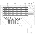
- FIG. 1 is a plan view showing a configuration of a light emitting device 10 according to the first embodiment.
- 2 is a cross-sectional view taken along line AA in FIG. 1
- FIG. 3 is a cross-sectional view taken along line CC in FIG. 1
- FIG. 4 is a cross-sectional view taken along line BB in FIG.
- FIG. 5 is a diagram for explaining the positional relationship among the first electrode 110, the extraction wiring 130, the second electrode 150, and the extraction wiring 160.
- the light-emitting device 10 is a display is illustrated.
- the light emitting device 10 includes a structure on one surface side of the substrate 100. In the example shown in this drawing, this structure extends on one surface side of the substrate 100.
- this structure is a partition wall 170, and a plurality of structures are provided on the substrate 100.
- An organic layer 140 is formed between the partition walls 170.
- the organic layer 140 is formed in a line shape.
- the partition wall 170 divides the second electrode 150 formed on the organic layer 140.
- the second electrode 150 is formed in a line shape by the partition wall 170.
- the light emitting device 10 described above may be a lighting device or a lighting device that can achieve color rendering.
- the light emitting device 10 includes a substrate 100, an organic EL element, an insulating layer 120, a partition 170, a plurality of first openings 122, a plurality of second openings 124, and a plurality of lead wires 160.
- the organic EL element is composed of a laminate in which the first electrode 110, the organic layer 140, and the second electrode 150 are stacked in this order. This organic EL element is located between the plurality of partition walls 170. That is, the organic EL element and the lead wiring 160 are located on one surface side of the substrate 100.
- the first electrode 110 is formed on the first surface side of the substrate 100 and extends in a line shape in the first direction (Y direction in FIG. 1).
- the insulating layer 120 is formed on the plurality of first electrodes 110.
- the organic layer 140 is formed on the first electrode 110.
- the second electrode 150 is formed on the organic layer 140 and extends in a second direction (X direction in FIG. 1) intersecting the first direction.
- the second electrode 150 extends in a direction (second direction to be described later) intersecting the first direction in which the plurality of first electrodes 110 extend in a plan view.
- FIGS. 1 the first electrode 110 is formed on the first surface side of the substrate 100 and extends in a line shape in the first direction (Y direction in FIG. 1).
- the insulating layer 120 is formed on the plurality of first electrodes 110.
- the organic layer 140 is formed on the first electrode 110.
- the second electrode 150 is formed on the organic layer 140 and extends in a second direction (X direction in FIG. 1) intersecting the first direction.
- the partition wall 170 is formed on a base (the insulating layer 120 in the example shown in this figure), and between the adjacent second electrodes 150 in the second direction as shown in FIG. It extends in the (X direction in FIG. 1).
- a first opening 122 is formed in the insulating layer 120 and is located at the intersection of the first electrode 110 and the second electrode 150 in plan view as shown in FIG.
- the second opening 124 is formed in the insulating layer 120 and is located at one end of each of the plurality of second electrodes 150 in plan view. Note that the insulating layer 120 having the first opening 122 and the insulating layer 120 having the second opening 124 may be formed of the same material or different materials.
- the insulating layer 120 having the second opening 124 may be formed on the outer peripheral side of the substrate 100 with respect to the insulating layer 120 having the first opening 122.
- the insulating layer 120 having the first opening 122 and the insulating layer 120 having the second opening 124 may be continuous layers or separated layers (separated).
- the organic layer 140 is sandwiched between the first electrode 110 and the second electrode 150 and has a light emitting layer 144.
- a portion of the lead-out wiring 160 on one end side is in the second opening 124 and is connected to the second electrode 150. Further, the portion of the lead-out wiring 160 on the other end side extends to the outer peripheral portion of the substrate 100 and is connected to a terminal for external connection.
- the light emitting device 10 will be described in detail.
- the substrate 100 is formed of, for example, glass or a resin material, but may be formed of other materials.
- the first electrode 110 is a transparent electrode formed of an inorganic material such as ITO (IndiumITOThin Oxide) or IZO (Indium Zinc Oxide), or a conductive polymer such as a polythiophene derivative.
- the first electrode 110 may be a metal thin film that is thin enough to transmit light. In the example shown in the figure, the first electrode 110 extends linearly in the Y direction in the figure. The end of the first electrode 110 is connected to the lead wiring 130.
- the lead-out wiring 130 is a wiring that connects the first electrode 110 and a terminal for external connection.
- the lead wire 130 is a metal wire made of a metal material or an alloy such as ITO, IZO, Al, Cr, or Ag, which is an oxidized conductive material, but is a wire formed of a conductive material other than metal. There may be.
- an extraction wiring 132 and a extraction wiring 130 formed of a material constituting the first electrode 110 that is electrically connected to the first electrode 110 are sequentially arranged. Is formed.
- the lead wires 130 and 132 are formed up to the vicinity of the first opening 122.
- the first electrode 110 is covered with an insulating film, but at least a part of the lead wiring 130 and the lead wiring 132 that are electrically connected to the first electrode 110 may be covered.
- the insulating layer 120 is a photosensitive resin such as a polyimide resin, and is formed in a desired pattern by exposure and development.
- a photosensitive resin such as a polyimide resin
- As the insulating layer 120 for example, a positive photosensitive resin is used.
- the insulating layer 120 may be a resin other than a polyimide resin, for example, an epoxy resin or an acrylic resin.
- the insulating layer 120 has the first opening 122 and the second opening 124 formed therein.
- the first opening 122 is located on the first electrode 110.
- the plurality of first openings 122 are provided at a predetermined interval.
- the plurality of first openings 122 are formed side by side in the direction in which the first electrode 110 extends, and are formed side by side in the direction in which the second electrode 150 extends. For this reason, the plurality of first openings 122 are arranged to form a matrix.
- An organic layer 140 is formed in the first opening 122.
- the organic layer 140 is formed by stacking a hole injection layer 142, a light emitting layer 144, and an electron injection layer 146. Note that part of the organic layers refers to a hole injection layer 142, a light emitting layer 144, an electron injection layer 146, a hole transport layer, or an electron transport layer described later.
- the hole injection layer 142 is in contact with the first electrode 110, and the electron injection layer 146 is in contact with the second electrode 150. In this way, the organic layer 140 is sandwiched between the first electrode 110 and the second electrode 150.
- a hole transport layer may be formed between the hole injection layer 142 and the light-emitting layer 144, and an electron transport layer may be formed between the light-emitting layer 144 and the electron injection layer 146.
- the hole injection layer 142 is formed using a coating method such as an inkjet method.
- at least one of the hole transport layer, the light-emitting layer 144, the electron transport layer, and the electron injection layer 146 may be formed by an inkjet method.
- each layer constituting the organic layer 140 is continuously formed even if it is continuously formed between the adjacent first openings 122 in the direction in which the partition 170 extends. It doesn't have to be. However, as shown in FIG. 4, the organic layer 140 is not formed around the second opening 124.
- the second openings 124 are arranged along one side of the matrix formed by the first openings 122. In other words, the second openings 124 are arranged in the direction of the plurality of first openings 122 arranged side by side along the partition wall 170. When viewed in a direction along one side (for example, the Y direction in FIG. 1), the second openings 124 are arranged at a predetermined interval in the direction along the first electrode 110. In the second opening 124, there is a lead wiring 160 or a part of the lead wiring 160.
- the lead wires 160 and 162 are formed in a region of the first surface of the substrate 100 where the first electrode 110 and the lead wires 130 and 132 are not formed.
- the present invention is not limited to this, and a part of the lead wiring 160 may be formed in a region where the lead wiring 130 is formed.
- a part of the lead wiring 132 may be formed even in a region where the lead wiring 162 is formed.
- the lead wiring 160 may be formed simultaneously with the lead wiring 130, for example, or the lead wiring 160 and the lead wiring 130 may be formed separately.
- the lead wiring 162 may be formed simultaneously with the lead wiring 132, for example, or the lead wiring 162 and the lead wiring 132 may be formed separately.
- the lead wiring 160 is formed on the lead wiring 162.
- the lead-out wiring 162 is formed of the same kind or different material as the material constituting the first electrode 110.
- ITO which is an oxidized conductive material
- ITO or an oxidized conductive material such as IZO having a composition different from that of the ITO constituting the first electrode 110 is used.
- Examples of different materials include metal materials such as Al.
- the lead-out wiring 162 is formed along the lead-out wiring 160, and the lead-out wiring 162 and the lead-out wiring 160 overlap each other. In the illustrated example, the width of the lead-out wiring 162 is larger than the width of the lead-out wiring 160, but the width is not limited to this and may be small.
- a part of the lead-out wiring 160 on one end side is covered with the insulating layer 120 and exposed through the second opening 124.
- a part of the lead wiring 160 on the other end side is led to the outside of the insulating layer 120. That is, the other end side of the lead wiring 160 is exposed to the insulating layer 120.
- the lead wiring 160 extends in a direction substantially orthogonal to the lead wiring 130.
- the second electrode 150 is connected to the lead wiring 160.
- the second electrode 150 is, for example, a metal layer formed of a metal material such as Ag or Al, or a layer formed of an oxidized conductive material such as IZO, and is formed in a direction orthogonal to the first electrode 110 in plan view. Yes.
- One second electrode 150 passes over the plurality of first openings 122.
- the second electrode 150 is connected to the lead wiring 160.
- the end of the second electrode 150 is positioned on the second opening 124, whereby the second electrode 150 and the extraction wiring 160 are connected in the second opening 124.
- a partition wall 170 is formed between the adjacent second electrodes 150.
- the partition 170 is, for example, a photosensitive resin such as a polyimide resin, and is formed in a desired pattern by being exposed and developed.
- the partition wall 170 is formed using, for example, a negative photosensitive resin.
- the partition wall 170 may be made of a resin other than a polyimide resin, for example, an inorganic material such as an epoxy resin, an acrylic resin, or silicon dioxide.
- the partition wall 170 has a trapezoidal cross-sectional shape (reverse trapezoidal shape). That is, the width of the upper surface of the partition wall 170 is larger than the width of the lower surface of the partition wall 170. For this reason, by forming the partition 170 before the second electrode 150, the plurality of second electrodes 150 can be collectively formed by using an evaporation method or a sputtering method. In the case where the plurality of second electrodes 150 are collectively formed, a conductive layer that becomes the second electrode 150 is not formed at least below the partition wall 170. For this reason, the adjacent 2nd electrode 150 can be parted by the partition 170.
- the second electrode 150 can be patterned into a free shape such as a stripe shape, a dot shape, an icon shape, or a curve. Note that a conductive layer similar to the second electrode 150 is formed on the partition wall 170.
- the partition wall 170 may have a function of preventing the coating materials constituting the organic layer 140 located under the adjacent second electrode 150 from being connected to each other. In this case, the partition wall 170 is formed before the organic layer 140.
- a conductive layer to be the first electrode 110 is formed on the substrate 100, and this conductive layer is selectively removed using etching (for example, dry etching or wet etching). Thereby, the first electrode 110 and the lead-out wiring 162 are formed on the substrate 100.
- etching for example, dry etching or wet etching
- a conductive layer to be the lead wirings 130 and 160 is formed on the substrate 100, the first electrode 110, and the lead wiring 162, and the conductive layer is etched (for example, dry etching or wet etching). Selectively remove. Thereby, the lead wires 130 and 160 are formed.
- an insulating layer is formed on the substrate 100, the first electrode 110, and the lead wires 130 and 160, and this insulating layer is selectively removed using etching (for example, dry etching or wet etching). Thereby, the insulating layer 120, the first opening 122, and the second opening 124 are formed.
- etching for example, dry etching or wet etching
- a partition wall 170 is formed on the insulating layer 120, and the partition wall 170 is selectively removed using etching (for example, dry etching or wet etching). Thereby, the partition 170 is formed.
- etching for example, dry etching or wet etching.
- the cross-sectional shape of the partition 170 can be changed to an inverted trapezoid by adjusting the conditions during exposure and development.
- the partition wall 170 is a negative resist
- the portion of the negative resist irradiated with the irradiation light from the exposure light source is cured.
- the partition 170 is formed by dissolving and removing the uncured portion of the negative resist with a developer. In these steps, by adjusting the light irradiation angle from the exposure light source, the position of the mask, the number of exposure light sources, the number of exposures, and the like, the angle of the inverted trapezoid in the cross-sectional shape of the partition wall 170 and the position of the recess 171 to be described later And the size can be adjusted.
- a light emitting device substrate as shown in FIG. 6 is formed.
- This substrate has a configuration in which the organic layer 140 and the second electrode 150 are removed from the light emitting device 10.
- the hole injection layer 142, the light emitting layer 144, and the electron injection layer 146 are formed in this order in the first opening 122.
- at least the hole injection layer 142 is formed using a coating method such as spray coating, dispenser coating, ink jetting, or printing.
- the coating material enters the first opening 122, and the coating material is dried, whereby the above-described layers are formed.
- a coating material used in the coating method a polymer material, a polymer material containing a low-molecular material, or the like is suitable.
- the coating material for example, a polyalkylthiophene derivative, a polyaniline derivative, triphenylamine, a sol-gel film of an inorganic compound, an organic compound film containing a Lewis acid, a conductive polymer, or the like can be used.
- the remaining layers (for example, the light emitting layer 144 and the electron injection layer 146) of the organic layer 140 are formed by an evaporation method. However, these layers may also be formed using any of the above-described coating methods.
- the second electrode 150 is formed on the organic layer 140 by using, for example, a vapor deposition method or a sputtering method.
- At least one of the layers other than the organic layer 140 is also formed using any of the above-described coating methods. It may be formed.
- FIG. 7 is a plan view for explaining the configuration of the partition wall 170.
- a partition 170 that is an example of a structure has a recess 171 formed in a direction that intersects the direction in which the partition 170 extends.
- the recess 171 overlaps, for example, the first opening 122 in the direction in which the partition wall 170 extends.
- the recess 171 may be further away from the second opening 124 than the first opening 122 (the recess 171 closest to the second opening 124 when a plurality of recesses 171 are formed).
- the partition 170 has a plurality of recesses 171 formed therein.
- the recess 171 is formed on at least one side surface of the partition wall 170. In the direction in which the partition wall 170 extends (X direction in the drawing), the recess 171 is provided at least at a position between the first opening 122 and the second opening 124 that are closest to the second opening 124. Yes.
- the plurality of recesses 171 may be provided at predetermined intervals. Moreover, these recessed parts 171 may be provided in one side surface of the partition 170, the other side surface, or one side surface and the other side surface. In addition to the position between the first opening 122 and the second opening 124 that are closest to the second opening 124, a plurality of recesses 171 are formed from one end of the partition wall 170 to the other end. It does not matter. Further, the recess 171 is formed from the middle of the partition wall 170 to one end or the other end other than the position between the first opening 122 and the second opening 124 that are closest to the second opening 124. It does not matter.
- the width of the recess 171 is smaller than the width of the first opening 122 in the direction in which the partition 170 extends (X direction in the figure). That is, the width of the recess 171 is smaller than the width of the organic EL element.
- the width of the recess 171 is not limited to this, and may be larger than the width of the first opening 122.
- the recess 171 is formed on the two side surfaces of the partition wall 170.
- the recess 171 formed on the first side surface which is one side surface and the recess 171 formed on the second side surface which is the other side surface are in the direction in which the partition wall 170 extends.
- the concave portion 171 (first concave portion 171) formed on the first side surface and the concave portion 171 (second concave portion 171) formed on the second side surface are at different positions. There is no overlap. Therefore, a recess 171 is formed in each of the two partition walls 170 disposed on both sides of the first opening 122 at a position overlapping the first opening 122 in the direction in which the partition wall 170 extends.
- the recesses 171 of the plurality of partition walls 170 are formed at the same position in the direction in which the partition walls 170 extend. 8 may be formed at different positions as shown in FIG. Further, in the example of FIG. 8, a plurality of recesses 171 are formed between the first opening 122 and the second opening 124 that are closest to the second opening 124. 171 may be formed.
- FIG. 9 is an enlarged view of a part of the partition wall 170 shown in FIG.
- the recess 171 is formed on the first side surface and the second side surface of the partition wall 170.
- wall 170 extends the length of the recess 171 and L 1, a first recess 171 formed in the side surface of the (first recess 171) and a recess 171 formed in the second side surface (the L 2 / L 1 ⁇ 1, where L 2 is the length of the partition wall 170 between the two recesses 171).
- the distance between the first concave portion 171 and the second concave portion 171 located next to the first concave portion 171 is equal to or larger than the width of the concave portion 171. Is preferred. In this manner, the partition wall 170 can be prevented from falling even if the recess 171 is provided.
- the cross-sectional shape of the partition 170 is an inverted trapezoid.
- the depth d of the concave portion 171 formed on the first side surface and the depth d of the concave portion 171 formed on the second side surface may be substantially equal to each other. However, the depth d may be different from each other on the first side surface or the second side surface. Further, the width of the partition wall 170 at the position of the recess 171 may be smaller than the width of the partition wall 170 in the portion where the recess 171 is not provided.
- the organic layer 140 for example, the hole injection layer 142
- the organic that protrudes from the first opening 122 that is, the region where the organic EL element is formed.
- the coating material that becomes the layer 140 may come into contact with the first side surface or the second side surface of the partition wall 170, spread in the extending direction of the partition wall 170, and reach the second opening 124.
- the partition 170 includes at least a first opening 122 located closest to the second opening 124 in the direction in which the partition 170 extends (X direction in the drawing) and the second opening 124.
- a recess 171 is provided at a position therebetween. Therefore, even if the coating material that becomes the organic layer 140 from the first opening 122 contacts the first side surface or the second side surface of the partition wall 170 and wets and spreads in the extending direction of the partition wall 170, the coating material is It enters the recess 171. For this reason, it can suppress that the coating material used as the organic layer 140 reaches
- the end portion of the coating material constituting the organic layer 140 is located closer to the first opening 122 than the second opening 124.
- the concave portions 171 are formed on both of the two side surfaces of the partition wall 170, it is possible to further prevent the coating material from reaching the second opening 124.
- the width of the recess 171 is smaller than the width of the first opening 122 in the direction in which the partition wall 170 extends. At least one recess 171 is disposed adjacent to the first opening 122. For this reason, even if the coating material that becomes the organic layer 140 overflows from the first opening 122, the overflowing coating material can be prevented from reaching the adjacent first opening 122. As a result, it is possible to further suppress the end portion of the organic layer 140 from reaching the second opening 124.
- the cross-sectional shape of the partition wall 170 at the position of the recess 171 is an inverted trapezoid. Therefore, the coating material that becomes the organic layer 140 that has entered the recess 171 is likely to accumulate between the side surface of the partition wall 170 and the surface of the insulating layer 120. Accordingly, it is possible to further suppress the organic layer 140 from reaching the second opening 124.
- FIG. 10 is a cross-sectional view illustrating a configuration of the partition wall 170 included in the light emitting device 10 according to the second embodiment.
- FIG. 11 is a diagram showing the DD cross section of FIG. 10 together with the insulating layer 120, the first opening 122, and the second opening 124.
- FIG. 12 is a view showing the EE cross section of FIG. 10 together with the insulating layer 120, the first opening 122, and the second opening 124.
- the light emitting device 10 according to the present embodiment has the same configuration as that of the light emitting device 10 according to the first embodiment except for the configuration of the partition wall 170.
- the partition wall 170 has a concave portion in the lower portion (that is, the substrate 100 side).
- a through hole 172 is shown as a recess. That is, a through hole 172 is formed at the boundary between the partition wall 170 and the insulating layer 120.
- the through-hole 172 penetrates the partition wall 170 in a direction intersecting with the direction in which the partition wall 170 extends.
- the through-hole 172 that is a recess is formed from the first side surface to the second side surface of the partition wall 170.
- the through hole 172 penetrates the partition wall 170 in a direction substantially perpendicular to the partition wall 170 (Y direction in the figure).
- the through hole 172 is adjacent to the first opening 122.
- the through hole 172 is provided at a position overlapping the first opening 122 in the extending direction of the partition wall 170.
- no other structure such as wiring is formed inside the through-hole 172, but the present invention is not limited to this, and the coating material constituting the organic layer 140 is present in the through-hole 172. It doesn't matter.
- the through hole 172 may not be adjacent to the first opening 122.
- the through hole 172 may be provided at a position between the adjacent first openings 122 in the extending direction of the partition wall 170.
- a shape (concave portion) that is recessed inward from the side surface of the partition wall 170 may be provided.
- the width of a portion of the partition wall 170 located between adjacent through holes 172 is L 3 and the width of the through hole 172 is L 4 , it is preferable that L 4 / L 3 ⁇ 1. That is, in the extending direction of the partition wall 170, the distance between the through hole 172 and the through hole 172 located adjacent to the through hole 172 is equal to the width of the through hole 172 in the extending direction of the partition wall 170. Smaller is preferred.
- L 4 / L 3 ⁇ 1 the width of the through hole 172 can be made larger than the width of the first opening 122, and the thickness of the organic layer 140 can be made uniform.
- the through-hole 172 in the partition wall 170 it is possible to suppress variation in the thickness of the organic layer 140 in each first opening 122. Moreover, even if the through-hole 172 is provided, the partition wall 170 can be prevented from falling.
- the height of the through hole 172 is, for example, half or less of the height of the partition wall 170.
- the height of the through hole 172 is not limited to this.
- L 3 is formed larger than the interval G between the two adjacent first openings 122 in the direction in which the partition wall 170 extends.
- L 3 is not limited to this, but may be smaller than the distance G.
- the through hole 172 is formed, for example, by relatively reducing the width of the portion of the partition wall 170 where the through hole 172 is to be formed.
- a method of narrowing a part of the partition 170 for example, there is a method of changing an opening pattern of a mask.
- the through hole 172 may be formed using other methods.
- adjusting the exposure time and light intensity of the exposure light source can be mentioned. Specifically, the exposure is performed in two portions on the negative resist portion where the through hole 172 is not formed and the negative resist portion where the through hole 172 is formed.
- the exposure time is set to be short or the light intensity is set to be low for the negative resist portion where the through-hole 172 is formed.
- the exposure time is increased or the light intensity is increased as compared with the negative resist portion where the through hole 172 is formed.
- the manufacturing method of the light emitting device 10 according to the present embodiment is the same as the method shown in the first embodiment except for this point.
- the through-hole 172 is formed in the partition wall 170.
- the thickness of the organic layer 140 in the first opening 122 can be made uniform.
- variation in the thickness of the organic layer 140 in the plurality of first openings 122 can be suppressed.
- the organic layer 140 becomes thicker near the partition wall 170, and the film thickness uniformity of the organic layer 140 in the first opening 122 serving as the organic EL element is increased. Decreases.
- a quality defect such as a difference in the emission color on the central side and the emission color on the outer peripheral side occurs in the organic EL element. In this embodiment, such a phenomenon can be suppressed.
- the coating material for forming any layer of the organic layer 140 protrudes from the first opening 122 and reaches the side surface of the partition wall 170
- the coating material is applied to the side surface of the partition wall 170. Crawling up at least the lower end. For this reason, the angle of the side surface of the partition wall 170 approaches a forward taper.
- the adjacent second electrode 150 may not be divided by the partition 170.
- the partition 170 is provided with the through hole 172, at least a part of the coating material that becomes the organic layer 140 protruding from the first opening 122 enters the through hole 172, and as a result. 32 and FIG.
- the angle of the side surface of the partition wall 170 does not approach a forward taper. Moreover, it can suppress that the organic layer 140 becomes thick too much.
- 32 corresponds to the cross-sectional view of FIG. 10, and
- FIG. 33 corresponds to the FF cross section of FIG.
- the organic layer 140 flows out to the adjacent region through the through hole 172. For this reason, it can suppress that a part of organic layer 140 crawls up the side surface of the partition 170, and the uniformity of the thickness of the organic layer 140 falls.
- at least one layer of the two organic layers 140 adjacent to each other via the partition wall 170 may be connected to each other via the through hole 172.
- the first electrode 110 may be formed on the insulating layer 120 using a coating method after the insulating layer 120 and the partition 170 are formed.
- the coating material to be the first electrode 110 wets and spreads on the surface of the insulating layer 120 constituting the first opening 122 through the through hole 172.
- the first electrode 110 can be formed to have a uniform thickness in the first opening 122, and light emission unevenness can be suppressed. Further, variation in the thickness of the first electrode 110 in the plurality of first openings 122 can be suppressed.
- FIG. 13 is a plan view illustrating a configuration of a main part of the light emitting device 10 according to the third embodiment, and corresponds to FIG. 11 in the second embodiment.
- the light emitting device 10 according to the present embodiment has the same configuration as that of the light emitting device 10 according to the second embodiment, except that a recess 171 is provided instead of the through hole 172.
- the recess 171 according to the present embodiment is not provided in the entire partition 170 when viewed in the height direction, and is provided at least in the lower part, except for the recess 171 according to the first embodiment. It is the same composition as.
- the recess 171 is formed on either of the two side surfaces of the partition wall 170 as in the first embodiment.
- the positions of the recess 171 formed on the first side surface and the recess 171 formed on the second side surface are at least substantially the same in the direction in which the partition wall 170 extends.
- these recesses 171 may be staggered.
- the distance L 5 between two recesses 171 adjacent in the direction wall 170 extends, are formed small with respect to the spacing G of the two first openings 122 adjacent. Thereby, the thickness of the organic layer 140 in the first opening 122 can be made uniform. Further, variation in the thickness of the first electrode 110 in the plurality of first openings 122 can be suppressed.
- the side surface of the partition wall 170 is not crawled. For this reason, it can suppress that the angle of the side surface of the partition 170 approaches a forward taper, and the 2nd electrode 150 can be parted by the partition 170.
- FIG. 14 is a cross-sectional view illustrating a configuration of the insulating layer 120 and the partition 170 included in the light emitting device 10 according to the fourth embodiment.
- FIG. 15 is a plan view showing the partition wall 170 and the surrounding structure.
- the light emitting device 10 according to the present embodiment is the same as the third embodiment except that the partition wall 170 has neither the through-hole 172 nor the recess 171, but a recess 126 is formed at least on the insulating layer 120.
- the configuration is the same as that of the light emitting device 10 according to the embodiment.
- a plurality of the recesses 126 are formed for one partition 170.
- the arrangement and width of the recesses 126 in the direction in which the partition 170 extends are the same as the arrangement of the recesses 171 in the third embodiment.
- the recess 126 when viewed in the width direction of the partition wall 170, is formed so as to include a region overlapping the lower end of the side surface of the partition wall 170 in plan view. That is, in a plan view, each of the plurality of recesses 126 is partially located outside the partition wall 170 and partially overlaps the partition wall 170.
- the recess 126 does not penetrate the insulating layer 120 in the thickness direction. However, as shown in FIG. 16, the recess 126 may penetrate the insulating layer 120 in the thickness direction.
- the recess 126 is formed, for example, in the same process as the first opening 122 and the second opening 124.
- the recess 126 may be formed by devising the exposure condition of the insulating layer 120. For example, the irradiation angle of the exposure light, the position of the opening of the exposure mask, the number of exposure light sources, the number of exposures can be adjusted, and the position, number, shape of the recess, and depth can be adjusted.
- the recess 126 may be formed by etching the insulating layer 120 as described above.
- the present embodiment it is possible to suppress variation in the thickness of the organic layer 140 in each first opening 122, and it is possible to suppress the occurrence of light emission unevenness. Moreover, when the insides of the plurality of first openings 122 are compared, variation in the thickness of the organic layer 140 can be suppressed. Moreover, when the 1st electrode 110 is formed with a coating material, it can suppress that the thickness of the 1st electrode 110 varies. Further, as shown in the cross-sectional view of FIG. 34, at least a part of the coating material of the organic layer 140 that protrudes from the first opening 122 enters the recess 126 and is then dammed by the lower surface of the partition wall 170. It becomes difficult to scoop up the side. For this reason, it can suppress that the angle of the side surface of the partition 170 approaches a trapezoid shape (forward taper) from an inverted trapezoid shape similarly to 3rd Embodiment.
- a trapezoid shape forward taper
- FIG. 17 is a cross-sectional view illustrating the configuration of the insulating layer 120 and the partition 170 included in the light emitting device 10 according to the fifth embodiment.
- the light emitting device 10 according to the present embodiment has the same configuration as that of the light emitting device 10 according to the fourth embodiment, except that the recess 126 passes through a portion overlapping the partition wall 170 in plan view.
- the recess 126 may be formed as a recess having the same thickness as the insulating layer 120 in the depth direction.
- the present embodiment similarly to the fourth embodiment, it is possible to suppress the variation in the thickness of the organic layer 140 in each first opening 122, and it is possible to suppress the occurrence of light emission unevenness. Moreover, when the insides of the plurality of first openings 122 are compared, variation in the thickness of the organic layer 140 can be suppressed. Moreover, when the 1st electrode 110 is formed with a coating material, it can suppress that the thickness of the 1st electrode 110 varies. Moreover, it can suppress that the angle of the side surface of the partition 170 approaches trapezoid shape (forward taper) from an inverted trapezoid shape. Moreover, since the recessed part 126 has penetrated the partition 170 in the width direction, the capacity
- FIG. 19 is a cross-sectional view illustrating configurations of the substrate 100, the insulating layer 120, and the partition wall 170 included in the light emitting device 10 according to the sixth embodiment.
- the light emitting device 10 according to the present embodiment has the same configuration as the light emitting device 10 according to the fifth embodiment except for the following points.
- a recess 102 is formed in a region of the first surface of the substrate 100 that overlaps the recess 126. For this reason, when forming the insulating layer 120, the recess 126 can be formed along the recess 102. Therefore, according to the present embodiment as well as the fifth embodiment, it is possible to suppress the variation in the thickness of the organic layer 140 in each first opening 122 and to prevent the occurrence of uneven light emission. Moreover, when the insides of the plurality of first openings 122 are compared, variation in the thickness of the organic layer 140 can be suppressed. Moreover, when the 1st electrode 110 is formed with a coating material, it can suppress that the thickness of the 1st electrode 110 varies. Further, it is possible to sufficiently suppress the coating material of the organic layer 140 from climbing up the side wall of the partition wall 170.
- FIG. 20 is a plan view showing the configuration of the light emitting device 10 according to the seventh embodiment. This figure shows a case corresponding to the DD cross section in FIG. 10 and the through hole 172 between the first opening 122 and the second opening 124 closest to the lead-out wiring 160.
- the light emitting device 10 according to the present embodiment includes at least a through hole between the second opening 124 and the first opening 122 located closest to the first opening 122 side, for example, the second opening 124 from the lead-out wiring 160.
- the configuration is the same as that of the light-emitting device 10 according to the second embodiment except that 172 is included.
- the through hole 172 is positioned between the organic EL element closest to one end portion of the extraction wiring 160 and one end portion of the extraction wiring 160 or the second opening 124. is doing.
- the configuration of the through hole 172 is the same as the configuration of the through hole 172 according to the second embodiment except for the arrangement position.
- the through hole 172 is provided at a position different from the position of the first opening 122 and the position of the second opening 124 in the direction in which the partition wall 170 extends.
- the present invention is not limited to this, and at least a part of the through hole 172 may be at least one of the position of the first opening 122 and the position of the second opening 124.
- the partition wall 170 may have at least one through-hole 172 at a position different from the position of the first opening 122 in the extending direction of the partition wall 170 as in the second embodiment.
- the through hole 172 may be formed at a position between the adjacent first openings 122 in the extending direction of the partition wall 170.
- the coating material forming the organic layer 140 that protrudes from the first opening 122 spreads wet along the side wall of the partition wall 170 toward the second opening 124, the coating material is passed through the through-hole 172. Can be poured into.
- the flow of the coating material of the organic layer 140 can be blocked by a portion of the inner wall of the through hole 172 located near the second opening 124. Therefore, this coating material can be prevented from reaching the second opening 124.
- the coating material reaches the second opening 124 as described above even if the concave portion 171 having the same configuration as that of the third embodiment is provided instead of the through-hole 172. This can be suppressed.
- the coating material as described above can be used as the second coating material. Reaching the opening 124 can be suppressed.
- FIG. 23 is a plan view showing the partition wall 170 and its surrounding structure in the light emitting device 10 according to the eighth embodiment.
- the light emitting device 10 according to the present embodiment has the same configuration as the light emitting device 10 according to the first embodiment, except for the structure of the partition wall 170.
- the cross-sectional shape of the partition 170 that is, the size of the partition 170 is larger than the first opening 122 located closest to the second opening 124 in the direction in which the partition 170 extends. Or different in shape.
- a wall surface 175 is provided at the boundary.
- the partition wall 170 has a first partition wall portion 174 located on the first opening 122 side and a second partition wall portion 176 located on the second opening 124 side with the wall surface 175 as a boundary. Yes.
- the width of the lower surface of the first partition wall portion 174 is smaller than the width of the lower surface of the second partition wall portion 176.
- the width of the lower surface of the first partition wall 174 in contact with the insulating layer 120 is smaller than the width of the lower surface of the second partition wall 176 in contact with the insulating layer 120.
- the width of the first partition in the extending direction of the partition 170 is at least longer than the first opening 122.
- variety of an upper surface is larger than the width
- the cross-sectional shape is an inverted trapezoid. For this reason, when forming the 2nd electrode 150 grade
- the cross-sectional shape of the first partition wall 174 is different from the cross-sectional shape of the second partition wall 176.
- the width of a part of the second partition wall part 176 connected to the insulating layer 120 in the direction intersecting the extending direction of the partition wall 170 is the same as the width of a part of the first partition wall part 174 connected to the insulating layer 120.
- it is formed large.
- the adhesive strength of the partition 170 with respect to the insulating layer 120 improves, and it can suppress that the partition 170 falls down.
- the coating material of the organic layer 140 protruding from the first opening 122 can be prevented from touching the side wall of the first partition wall portion 174.
- the first partition wall portion 174 is narrower than the second partition wall portion 176 in the width of the portion in contact with the insulating layer 120. For this reason, it can suppress that the coating material of the organic layer 140 which protruded from the 1st opening 122 touches the side surface of the 1st partition part 174.
- FIG. When the coating material of the organic layer 140 comes into contact with the partition 170, the organic layer 140 becomes thicker near the partition 170. In the present embodiment, such a phenomenon can be suppressed, and the uniformity of the thickness of the organic layer 140 in the portion that becomes the organic EL element can be improved.
- the width of the lower end portion of the first partition wall portion 174 that is, the width of the portion connected to the insulating layer 120 is narrower than the width of the lower end portion of the second partition wall portion 176. That is, the portion where the first partition wall 174 is in contact with the insulating layer 120 is relatively small. Therefore, even if at least a part of the organic layer 140 touches the side wall of the first partition wall portion 174, as shown in the cross-sectional view of FIG.
- the second electrode 150 can be divided. Moreover, it can suppress that the coating material of the organic layer 140 is pulled by the side surface of the 1st partition part 174. FIG. Therefore, the uniformity of the film thickness of the organic layer 140 can be improved.
- the coating material of the organic layer 140 protruding from the first opening 122 can be prevented from touching the side surface of the first partition wall 174, the coating material of the organic layer 140 enters the second opening 124 along the side wall of the partition wall 170. It is also possible to suppress spreading wet.
- the coating material of the organic layer 140 can be blocked by the wall surface 175. Therefore, the coating material for the organic layer 140 can be prevented from reaching the second opening 124.
- the width of the lower surface of the first partition wall portion 174 is narrower than the width of the lower surface of the second partition wall portion 176, the side surface of the first partition wall portion 174 and the connection portion of the wall surface 175 form a corner. is doing. In this case, the coating material of the organic layer 140 can be easily damped at the corners.
- the width of the portion where the first partition 174 and the insulating layer 120 are in contact with each other may be substantially zero.
- the lower end of the first partition wall 174 may be separated from the base (in the example shown in this figure, the insulating layer 120.
- the extending direction of the partition 170 in FIG. As shown in the cross-sectional view (that is, the GG cross-sectional view in FIG. 37), the second partition 176 is provided at both ends of the first partition 174.
- the lower end of the first partition 174 is It will be located above the lower end of the two partition walls 176.
- the first partition walls 174 are supported by the second partition walls 176 at both ends.
- the cross section of the first partition wall 174 may have a curved shape in which the side corresponding to the side surface is recessed inward. Also in this case, as shown in the cross-sectional view of FIG. 36, even if at least a part of the organic layer 140 touches the side wall of the first partition wall 174, the cross-sectional shape of the first partition wall 174 is inverted trapezoidal.
- the second electrode 150 can be divided.
- the first partition 174 and the second partition 176 are connected. However, the first partition 174 and the second partition 176 may be separated. In this case, a space is provided between the first partition wall portion 174 and the second partition wall portion 176. Further, the first partition 174 and the second partition 176 may be formed of the same material and in the same process, but the first partition 174 and the second partition 176 may be formed of separate processes. . In this case, the first partition 174 and the second partition 176 may be formed of different materials.
- FIG. 26 is a plan view showing the partition wall 170 and the surrounding structure in the light emitting device 10 according to the ninth embodiment. This figure corresponds to the DD section of FIG.
- the light emitting device 10 according to the present embodiment has the same configuration as that of the light emitting device 10 according to the eighth embodiment, except that the partition wall 170 has a through hole 172.
- the position of the through hole 172 is at the position of the first opening 122 in the direction in which the partition wall 170 extends, and the width of the through hole 172 in the extending direction of the partition wall 170 is smaller than the width of the first opening 122.
- the through hole 172 is formed below the first partition wall 174, that is, at the boundary between the insulating layer 120 and the first partition wall 174.
- the uniformity of the thickness of the organic layer 140 in the portion to be the organic EL element can be improved.
- the cross-sectional shape of the first partition wall 174 can be maintained in an inverted trapezoidal shape, and the second electrode 150 can be divided. Further, it is possible to prevent the coating material of the organic layer 140 from spreading along the side wall of the partition wall 170 toward the second opening 124. In addition, the coating material of the organic layer 140 can be blocked by the wall surface 175. Further, since the through hole 172 is provided, the uniformity of the thickness of the organic layer 140 in the portion to be the organic EL element can be improved as in the second embodiment.
- the length of the portion of the first partition 174 that is separated from the insulating layer 120 is smaller than the portion of the second partition 176 that is in contact with the insulating layer 120.
- the partition wall 170 does not fall down.
- the partition wall 170 for example, both the first partition wall portion 174 and the second partition wall portion 176 may have a shape in which a plurality of partition wall portions 178 are stacked in a plurality of stages.
- the plurality of partition walls 178 have an inverted trapezoidal cross section.
- the through-hole 172 may be partially formed in the lower part of the at least one partition part 178 located in the second stage or more by the same method as the partition 170 in the second embodiment. In this case, the through hole 172 can be separated from the upper surface of the insulating layer 120.
- the cross-sectional shape of the first partition wall portion 174 is a shape in which the partition wall portions 178 shown in FIG. 27 are stacked
- the cross-sectional shape of the second partition wall portion 176 is the partition wall 170 as shown in FIG. You can also. Further, the matters described in the above-described embodiment can be combined with this embodiment.
- FIG. 28 is a plan view showing the configuration of the light emitting device 10 according to the example. 29 is a sectional view taken along line AA in FIG. 28, FIG. 30 is a sectional view taken along line CC in FIG. 28, and FIG. 31 is a sectional view taken along line BB in FIG.
- the light emitting device 10 according to this example has the same configuration as that of the light emitting device 10 according to any one of Embodiments 1 to 9, except that the insulating layer 120 is not provided.
- the partition 170 is formed on the substrate 100 and the first electrode 110. That is, in this embodiment, the base of the partition wall 170 is the substrate 100.
- the organic layer 140 is formed in a stripe shape in a region located between the partition walls 170 on the substrate 100 and the first electrode 110. Further, the width of the organic layer 140 is wider than the width of the second electrode 150 in order to prevent the first electrode 110 and the second electrode 150 from being short-circuited. Note that the organic layer 140 may be formed only in a region on the first electrode 110 where the first opening 122 was present. Although the organic layer 140 is formed in a stripe shape, the organic layer 140 may be formed in a dot shape.
- the coating material to be the organic layer 140 can be further prevented from reaching the second opening.
- the cross-sectional shape of the partition wall 170 can be maintained in a reverse taper.
Abstract
第2電極(150)は、絶縁層(120)上に形成されている。第2電極(150)は、平面視で複数の第1電極(110)と交わり、かつ一端が複数の第1電極(110)のいずれとも重なっていない。隔壁(170)は、隣り合う第2電極(150)の間を延在している。第1開口(122)は絶縁層(120)に形成されており、第1電極(110)と第2電極(150)の交点に重なっている。第2開口(124)は絶縁層(120)に形成されており、平面視で複数の第2電極(150)のそれぞれの一端に位置している。隔壁(170)には複数の凹部(171)が形成されている。凹部(171)は、少なくとも一部が、第2開口(124)の最も近くに位置する第1開口(122)と重なっている。
Description
本発明は、発光装置に関する。
照明装置やディスプレイの光源の一つに、有機EL(organic electroluminescence)がある。有機ELをディスプレイとして使用する場合、発光する領域を画素単位で制御する必要がある。このために、例えば特許文献1には、以下の構造が開示されている。
まず、基板上にITO(Indium Tin Oxide)からなる配線状の第1電極を形成する。次いで、この第1電極上に絶縁層を形成する。この絶縁層には、画素となる領域のそれぞれに開口を有している。そして、これらの開口内に有機層を形成する。そして、有機層の上及び絶縁層上に、複数の配線状の第2電極を形成する。この絶縁層上には、第2電極と平行に隔壁が形成されている。隔壁は、隣り合う第2電極の間に位置している。言い換えると、隣り合う隔壁の間には、複数の画素(開口)が一列に並んで配置されている。
有機ELの有機層の形成方法の一つに、インクジェットなどの塗布法がある。画素となる開口内に有機層を塗布すると、有機層が隔壁に沿って濡れ広がる可能性がでてくる。特許文献1では、隔壁に突起を設けることにより、有機層が広がることを抑制できる、と記載されている。
第2電極は、基板上に形成された引出配線に接続されている。この接続方法の一つに、第2電極の端部と重なる位置に引出配線の一部を配置し、ここで引出配線と第2電極を接続させる方法がある。このような構造に対して有機層を塗布法で形成する場合、有機層が隔壁に沿って濡れ広がって引出配線まで達し、第2電極と引出配線との間に接触不良が生じる可能性があった。
また、特許文献1に記載の技術では、隔壁のうち引出配線と重なる領域に突起を設ける必要があるため、引出配線の幅を小さくする必要がある。引出配線の幅が小さくなると、引出配線と第2電極の接触抵抗が大きくなってしまう。
本発明が解決しようとする課題は、有機層が引出配線まで濡れ広がることを抑制すること、引出配線と第2電極の接続抵抗又は配線抵抗が大きくなることを抑制することが一例として挙げられる。
請求項1に記載の発明は、基板と、
前記基板の一面側に位置する有機EL素子と、
前記基板の前記一面側に位置する引出配線と、
前記基板の前記一面側に位置する構造物を備え、
前記構造物は、前記構造物の延在方向に対して交差する方向に凹部を備えることを特徴とする発光装置である。
前記基板の一面側に位置する有機EL素子と、
前記基板の前記一面側に位置する引出配線と、
前記基板の前記一面側に位置する構造物を備え、
前記構造物は、前記構造物の延在方向に対して交差する方向に凹部を備えることを特徴とする発光装置である。
上述した目的、およびその他の目的、特徴および利点は、以下に述べる好適な実施の形態、およびそれに付随する以下の図面によってさらに明らかになる。
以下、本発明の実施の形態について、図面を用いて説明する。尚、すべての図面において、同様な構成要素には同様の符号を付し、適宜説明を省略する。
(第1の実施形態)
図1は、第1の実施形態に係る発光装置10の構成を示す平面図である。図2は図1のA-A断面図であり、図3は図1のC-C断面図であり、図4は図1のB-B断面図である。また、図5は、第1電極110、引出配線130、第2電極150、及び引出配線160の位置関係を説明するための図である。以下の説明では、発光装置10がディスプレイである場合を例示している。発光装置10は、基板100の一面側に構造物を備える。本図に示す例において、この構造物は、基板100の一面側で延在している。例えばこの構造物は隔壁170であり、基板100上に複数設けられている。この隔壁170の間には、有機層140が形成されている。図示の場合、この有機層140は、ライン状に形成されている。隔壁170は、有機層140の上に形成される第2電極150を分断する。図示の例では、隔壁170により、ライン状に第2電極150が形成される。前述した発光装置10は、照明装置、又は演色性を達成できる照明装置であっても構わない。
図1は、第1の実施形態に係る発光装置10の構成を示す平面図である。図2は図1のA-A断面図であり、図3は図1のC-C断面図であり、図4は図1のB-B断面図である。また、図5は、第1電極110、引出配線130、第2電極150、及び引出配線160の位置関係を説明するための図である。以下の説明では、発光装置10がディスプレイである場合を例示している。発光装置10は、基板100の一面側に構造物を備える。本図に示す例において、この構造物は、基板100の一面側で延在している。例えばこの構造物は隔壁170であり、基板100上に複数設けられている。この隔壁170の間には、有機層140が形成されている。図示の場合、この有機層140は、ライン状に形成されている。隔壁170は、有機層140の上に形成される第2電極150を分断する。図示の例では、隔壁170により、ライン状に第2電極150が形成される。前述した発光装置10は、照明装置、又は演色性を達成できる照明装置であっても構わない。
発光装置10は、詳細には、基板100、有機EL素子、絶縁層120、隔壁170、複数の第1開口122、複数の第2開口124、及び複数の引出配線160を有している。そして、有機EL素子は、第1電極110、有機層140、及び第2電極150の順で積層した積層物で構成される。この有機EL素子は、複数の隔壁170の間に位置している。すなわち有機EL素子及び引出配線160は、基板100の一面側に位置している。
第1電極110は、図1及び図5に示すように、基板100の第1面側に形成され、第1方向(図1におけるY方向)にライン状に延在している。絶縁層120は、図1~図4に示すように、複数の第1電極110上に形成されている。有機層140は、第1電極110上に形成される。第2電極150は、図1~図4に示すように、有機層140上に形成され、第1方向と交わる第2方向(図1におけるX方向)に延在している。第2電極150は、図5に示すように、平面視で複数の第1電極110が延在する第1方向に対して交差する方向(後述する第2方向)にて延在している。隔壁170は、図2~図4に示すように、下地(本図に示す例では絶縁層120)上に形成され、図1に示すように、隣り合う第2電極150の間を第2方向(図1におけるX方向)に延在している。絶縁層120には、第1開口122が形成されており、図5に示すように、平面視で第1電極110と第2電極150の交点に位置する。また、第2開口124は絶縁層120に形成されており、平面視で複数の第2電極150のそれぞれの一端に位置している。なお、第1開口122を有する絶縁層120と、第2開口124を有する絶縁層120は同一の材料で形成しても構わなく、異なる材料で形成しても構わない。また、第1開口122を有する絶縁層120に対して基板100の外周部側に、第2開口124を有する絶縁層120を形成しても構わない。また、第1開口122を有する絶縁層120と第2開口124を有する絶縁層120は連続する層であっても構わなく、分離した層(分断している)であって構わない。
有機層140は、第1電極110及び第2電極150に挟持されており、発光層144を有している。平面視において、一端側における引出配線160の部分が第2開口124内にあり、第2電極150に接続している。また他端側における引出配線160の部分は、基板100の外周部まで延在しており、外部接続用の端子に接続されている。以下、発光装置10について詳細に説明する。
基板100は、例えばガラスや樹脂材料で形成されているが、他の材料によって形成されていても良い。
第1電極110は、例えばITO(Indium Thin Oxide)やIZO(インジウム亜鉛酸化物)などの無機材料、またはポリチオフェン誘導体などの導電性高分子によって形成された透明電極である。第1電極110は、光が透過する程度に薄い金属薄膜であっても良い。本図に示す例において、第1電極110は、図中Y方向に直線状に延在している。そして第1電極110の端部は、引出配線130に接続している。
引出配線130は、第1電極110と外部接続用の端子とを接続する配線である。引出配線130は、例えば、酸化導電材料であるITO、IZO、Al、Cr、又はAgなどの金属材料又は合金で構成される金属配線であるが、金属以外の導電性材料によって形成された配線であっても良い。図1及び図5に示す例では、基板100の上には、第1電極110に電気的に接続される第1電極110を構成する材料で形成された引出配線132及び引出配線130の順で形成されている。本図に示す例では、引出配線130,132は第1開口122の近傍まで形成されている。図示の例では、第1電極110が絶縁膜で覆われているが、第1電極110に電気的に接続される引出配線130及び引出配線132の少なくとも一部が覆われていても構わない。
絶縁層120は、ポリイミド系樹脂などの感光性の樹脂であり、露光及び現像されることによって、所望のパターンに形成されている。絶縁層120としては、例えば、ポジ型の感光性樹脂が用いられる。なお、絶縁層120はポリイミド系樹脂以外の樹脂、例えばエポキシ系樹脂やアクリル系樹脂であっても良い。
上記したように、絶縁層120には第1開口122及び第2開口124が形成されている。第1開口122は、第1電極110の上に位置する。また、複数の第1開口122は、所定の間隔を空けて設けられている。そして、複数の第1開口122は、第1電極110が延在する方向にて並べて形成されており、第2電極150の延在方向にて並べて形成されている。このため、複数の第1開口122はマトリクスを構成するように配置されていることになる。
第1開口122の中には、有機層140が形成されている。図2に示す例では、有機層140は、正孔注入層142、発光層144、及び電子注入層146を積層したものである。なお、一部の有機層は、正孔注入層142、発光層144、電子注入層146、後述する正孔輸送層、又は電子輸送層を指す。正孔注入層142は第1電極110に接しており、電子注入層146は第2電極150に接している。このようにして、有機層140は第1電極110と第2電極150の間で挟持されている。なお、正孔注入層142と発光層144の間には正孔輸送層が形成されても良いし、発光層144と電子注入層146の間には電子輸送層が形成されてもよい。いずれの場合においても、正孔注入層142は、インクジェット法などの塗布法を用いて形成されている。また、正孔輸送層、発光層144、電子輸送層、及び電子注入層146の少なくとも一方も、インクジェット法によって形成されていても良い。
なお、図2及び図3に示す例では、有機層140を構成する各層は、いずれも第1開口122の外側まではみ出している場合を示している。そして図3に示すように、有機層140を構成する各層は、隔壁170が延在する方向において、隣り合う第1開口122の間にも連続して形成されていても、連続して形成していなくても構わない。ただし、図4に示すように、有機層140は、第2開口124の周囲には形成されていない。
また第2開口124は、第1開口122が構成するマトリクスの一辺に沿って配置されている。言い換えれば、隔壁170に沿って並べて配置される複数の第1開口122の方向において、第2開口124は配置されている。そしてこの一辺に沿う方向(例えば図1におけるY方向)で見た場合、第2開口124は、第1電極110に沿う方向において、所定の間隔で配置されている。第2開口124には、引出配線160又は引出配線160の一部分がある。
図1の例では、引出配線160、162は、基板100の第1面のうち第1電極110及び引出配線130、132が形成されていない領域に形成されている。これに限らず、引出配線160の一部が引出配線130が形成される領域内にまで形成されていても構わない。同様に、引出配線132の一部が引出配線162が形成される領域内にまで形成されていても構わない。引出配線160は、例えば引出配線130と同時に形成しても構わなく、或いは引出配線160と引出配線130は別々に形成しても構わない。同様に、引出配線162は、例えば引出配線132と同時に形成しても構わなく、或いは引出配線162と引出配線132は別々に形成しても構わない。引出配線160は、引出配線162の上に形成されている。引出配線162は、第1電極110を構成する材料と同種の又は異なる材料で形成されている。ここで同種の材料の例としては、第1電極110が酸化導電材料であるITOで形成されている場合、第1電極110を構成するITOと組成が異なるITO、又はIZOなどの酸化導電材が挙げられる。また異なる材料の例として、Al等の金属材料などが挙げられる。引出配線162は、引出配線160に沿って形成されており、引出配線162と引出配線160は重なっている。図示の例では、この引出配線162の幅は、引出配線160の幅に対して大きくが、これに限定されず幅は小さくとも構わない。
一端側における引出配線160の一部分は、絶縁層120に覆われており、かつ第2開口124にて露出している。また、他端側における引出配線160の一部分は、絶縁層120の外側に引き出されている。すなわち、引出配線160の他端側は、絶縁層120に対して露出している。この他端側における引出配線160の一部分において、引出配線160は引出配線130と略直交する方向に延在している。そして第2開口124において、第2電極150は引出配線160に接続している。
第2電極150は、例えばAgやAlなどの金属材料で形成された金属層、IZOなどの酸化導電材料で形成された層であり、平面視で第1電極110に直交する方向に形成されている。一つの第2電極150は、複数の第1開口122上を通っている。第2電極150は引出配線160に接続している。図示の例では、第2電極150の端部が第2開口124上に位置することにより、第2開口124において第2電極150と引出配線160は接続している。
隣り合う第2電極150の間には、隔壁170が形成されている。隔壁170は、例えばポリイミド系樹脂などの感光性の樹脂であり、露光及び現像されることによって、所望のパターンに形成されている。隔壁170は、例えばネガ型の感光性樹脂を用いて形成される。なお、隔壁170はポリイミド系樹脂以外の樹脂、例えばエポキシ系樹脂やアクリル系樹脂、二酸化珪素等の無機材料で構成されていても良い。
隔壁170は、断面が台形の上下を逆にした形状(逆台形)を有している。すなわち隔壁170の上面の幅は、隔壁170の下面の幅よりも大きい。このため、隔壁170を第2電極150より前に形成しておくことで、複数の第2電極150を蒸着法やスパッタリング法を用いて一括で形成することができる。複数の第2電極150を一括で形成した場合、隔壁170の少なくとも下部には第2電極150となる導電層は形成されない。このため、隣り合う第2電極150を隔壁170により分断することができる。そして隔壁170の延在方向を変えることにより、第2電極150をストライプ形状、ドット形状、アイコン状、曲線などの自由な形状にパターニングできる。なお、隔壁170の上には、第2電極150と同様の導電層が形成されている。
また、隔壁170は、隣り合う第2電極150の下に位置する有機層140を構成する塗布材料が互いに繋がることを防止する機能を有していても構わない。この場合、隔壁170は、有機層140より前に形成されている。
次に、発光装置10の製造方法について説明する。まず基板100上に第1電極110となる導電層を形成し、この導電層をエッチング(例えばドライエッチング又はウェットエッチング)などを利用し、選択的に除去する。これにより、基板100上には、第1電極110及び引出配線162が形成される。
次いで、基板100上、第1電極110上、及び引出配線162上に、引出配線130,160となる導電層を形成し、この導電層をエッチング(例えばドライエッチング又はウェットエッチング)などを利用し、選択的に除去する。これにより、引出配線130,160が形成される。
次いで、基板100上、第1電極110上、及び引出配線130,160上に絶縁層を形成し、この絶縁層をエッチング(例えばドライエッチング又はウェットエッチング)などを利用し、選択的に除去する。これにより、絶縁層120、第1開口122、及び第2開口124が形成される。
次いで、絶縁層120上に隔壁170を形成し、この隔壁170をエッチング(例えばドライエッチング又はウェットエッチング)など利用し、選択的に除去する。これにより、隔壁170が形成される。隔壁170が感光性の絶縁膜で形成される場合、露光及び現像時の条件を調節することにより、隔壁170の断面形状を逆台形にすることができる。
隔壁170がネガ型レジストである場合、このネガ型レジストは、露光光源から照射光が照射された部分が硬化する。そして、このネガ型レジストのうち未硬化部分を現像液で溶解除去することにより、隔壁170が形成される。これらの工程において、露光光源による光の照射角度、マスクの位置、露光光源の数、及び露光回数などを調整することにより、隔壁170の断面形状における逆台形の角度や、後述する凹部171の位置及び大きさを調整することができる。
この段階で、図6に示すような発光装置用基板が形成される。この基板は、発光装置10から有機層140及び第2電極150を除いた構成を有している。
次いで、第1開口122内に正孔注入層142、発光層144、及び電子注入層146を、この順に形成する。これらのうち少なくとも正孔注入層142は、例えばスプレー塗布、ディスペンサー塗布、インクジェット、又は印刷などの塗布法を用いて形成される。この場合、第1開口122内に塗布材料が入り込み、この塗布材料が乾燥することにより、上記した各層が形成される。塗布法で用いられる塗布材料としては、高分子材料、高分子材料中に低分子材料を含んだものなどが適している。塗布材料としては、例えば、ポリアルキルチオフェン誘導体、ポリアニリン誘導体、トリフェニルアミン、無機化合物のゾルゲル膜、ルイス酸を含む有機化合物膜、導電性高分子などを利用することができる。なお、有機層140のうち残りの層(例えば発光層144及び電子注入層146)は、蒸着法により形成される。ただしこれらの層も、上記した塗布法のいずれかを用いて形成されても良い。
その後、有機層140上に第2電極150を、例えば蒸着法やスパッタリング法を用いて形成する。
なお、有機層140以外の層、例えば第1電極110、絶縁層120、引出配線130、引出配線160、第2電極150、及び隔壁170の少なくとも一つも、上記した塗布法のいずれかを用いて形成されても良い。
図7は、隔壁170の構成を説明するための平面図である。本実施形態において、構造物の一例である隔壁170には、隔壁170の延在する方向に対して交差する方向に、凹部171が形成されている。凹部171は、隔壁170が延在する方向において、例えば、第1開口122と重なっている。また凹部171は、第1開口122(複数の凹部171が形成されている場合は第2開口124に最も近い凹部171)よりも第2開口124から離れていてもよい。本図に示す例では、隔壁170には複数の凹部171が形成されている。凹部171は、隔壁170の少なくとも一方の側面に形成されている。隔壁170が延在する方向(図中X方向)において、凹部171は、少なくとも、第2開口124に最も近い位置にある第1開口122と、第2開口124との間の位置に設けられている。
複数の凹部171は、所定の間隔にて設けられていても構わない。また、これら凹部171は、隔壁170の一方の側面、又は他方の側面、又は一方の側面及び他方の側面に設けられていても構わない。また、凹部171は、第2開口124に最も近い位置にある第1開口122と第2開口124との間の位置以外に、隔壁170の一方の端部から他方の端部にかけて、複数形成されていても構わない。また、凹部171は、第2開口124に最も近い位置にある第1開口122と第2開口124との間の位置以外に、隔壁170の中間から一方の端部又は他方の端部にかけて形成されていても構わない。また本図に示す例では、隔壁170が延在する方向(図中X方向)において、凹部171の幅は第1開口122の幅よりも小さく形成されている。すなわち凹部171の幅は、有機EL素子の幅に対して小さくなっている。凹部171の幅は、これに限定されず、第1開口122の幅より大きくても構わない。
本図に示す例では、凹部171は、隔壁170の2つの側面に形成されている。隔壁170の2つの側面のうち、一方の側面である第1の側面に形成された凹部171と、他方の側面である第2の側面に形成された凹部171は、隔壁170が延在する方向において互い違いになっている。すなわち図中X方向において、第1の側面に形成された凹部171(第1の凹部171)と、第2の側面に形成された凹部171(第2の凹部171)は互いに異なる位置にあり、重なっていない。このため、隔壁170が延在する方向において、第1開口122と重なる位置に、第1開口122の両側に配置される2つの隔壁170のそれぞれに凹部171が形成されている。
なお、図7に示す例では、隔壁170が延在する方向において、複数の隔壁170の凹部171は、同じ位置に形成されているが、これに限定されず、複数の隔壁170の凹部171は、図8に示すような、異なる位置に形成されていても構わない。また、図8の例では、第2開口124に最も近い第1開口122と第2開口124との間に、複数の凹部171が形成されているが、これに限定されず、単一の凹部171が形成されていても構わない。
図9は、図7に示した隔壁170の一部を拡大した図である。上記したように、凹部171は、隔壁170の第1の側面、第2の側面に形成されている。隔壁170が延在する方向における、凹部171の長さをL1とし、第1の側面に形成された凹部171(第1の凹部171)と、第2の側面に形成された凹部171(第2の凹部171)と、の間の隔壁170の長さをL2とした場合、L2/L1≧1であるのが好ましい。すなわち、隔壁170の延在方向において、第1の凹部171と、この第1の凹部171の隣に位置する第2の凹部171の間の距離は、凹部171の幅と等しいか、これより大きいのが好ましい。このようにすると、凹部171を設けても隔壁170が倒れることを抑制できる。
なお、隔壁170のうち凹部171が設けられている部分においても、隔壁170の断面形状は逆台形になっている。
また、第1の側面に形成された凹部171の深さdと、第2の側面に形成された凹部171の深さdは、互いに略等しくしても構わない。これに限定されず、深さdは、第1の側面又は第2の側面において互いに異なっていても構わない。また、凹部171の位置における隔壁170の幅は、凹部171が設けられていない部分における隔壁170の幅よりも小さくても構わない。
上記したように、有機層140の少なくとも一つの層(例えば正孔注入層142)を塗布法で形成した場合、第1開口122(すなわち有機EL素子が形成される領域)から食み出した有機層140になる塗布材料が、隔壁170の第1の側面又は第2の側面に接触して、隔壁170の延在方向に濡れ広がり、第2開口124に達する可能性がある。
これに対して本実施形態の隔壁170は、隔壁170が延在する方向(図中X方向)において、少なくとも第2開口124の最も近くに位置する第1開口122と、第2開口124との間の位置に、凹部171を設けている。このため、第1開口122から有機層140になる塗布材料が隔壁170の第1の側面又は第2の側面に接触して、隔壁170の延在方向にて濡れ広がっても、この塗布材料は凹部171に浸入する。このため、有機層140になる塗布材料が第2開口124に到達することを抑制できる。すなわち、有機層140を構成する塗布材料の端部は、第2開口124よりも第1開口122側に位置する。特に、隔壁170の2つの側面の双方に凹部171が形成されている場合、この塗布材料が第2開口124に到達することをより抑止することができる。
また本実施形態では、隔壁170が延在する方向において、凹部171の幅は第1開口122の幅よりも小さい。そして、少なくとも一つの凹部171が第1開口122に隣接して配置されている。このため、有機層140になる塗布材料が第1開口122から溢れても、溢れた塗布材料が隣の第1開口122に達することを抑止できる。この結果、有機層140の端部が第2開口124に到達することをより抑制できる。
また、凹部171の位置における隔壁170の断面形状は逆台形になっている。このため、凹部171に入り込んだ有機層140になる塗布材料は、隔壁170の側面と絶縁層120の表面との間に溜まりやすくなる。従って、有機層140が第2開口124に到達することをさらに抑制できる。
そして、第2開口124に向かって延びる突起を隔壁170に設ける必要がないので、第2開口124の面積を小さくする必要がない。よって、第2電極150と引出配線160の接続抵抗又は配線抵抗が大きくなることを抑制できる。
(第2の実施形態)
図10は、第2の実施形態に係る発光装置10が有する隔壁170の構成を示す断面図である。図11は、図10のD-D断面を、絶縁層120、第1開口122、及び第2開口124と共に示す図である。図12は、図10のE-E断面を、絶縁層120、第1開口122、及び第2開口124と共に示す図である。本実施形態に係る発光装置10は、隔壁170の構成を除いて、第1の実施形態に係る発光装置10と同様の構成である。
図10は、第2の実施形態に係る発光装置10が有する隔壁170の構成を示す断面図である。図11は、図10のD-D断面を、絶縁層120、第1開口122、及び第2開口124と共に示す図である。図12は、図10のE-E断面を、絶縁層120、第1開口122、及び第2開口124と共に示す図である。本実施形態に係る発光装置10は、隔壁170の構成を除いて、第1の実施形態に係る発光装置10と同様の構成である。
本実施形態において、隔壁170は、その下部(すなわち基板100側)に凹部を備えている。図示の例では凹部として貫通孔172が示されている。すなわち隔壁170と絶縁層120の境界には、貫通孔172が形成されている。貫通孔172は、隔壁170を、隔壁170が延在する方向に対して交わる方向に貫いている。言い換えれば、凹部である貫通孔172は、隔壁170の第1の側面から第2の側面にわたって形成されている。本図に示す例において、貫通孔172は、隔壁170と略直交する方向(図中Y方向)に隔壁170を貫いている。
貫通孔172は、第1開口122に隣接している。言い換えれば、隔壁170の延在方向において、貫通孔172は、第1開口122と重なる位置に設けられている。また、図示の例では、貫通孔172の内部には、配線等の他の構造物は形成されていないが、これに限定されず有機層140を構成する塗布材料が貫通孔172内にあっても構わない。また、貫通孔172は、第1開口122に隣接していなくても良い。例えば貫通孔172は、隔壁170の延在方向において隣り合う第1開口122の間における位置に設けられていても良い。この貫通孔172に代えて、隔壁170の側面から内側に向かって凹む形状(凹部)を設けても構わない。
また、隔壁170のうち隣り合う貫通孔172の間に位置する部分の幅をL3として、貫通孔172の幅をL4とした場合、L4/L3≧1であるのが好ましい。すなわち、隔壁170の延在方向において、貫通孔172と、この貫通孔172の隣に位置する貫通孔172の間の距離は、隔壁170の延在方向における貫通孔172の幅と等しいか、これより小さいのが好ましい。L4/L3≧1の場合、貫通孔172の幅を第1開口122の幅に対して大きくできるで、有機層140の厚さを均一にすることができる。また、隔壁170に貫通孔172を設けることで、各第1開口122内における有機層140の厚さにばらつきが生じることを抑止することができる。また、貫通孔172を設けても隔壁170が倒れることを抑制できる。
なお、隔壁170の厚さ方向において、貫通孔172の高さは、例えば隔壁170の高さの半分以下である。ただし貫通孔172の高さはこれに限定されない。
また、図示の例では、隔壁170が延在する方向において、隣り合う2つの第1開口122の間の間隔Gに対して、L3は大きく形成されている。ただし、L3はこれに限定されず、間隔Gに対して小さくても構わない。このようにすることで、第1開口122内における有機層140の厚さを均一にすることができる。また、複数の第1開口122内における有機層140の厚さがばらつくことを抑止することができる。
次に、本実施形態に係る貫通孔172の形成方法について説明する。貫通孔172は、例えば隔壁170のうち貫通孔172を形成すべき部分の幅を比較的小さくすることにより、形成される。隔壁170の一部を狭くする方法は、例えばマスクが有する開口パターンを変える方法がある。ただし、貫通孔172は他の方法を用いて形成されても良い。他の方法として、隔壁170がネガ型レジストである場合、露光光源の露光時間や光強度を調整することが挙げられる。具体的には、貫通孔172が形成されないネガ型レジストの部分と貫通孔172が形成されるネガ型レジストの部分に対して露光を2回に分けて行う。また、貫通孔172が形成されるネガ型レジストの部分に対して露光時間を短く又は光強度を低く設定する。一方、貫通孔172が形成されないネガ型レジストの部分には、貫通孔172が形成されるネガ型レジストの部分に対して露光時間を長く又は光強度を大きくする。なお、本実施形態に係る発光装置10の製造方法は、この点を除いて第1の実施形態に示した方法と同様である。
本実施形態によれば、隔壁170には貫通孔172が形成されている。これにより、第1開口122内における有機層140の厚さを均一にすることができる。また、複数の第1開口122内における有機層140の厚さがばらつくことを抑止することができる。
また、有機層140となる塗布材料が隔壁170に接触すると、有機層140は、隔壁170に近い部分が厚くなり、有機EL素子となる第1開口122内の有機層140の膜厚の均一性が低下する。有機EL素子における有機層140の膜厚の均一性が低下すると、有機EL素子内で中央側の発光色と外周側の発光色が異なるなどの品質不良を生じる。本実施形態では、このような現象を抑制できる。
また、第1開口122から有機層140のいずれかの層(例えば正孔注入層142)を形成する際の塗布材料がはみ出して隔壁170の側面に達すると、その塗布材料が隔壁170の側面の少なくとも下端部を這い上がる。このため、隔壁170の側面の角度が順テーパに近づいてしまう。この場合、第2電極150を形成するときに、隣り合う第2電極150を隔壁170で分断できなくなってしまう恐れがある。これに対して本実施形態では、隔壁170には貫通孔172を設けているため、第1開口122からはみ出した有機層140になる塗布材料の少なくとも一部は貫通孔172内に入り込み、その結果、図32及び図33の断面図に示すように、隔壁170の側面の角度が順テーパに近づくことがなくなる。また、有機層140が厚くなりすぎることを抑制できる。なお、図32は図10の断面図に対応しており、図33は図11のF-F断面に対応している。
また、はみ出た有機層140の塗布材料の量が多かった場合でも、その有機層140は貫通孔172を介して隣の領域に流れ出す。このため、有機層140の一部が隔壁170の側面を這い上がること、及び有機層140の厚さの均一性が低下することを抑制できる。なお、この場合、隔壁170を介して互いに隣り合っている2つの有機層140は、少なくとも一つの層が、貫通孔172を介して互いに繋がっていてもよい。
なお本実施形態においては、第1電極110は、絶縁層120及び隔壁170が形成された後、絶縁層120上に塗布法を用いて形成されても良い。この場合、第1電極110となる塗布材料は、貫通孔172を介して、第1開口122を構成する絶縁層120の表面に濡れ広がる。この場合でも、前述した有機層140の塗布材料と同様に、第1開口122内で第1電極110を均一な厚さに形成でき、発光ムラが生じることを抑止できる。また、複数の第1開口122内における第1電極110の厚さがばらつくことを抑止することができる。
(第3の実施形態)
図13は、第3の実施形態に係る発光装置10の要部の構成を示す平面図であり、第2の実施形態における図11に対応している。本実施形態に係る発光装置10は、貫通孔172の代わりに凹部171を有している点を除いて、第2の実施形態に係る発光装置10と同様の構成である。本実施形態に係る凹部171は、高さ方向で見た場合に隔壁170の全体には設けられておらず、少なくとも下部に設けられている点を除いて、第1の実施形態に係る凹部171と同様の構成である。
図13は、第3の実施形態に係る発光装置10の要部の構成を示す平面図であり、第2の実施形態における図11に対応している。本実施形態に係る発光装置10は、貫通孔172の代わりに凹部171を有している点を除いて、第2の実施形態に係る発光装置10と同様の構成である。本実施形態に係る凹部171は、高さ方向で見た場合に隔壁170の全体には設けられておらず、少なくとも下部に設けられている点を除いて、第1の実施形態に係る凹部171と同様の構成である。
また本図に示す例でも、第1の実施形態と同様に、凹部171は、隔壁170の2つの側面のいずれにも形成されている。本図に示す例では、第1の側面に形成された凹部171と、第2の側面に形成された凹部171の位置は、隔壁170が延在する方向において少なくとも略同じである。ただし、これらの凹部171は、互い違いになっていてもよい。
また、隣り合う2つの凹部171の間隔L5は、隔壁170が延在する方向において、隣り合う2つの第1開口122の間隔Gに対して小さく形成している。これにより、第1開口122内における有機層140の厚さを均一にすることができる。また、複数の第1開口122内における第1電極110の厚さがばらつくことを抑止することができる。
また、第1開口122から食み出した有機層140の塗布材料の少なくとも一部は凹部171内に入り込み、凹部171の上面でせき止められるため、隔壁170の側面を這い上がらない。このため、隔壁170の側面の角度が順テーパに近づくことを抑制でき、第2電極150を隔壁170で分断することができる。
(第4の実施形態)
図14は、第4の実施形態に係る発光装置10が有する絶縁層120及び隔壁170の構成を示す断面図である。図15は、隔壁170及びその周囲の構造を示す平面図である。本実施形態に係る発光装置10は、隔壁170が貫通孔172及び凹部171のいずれも有していない代わりに、絶縁層120の少なくとも上部に凹部126が形成されている点を除いて、第3の実施形態に係る発光装置10と同様の構成である。
図14は、第4の実施形態に係る発光装置10が有する絶縁層120及び隔壁170の構成を示す断面図である。図15は、隔壁170及びその周囲の構造を示す平面図である。本実施形態に係る発光装置10は、隔壁170が貫通孔172及び凹部171のいずれも有していない代わりに、絶縁層120の少なくとも上部に凹部126が形成されている点を除いて、第3の実施形態に係る発光装置10と同様の構成である。
隔壁170が延在する方向で見た場合、凹部126は一つの隔壁170に対して複数形成されている。隔壁170が延在する方向における凹部126の配置及び幅は、第3の実施形態における凹部171の配置と同様である。
また、隔壁170の幅方向で見た場合、凹部126は、平面視で、隔壁170の側面の下端と重なる領域を含むように形成されている。すなわち平面視において、複数の凹部126の各々は、一部が隔壁170の外側に位置しており、一部が隔壁170と重なっている。
なお、図14に示す例では、凹部126は厚さ方向において絶縁層120を貫いていない。ただし、図16に示すように、凹部126は、絶縁層120を厚さ方向に貫いていても良い。
凹部126は、例えば第1開口122及び第2開口124と同一工程で形成される。なお、凹部126は、絶縁層120の露光条件を工夫することで形成されてもよい。たとえば、露光用の光の照射角度、露光マスクの開口部の位置、露光光源の数、露光回数を調整し、凹部を形成する位置、数、凹部の形状、及び深さを調整することもできる。また、凹部126は、絶縁層120を前述のエッチングにより形成しても構わない。
本実施形態によれば、各第1開口122における有機層140の厚さがばらつくことを抑止し、発光ムラが生じることを抑止できる。また、複数の第1開口122内を比較した場合に有機層140の厚さがばらつくことを抑止することができる。また、第1電極110を塗布材料で形成した場合において、第1電極110の厚さがばらつくことを抑制できる。また、図34の断面図に示すように、第1開口122からはみ出した有機層140の塗布材料の少なくとも一部は凹部126内に入り込み、その後、隔壁170の下面でせき止められるため、隔壁170の側面を這い上がりにくくなる。このため、第3の実施形態と同様に、隔壁170の側面の角度が逆台形状から台形状(順テーパ)に近づくことを抑制できる。
(第5の実施形態)
図17は、第5の実施形態に係る発光装置10が有する絶縁層120及び隔壁170の構成を示す断面図である。本実施形態に係る発光装置10は、凹部126が平面視で隔壁170と重なる部分を貫通している点を除いて、第4の実施形態に係る発光装置10と同様の構成である。なお、図18に示すように、凹部126は、深さ方向において絶縁層120と同じ厚さの凹みとして形成しても構わない。
図17は、第5の実施形態に係る発光装置10が有する絶縁層120及び隔壁170の構成を示す断面図である。本実施形態に係る発光装置10は、凹部126が平面視で隔壁170と重なる部分を貫通している点を除いて、第4の実施形態に係る発光装置10と同様の構成である。なお、図18に示すように、凹部126は、深さ方向において絶縁層120と同じ厚さの凹みとして形成しても構わない。
本実施形態によっても、第4の実施形態と同様に、各第1開口122における有機層140の厚さがばらつくことを抑止し、発光ムラが生じることを抑止できる。また、複数の第1開口122内を比較した場合に有機層140の厚さがばらつくことを抑止することができる。また、第1電極110を塗布材料で形成した場合において、第1電極110の厚さがばらつくことを抑制できる。また、隔壁170の側面の角度が逆台形状から台形状(順テーパ)に近づくことを抑制できる。また、凹部126は隔壁170を幅方向に貫通しているため、容量が大きくなっている。このため、有機層140の塗布材料が隔壁170の側壁を這い上がることをさらに抑制できる。
(第6の実施形態)
図19は、第6の実施形態に係る発光装置10が有する基板100、絶縁層120、及び隔壁170の構成を示す断面図である。本実施形態に係る発光装置10は、以下の点を除いて、第5の実施形態に係る発光装置10と同様の構成である。
図19は、第6の実施形態に係る発光装置10が有する基板100、絶縁層120、及び隔壁170の構成を示す断面図である。本実施形態に係る発光装置10は、以下の点を除いて、第5の実施形態に係る発光装置10と同様の構成である。
まず、基板100の第1面のうち凹部126と重なる領域には、凹部102が形成されている。このため、絶縁層120を形成するときに、凹部126を、凹部102に沿った形に形成することができる。従って、本実施形態によっても、第5の実施形態と同様に、各第1開口122における有機層140の厚さがばらつくことを抑止し、発光ムラが生じることを抑止できる。また、複数の第1開口122内を比較した場合に有機層140の厚さがばらつくことを抑止することができる。また、第1電極110を塗布材料で形成した場合において、第1電極110の厚さがばらつくことを抑制できる。また、有機層140の塗布材料が隔壁170の側壁を這い上がることを十分に抑制できる。
(第7の実施形態)
図20は、第7の実施形態に係る発光装置10の構成を示す平面図である。本図は、図10におけるD-D断面に対応し、且つ貫通孔172が、引出配線160に最も近い第1開口122と、第2開口124との間にある場合を示している。本実施形態に係る発光装置10は、少なくとも、引出配線160よりも第1開口122側、例えば第2開口124の最も近くに位置する第1開口122と、第2開口124との間に貫通孔172を有している点を除いて、第2の実施形態に係る発光装置10と同様の構成である。例えば隔壁170が延在する方向において、貫通孔172は、引出配線160の一方の端部に最も近い有機EL素子と、引出配線160の一方の端部、又は第2開口124との間に位置している。貫通孔172の構成は、配置位置を除いて第2の実施形態に係る貫通孔172と同様の構成である。
図20は、第7の実施形態に係る発光装置10の構成を示す平面図である。本図は、図10におけるD-D断面に対応し、且つ貫通孔172が、引出配線160に最も近い第1開口122と、第2開口124との間にある場合を示している。本実施形態に係る発光装置10は、少なくとも、引出配線160よりも第1開口122側、例えば第2開口124の最も近くに位置する第1開口122と、第2開口124との間に貫通孔172を有している点を除いて、第2の実施形態に係る発光装置10と同様の構成である。例えば隔壁170が延在する方向において、貫通孔172は、引出配線160の一方の端部に最も近い有機EL素子と、引出配線160の一方の端部、又は第2開口124との間に位置している。貫通孔172の構成は、配置位置を除いて第2の実施形態に係る貫通孔172と同様の構成である。
なお、本図に示す例では、貫通孔172は、隔壁170が延在する方向において、第1開口122の位置及び第2開口124の位置に対して異なる位置に設けられている。これに限定されず、貫通孔172の少なくとも一部は、第1開口122の位置及び第2開口124の位置の少なくとも一方の位置にあっても構わない。また、隔壁170は、第2の実施形態と同様に、隔壁170の延在方向において、第1開口122の位置とは異なる位置に、少なくとも一つの貫通孔172を有していても良い。また貫通孔172は、隔壁170の延在方向において、隣り合う第1開口122の間における位置に形成されていても良い。
本実施形態によれば、第1開口122からはみ出した有機層140を形成する塗布材料が、隔壁170の側壁に沿って第2開口124に向かって濡れ広がっても、この塗布材料を貫通孔172に流し込むことができる。また、この有機層140の塗布材料の流れを、貫通孔172の内壁のうち第2開口124の近くに位置する部分でせき止めることができる。従って、この塗布材料が第2開口124に到達することを抑制できる。
なお、図21に示すように、貫通孔172の代わりに、第3の実施形態と同様の構成の凹部171を有していても、上記したように、塗布材料が第2開口124に到達することを抑制できる。また、図22に示すように、貫通孔172の代わりに、第4~第6の実施形態のいずれかと同様の構成の凹部126を有していても、上記したような、塗布材料が第2開口124に到達することを抑制できる。
(第8の実施形態)
図23は、第8の実施形態に係る発光装置10における隔壁170及びその周囲の構造を示す平面図である。本実施形態に係る発光装置10は、隔壁170の構造を除いて、第1の実施形態に係る発光装置10と同様の構成である。
図23は、第8の実施形態に係る発光装置10における隔壁170及びその周囲の構造を示す平面図である。本実施形態に係る発光装置10は、隔壁170の構造を除いて、第1の実施形態に係る発光装置10と同様の構成である。
まず、隔壁170について、隔壁170が延在する方向において、第2開口124の最も近くに位置する第1開口122と第2開口124の間の位置を境にして、隔壁170の断面形状すなわち大きさ又は形状が異なっている。そしてこの境目の部分に、壁面175を有している。本図に示す例では、隔壁170は、壁面175を境として、第1開口122側に位置する第1隔壁部174と、第2開口124側に位置する第2隔壁部176とを有している。そして、第1隔壁部174の下面の幅は、第2隔壁部176の下面の幅よりも小さくなっている。詳細には、第1隔壁部174が絶縁層120と接する下面の幅が、絶縁層120と接する第2隔壁部176の下面の幅に対して小さくなっている。また、隔壁170の延在方向における、第1隔壁の幅は、少なくとも第1開口122よりも長くなっている。なお、第1隔壁部174及び第2隔壁部176は、いずれも上面の幅が下面の幅よりも大きい。
なお、第1隔壁部174及び第2隔壁部176は、いずれも断面形状が逆台形となっている。このため、第2電極150等を蒸着やスパッタリングで形成するときに、第1隔壁部174及び第2隔壁部176を境として、隣り合う第2電極150を分断することができる。
本実施形態によれば、第1隔壁部174の断面形状は第2隔壁部176の断面形状と異なっている。このため、隔壁170の延在方向に対して交差する方向における、絶縁層120に接続する第2隔壁部176の一部分の幅は、絶縁層120に接続する第1隔壁部174の一部分の幅に対して大きく形成されている。このため、絶縁層120に対する隔壁170の接着強度が向上し、隔壁170が倒れることを抑止できる。また、第1開口122から食み出した有機層140の塗布材料が第1隔壁部174の側壁に触れることを抑制できる。本図に示す例では、第1隔壁部174は、少なくとも一部が、第2隔壁部176よりも、絶縁層120と接する部分の幅が狭くなっている。このため、第1開口122から食み出した有機層140の塗布材料が第1隔壁部174の側面に触れることを抑制できる。有機層140の塗布材料が隔壁170に接触すると、有機層140は、隔壁170に近い部分が厚くなってしまう。本実施形態では、このような現象を抑制して、有機EL素子となる部分における有機層140の厚さの均一性を向上させることができる。
特に本実施形態では、第1隔壁部174の下端部の幅、すなわち絶縁層120に接続している部分の幅が、第2隔壁部176の下端部の幅よりも狭くなっている。すなわち、絶縁層120に対して第1隔壁部174が接する部分は比較的小さい。従って、有機層140の少なくとも一部の層が第1隔壁部174の側壁に触れたとしても、図35の断面図に示すように、第1隔壁部174の少なくとも上部の断面形状を逆台形状に維持でき、第2電極150を分断することができる。また、有機層140の塗布材料が第1隔壁部174の側面に引っ張られることを抑制できる。従って、有機層140の膜厚の均一性を向上できる。
また、第1開口122からはみ出した有機層140の塗布材料が第1隔壁部174の側面に触れることを抑制できるため、有機層140の塗布材料が隔壁170の側壁に沿って第2開口124に向かって濡れ広がることも抑制できる。
また、有機層140の塗布材料が隔壁170の側面に沿って第2開口124に向かって濡れ広がっても、この有機層140の塗布材料を壁面175でせき止めることができる。従って、有機層140の塗布材料が第2開口124に到達することを抑制できる。特に本実施形態では、第1隔壁部174の下面の幅は第2隔壁部176の下面の幅よりも細くなっているため、第1隔壁部174の側面と壁面175の接続部が角を形成している。この場合、有機層140の塗布材料を、この角部でせき止めやすくなる。
なお、図24に示すように、第1隔壁部174と絶縁層120が接する部分の幅は、ほぼ0であってもよい。さらには、図37に示すように、第1隔壁部174の下端は、下地(本図に示す例では絶縁層120から離れていても良い。この場合、図38の隔壁170の延在方向の断面図(すなわち図37のG-G断面図)に示すように、第1隔壁部174の両端に第2隔壁部176が設けられることになる。そして、第1隔壁部174の下端は、第2隔壁部176の下端よりも上に位置することになる。その結果、第1隔壁部174は、両端の第2隔壁部176で支持される。
また図25に示すように、第1隔壁部174の断面は、側面に対応する辺が、内側に向けて凹んだ曲線形状を有していてもよい。この場合においても、図36の断面図に示すように、有機層140の少なくとも一部の層が第1隔壁部174の側壁に触れたとしても、第1隔壁部174の断面形状を逆台形状に維持でき、第2電極150を分断することができる。
また、上記した例では、第1隔壁部174と第2隔壁部176が繋がっている場合を示したが、第1隔壁部174と第2隔壁部176は分離していても良い。この場合、第1隔壁部174と第2隔壁部176の間にはスペースが設けられる。また、第1隔壁部174と第2隔壁部176は同一の材料かつ同一工程で形成されていても良いが、第1隔壁部174と第2隔壁部176は別工程で形成されていても良い。この場合、第1隔壁部174と第2隔壁部176は互いに別の材料で形成されていても良い。
(第9の実施形態)
図26は、第9の実施形態に係る発光装置10における隔壁170及びその周囲の構造を示す平面図である。本図は、図10のD-D断面に対応している。本実施形態に係る発光装置10は、隔壁170が貫通孔172を有している点を除いて、第8の実施形態に係る発光装置10と同様の構成である。
図26は、第9の実施形態に係る発光装置10における隔壁170及びその周囲の構造を示す平面図である。本図は、図10のD-D断面に対応している。本実施形態に係る発光装置10は、隔壁170が貫通孔172を有している点を除いて、第8の実施形態に係る発光装置10と同様の構成である。
貫通孔172の位置は、隔壁170が延在する方向において、第1開口122の位置にあり、かつ、隔壁170の延在方向における貫通孔172の幅は第1開口122の幅よりも小さく形成されている。また、図示の例では、貫通孔172は、第1隔壁部174の下部、すなわち絶縁層120と第1隔壁部174の境界部分に形成されている。
本実施形態によっても、第8の実施形態と同様に、有機EL素子となる部分における有機層140の厚さの均一性を向上させることができる。また、第1隔壁部174の断面形状を逆台形状に維持でき、第2電極150を分断することができる。また、有機層140の塗布材料が隔壁170の側壁に沿って第2開口124に向かって濡れ広がることも抑制できる。また、有機層140の塗布材料を壁面175でせき止めることもできる。また、貫通孔172を有しているため、第2の実施形態と同様に、有機EL素子となる部分における有機層140の厚さの均一性を向上させることができる。
なお、隔壁170の延在方向において、第1隔壁部174のうち絶縁層120と離間している部分の長さは、第2隔壁部176のうち絶縁層120と接している部分よりも小さいのが、隔壁170が倒れない点で好ましい。
なお、図27に示すように、隔壁170、例えば第1隔壁部174と第2隔壁部176の双方は、複数の隔壁部178を複数段積み重ねた形状を有していても良い。複数の隔壁部178は、いずれも断面形状が逆台形となっている。この場合、2段目以上に位置する少なくとも一つの隔壁部178の下部には、第2の実施形態における隔壁170と同様の方法で、貫通孔172が部分的に形成されていても良い。この場合、貫通孔172を絶縁層120の上面から離すことができる。また、図26において、第1隔壁部174の断面形状を図27に示される隔壁部178を積み重ねた形状とし、第2隔壁部176の断面形状を図2に示されるような隔壁170とすることもできる。また、前述の実施形態に記載された事項を本実施形態に組み合わせることもできる。
図28は、実施例に係る発光装置10の構成を示す平面図である。図29は図28のA-A断面図であり、図30は図28のC-C断面図であり、図31は図29のB-B断面図である。本実施例に係る発光装置10は、絶縁層120を有していない点を除いて、実施形態1~9のいずれかに係る発光装置10と同様の構成である。
詳細には、隔壁170は、基板100上及び第1電極110上に形成されている。すなわち本実施例では、隔壁170の下地は基板100となっている。そして、基板100上及び第1電極110上のうち、隔壁170の間に位置する領域に、有機層140がストライプ状に形成されている。また、第1電極110と第2電極150が短絡することを抑制するために、有機層140の幅は第2電極150の幅よりも広くなっている。なお、第1電極110上のうち第1開口122が存在していた領域にのみ、有機層140が形成されていてもよい。有機層140はストライプ状に形成しているが、有機層140はドット状に形成しても構わない。
本実施例によっても、実施形態1~9に係る発光装置10と同様に、例えば、有機層140となる塗布材料が第2開口に到達することをより抑止することができる。また、隔壁170の断面形状を逆テーパに維持することができる。
以上、図面を参照して実施形態及び実施例について述べたが、これらは本発明の例示であり、上記以外の様々な構成を採用することもできる。
Claims (11)
- 基板と、
前記基板の一面側に位置する有機EL素子と、
前記基板の前記一面側に位置する引出配線と、
前記基板の前記一面側に位置する構造物を備え、
前記構造物は、前記構造物の延在方向に対して交差する方向に凹部を備えることを特徴とする発光装置。 - 請求項1に記載の発光装置において、
前記構造物は、前記基板の前記一面側で延在している発光装置。 - 前記構造物は隔壁であることを特徴とする請求項2に記載の発光装置。
- 前記凹部は、前記隔壁の2つの側面に設けられており、
前記隔壁の延在方向において、一方の前記側面に設けられた第1の前記凹部の位置と、他方の前記側面に設けられた第2の前記凹部の位置は、互いに異なることを特徴とする請求項3に記載の発光装置。 - 前記隔壁の延在方向において、互いに隣り合う前記第1の凹部と前記第2の凹部の間の距離は、当該凹部の幅と等しいか、これより大きいことを特徴とする請求項4に記載の発光装置。
- 前記隔壁の延在方向における、前記凹部の幅は、前記有機EL素子の幅に対して小さいことを特徴とする請求項5に記載の発光装置。
- 前記凹部の位置における前記隔壁の幅は、前記凹部が設けられていない部分における前記隔壁の幅よりも小さいことを特徴とする請求項6に記載の発光装置。
- 前記隔壁の上面の幅は、前記隔壁の下面の幅より大きいことを特徴とする請求項7に記載の発光装置。
- 前記有機EL素子の少なくとも一部の有機層は、前記隔壁の前記凹部に接触していることを特徴とする請求項8に記載の発光装置。
- 前記基板の前記第1面側に形成され、複数の隔壁の間に第1開口及び第2開口を互いに並んだ状態で有する絶縁層を備え、
前記有機EL素子は、前記第1開口内に位置し、
前記引出配線の一部は、前記第2開口内に位置し、
前記凹部は、前記隔壁が延在する方向において、前記第1開口と重なっているか、又は当該第1開口よりも前記第2開口から離れていることを特徴とする請求項9に記載の発光装置。 - 前記隔壁の延在方向において、前記一部の有機層が形成されている領域は、前記第2開口よりも前記第1開口側にあることを特徴とする請求項10に記載の発光装置。
Priority Applications (2)
| Application Number | Priority Date | Filing Date | Title |
|---|---|---|---|
| PCT/JP2013/051790 WO2014115333A1 (ja) | 2013-01-28 | 2013-01-28 | 発光装置 |
| JP2014558411A JPWO2014115333A1 (ja) | 2013-01-28 | 2013-01-28 | 発光装置 |
Applications Claiming Priority (1)
| Application Number | Priority Date | Filing Date | Title |
|---|---|---|---|
| PCT/JP2013/051790 WO2014115333A1 (ja) | 2013-01-28 | 2013-01-28 | 発光装置 |
Publications (1)
| Publication Number | Publication Date |
|---|---|
| WO2014115333A1 true WO2014115333A1 (ja) | 2014-07-31 |
Family
ID=51227146
Family Applications (1)
| Application Number | Title | Priority Date | Filing Date |
|---|---|---|---|
| PCT/JP2013/051790 WO2014115333A1 (ja) | 2013-01-28 | 2013-01-28 | 発光装置 |
Country Status (2)
| Country | Link |
|---|---|
| JP (1) | JPWO2014115333A1 (ja) |
| WO (1) | WO2014115333A1 (ja) |
Cited By (3)
| Publication number | Priority date | Publication date | Assignee | Title |
|---|---|---|---|---|
| WO2015182096A1 (ja) * | 2014-05-27 | 2015-12-03 | 株式会社Joled | ディスプレイパネル |
| JP2016157645A (ja) * | 2015-02-25 | 2016-09-01 | パイオニア株式会社 | 発光装置 |
| TWI776244B (zh) * | 2020-09-28 | 2022-09-01 | 曜凌光電股份有限公司 | 發光二極體結構 |
Citations (6)
| Publication number | Priority date | Publication date | Assignee | Title |
|---|---|---|---|---|
| JP2000294379A (ja) * | 1999-04-07 | 2000-10-20 | Casio Comput Co Ltd | 有機el発光装置 |
| JP2004514256A (ja) * | 2000-11-17 | 2004-05-13 | コーニンクレッカ フィリップス エレクトロニクス エヌ ヴィ | 有機エレクトロルミネセンス・デバイスおよびその製造方法 |
| JP2004288403A (ja) * | 2003-03-19 | 2004-10-14 | Optrex Corp | 有機elディスプレイの製造方法および有機elディスプレイ |
| WO2010070800A1 (ja) * | 2008-12-18 | 2010-06-24 | パナソニック株式会社 | 有機el発光装置 |
| JP2011090909A (ja) * | 2009-10-22 | 2011-05-06 | Sumitomo Chemical Co Ltd | 有機el装置用基板およびそれを用いた有機el装置の製造方法 |
| WO2011093115A1 (ja) * | 2010-01-29 | 2011-08-04 | 住友化学株式会社 | 発光装置 |
-
2013
- 2013-01-28 JP JP2014558411A patent/JPWO2014115333A1/ja active Pending
- 2013-01-28 WO PCT/JP2013/051790 patent/WO2014115333A1/ja active Application Filing
Patent Citations (6)
| Publication number | Priority date | Publication date | Assignee | Title |
|---|---|---|---|---|
| JP2000294379A (ja) * | 1999-04-07 | 2000-10-20 | Casio Comput Co Ltd | 有機el発光装置 |
| JP2004514256A (ja) * | 2000-11-17 | 2004-05-13 | コーニンクレッカ フィリップス エレクトロニクス エヌ ヴィ | 有機エレクトロルミネセンス・デバイスおよびその製造方法 |
| JP2004288403A (ja) * | 2003-03-19 | 2004-10-14 | Optrex Corp | 有機elディスプレイの製造方法および有機elディスプレイ |
| WO2010070800A1 (ja) * | 2008-12-18 | 2010-06-24 | パナソニック株式会社 | 有機el発光装置 |
| JP2011090909A (ja) * | 2009-10-22 | 2011-05-06 | Sumitomo Chemical Co Ltd | 有機el装置用基板およびそれを用いた有機el装置の製造方法 |
| WO2011093115A1 (ja) * | 2010-01-29 | 2011-08-04 | 住友化学株式会社 | 発光装置 |
Cited By (4)
| Publication number | Priority date | Publication date | Assignee | Title |
|---|---|---|---|---|
| WO2015182096A1 (ja) * | 2014-05-27 | 2015-12-03 | 株式会社Joled | ディスプレイパネル |
| US9812516B2 (en) | 2014-05-27 | 2017-11-07 | Joled Inc. | Display panel |
| JP2016157645A (ja) * | 2015-02-25 | 2016-09-01 | パイオニア株式会社 | 発光装置 |
| TWI776244B (zh) * | 2020-09-28 | 2022-09-01 | 曜凌光電股份有限公司 | 發光二極體結構 |
Also Published As
| Publication number | Publication date |
|---|---|
| JPWO2014115333A1 (ja) | 2017-01-26 |
Similar Documents
| Publication | Publication Date | Title |
|---|---|---|
| JP6552790B2 (ja) | チャネルを持つ画素定義膜を備えた有機発光表示装置 | |
| JP2020531882A (ja) | Oled表示マザーボード及びその製造方法、oled表示パネルの製造方法及びそのoled表示装置 | |
| WO2015072063A1 (ja) | 有機el表示パネルとその製造方法及び有機el表示装置 | |
| WO2014115333A1 (ja) | 発光装置 | |
| WO2014115335A1 (ja) | 発光装置 | |
| JP6207928B2 (ja) | 発光装置の製造方法 | |
| KR100768692B1 (ko) | 유기 발광 소자 및 그의 제조 방법 | |
| WO2014115337A1 (ja) | 発光装置 | |
| WO2014115334A1 (ja) | 発光装置 | |
| JP6297604B2 (ja) | 発光装置 | |
| JP2016119201A (ja) | 発光装置 | |
| WO2014162453A1 (ja) | 接合構造および発光装置 | |
| JP6441595B2 (ja) | 発光装置 | |
| JP6164982B2 (ja) | 発光装置 | |
| JP6266599B2 (ja) | 光学装置 | |
| JP6341692B2 (ja) | 発光装置 | |
| JP4305825B2 (ja) | 有機elディスプレイパネル、及びその製造方法 | |
| WO2014162448A1 (ja) | 発光装置 | |
| JP6233093B2 (ja) | 有機el装置 | |
| JP6371532B2 (ja) | 発光装置 | |
| JP2014203525A (ja) | 接合構造および発光装置 | |
| JP2016072283A (ja) | 発光装置 | |
| WO2017122360A1 (ja) | 発光装置 | |
| WO2014162450A1 (ja) | 発光装置 | |
| JP2019133959A (ja) | 発光装置 |
Legal Events
| Date | Code | Title | Description |
|---|---|---|---|
| 121 | Ep: the epo has been informed by wipo that ep was designated in this application |
Ref document number: 13872617 Country of ref document: EP Kind code of ref document: A1 |
|
| ENP | Entry into the national phase |
Ref document number: 2014558411 Country of ref document: JP Kind code of ref document: A |
|
| NENP | Non-entry into the national phase |
Ref country code: DE |
|
| 122 | Ep: pct application non-entry in european phase |
Ref document number: 13872617 Country of ref document: EP Kind code of ref document: A1 |