WO2014115333A1 - Dispositif luminescent - Google Patents
Dispositif luminescent Download PDFInfo
- Publication number
- WO2014115333A1 WO2014115333A1 PCT/JP2013/051790 JP2013051790W WO2014115333A1 WO 2014115333 A1 WO2014115333 A1 WO 2014115333A1 JP 2013051790 W JP2013051790 W JP 2013051790W WO 2014115333 A1 WO2014115333 A1 WO 2014115333A1
- Authority
- WO
- WIPO (PCT)
- Prior art keywords
- partition wall
- opening
- partition
- emitting device
- electrode
- Prior art date
Links
Images


Classifications
-
- H—ELECTRICITY
- H10—SEMICONDUCTOR DEVICES; ELECTRIC SOLID-STATE DEVICES NOT OTHERWISE PROVIDED FOR
- H10K—ORGANIC ELECTRIC SOLID-STATE DEVICES
- H10K59/00—Integrated devices, or assemblies of multiple devices, comprising at least one organic light-emitting element covered by group H10K50/00
- H10K59/10—OLED displays
- H10K59/17—Passive-matrix OLED displays
- H10K59/173—Passive-matrix OLED displays comprising banks or shadow masks
-
- H—ELECTRICITY
- H10—SEMICONDUCTOR DEVICES; ELECTRIC SOLID-STATE DEVICES NOT OTHERWISE PROVIDED FOR
- H10K—ORGANIC ELECTRIC SOLID-STATE DEVICES
- H10K59/00—Integrated devices, or assemblies of multiple devices, comprising at least one organic light-emitting element covered by group H10K50/00
- H10K59/10—OLED displays
- H10K59/17—Passive-matrix OLED displays
- H10K59/179—Interconnections, e.g. wiring lines or terminals
Definitions
- the present invention relates to a light emitting device.
- Patent Document 1 discloses the following structure.
- a wiring-like first electrode made of ITO (Indium Tin Oxide) is formed on a substrate.
- an insulating layer is formed on the first electrode.
- This insulating layer has an opening in each of the regions to be pixels.
- an organic layer is formed in these openings.
- a plurality of wiring-like second electrodes are formed on the organic layer and the insulating layer.
- a partition wall is formed on the insulating layer in parallel with the second electrode. The partition is located between the adjacent second electrodes. In other words, a plurality of pixels (openings) are arranged in a line between adjacent partitions.
- One of the methods for forming the organic EL organic layer is a coating method such as inkjet.
- a coating method such as inkjet.
- an organic layer is applied in the openings serving as pixels, there is a possibility that the organic layer spreads wet along the partition walls.
- Patent Document 1 it is described that an organic layer can be prevented from spreading by providing a protrusion on a partition wall.
- the second electrode is connected to a lead wiring formed on the substrate.
- connection methods there is a method in which a part of the lead wiring is disposed at a position overlapping the end of the second electrode, and the lead wiring and the second electrode are connected here.
- the organic layer wets and spreads along the partition wall to reach the lead wiring, and a contact failure may occur between the second electrode and the lead wiring. It was.
- Examples of the problems to be solved by the present invention include suppressing the organic layer from spreading to the lead wiring and suppressing the increase in the connection resistance or the wiring resistance between the lead wiring and the second electrode.
- the invention according to claim 1 is a substrate; An organic EL element located on one side of the substrate; A lead wire located on the one surface side of the substrate; A structure located on the one surface side of the substrate; The said structure is a light-emitting device provided with a recessed part in the direction which cross
- FIG. 2 is a cross-sectional view taken along the line AA in FIG.
- FIG. 2 is a cross-sectional view taken along the line CC of FIG.
- FIG. 3 is a cross-sectional view taken along the line BB in FIG.
- FIG. 11 is a diagram showing a DD cross section of FIG. 10 together with an insulating layer, a first opening, and a second opening.
- FIG. 11 is a view showing the EE cross section of FIG. 10 together with an insulating layer, a first opening, and a second opening.
- It is a top view which shows the structure of the principal part of the light-emitting device which concerns on 3rd Embodiment.
- It is sectional drawing which shows the structure of the insulating layer and partition which the light-emitting device concerning 4th Embodiment has. It is a top view which shows a partition and its surrounding structure.
- FIG. 29 is a sectional view taken along line AA in FIG. 28. It is CC sectional drawing of FIG. It is BB sectional drawing of FIG. It is sectional drawing which shows a structure in case a coating material flows into a through-hole in 2nd Embodiment.
- FIG. 38 is a view showing a GG section of FIG. 37.
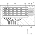
- FIG. 1 is a plan view showing a configuration of a light emitting device 10 according to the first embodiment.
- 2 is a cross-sectional view taken along line AA in FIG. 1
- FIG. 3 is a cross-sectional view taken along line CC in FIG. 1
- FIG. 4 is a cross-sectional view taken along line BB in FIG.
- FIG. 5 is a diagram for explaining the positional relationship among the first electrode 110, the extraction wiring 130, the second electrode 150, and the extraction wiring 160.
- the light-emitting device 10 is a display is illustrated.
- the light emitting device 10 includes a structure on one surface side of the substrate 100. In the example shown in this drawing, this structure extends on one surface side of the substrate 100.
- this structure is a partition wall 170, and a plurality of structures are provided on the substrate 100.
- An organic layer 140 is formed between the partition walls 170.
- the organic layer 140 is formed in a line shape.
- the partition wall 170 divides the second electrode 150 formed on the organic layer 140.
- the second electrode 150 is formed in a line shape by the partition wall 170.
- the light emitting device 10 described above may be a lighting device or a lighting device that can achieve color rendering.
- the light emitting device 10 includes a substrate 100, an organic EL element, an insulating layer 120, a partition 170, a plurality of first openings 122, a plurality of second openings 124, and a plurality of lead wires 160.
- the organic EL element is composed of a laminate in which the first electrode 110, the organic layer 140, and the second electrode 150 are stacked in this order. This organic EL element is located between the plurality of partition walls 170. That is, the organic EL element and the lead wiring 160 are located on one surface side of the substrate 100.
- the first electrode 110 is formed on the first surface side of the substrate 100 and extends in a line shape in the first direction (Y direction in FIG. 1).
- the insulating layer 120 is formed on the plurality of first electrodes 110.
- the organic layer 140 is formed on the first electrode 110.
- the second electrode 150 is formed on the organic layer 140 and extends in a second direction (X direction in FIG. 1) intersecting the first direction.
- the second electrode 150 extends in a direction (second direction to be described later) intersecting the first direction in which the plurality of first electrodes 110 extend in a plan view.
- FIGS. 1 the first electrode 110 is formed on the first surface side of the substrate 100 and extends in a line shape in the first direction (Y direction in FIG. 1).
- the insulating layer 120 is formed on the plurality of first electrodes 110.
- the organic layer 140 is formed on the first electrode 110.
- the second electrode 150 is formed on the organic layer 140 and extends in a second direction (X direction in FIG. 1) intersecting the first direction.
- the partition wall 170 is formed on a base (the insulating layer 120 in the example shown in this figure), and between the adjacent second electrodes 150 in the second direction as shown in FIG. It extends in the (X direction in FIG. 1).
- a first opening 122 is formed in the insulating layer 120 and is located at the intersection of the first electrode 110 and the second electrode 150 in plan view as shown in FIG.
- the second opening 124 is formed in the insulating layer 120 and is located at one end of each of the plurality of second electrodes 150 in plan view. Note that the insulating layer 120 having the first opening 122 and the insulating layer 120 having the second opening 124 may be formed of the same material or different materials.
- the insulating layer 120 having the second opening 124 may be formed on the outer peripheral side of the substrate 100 with respect to the insulating layer 120 having the first opening 122.
- the insulating layer 120 having the first opening 122 and the insulating layer 120 having the second opening 124 may be continuous layers or separated layers (separated).
- the organic layer 140 is sandwiched between the first electrode 110 and the second electrode 150 and has a light emitting layer 144.
- a portion of the lead-out wiring 160 on one end side is in the second opening 124 and is connected to the second electrode 150. Further, the portion of the lead-out wiring 160 on the other end side extends to the outer peripheral portion of the substrate 100 and is connected to a terminal for external connection.
- the light emitting device 10 will be described in detail.
- the substrate 100 is formed of, for example, glass or a resin material, but may be formed of other materials.
- the first electrode 110 is a transparent electrode formed of an inorganic material such as ITO (IndiumITOThin Oxide) or IZO (Indium Zinc Oxide), or a conductive polymer such as a polythiophene derivative.
- the first electrode 110 may be a metal thin film that is thin enough to transmit light. In the example shown in the figure, the first electrode 110 extends linearly in the Y direction in the figure. The end of the first electrode 110 is connected to the lead wiring 130.
- the lead-out wiring 130 is a wiring that connects the first electrode 110 and a terminal for external connection.
- the lead wire 130 is a metal wire made of a metal material or an alloy such as ITO, IZO, Al, Cr, or Ag, which is an oxidized conductive material, but is a wire formed of a conductive material other than metal. There may be.
- an extraction wiring 132 and a extraction wiring 130 formed of a material constituting the first electrode 110 that is electrically connected to the first electrode 110 are sequentially arranged. Is formed.
- the lead wires 130 and 132 are formed up to the vicinity of the first opening 122.
- the first electrode 110 is covered with an insulating film, but at least a part of the lead wiring 130 and the lead wiring 132 that are electrically connected to the first electrode 110 may be covered.
- the insulating layer 120 is a photosensitive resin such as a polyimide resin, and is formed in a desired pattern by exposure and development.
- a photosensitive resin such as a polyimide resin
- As the insulating layer 120 for example, a positive photosensitive resin is used.
- the insulating layer 120 may be a resin other than a polyimide resin, for example, an epoxy resin or an acrylic resin.
- the insulating layer 120 has the first opening 122 and the second opening 124 formed therein.
- the first opening 122 is located on the first electrode 110.
- the plurality of first openings 122 are provided at a predetermined interval.
- the plurality of first openings 122 are formed side by side in the direction in which the first electrode 110 extends, and are formed side by side in the direction in which the second electrode 150 extends. For this reason, the plurality of first openings 122 are arranged to form a matrix.
- An organic layer 140 is formed in the first opening 122.
- the organic layer 140 is formed by stacking a hole injection layer 142, a light emitting layer 144, and an electron injection layer 146. Note that part of the organic layers refers to a hole injection layer 142, a light emitting layer 144, an electron injection layer 146, a hole transport layer, or an electron transport layer described later.
- the hole injection layer 142 is in contact with the first electrode 110, and the electron injection layer 146 is in contact with the second electrode 150. In this way, the organic layer 140 is sandwiched between the first electrode 110 and the second electrode 150.
- a hole transport layer may be formed between the hole injection layer 142 and the light-emitting layer 144, and an electron transport layer may be formed between the light-emitting layer 144 and the electron injection layer 146.
- the hole injection layer 142 is formed using a coating method such as an inkjet method.
- at least one of the hole transport layer, the light-emitting layer 144, the electron transport layer, and the electron injection layer 146 may be formed by an inkjet method.
- each layer constituting the organic layer 140 is continuously formed even if it is continuously formed between the adjacent first openings 122 in the direction in which the partition 170 extends. It doesn't have to be. However, as shown in FIG. 4, the organic layer 140 is not formed around the second opening 124.
- the second openings 124 are arranged along one side of the matrix formed by the first openings 122. In other words, the second openings 124 are arranged in the direction of the plurality of first openings 122 arranged side by side along the partition wall 170. When viewed in a direction along one side (for example, the Y direction in FIG. 1), the second openings 124 are arranged at a predetermined interval in the direction along the first electrode 110. In the second opening 124, there is a lead wiring 160 or a part of the lead wiring 160.
- the lead wires 160 and 162 are formed in a region of the first surface of the substrate 100 where the first electrode 110 and the lead wires 130 and 132 are not formed.
- the present invention is not limited to this, and a part of the lead wiring 160 may be formed in a region where the lead wiring 130 is formed.
- a part of the lead wiring 132 may be formed even in a region where the lead wiring 162 is formed.
- the lead wiring 160 may be formed simultaneously with the lead wiring 130, for example, or the lead wiring 160 and the lead wiring 130 may be formed separately.
- the lead wiring 162 may be formed simultaneously with the lead wiring 132, for example, or the lead wiring 162 and the lead wiring 132 may be formed separately.
- the lead wiring 160 is formed on the lead wiring 162.
- the lead-out wiring 162 is formed of the same kind or different material as the material constituting the first electrode 110.
- ITO which is an oxidized conductive material
- ITO or an oxidized conductive material such as IZO having a composition different from that of the ITO constituting the first electrode 110 is used.
- Examples of different materials include metal materials such as Al.
- the lead-out wiring 162 is formed along the lead-out wiring 160, and the lead-out wiring 162 and the lead-out wiring 160 overlap each other. In the illustrated example, the width of the lead-out wiring 162 is larger than the width of the lead-out wiring 160, but the width is not limited to this and may be small.
- a part of the lead-out wiring 160 on one end side is covered with the insulating layer 120 and exposed through the second opening 124.
- a part of the lead wiring 160 on the other end side is led to the outside of the insulating layer 120. That is, the other end side of the lead wiring 160 is exposed to the insulating layer 120.
- the lead wiring 160 extends in a direction substantially orthogonal to the lead wiring 130.
- the second electrode 150 is connected to the lead wiring 160.
- the second electrode 150 is, for example, a metal layer formed of a metal material such as Ag or Al, or a layer formed of an oxidized conductive material such as IZO, and is formed in a direction orthogonal to the first electrode 110 in plan view. Yes.
- One second electrode 150 passes over the plurality of first openings 122.
- the second electrode 150 is connected to the lead wiring 160.
- the end of the second electrode 150 is positioned on the second opening 124, whereby the second electrode 150 and the extraction wiring 160 are connected in the second opening 124.
- a partition wall 170 is formed between the adjacent second electrodes 150.
- the partition 170 is, for example, a photosensitive resin such as a polyimide resin, and is formed in a desired pattern by being exposed and developed.
- the partition wall 170 is formed using, for example, a negative photosensitive resin.
- the partition wall 170 may be made of a resin other than a polyimide resin, for example, an inorganic material such as an epoxy resin, an acrylic resin, or silicon dioxide.
- the partition wall 170 has a trapezoidal cross-sectional shape (reverse trapezoidal shape). That is, the width of the upper surface of the partition wall 170 is larger than the width of the lower surface of the partition wall 170. For this reason, by forming the partition 170 before the second electrode 150, the plurality of second electrodes 150 can be collectively formed by using an evaporation method or a sputtering method. In the case where the plurality of second electrodes 150 are collectively formed, a conductive layer that becomes the second electrode 150 is not formed at least below the partition wall 170. For this reason, the adjacent 2nd electrode 150 can be parted by the partition 170.
- the second electrode 150 can be patterned into a free shape such as a stripe shape, a dot shape, an icon shape, or a curve. Note that a conductive layer similar to the second electrode 150 is formed on the partition wall 170.
- the partition wall 170 may have a function of preventing the coating materials constituting the organic layer 140 located under the adjacent second electrode 150 from being connected to each other. In this case, the partition wall 170 is formed before the organic layer 140.
- a conductive layer to be the first electrode 110 is formed on the substrate 100, and this conductive layer is selectively removed using etching (for example, dry etching or wet etching). Thereby, the first electrode 110 and the lead-out wiring 162 are formed on the substrate 100.
- etching for example, dry etching or wet etching
- a conductive layer to be the lead wirings 130 and 160 is formed on the substrate 100, the first electrode 110, and the lead wiring 162, and the conductive layer is etched (for example, dry etching or wet etching). Selectively remove. Thereby, the lead wires 130 and 160 are formed.
- an insulating layer is formed on the substrate 100, the first electrode 110, and the lead wires 130 and 160, and this insulating layer is selectively removed using etching (for example, dry etching or wet etching). Thereby, the insulating layer 120, the first opening 122, and the second opening 124 are formed.
- etching for example, dry etching or wet etching
- a partition wall 170 is formed on the insulating layer 120, and the partition wall 170 is selectively removed using etching (for example, dry etching or wet etching). Thereby, the partition 170 is formed.
- etching for example, dry etching or wet etching.
- the cross-sectional shape of the partition 170 can be changed to an inverted trapezoid by adjusting the conditions during exposure and development.
- the partition wall 170 is a negative resist
- the portion of the negative resist irradiated with the irradiation light from the exposure light source is cured.
- the partition 170 is formed by dissolving and removing the uncured portion of the negative resist with a developer. In these steps, by adjusting the light irradiation angle from the exposure light source, the position of the mask, the number of exposure light sources, the number of exposures, and the like, the angle of the inverted trapezoid in the cross-sectional shape of the partition wall 170 and the position of the recess 171 to be described later And the size can be adjusted.
- a light emitting device substrate as shown in FIG. 6 is formed.
- This substrate has a configuration in which the organic layer 140 and the second electrode 150 are removed from the light emitting device 10.
- the hole injection layer 142, the light emitting layer 144, and the electron injection layer 146 are formed in this order in the first opening 122.
- at least the hole injection layer 142 is formed using a coating method such as spray coating, dispenser coating, ink jetting, or printing.
- the coating material enters the first opening 122, and the coating material is dried, whereby the above-described layers are formed.
- a coating material used in the coating method a polymer material, a polymer material containing a low-molecular material, or the like is suitable.
- the coating material for example, a polyalkylthiophene derivative, a polyaniline derivative, triphenylamine, a sol-gel film of an inorganic compound, an organic compound film containing a Lewis acid, a conductive polymer, or the like can be used.
- the remaining layers (for example, the light emitting layer 144 and the electron injection layer 146) of the organic layer 140 are formed by an evaporation method. However, these layers may also be formed using any of the above-described coating methods.
- the second electrode 150 is formed on the organic layer 140 by using, for example, a vapor deposition method or a sputtering method.
- At least one of the layers other than the organic layer 140 is also formed using any of the above-described coating methods. It may be formed.
- FIG. 7 is a plan view for explaining the configuration of the partition wall 170.
- a partition 170 that is an example of a structure has a recess 171 formed in a direction that intersects the direction in which the partition 170 extends.
- the recess 171 overlaps, for example, the first opening 122 in the direction in which the partition wall 170 extends.
- the recess 171 may be further away from the second opening 124 than the first opening 122 (the recess 171 closest to the second opening 124 when a plurality of recesses 171 are formed).
- the partition 170 has a plurality of recesses 171 formed therein.
- the recess 171 is formed on at least one side surface of the partition wall 170. In the direction in which the partition wall 170 extends (X direction in the drawing), the recess 171 is provided at least at a position between the first opening 122 and the second opening 124 that are closest to the second opening 124. Yes.
- the plurality of recesses 171 may be provided at predetermined intervals. Moreover, these recessed parts 171 may be provided in one side surface of the partition 170, the other side surface, or one side surface and the other side surface. In addition to the position between the first opening 122 and the second opening 124 that are closest to the second opening 124, a plurality of recesses 171 are formed from one end of the partition wall 170 to the other end. It does not matter. Further, the recess 171 is formed from the middle of the partition wall 170 to one end or the other end other than the position between the first opening 122 and the second opening 124 that are closest to the second opening 124. It does not matter.
- the width of the recess 171 is smaller than the width of the first opening 122 in the direction in which the partition 170 extends (X direction in the figure). That is, the width of the recess 171 is smaller than the width of the organic EL element.
- the width of the recess 171 is not limited to this, and may be larger than the width of the first opening 122.
- the recess 171 is formed on the two side surfaces of the partition wall 170.
- the recess 171 formed on the first side surface which is one side surface and the recess 171 formed on the second side surface which is the other side surface are in the direction in which the partition wall 170 extends.
- the concave portion 171 (first concave portion 171) formed on the first side surface and the concave portion 171 (second concave portion 171) formed on the second side surface are at different positions. There is no overlap. Therefore, a recess 171 is formed in each of the two partition walls 170 disposed on both sides of the first opening 122 at a position overlapping the first opening 122 in the direction in which the partition wall 170 extends.
- the recesses 171 of the plurality of partition walls 170 are formed at the same position in the direction in which the partition walls 170 extend. 8 may be formed at different positions as shown in FIG. Further, in the example of FIG. 8, a plurality of recesses 171 are formed between the first opening 122 and the second opening 124 that are closest to the second opening 124. 171 may be formed.
- FIG. 9 is an enlarged view of a part of the partition wall 170 shown in FIG.
- the recess 171 is formed on the first side surface and the second side surface of the partition wall 170.
- wall 170 extends the length of the recess 171 and L 1, a first recess 171 formed in the side surface of the (first recess 171) and a recess 171 formed in the second side surface (the L 2 / L 1 ⁇ 1, where L 2 is the length of the partition wall 170 between the two recesses 171).
- the distance between the first concave portion 171 and the second concave portion 171 located next to the first concave portion 171 is equal to or larger than the width of the concave portion 171. Is preferred. In this manner, the partition wall 170 can be prevented from falling even if the recess 171 is provided.
- the cross-sectional shape of the partition 170 is an inverted trapezoid.
- the depth d of the concave portion 171 formed on the first side surface and the depth d of the concave portion 171 formed on the second side surface may be substantially equal to each other. However, the depth d may be different from each other on the first side surface or the second side surface. Further, the width of the partition wall 170 at the position of the recess 171 may be smaller than the width of the partition wall 170 in the portion where the recess 171 is not provided.
- the organic layer 140 for example, the hole injection layer 142
- the organic that protrudes from the first opening 122 that is, the region where the organic EL element is formed.
- the coating material that becomes the layer 140 may come into contact with the first side surface or the second side surface of the partition wall 170, spread in the extending direction of the partition wall 170, and reach the second opening 124.
- the partition 170 includes at least a first opening 122 located closest to the second opening 124 in the direction in which the partition 170 extends (X direction in the drawing) and the second opening 124.
- a recess 171 is provided at a position therebetween. Therefore, even if the coating material that becomes the organic layer 140 from the first opening 122 contacts the first side surface or the second side surface of the partition wall 170 and wets and spreads in the extending direction of the partition wall 170, the coating material is It enters the recess 171. For this reason, it can suppress that the coating material used as the organic layer 140 reaches
- the end portion of the coating material constituting the organic layer 140 is located closer to the first opening 122 than the second opening 124.
- the concave portions 171 are formed on both of the two side surfaces of the partition wall 170, it is possible to further prevent the coating material from reaching the second opening 124.
- the width of the recess 171 is smaller than the width of the first opening 122 in the direction in which the partition wall 170 extends. At least one recess 171 is disposed adjacent to the first opening 122. For this reason, even if the coating material that becomes the organic layer 140 overflows from the first opening 122, the overflowing coating material can be prevented from reaching the adjacent first opening 122. As a result, it is possible to further suppress the end portion of the organic layer 140 from reaching the second opening 124.
- the cross-sectional shape of the partition wall 170 at the position of the recess 171 is an inverted trapezoid. Therefore, the coating material that becomes the organic layer 140 that has entered the recess 171 is likely to accumulate between the side surface of the partition wall 170 and the surface of the insulating layer 120. Accordingly, it is possible to further suppress the organic layer 140 from reaching the second opening 124.
- FIG. 10 is a cross-sectional view illustrating a configuration of the partition wall 170 included in the light emitting device 10 according to the second embodiment.
- FIG. 11 is a diagram showing the DD cross section of FIG. 10 together with the insulating layer 120, the first opening 122, and the second opening 124.
- FIG. 12 is a view showing the EE cross section of FIG. 10 together with the insulating layer 120, the first opening 122, and the second opening 124.
- the light emitting device 10 according to the present embodiment has the same configuration as that of the light emitting device 10 according to the first embodiment except for the configuration of the partition wall 170.
- the partition wall 170 has a concave portion in the lower portion (that is, the substrate 100 side).
- a through hole 172 is shown as a recess. That is, a through hole 172 is formed at the boundary between the partition wall 170 and the insulating layer 120.
- the through-hole 172 penetrates the partition wall 170 in a direction intersecting with the direction in which the partition wall 170 extends.
- the through-hole 172 that is a recess is formed from the first side surface to the second side surface of the partition wall 170.
- the through hole 172 penetrates the partition wall 170 in a direction substantially perpendicular to the partition wall 170 (Y direction in the figure).
- the through hole 172 is adjacent to the first opening 122.
- the through hole 172 is provided at a position overlapping the first opening 122 in the extending direction of the partition wall 170.
- no other structure such as wiring is formed inside the through-hole 172, but the present invention is not limited to this, and the coating material constituting the organic layer 140 is present in the through-hole 172. It doesn't matter.
- the through hole 172 may not be adjacent to the first opening 122.
- the through hole 172 may be provided at a position between the adjacent first openings 122 in the extending direction of the partition wall 170.
- a shape (concave portion) that is recessed inward from the side surface of the partition wall 170 may be provided.
- the width of a portion of the partition wall 170 located between adjacent through holes 172 is L 3 and the width of the through hole 172 is L 4 , it is preferable that L 4 / L 3 ⁇ 1. That is, in the extending direction of the partition wall 170, the distance between the through hole 172 and the through hole 172 located adjacent to the through hole 172 is equal to the width of the through hole 172 in the extending direction of the partition wall 170. Smaller is preferred.
- L 4 / L 3 ⁇ 1 the width of the through hole 172 can be made larger than the width of the first opening 122, and the thickness of the organic layer 140 can be made uniform.
- the through-hole 172 in the partition wall 170 it is possible to suppress variation in the thickness of the organic layer 140 in each first opening 122. Moreover, even if the through-hole 172 is provided, the partition wall 170 can be prevented from falling.
- the height of the through hole 172 is, for example, half or less of the height of the partition wall 170.
- the height of the through hole 172 is not limited to this.
- L 3 is formed larger than the interval G between the two adjacent first openings 122 in the direction in which the partition wall 170 extends.
- L 3 is not limited to this, but may be smaller than the distance G.
- the through hole 172 is formed, for example, by relatively reducing the width of the portion of the partition wall 170 where the through hole 172 is to be formed.
- a method of narrowing a part of the partition 170 for example, there is a method of changing an opening pattern of a mask.
- the through hole 172 may be formed using other methods.
- adjusting the exposure time and light intensity of the exposure light source can be mentioned. Specifically, the exposure is performed in two portions on the negative resist portion where the through hole 172 is not formed and the negative resist portion where the through hole 172 is formed.
- the exposure time is set to be short or the light intensity is set to be low for the negative resist portion where the through-hole 172 is formed.
- the exposure time is increased or the light intensity is increased as compared with the negative resist portion where the through hole 172 is formed.
- the manufacturing method of the light emitting device 10 according to the present embodiment is the same as the method shown in the first embodiment except for this point.
- the through-hole 172 is formed in the partition wall 170.
- the thickness of the organic layer 140 in the first opening 122 can be made uniform.
- variation in the thickness of the organic layer 140 in the plurality of first openings 122 can be suppressed.
- the organic layer 140 becomes thicker near the partition wall 170, and the film thickness uniformity of the organic layer 140 in the first opening 122 serving as the organic EL element is increased. Decreases.
- a quality defect such as a difference in the emission color on the central side and the emission color on the outer peripheral side occurs in the organic EL element. In this embodiment, such a phenomenon can be suppressed.
- the coating material for forming any layer of the organic layer 140 protrudes from the first opening 122 and reaches the side surface of the partition wall 170
- the coating material is applied to the side surface of the partition wall 170. Crawling up at least the lower end. For this reason, the angle of the side surface of the partition wall 170 approaches a forward taper.
- the adjacent second electrode 150 may not be divided by the partition 170.
- the partition 170 is provided with the through hole 172, at least a part of the coating material that becomes the organic layer 140 protruding from the first opening 122 enters the through hole 172, and as a result. 32 and FIG.
- the angle of the side surface of the partition wall 170 does not approach a forward taper. Moreover, it can suppress that the organic layer 140 becomes thick too much.
- 32 corresponds to the cross-sectional view of FIG. 10, and
- FIG. 33 corresponds to the FF cross section of FIG.
- the organic layer 140 flows out to the adjacent region through the through hole 172. For this reason, it can suppress that a part of organic layer 140 crawls up the side surface of the partition 170, and the uniformity of the thickness of the organic layer 140 falls.
- at least one layer of the two organic layers 140 adjacent to each other via the partition wall 170 may be connected to each other via the through hole 172.
- the first electrode 110 may be formed on the insulating layer 120 using a coating method after the insulating layer 120 and the partition 170 are formed.
- the coating material to be the first electrode 110 wets and spreads on the surface of the insulating layer 120 constituting the first opening 122 through the through hole 172.
- the first electrode 110 can be formed to have a uniform thickness in the first opening 122, and light emission unevenness can be suppressed. Further, variation in the thickness of the first electrode 110 in the plurality of first openings 122 can be suppressed.
- FIG. 13 is a plan view illustrating a configuration of a main part of the light emitting device 10 according to the third embodiment, and corresponds to FIG. 11 in the second embodiment.
- the light emitting device 10 according to the present embodiment has the same configuration as that of the light emitting device 10 according to the second embodiment, except that a recess 171 is provided instead of the through hole 172.
- the recess 171 according to the present embodiment is not provided in the entire partition 170 when viewed in the height direction, and is provided at least in the lower part, except for the recess 171 according to the first embodiment. It is the same composition as.
- the recess 171 is formed on either of the two side surfaces of the partition wall 170 as in the first embodiment.
- the positions of the recess 171 formed on the first side surface and the recess 171 formed on the second side surface are at least substantially the same in the direction in which the partition wall 170 extends.
- these recesses 171 may be staggered.
- the distance L 5 between two recesses 171 adjacent in the direction wall 170 extends, are formed small with respect to the spacing G of the two first openings 122 adjacent. Thereby, the thickness of the organic layer 140 in the first opening 122 can be made uniform. Further, variation in the thickness of the first electrode 110 in the plurality of first openings 122 can be suppressed.
- the side surface of the partition wall 170 is not crawled. For this reason, it can suppress that the angle of the side surface of the partition 170 approaches a forward taper, and the 2nd electrode 150 can be parted by the partition 170.
- FIG. 14 is a cross-sectional view illustrating a configuration of the insulating layer 120 and the partition 170 included in the light emitting device 10 according to the fourth embodiment.
- FIG. 15 is a plan view showing the partition wall 170 and the surrounding structure.
- the light emitting device 10 according to the present embodiment is the same as the third embodiment except that the partition wall 170 has neither the through-hole 172 nor the recess 171, but a recess 126 is formed at least on the insulating layer 120.
- the configuration is the same as that of the light emitting device 10 according to the embodiment.
- a plurality of the recesses 126 are formed for one partition 170.
- the arrangement and width of the recesses 126 in the direction in which the partition 170 extends are the same as the arrangement of the recesses 171 in the third embodiment.
- the recess 126 when viewed in the width direction of the partition wall 170, is formed so as to include a region overlapping the lower end of the side surface of the partition wall 170 in plan view. That is, in a plan view, each of the plurality of recesses 126 is partially located outside the partition wall 170 and partially overlaps the partition wall 170.
- the recess 126 does not penetrate the insulating layer 120 in the thickness direction. However, as shown in FIG. 16, the recess 126 may penetrate the insulating layer 120 in the thickness direction.
- the recess 126 is formed, for example, in the same process as the first opening 122 and the second opening 124.
- the recess 126 may be formed by devising the exposure condition of the insulating layer 120. For example, the irradiation angle of the exposure light, the position of the opening of the exposure mask, the number of exposure light sources, the number of exposures can be adjusted, and the position, number, shape of the recess, and depth can be adjusted.
- the recess 126 may be formed by etching the insulating layer 120 as described above.
- the present embodiment it is possible to suppress variation in the thickness of the organic layer 140 in each first opening 122, and it is possible to suppress the occurrence of light emission unevenness. Moreover, when the insides of the plurality of first openings 122 are compared, variation in the thickness of the organic layer 140 can be suppressed. Moreover, when the 1st electrode 110 is formed with a coating material, it can suppress that the thickness of the 1st electrode 110 varies. Further, as shown in the cross-sectional view of FIG. 34, at least a part of the coating material of the organic layer 140 that protrudes from the first opening 122 enters the recess 126 and is then dammed by the lower surface of the partition wall 170. It becomes difficult to scoop up the side. For this reason, it can suppress that the angle of the side surface of the partition 170 approaches a trapezoid shape (forward taper) from an inverted trapezoid shape similarly to 3rd Embodiment.
- a trapezoid shape forward taper
- FIG. 17 is a cross-sectional view illustrating the configuration of the insulating layer 120 and the partition 170 included in the light emitting device 10 according to the fifth embodiment.
- the light emitting device 10 according to the present embodiment has the same configuration as that of the light emitting device 10 according to the fourth embodiment, except that the recess 126 passes through a portion overlapping the partition wall 170 in plan view.
- the recess 126 may be formed as a recess having the same thickness as the insulating layer 120 in the depth direction.
- the present embodiment similarly to the fourth embodiment, it is possible to suppress the variation in the thickness of the organic layer 140 in each first opening 122, and it is possible to suppress the occurrence of light emission unevenness. Moreover, when the insides of the plurality of first openings 122 are compared, variation in the thickness of the organic layer 140 can be suppressed. Moreover, when the 1st electrode 110 is formed with a coating material, it can suppress that the thickness of the 1st electrode 110 varies. Moreover, it can suppress that the angle of the side surface of the partition 170 approaches trapezoid shape (forward taper) from an inverted trapezoid shape. Moreover, since the recessed part 126 has penetrated the partition 170 in the width direction, the capacity
- FIG. 19 is a cross-sectional view illustrating configurations of the substrate 100, the insulating layer 120, and the partition wall 170 included in the light emitting device 10 according to the sixth embodiment.
- the light emitting device 10 according to the present embodiment has the same configuration as the light emitting device 10 according to the fifth embodiment except for the following points.
- a recess 102 is formed in a region of the first surface of the substrate 100 that overlaps the recess 126. For this reason, when forming the insulating layer 120, the recess 126 can be formed along the recess 102. Therefore, according to the present embodiment as well as the fifth embodiment, it is possible to suppress the variation in the thickness of the organic layer 140 in each first opening 122 and to prevent the occurrence of uneven light emission. Moreover, when the insides of the plurality of first openings 122 are compared, variation in the thickness of the organic layer 140 can be suppressed. Moreover, when the 1st electrode 110 is formed with a coating material, it can suppress that the thickness of the 1st electrode 110 varies. Further, it is possible to sufficiently suppress the coating material of the organic layer 140 from climbing up the side wall of the partition wall 170.
- FIG. 20 is a plan view showing the configuration of the light emitting device 10 according to the seventh embodiment. This figure shows a case corresponding to the DD cross section in FIG. 10 and the through hole 172 between the first opening 122 and the second opening 124 closest to the lead-out wiring 160.
- the light emitting device 10 according to the present embodiment includes at least a through hole between the second opening 124 and the first opening 122 located closest to the first opening 122 side, for example, the second opening 124 from the lead-out wiring 160.
- the configuration is the same as that of the light-emitting device 10 according to the second embodiment except that 172 is included.
- the through hole 172 is positioned between the organic EL element closest to one end portion of the extraction wiring 160 and one end portion of the extraction wiring 160 or the second opening 124. is doing.
- the configuration of the through hole 172 is the same as the configuration of the through hole 172 according to the second embodiment except for the arrangement position.
- the through hole 172 is provided at a position different from the position of the first opening 122 and the position of the second opening 124 in the direction in which the partition wall 170 extends.
- the present invention is not limited to this, and at least a part of the through hole 172 may be at least one of the position of the first opening 122 and the position of the second opening 124.
- the partition wall 170 may have at least one through-hole 172 at a position different from the position of the first opening 122 in the extending direction of the partition wall 170 as in the second embodiment.
- the through hole 172 may be formed at a position between the adjacent first openings 122 in the extending direction of the partition wall 170.
- the coating material forming the organic layer 140 that protrudes from the first opening 122 spreads wet along the side wall of the partition wall 170 toward the second opening 124, the coating material is passed through the through-hole 172. Can be poured into.
- the flow of the coating material of the organic layer 140 can be blocked by a portion of the inner wall of the through hole 172 located near the second opening 124. Therefore, this coating material can be prevented from reaching the second opening 124.
- the coating material reaches the second opening 124 as described above even if the concave portion 171 having the same configuration as that of the third embodiment is provided instead of the through-hole 172. This can be suppressed.
- the coating material as described above can be used as the second coating material. Reaching the opening 124 can be suppressed.
- FIG. 23 is a plan view showing the partition wall 170 and its surrounding structure in the light emitting device 10 according to the eighth embodiment.
- the light emitting device 10 according to the present embodiment has the same configuration as the light emitting device 10 according to the first embodiment, except for the structure of the partition wall 170.
- the cross-sectional shape of the partition 170 that is, the size of the partition 170 is larger than the first opening 122 located closest to the second opening 124 in the direction in which the partition 170 extends. Or different in shape.
- a wall surface 175 is provided at the boundary.
- the partition wall 170 has a first partition wall portion 174 located on the first opening 122 side and a second partition wall portion 176 located on the second opening 124 side with the wall surface 175 as a boundary. Yes.
- the width of the lower surface of the first partition wall portion 174 is smaller than the width of the lower surface of the second partition wall portion 176.
- the width of the lower surface of the first partition wall 174 in contact with the insulating layer 120 is smaller than the width of the lower surface of the second partition wall 176 in contact with the insulating layer 120.
- the width of the first partition in the extending direction of the partition 170 is at least longer than the first opening 122.
- variety of an upper surface is larger than the width
- the cross-sectional shape is an inverted trapezoid. For this reason, when forming the 2nd electrode 150 grade
- the cross-sectional shape of the first partition wall 174 is different from the cross-sectional shape of the second partition wall 176.
- the width of a part of the second partition wall part 176 connected to the insulating layer 120 in the direction intersecting the extending direction of the partition wall 170 is the same as the width of a part of the first partition wall part 174 connected to the insulating layer 120.
- it is formed large.
- the adhesive strength of the partition 170 with respect to the insulating layer 120 improves, and it can suppress that the partition 170 falls down.
- the coating material of the organic layer 140 protruding from the first opening 122 can be prevented from touching the side wall of the first partition wall portion 174.
- the first partition wall portion 174 is narrower than the second partition wall portion 176 in the width of the portion in contact with the insulating layer 120. For this reason, it can suppress that the coating material of the organic layer 140 which protruded from the 1st opening 122 touches the side surface of the 1st partition part 174.
- FIG. When the coating material of the organic layer 140 comes into contact with the partition 170, the organic layer 140 becomes thicker near the partition 170. In the present embodiment, such a phenomenon can be suppressed, and the uniformity of the thickness of the organic layer 140 in the portion that becomes the organic EL element can be improved.
- the width of the lower end portion of the first partition wall portion 174 that is, the width of the portion connected to the insulating layer 120 is narrower than the width of the lower end portion of the second partition wall portion 176. That is, the portion where the first partition wall 174 is in contact with the insulating layer 120 is relatively small. Therefore, even if at least a part of the organic layer 140 touches the side wall of the first partition wall portion 174, as shown in the cross-sectional view of FIG.
- the second electrode 150 can be divided. Moreover, it can suppress that the coating material of the organic layer 140 is pulled by the side surface of the 1st partition part 174. FIG. Therefore, the uniformity of the film thickness of the organic layer 140 can be improved.
- the coating material of the organic layer 140 protruding from the first opening 122 can be prevented from touching the side surface of the first partition wall 174, the coating material of the organic layer 140 enters the second opening 124 along the side wall of the partition wall 170. It is also possible to suppress spreading wet.
- the coating material of the organic layer 140 can be blocked by the wall surface 175. Therefore, the coating material for the organic layer 140 can be prevented from reaching the second opening 124.
- the width of the lower surface of the first partition wall portion 174 is narrower than the width of the lower surface of the second partition wall portion 176, the side surface of the first partition wall portion 174 and the connection portion of the wall surface 175 form a corner. is doing. In this case, the coating material of the organic layer 140 can be easily damped at the corners.
- the width of the portion where the first partition 174 and the insulating layer 120 are in contact with each other may be substantially zero.
- the lower end of the first partition wall 174 may be separated from the base (in the example shown in this figure, the insulating layer 120.
- the extending direction of the partition 170 in FIG. As shown in the cross-sectional view (that is, the GG cross-sectional view in FIG. 37), the second partition 176 is provided at both ends of the first partition 174.
- the lower end of the first partition 174 is It will be located above the lower end of the two partition walls 176.
- the first partition walls 174 are supported by the second partition walls 176 at both ends.
- the cross section of the first partition wall 174 may have a curved shape in which the side corresponding to the side surface is recessed inward. Also in this case, as shown in the cross-sectional view of FIG. 36, even if at least a part of the organic layer 140 touches the side wall of the first partition wall 174, the cross-sectional shape of the first partition wall 174 is inverted trapezoidal.
- the second electrode 150 can be divided.
- the first partition 174 and the second partition 176 are connected. However, the first partition 174 and the second partition 176 may be separated. In this case, a space is provided between the first partition wall portion 174 and the second partition wall portion 176. Further, the first partition 174 and the second partition 176 may be formed of the same material and in the same process, but the first partition 174 and the second partition 176 may be formed of separate processes. . In this case, the first partition 174 and the second partition 176 may be formed of different materials.
- FIG. 26 is a plan view showing the partition wall 170 and the surrounding structure in the light emitting device 10 according to the ninth embodiment. This figure corresponds to the DD section of FIG.
- the light emitting device 10 according to the present embodiment has the same configuration as that of the light emitting device 10 according to the eighth embodiment, except that the partition wall 170 has a through hole 172.
- the position of the through hole 172 is at the position of the first opening 122 in the direction in which the partition wall 170 extends, and the width of the through hole 172 in the extending direction of the partition wall 170 is smaller than the width of the first opening 122.
- the through hole 172 is formed below the first partition wall 174, that is, at the boundary between the insulating layer 120 and the first partition wall 174.
- the uniformity of the thickness of the organic layer 140 in the portion to be the organic EL element can be improved.
- the cross-sectional shape of the first partition wall 174 can be maintained in an inverted trapezoidal shape, and the second electrode 150 can be divided. Further, it is possible to prevent the coating material of the organic layer 140 from spreading along the side wall of the partition wall 170 toward the second opening 124. In addition, the coating material of the organic layer 140 can be blocked by the wall surface 175. Further, since the through hole 172 is provided, the uniformity of the thickness of the organic layer 140 in the portion to be the organic EL element can be improved as in the second embodiment.
- the length of the portion of the first partition 174 that is separated from the insulating layer 120 is smaller than the portion of the second partition 176 that is in contact with the insulating layer 120.
- the partition wall 170 does not fall down.
- the partition wall 170 for example, both the first partition wall portion 174 and the second partition wall portion 176 may have a shape in which a plurality of partition wall portions 178 are stacked in a plurality of stages.
- the plurality of partition walls 178 have an inverted trapezoidal cross section.
- the through-hole 172 may be partially formed in the lower part of the at least one partition part 178 located in the second stage or more by the same method as the partition 170 in the second embodiment. In this case, the through hole 172 can be separated from the upper surface of the insulating layer 120.
- the cross-sectional shape of the first partition wall portion 174 is a shape in which the partition wall portions 178 shown in FIG. 27 are stacked
- the cross-sectional shape of the second partition wall portion 176 is the partition wall 170 as shown in FIG. You can also. Further, the matters described in the above-described embodiment can be combined with this embodiment.
- FIG. 28 is a plan view showing the configuration of the light emitting device 10 according to the example. 29 is a sectional view taken along line AA in FIG. 28, FIG. 30 is a sectional view taken along line CC in FIG. 28, and FIG. 31 is a sectional view taken along line BB in FIG.
- the light emitting device 10 according to this example has the same configuration as that of the light emitting device 10 according to any one of Embodiments 1 to 9, except that the insulating layer 120 is not provided.
- the partition 170 is formed on the substrate 100 and the first electrode 110. That is, in this embodiment, the base of the partition wall 170 is the substrate 100.
- the organic layer 140 is formed in a stripe shape in a region located between the partition walls 170 on the substrate 100 and the first electrode 110. Further, the width of the organic layer 140 is wider than the width of the second electrode 150 in order to prevent the first electrode 110 and the second electrode 150 from being short-circuited. Note that the organic layer 140 may be formed only in a region on the first electrode 110 where the first opening 122 was present. Although the organic layer 140 is formed in a stripe shape, the organic layer 140 may be formed in a dot shape.
- the coating material to be the organic layer 140 can be further prevented from reaching the second opening.
- the cross-sectional shape of the partition wall 170 can be maintained in a reverse taper.
Abstract
Selon l'invention, des secondes électrodes (150) sont formées sur une couche d'isolation (120). Ces secondes électrodes (150) croisent une pluralité de premières électrodes (110) en vue en plan, mais leurs extrémités ne se superposent à aucune des premières électrodes (110). Une paroi de cloisonnement (170) se prolonge entre les secondes électrodes (150) adjacentes. Des premières ouvertures (122) sont formées sur la couche d'isolation (120), et se superposent aux points d'intersection entre les premières électrodes (110) et les secondes électrodes (150). Des secondes ouvertures (124) sont formées sur la couche d'isolation (120), et sont positionnées sur chacune des extrémités de la pluralité de secondes électrodes (150) en vue en plan. Une pluralité de parties en retrait (171) est formée sur la paroi de cloisonnement (170). Au moins une partie de ces parties en retrait (171) se superpose à la première ouverture (122) positionnée le plus près des secondes ouvertures (124).
Priority Applications (2)
| Application Number | Priority Date | Filing Date | Title |
|---|---|---|---|
| PCT/JP2013/051790 WO2014115333A1 (fr) | 2013-01-28 | 2013-01-28 | Dispositif luminescent |
| JP2014558411A JPWO2014115333A1 (ja) | 2013-01-28 | 2013-01-28 | 発光装置 |
Applications Claiming Priority (1)
| Application Number | Priority Date | Filing Date | Title |
|---|---|---|---|
| PCT/JP2013/051790 WO2014115333A1 (fr) | 2013-01-28 | 2013-01-28 | Dispositif luminescent |
Publications (1)
| Publication Number | Publication Date |
|---|---|
| WO2014115333A1 true WO2014115333A1 (fr) | 2014-07-31 |
Family
ID=51227146
Family Applications (1)
| Application Number | Title | Priority Date | Filing Date |
|---|---|---|---|
| PCT/JP2013/051790 WO2014115333A1 (fr) | 2013-01-28 | 2013-01-28 | Dispositif luminescent |
Country Status (2)
| Country | Link |
|---|---|
| JP (1) | JPWO2014115333A1 (fr) |
| WO (1) | WO2014115333A1 (fr) |
Cited By (3)
| Publication number | Priority date | Publication date | Assignee | Title |
|---|---|---|---|---|
| WO2015182096A1 (fr) * | 2014-05-27 | 2015-12-03 | 株式会社Joled | Panneau d'affichage |
| JP2016157645A (ja) * | 2015-02-25 | 2016-09-01 | パイオニア株式会社 | 発光装置 |
| TWI776244B (zh) * | 2020-09-28 | 2022-09-01 | 曜凌光電股份有限公司 | 發光二極體結構 |
Citations (6)
| Publication number | Priority date | Publication date | Assignee | Title |
|---|---|---|---|---|
| JP2000294379A (ja) * | 1999-04-07 | 2000-10-20 | Casio Comput Co Ltd | 有機el発光装置 |
| JP2004514256A (ja) * | 2000-11-17 | 2004-05-13 | コーニンクレッカ フィリップス エレクトロニクス エヌ ヴィ | 有機エレクトロルミネセンス・デバイスおよびその製造方法 |
| JP2004288403A (ja) * | 2003-03-19 | 2004-10-14 | Optrex Corp | 有機elディスプレイの製造方法および有機elディスプレイ |
| WO2010070800A1 (fr) * | 2008-12-18 | 2010-06-24 | パナソニック株式会社 | Dispositif électroluminescent el organique |
| JP2011090909A (ja) * | 2009-10-22 | 2011-05-06 | Sumitomo Chemical Co Ltd | 有機el装置用基板およびそれを用いた有機el装置の製造方法 |
| WO2011093115A1 (fr) * | 2010-01-29 | 2011-08-04 | 住友化学株式会社 | Dispositif émetteur de lumière |
-
2013
- 2013-01-28 JP JP2014558411A patent/JPWO2014115333A1/ja active Pending
- 2013-01-28 WO PCT/JP2013/051790 patent/WO2014115333A1/fr active Application Filing
Patent Citations (6)
| Publication number | Priority date | Publication date | Assignee | Title |
|---|---|---|---|---|
| JP2000294379A (ja) * | 1999-04-07 | 2000-10-20 | Casio Comput Co Ltd | 有機el発光装置 |
| JP2004514256A (ja) * | 2000-11-17 | 2004-05-13 | コーニンクレッカ フィリップス エレクトロニクス エヌ ヴィ | 有機エレクトロルミネセンス・デバイスおよびその製造方法 |
| JP2004288403A (ja) * | 2003-03-19 | 2004-10-14 | Optrex Corp | 有機elディスプレイの製造方法および有機elディスプレイ |
| WO2010070800A1 (fr) * | 2008-12-18 | 2010-06-24 | パナソニック株式会社 | Dispositif électroluminescent el organique |
| JP2011090909A (ja) * | 2009-10-22 | 2011-05-06 | Sumitomo Chemical Co Ltd | 有機el装置用基板およびそれを用いた有機el装置の製造方法 |
| WO2011093115A1 (fr) * | 2010-01-29 | 2011-08-04 | 住友化学株式会社 | Dispositif émetteur de lumière |
Cited By (4)
| Publication number | Priority date | Publication date | Assignee | Title |
|---|---|---|---|---|
| WO2015182096A1 (fr) * | 2014-05-27 | 2015-12-03 | 株式会社Joled | Panneau d'affichage |
| US9812516B2 (en) | 2014-05-27 | 2017-11-07 | Joled Inc. | Display panel |
| JP2016157645A (ja) * | 2015-02-25 | 2016-09-01 | パイオニア株式会社 | 発光装置 |
| TWI776244B (zh) * | 2020-09-28 | 2022-09-01 | 曜凌光電股份有限公司 | 發光二極體結構 |
Also Published As
| Publication number | Publication date |
|---|---|
| JPWO2014115333A1 (ja) | 2017-01-26 |
Similar Documents
| Publication | Publication Date | Title |
|---|---|---|
| JP6552790B2 (ja) | チャネルを持つ画素定義膜を備えた有機発光表示装置 | |
| JP2020531882A (ja) | Oled表示マザーボード及びその製造方法、oled表示パネルの製造方法及びそのoled表示装置 | |
| WO2015072063A1 (fr) | Panneau d'affichage électroluminescent organique, son procédé de fabrication et dispositif d'affichage électroluminescent organique | |
| WO2014115333A1 (fr) | Dispositif luminescent | |
| WO2014115335A1 (fr) | Dispositif électroluminescent | |
| JP6207928B2 (ja) | 発光装置の製造方法 | |
| KR100768692B1 (ko) | 유기 발광 소자 및 그의 제조 방법 | |
| WO2014115337A1 (fr) | Dispositif luminescent | |
| WO2014115334A1 (fr) | Dispositif luminescent | |
| JP6297604B2 (ja) | 発光装置 | |
| JP2016119201A (ja) | 発光装置 | |
| WO2014162453A1 (fr) | Structure de liaison, et dispositif luminescent | |
| JP6441595B2 (ja) | 発光装置 | |
| JP6164982B2 (ja) | 発光装置 | |
| JP6266599B2 (ja) | 光学装置 | |
| JP6341692B2 (ja) | 発光装置 | |
| JP4305825B2 (ja) | 有機elディスプレイパネル、及びその製造方法 | |
| WO2014162448A1 (fr) | Dispositif électroluminescent | |
| JP6233093B2 (ja) | 有機el装置 | |
| JP6371532B2 (ja) | 発光装置 | |
| JP2014203525A (ja) | 接合構造および発光装置 | |
| JP2016072283A (ja) | 発光装置 | |
| WO2017122360A1 (fr) | Dispositif électroluminescent | |
| WO2014162450A1 (fr) | Dispositif électroluminescent | |
| JP2019133959A (ja) | 発光装置 |
Legal Events
| Date | Code | Title | Description |
|---|---|---|---|
| 121 | Ep: the epo has been informed by wipo that ep was designated in this application |
Ref document number: 13872617 Country of ref document: EP Kind code of ref document: A1 |
|
| ENP | Entry into the national phase |
Ref document number: 2014558411 Country of ref document: JP Kind code of ref document: A |
|
| NENP | Non-entry into the national phase |
Ref country code: DE |
|
| 122 | Ep: pct application non-entry in european phase |
Ref document number: 13872617 Country of ref document: EP Kind code of ref document: A1 |