WO2014109290A1 - 室温推定装置、プログラム - Google Patents
室温推定装置、プログラム Download PDFInfo
- Publication number
- WO2014109290A1 WO2014109290A1 PCT/JP2014/000056 JP2014000056W WO2014109290A1 WO 2014109290 A1 WO2014109290 A1 WO 2014109290A1 JP 2014000056 W JP2014000056 W JP 2014000056W WO 2014109290 A1 WO2014109290 A1 WO 2014109290A1
- Authority
- WO
- WIPO (PCT)
- Prior art keywords
- room temperature
- outside air
- prediction
- time
- data
- Prior art date
Links
Images


Classifications
-
- F—MECHANICAL ENGINEERING; LIGHTING; HEATING; WEAPONS; BLASTING
- F24—HEATING; RANGES; VENTILATING
- F24F—AIR-CONDITIONING; AIR-HUMIDIFICATION; VENTILATION; USE OF AIR CURRENTS FOR SCREENING
- F24F11/00—Control or safety arrangements
- F24F11/30—Control or safety arrangements for purposes related to the operation of the system, e.g. for safety or monitoring
-
- F—MECHANICAL ENGINEERING; LIGHTING; HEATING; WEAPONS; BLASTING
- F24—HEATING; RANGES; VENTILATING
- F24F—AIR-CONDITIONING; AIR-HUMIDIFICATION; VENTILATION; USE OF AIR CURRENTS FOR SCREENING
- F24F11/00—Control or safety arrangements
- F24F11/62—Control or safety arrangements characterised by the type of control or by internal processing, e.g. using fuzzy logic, adaptive control or estimation of values
-
- F—MECHANICAL ENGINEERING; LIGHTING; HEATING; WEAPONS; BLASTING
- F24—HEATING; RANGES; VENTILATING
- F24F—AIR-CONDITIONING; AIR-HUMIDIFICATION; VENTILATION; USE OF AIR CURRENTS FOR SCREENING
- F24F11/00—Control or safety arrangements
- F24F11/89—Arrangement or mounting of control or safety devices
-
- F—MECHANICAL ENGINEERING; LIGHTING; HEATING; WEAPONS; BLASTING
- F24—HEATING; RANGES; VENTILATING
- F24F—AIR-CONDITIONING; AIR-HUMIDIFICATION; VENTILATION; USE OF AIR CURRENTS FOR SCREENING
- F24F11/00—Control or safety arrangements
- F24F11/62—Control or safety arrangements characterised by the type of control or by internal processing, e.g. using fuzzy logic, adaptive control or estimation of values
- F24F11/63—Electronic processing
- F24F11/64—Electronic processing using pre-stored data
-
- F—MECHANICAL ENGINEERING; LIGHTING; HEATING; WEAPONS; BLASTING
- F24—HEATING; RANGES; VENTILATING
- F24F—AIR-CONDITIONING; AIR-HUMIDIFICATION; VENTILATION; USE OF AIR CURRENTS FOR SCREENING
- F24F2110/00—Control inputs relating to air properties
- F24F2110/10—Temperature
-
- F—MECHANICAL ENGINEERING; LIGHTING; HEATING; WEAPONS; BLASTING
- F24—HEATING; RANGES; VENTILATING
- F24F—AIR-CONDITIONING; AIR-HUMIDIFICATION; VENTILATION; USE OF AIR CURRENTS FOR SCREENING
- F24F2110/00—Control inputs relating to air properties
- F24F2110/10—Temperature
- F24F2110/12—Temperature of the outside air
Definitions
- the present invention relates to a room temperature estimation device that predicts a room temperature on a target date and time, and a program that causes a computer to function as the room temperature estimation device.
- Document 1 describes a technique for predicting a change in room temperature based on the history of the measured room temperature, where the information of the environment to be measured is room temperature. Furthermore, in Document 1, the operation start time and the heating start time of the heating device are determined from the predicted change in room temperature and outside temperature, the heat amount required for heating the room (heating load heat amount) and the heating capacity of the heating device. ing. That is, in the document 1, a predicted value of the room temperature and the outside air temperature is determined, and a heating load heat amount for setting the room temperature to a desired set temperature is determined based on the predicted value.
- the arrangement described in reference 1 predicts room temperature to determine the heating load heat.
- prediction of room temperature is based on history, and a technique for predicting room temperature using other factors that determine room temperature is not described.
- Document 2 describes a technology for predicting the temperature in a vehicle compartment by using the amount of solar radiation predicted together with the measured room temperature and the outside air temperature, where the information of the environment to be measured is room temperature and the outside air temperature. It is done.
- the configuration described in Document 2 is a technology for predicting the temperature in the passenger compartment, and since the temperature in the passenger compartment follows a change in the outside air temperature in a short time, the temperature inside the passenger compartment is predicted from the outside air temperature and the amount of solar radiation. It is relatively easy to do. However, the temperature of the room of the building does not change immediately even if the outside air temperature changes, and depends on the thermal characteristics such as the thermal insulation performance of the room. It is difficult to predict room temperature from ambient temperature.
- a computer simulation technology is known to obtain the room temperature of a building from various factors such as the outside air temperature, the heat insulation performance of the building, solar radiation, ventilation, rainfall, the presence or absence of people, and the like.
- a large amount of information is required, and information that may require another measurement to obtain an accurate value may be included. Can not be used conveniently.
- An object of the present invention is to provide a room temperature estimation device for estimating the room temperature of a room in a building without performing complicated computer simulation based on information of the measured environment, and further, a computer is used as the room temperature estimation device. It aims to provide a program that makes it work.
- the room temperature estimation apparatus includes a room temperature acquisition unit that acquires room temperature data from a room temperature measurement unit, an outside air temperature acquisition unit that acquires data of an outside air temperature from an outside air temperature measurement unit, and the room temperature acquired by the room temperature acquisition unit.
- a storage unit for storing data of the data and data of the outside air temperature acquired by the outside air temperature acquisition unit in association with the date and time when each was measured, and specifying each of a plurality of days in a predetermined extraction period stored in the storage unit
- a prediction equation generation unit that generates a prediction equation that represents the relationship between the room temperature and the outside air temperature with respect to the specific time using the data of the room temperature and the outside air temperature at time, and a predicted transition acquisition unit that acquires the predicted change for the outside air temperature
- the room temperature at the time of interest is obtained by applying the outside air temperature of the time of interest corresponding to the specific time to the prediction equation using the transition of the outside air temperature acquired by the predicted transition acquisition unit. Characterized in that it comprises a room temperature estimation unit for constant.
- the prediction formula generation unit generates at least first and second prediction formulas respectively corresponding to at least first and second specific times as the prediction formula, and the first prediction formula is
- the second prediction formula is generated using data of room temperature and ambient temperature at a first specific time of each of a plurality of days in the extraction period, and the second prediction formula is a second specific time of each of a plurality of days in the extraction period
- the room temperature estimation unit is generated using the data of the room temperature and the outside air temperature, and the room temperature estimation unit applies the outside air temperature of the first target time corresponding to the first specific time to the first prediction formula.
- the room temperature at the second focus time is estimated by estimating the room temperature at the first focus time and fitting the outside temperature at the second focus time corresponding to the second specific time to the second prediction formula. It is preferable to estimate.
- the prediction equation generation unit obtains a regression equation from the data of the room temperature and the data of the outside air temperature, and generates the regression equation as the prediction equation.
- the prediction equation generation unit generates the prediction equation by simple regression analysis using data of the outside air temperature as an independent variable and data of the room temperature as a dependent variable.
- the extraction period is determined for each divided period obtained by dividing one year into a plurality of parts based on the weather environment, and the room temperature estimation unit determines the divided period during prediction of room temperature in a predetermined divided period. It is desirable to apply the said prediction formula produced using the data of the room temperature in the said extraction period defined with respect to it, and external temperature.
- the room temperature estimation apparatus further includes a correction information acquisition unit that influences the room temperature in addition to the outside air temperature and acquires correction information selected from a plurality of states, and the prediction equation generation unit acquires the correction information It is preferable that a correction prediction equation is generated by correcting the prediction equation according to the state of the correction information acquired by the unit, and the room temperature estimation unit estimates room temperature using the correction prediction equation.
- the room temperature estimation apparatus further include a notification output unit that outputs the room temperature estimated by the room temperature estimation unit to an alarm.
- the outside air temperature acquisition unit preferably acquires data of the outside air temperature provided through a telecommunication line.
- a program according to the present invention is for causing a computer to function as any of the room temperature estimation devices described above.
- the configuration of the present invention it is possible to estimate the room temperature of a room in a building only with easily measurable information without performing complicated computer simulation.
- FIG. 1 is a block diagram showing a first embodiment. It is a figure for demonstrating a principle same as the above. It is a figure for demonstrating a principle same as the above.
- FIG. 7 is a block diagram showing a second embodiment. 5A and 5B are diagrams for explaining the above principle.
- FIG. 7 is a block diagram showing a third embodiment.
- the factors that determine the room temperature are the outside air temperature, room insulation performance, solar radiation (with and without solar radiation and the amount of solar radiation), ventilation (with and without ventilation and ventilation), rainfall (with and without rainfall and rainfall) without cooling and heating. , And the number of people in the room.
- the heat insulation performance of a room is a characteristic unique to a house, and a guide can be obtained from the construction method of the house and the building materials used in the house, but it is not easy to measure quantitatively.
- the number of people in the room can be measured, the degree of raising the room temperature is not constant depending on the amount of metabolism and the amount of clothing of individuals, so it is not easy to theoretically obtain the relationship of the number of people to the room temperature.
- solar radiation, ventilation, and rainfall can be monitored, but it is not easy to theoretically determine the effect on room temperature.
- the following describes a room temperature estimation apparatus capable of estimating room temperature with relatively high accuracy from easily measurable information without performing computer simulation using a complex model.
- a technique for estimating the room temperature only by the outside air temperature will be described.
- a technique for estimating the room temperature in consideration of the heat insulation performance of the room based on the outside air temperature will be described.
- a technique for estimating the room temperature in consideration of solar radiation, ventilation, rainfall, and the number of people in the room will be described.
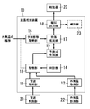
- the room temperature estimation device 10 estimates the room temperature at a target date and time from the outside air temperature, using a prediction formula that relates the outside air temperature to the room temperature. Therefore, the room temperature estimation apparatus 10 has a configuration for obtaining a prediction equation, and a configuration for estimating the room temperature from the outside air temperature using the prediction equation.
- the room temperature estimation apparatus 10 includes, as main hardware elements, a device including a processor that implements the following functions by executing a program and a device for interface.
- a device including a processor a microcomputer including a memory, a processor to which a memory is externally attached, or the like is used.
- a computer that executes a program that implements the following functions is provided as a computer readable recording medium, or provided by communication through a telecommunication line.
- the room temperature estimation device 10 acquires the room temperature acquisition unit 11 that acquires room temperature data (measurement value) from the room temperature measurement unit 21 and the outside air temperature data (measurement value) from the outside air temperature measurement unit 22. And an outside air temperature acquisition unit 12 for acquiring the information.
- the room temperature estimation device 10 stores a storage unit 13 that stores room temperature data (measurement value) and outside air temperature data (measurement value) in association with each measured date and time, and a clock unit 14 that counts time and date.
- a prediction formula generation unit 15 for generating a plurality of prediction formulas respectively corresponding to a plurality of times.
- the room temperature measurement unit 21 is provided inside a predetermined building room, and measures the temperature (room temperature) of the place where the room temperature measurement unit 21 is provided.
- the outside air temperature measurement unit 22 is provided outside the building and measures the temperature (outside air temperature) of the place where the outside air temperature measurement unit 22 is provided.
- the room temperature measurement unit 21 and the outside air temperature measurement unit 22 each include a temperature sensor such as a thermistor that can obtain an analog output according to the ambient temperature, and a sensor amplifier that amplifies the output of the temperature sensor. Further, each of the room temperature measurement unit 21 and the outside air temperature measurement unit 22 transmits, to the room temperature estimation apparatus 10, a conversion unit that converts the output of the sensor amplifier into data of digital values, and data of digital values output from the conversion unit. And a communication unit.
- a temperature sensor such as a thermistor that can obtain an analog output according to the ambient temperature
- a sensor amplifier that amplifies the output of the temperature sensor.
- each of the room temperature measurement unit 21 and the outside air temperature measurement unit 22 transmits, to the room temperature estimation apparatus 10, a conversion unit that converts the output of the sensor amplifier into data of digital values, and data of digital values output from the conversion unit. And a communication unit.
- Each of the room temperature measurement unit 21 and the outside air temperature measurement unit 22 may have a configuration in which the communication unit is omitted, or a configuration in which the conversion unit and the communication unit are omitted.
- a converter and a communication unit are provided for transmission.
- each of the room temperature measurement unit 21 and the outside air temperature measurement unit 22 provides data of an analog value to the room temperature estimation device 10.
- Communication between each of the room temperature measurement unit 21 and the outside air temperature measurement unit 22 and the room temperature estimation device 10 is preferably performed using a wireless communication channel using radio waves as a transmission medium, but a wired communication channel can also be used. is there.
- the room temperature measurement unit 21 may share the housing with the room temperature estimation device 10. When the room temperature measurement unit 21 shares the casing with the room temperature estimation device 10, the communication unit is not necessary for the room temperature measurement unit 21.
- the data (measurement value) of the room temperature acquired by the room temperature acquisition unit 11 and the data (measurement value) of the outside air temperature acquired by the outside air temperature acquisition unit 12 are stored in the storage unit 13 in association with the measured date and time. . That is, the storage unit 13 stores two pairs of (room temperature, date and time) (outside temperature, date and time) or stores three pairs of (room temperature, outside temperature, date and time) as one set. The latter has a smaller amount of data and saves the storage capacity of the storage unit 13.
- the clock unit 14 provided in the room temperature estimation device 10 counts the date and time stored in the storage unit 13.
- dates and times at which data of the room temperature and the outside air temperature are acquired are set in advance.
- the room temperature acquisition unit 11 and the outside air temperature acquisition unit 12 each acquire data of the room temperature and the outside air temperature at a preset date and time using the date and time counted by the clock unit 14. In this case, it is desirable that the storage unit 13 store three of (room temperature, outside temperature, date and time) as one set.
- the room temperature acquisition unit 11 and the outside air temperature acquisition unit 12 acquire data, for example, every hour.
- the room temperature acquisition unit 11 and the outside air temperature acquisition unit 12 acquire data, for example, every hour.
- the time interval at which the room temperature acquisition unit 11 and the outside air temperature acquisition unit 12 acquire data does not have to be every hour, and may be selected as needed from 10 minutes, 15 minutes, 30 minutes, 2 hours, etc. . If the time interval is short, the amount of information increases, and it is considered that a prediction formula with high estimation accuracy can be obtained, but the amount of data stored in the storage unit 13 also increases. Therefore, it is preferable to set a time interval for acquiring data in a range from a fraction of an hour to several times of one hour on the basis of one hour.
- the time interval at which the room temperature acquisition unit 11 and the outside air temperature acquisition unit 12 acquire data is preferably set to a value obtained by dividing 24 hours by an integer value.
- the room temperature measurement unit 21 and the outside air temperature measurement unit 22 may each be provided with a clock unit for measuring the date and time.
- the room temperature measurement unit 21 and the outside air temperature measurement unit 22 transmit, to the room temperature estimation device 10, the data of the room temperature and the outside air temperature acquired on the date and time clocked by each clock unit. That is, the room temperature measurement unit 21 and the outside air temperature measurement unit 22 transmit data of the room temperature and the outside air temperature to the room temperature estimation device 10 in association with the date and time when the respective clock units clock.
- the storage unit 13 store two types of pairs: (room temperature, date and time) (outside temperature, date and time).
- the timing at which the room temperature measurement unit 21 and the outside air temperature measurement unit 22 transmit the data of the room temperature and the outside air temperature does not have to be the date and time when the room temperature and the outside air temperature are measured. It is possible to send together.
- the size of the deviation is not more than half the data acquisition interval (for example, 1/1 of the data acquisition interval). If it is 10 or less), it is desirable that these data be regarded as acquired at the same date and time, and be associated with the same date and time.
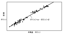
- the inventor measured the room temperature and the outside temperature at a plurality of times for a plurality of relatively long days. Then, as a result of graphing the relationship between the room temperature and the outside air temperature for each time, as shown in FIG. 2, it was found that the outside air temperature and the room temperature become substantially linear at a specific time. That is, it has been found that the room temperature at a specific time can be represented by a prediction equation of a linear function with the outside air temperature as a variable, and the room temperature can be estimated from the outside air temperature using this prediction equation. Specifically, a linear relationship is established between the ambient temperature measured at the first specific time of the plurality of days and the room temperature, and the ambient temperature and the room temperature measured at the second specific time of the plurality of days It has been found that a linear relationship holds between
- the prediction formula generation unit 15 of the room temperature estimation device 10 of the present embodiment generates a prediction formula using the outside air temperature and the room temperature at specific times of a plurality of days.
- the prediction formula generation unit 15 extracts data of room temperature and outside temperature at a specific time for a plurality of days in a predetermined extraction period stored in the storage unit 13, and performs regression from data of room temperature and outside temperature at the same time in a plurality of days An equation is obtained, and this regression equation is used as a prediction equation. That is, prediction equation generation unit 15 uses the data of room temperature and outside air temperature at specific times (same time) of a plurality of days in a predetermined extraction period stored in storage unit 13 to calculate room temperature and outside air temperature for the specific time. Generate a prediction equation that represents the relationship.
- the data of the room temperature and the outside temperature used to generate the regression equation needs three days or more. That is, the extraction period needs to include multiple days of 3 days or more, and for example, it is desirable to select from the range of 15 to 90 days.
- the lower limit of 15 days is the number of days corresponding to one relief (half moon)
- the upper limit of 90 days is the number of days corresponding to one season in spring, summer, autumn, and winter. This number of days is an example, and may be, for example, 30 days (about 1 month), or 1 year if it is a region where the change in the outside temperature is small throughout the year.
- generation of a prediction equation may contain two or more continuous days, and may be two or more non-consecutive days.
- the prediction equation may be generated using data of room temperature and ambient temperature measured every one day, once every two days, once a week, etc. for one to several years.
- the room temperature ⁇ 1 (t) and the outside air temperature ⁇ 2 (t) are fitted to a linear function using a known method such as the least squares method. That is, the prediction formula generation unit 15 obtains the regression prediction formula from the data of the room temperature ⁇ 1 (t) and the outside air temperature ⁇ 2 (t) at the time (specific time) t to which attention is paid in the extraction period.
- the prediction formula generation unit 15 obtains the prediction formula by simple regression analysis with the data of the outside air temperature as the independent variable and the data of the room temperature as the dependent variable.
- the time to find the regression prediction formula (specific time) is a time zone in which the room temperature is not affected by solar radiation and depends only on the outside temperature, and from a time zone in which the change in the outside temperature is relatively moderate. It is selected.
- the prediction formula generation unit 15 uses the regression prediction formula obtained as described above for the prediction formula for obtaining the room temperature from the outside air temperature.
- the prediction formula generation unit 15 obtains regression prediction formulas for a plurality of times. Then, the prediction formula generation unit 15 generates the obtained regression prediction formula as a prediction formula at each time. That is, the prediction formula generation unit 15 generates a plurality of prediction formulas respectively corresponding to a plurality of specific times. Each of the plurality of prediction formulas is obtained using data of room temperature and ambient temperature for the corresponding specific time. Specifically, the prediction formula generation unit 15 generates at least first and second prediction formulas respectively corresponding to at least first and second specific times. The first prediction formula is generated using the data of the room temperature and the outside temperature at the first specific time of each of the plurality of days in the extraction period. The second prediction formula is generated using the data of the room temperature and the ambient temperature at the second specific time of each of the plurality of days in the extraction period.
- the room temperature estimation apparatus 10 generates a plurality of prediction formulas respectively corresponding to a plurality of time points by the method described above, and estimates the room temperature from the outside air temperature using the obtained prediction formulas. That is, the room temperature estimation device 10 generates (at least) the first prediction formula corresponding to the first specific time and the second prediction formula corresponding to the second specific time. Then, the room temperature estimation device 10 uses the first prediction formula when estimating the room temperature of the time corresponding to the first specific time, and the second prediction when estimating the room temperature of the time corresponding to the second specific time. Use the formula.
- the room temperature estimation apparatus 10 generates a first prediction formula using the data of the room temperature and the outside air temperature obtained at 4:00 am (first specific time) of multiple days, and generates the first prediction equation at 5:00 am of multiple days
- the data of the room temperature and the outside air temperature obtained at (second specified time) is used to generate a second prediction equation.
- the room temperature estimation apparatus 10 uses the first prediction formula when estimating the room temperature at 4 am (time corresponding to the first specific time) on a predetermined day, and uses the first prediction formula, at 5 am (second time) on the predetermined day.
- the second prediction equation is used when estimating the room temperature of the time corresponding to the specific time of.
- the room temperature estimation device 10 acquires a predicted transition acquisition unit 16 that acquires a predicted transition of the outside air temperature using a time series of data (measurement values) of the outside air temperature acquired by the outside air temperature acquisition unit 12 from the outside air temperature measurement unit 22 , And a room temperature estimation unit 17 for estimating the room temperature from the transition of the outside air temperature.
- the forecasted transition acquisition unit 16 fits the time series of data of the outside temperature to any of a plurality of templates (templates) of transition of the outside temperature registered in advance, and uses the fitted typical Predict the transition.
- templates templates
- the predicted transition acquiring unit 16 narrows down the examples to be fitted in consideration of the weather and the season of the day.
- the outside air temperature acquisition unit 12 acquires the transition of the outside air temperature through a telecommunication line such as the Internet. It is also good. That is, the outside air temperature acquisition unit 12 has a function of acquiring data of the outside air temperature from the service provider who provides the information of the weather for each region through the telecommunication line. When adopting this configuration, the predicted transition acquisition unit 16 uses data of the outside air temperature acquired by the outside air temperature acquisition unit 12 from the service provider.
- the data on the outside air temperature provided through the telecommunication line is data on a specific point in the area where the room for which the room temperature is to be estimated exists, and is not the outside air temperature for the room. It is expected that the temperature is in a linear relationship. Therefore, if the room temperature estimation unit 17 calibrates the room temperature estimated from the data of the outside air temperature based on the measured value of the room temperature, it can estimate the room temperature using the data of the outside air temperature acquired through the telecommunication line It is.
- the room temperature estimation unit 17 uses the predicted transition of the outside air temperature acquired by the predicted transition acquisition unit 16 to obtain the outside air temperature at the time of interest.
- the room temperature estimation unit 17 estimates the room temperature by fitting the determined outside air temperature to the prediction equation generated by the prediction equation generation unit 15. That is, the room temperature estimation unit 17 obtains the outside air temperature obtained for the date and time when the room temperature is to be estimated using the predicted transition of the outside air temperature, and applies the outside air temperature to the prediction equation to obtain Estimate the room temperature.
- the room temperature estimation device 10 includes a notification output unit 18 that outputs the room temperature estimated by the room temperature estimation unit 17 to the annunciator 23.
- the annunciator 23 may be a device including a display device such as a smartphone, a tablet terminal, or a personal computer, as well as a dedicated device including a display device, and a communication function. When these devices are used as the annunciator 23, the notification output unit 18 is configured to communicate with these devices.
- the annunciator 23 may be integrally provided in the housing of the room temperature estimation device 10, like the annunciator 23 indicated by a broken line in FIG.
- the room temperature estimated by the room temperature estimation unit 17 is not only notified to the user by the annunciator 23, but is also a device that affects the room temperature, such as a ventilation fan, an air conditioner, an electric shutter, an electric curtain, and an electric window. You may use for control.
- a heating and cooling device for example, air conditioner
- if room temperature is estimated based on the transition of the outside air temperature it becomes possible to appropriately determine the timing for stopping the operation of the heating and cooling device. It is possible to reduce the energy consumed for heating and cooling.
- the time to stop the operation of the cooling system can be determined. Energy saving can be achieved by preventing such driving.
- the time for stopping the operation of the room heat system is determined. It is possible to save energy by preventing unnecessary operation.
- the relational expression representing the relationship between the outside air temperature and the room temperature will change depending on the season.
- the left side shows the relationship between room temperature and outside temperature in winter
- the right side shows the relationship between room temperature and outside temperature in summer.
- the left group and the right group are the same. It looks like it can be represented by a linear function.
- FIG. 3 when the left group (the group plotted with squares in FIG. 3) and the right group (the group plotted with triangles in FIG. 3) are respectively applied to linear functions, Different prediction formulas (each shown by a straight line) are obtained.
- the extraction period is set for each division period set by dividing one year into a plurality.
- Division period is period (the period which divided 1 year on the basis of the meteorological environment) which divided 1 year into 4 to 24 division (a unit of 4 division is a unit reflecting spring, summer and winter and 24 division is a unit of half a month). It is desirable to select appropriately.
- the number of days of the division period is 15 to 90 days, and the extraction period may be 3 days or more for each division period.
- the extraction period and the division period are stored, for example, in the storage unit 13 in advance.
- the prediction formula generation unit 15 generates a plurality of prediction formulas in accordance with the number of division periods. That is, the prediction formula generation unit 15 generates a plurality of prediction formulas respectively corresponding to a plurality of times for each division period. Then, when estimating the room temperature at a predetermined date and time, the room temperature estimation unit 17 selects a prediction formula generated for the target time in the division period to which the target day belongs, from the plurality of prediction expressions obtained for each division period. Estimate the room temperature from the transition of the outside temperature using the selected prediction formula.
- the room temperature estimation unit 17 estimates the room temperature using the newly generated prediction equation.
- the prediction equation generation unit 15 since the prediction equation generation unit 15 generates the prediction equation using the room temperature and the outside air temperature in a time zone in which the room temperature is not affected by solar radiation, the room temperature is estimated from the outside air temperature using the prediction equation. There is a limit to the time that can be done. That is, during the time zone in which the room temperature is affected by solar radiation, the room temperature can not be accurately estimated by the prediction equation obtained in the first embodiment, and the prediction equation obtained in the first embodiment As such, it can be adopted only in the time zone where the change of the outside air temperature is relatively small.
- the present embodiment describes a technique for setting a prediction formula that can be used in a daytime time zone in which room temperature is affected by solar radiation. Therefore, the prediction equation obtained by the technique of the first embodiment is adopted in a time zone where it is not necessary to consider the influence of solar radiation at night, and in the time zone where the influence of solar radiation is considered in the daytime, the prediction described below The formula is adopted. That is, this embodiment adopts a configuration in which the type of prediction equation is changed between a time zone in which solar radiation does not affect room temperature (a time zone in which solar radiation does not occur) and a time zone in which solar radiation affects room temperature.
- the prediction formula generation unit 15 in the room temperature estimation device 10 of the present embodiment has a function of generating two types of prediction formulas.
- the room temperature estimation apparatus 10 will be described below with a first prediction formula generation unit 151 that generates a prediction formula (first kind of prediction formula) using the same technology as that of the first embodiment. And a second prediction formula generation unit 152 that generates a prediction formula (a second type of prediction formula) by a technology.
- the first prediction formula generation unit 151 generates a prediction formula in the same manner as the prediction formula generation unit 15 in the first embodiment.
- the first prediction formula generation unit 151 generates a regression prediction formula using data of room temperature and ambient temperature at specific times of a plurality of days stored in the storage unit 13, and uses the generated regression prediction formula as a prediction formula .
- the second prediction formula generation unit 152 considers that the relationship between the room temperature and the outside air temperature depends on the thermal characteristics of the room (heat insulation, heat storage property, etc.), and the prediction formula is Generate Now, assuming that the room temperature depends only on the outside air temperature, a model is assumed in which heat is conducted through partitions consisting of a wall, a ceiling, and a floor surrounding the room, and the room temperature changes following the outside air temperature. According to this model, the influence of the outside air temperature on the room temperature is considered to change depending on the degree of heat conduction of the partitions and the degree of heat storage of the partitions. However, room temperature is taken as the temperature of the air in a room, without considering the radiant heat from a partition.
- the inventor of the present invention has a correlation between the change in the outside air temperature and the change in the room temperature, and the room temperature is a delay time according to the heat characteristics of the partition (heat insulation, heat storage property, etc.). We find that it is delayed and changes. In addition, if this delay time can be determined, the relationship between the room temperature at a specific time and the outside air temperature at a time shifted from the specific time by the delay time can be expressed by a simple prediction equation. It has been found that the room temperature can be estimated from the outside air temperature.
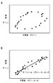
- the graph which plotted the relationship of the room temperature and external temperature which were measured on the same date and time is shown to FIG. 5A. Just looking at the illustrated example, it is not possible to find a relationship between room temperature and ambient temperature. On the other hand, as described above, the present embodiment is based on the assumption that the change in the outside air temperature and the change in the room temperature are correlated with a delay time corresponding to the thermal characteristic of the room.
- the room temperature estimation apparatus 10 uses the data of the room temperature (measurement value), the data of the outside air temperature (measurement value), and the date and time stored in the storage unit 13 to determine the phase relationship between the room temperature and the outside air temperature.
- An evaluation unit 19 is provided for obtaining a delay time at which the number is maximized.
- the evaluation unit 19 shifts the date and time when the room temperature was measured and the date and time when the outside temperature was measured relative to the data of the room temperature and the data of the outside air temperature on a predetermined day (referred to as “extraction day”)
- extraction day a predetermined day
- the extraction date is not limited to one day, and may be multiple days.
- the following describes an example of shifting the date and time when the outside air temperature was measured based on the date and time when the room temperature was measured, but the date and time when the room temperature was measured based on the date and time when the outside air temperature was measured are shifted You may
- t0 is a reference value given according to the extraction date, and m and n are natural numbers.
- data of room temperature are expressed as ⁇ 1 (t0 + p), ⁇ 1 (t0 + 2p), ⁇ 1 (t0 + 3p), ..., and data of outside temperature are ⁇ 2 (t0 + p), ⁇ 2 (t0 + 2p), ⁇ 2 It is expressed as (t0 + 3p),.
- the average value a ( ⁇ 1) of the room temperature ⁇ 1 (t) in the extraction date period is ⁇ 1 (t0 + p), ⁇ 1 (t0 + 2p), ..., ⁇ 1 (t0 + q)
- the average value of p) ⁇ is an average value.
- [T0 + p, t0 + q ⁇ p] is a closed section and represents q discrete values of ⁇ t0 + p, t0 + 2p, t0 + 3p,..., T0 + q ⁇ p ⁇ .
- the calculation of the correlation coefficient is a generally known operation, and the covariance of ⁇ 1 (t) and ⁇ 2 (t- ⁇ t) is calculated by the standard deviation of ⁇ 1 (t) and the standard deviation of ⁇ 2 (t- ⁇ t) It is obtained by dividing by the product of However, as the average values a ( ⁇ 1) and a ( ⁇ 2) for obtaining the covariance and the standard deviation, the values described above are used.
- the range of the date and time t in the room temperature data ⁇ 1 (t) and the outside air temperature data ⁇ 2 (t ⁇ t) uses the period of the extraction date (closed interval [t0 + p, t0 + q ⁇ p]).
- the evaluation unit 19 changes the time difference ⁇ t by changing the value of m, and obtains a correlation coefficient for each value of m.
- the maximum value of m is limited so that the product m ⁇ p with the time interval p does not exceed one day. For example, if the time interval p is one hour, the maximum value of m is limited not to exceed 24.
- the relationship between the room temperature ⁇ 1 (t) and the outside air temperature ⁇ 2 (t- ⁇ t A ) is plotted as shown in FIG. 5B using the time difference (optimum time difference) ⁇ t A calculated by the evaluation unit 19 as described above.
- the room temperature ⁇ 1 (t) and the outside air temperature ⁇ 2 (t ⁇ t A ) have a substantially linear relationship, and it can be seen that the linear function can be fitted.
- the second prediction formula generation unit 152 generates a prediction formula for estimating the room temperature from the outside air temperature, using the relationship shown in FIG. 5B.
- the second prediction formula generation unit 152 extracts the data of the extraction date from the data of the room temperature and the data of the outside air temperature stored in the storage unit 13, and the evaluation unit 19 at the date and time corresponding to the extracted data of the outside air temperature.
- the coefficients ⁇ and ⁇ are determined by a well-known operation such as the method of least squares, expressed in the form of ⁇ t A ) + ⁇ .
- the second prediction formula generation unit 152 obtains the prediction formula by single regression analysis using the data of the outside air temperature after giving the time difference ⁇ t A as an independent variable and the data of room temperature as a dependent variable.
- the evaluation unit 19 obtains the time difference ⁇ t A and the second prediction equation generation unit 152 determines the coefficients ⁇ and ⁇ , whereby the prediction equation (the second type of prediction equation) is obtained.
- the coefficients ⁇ and ⁇ usually have different values from the coefficients ⁇ and ⁇ included in the prediction equation generated by the first prediction equation generation unit 151.
- the second prediction formula generation unit 152 determines the time difference (optimum time difference) by using the data of the room temperature and the outside air temperature on the predetermined extraction date stored in the storage unit 13 and gives this time difference.
- the prediction formula is generated from the data of the room temperature and the data of the outside air temperature.
- the prediction equation generated by the second prediction equation generation unit 152 can be applied regardless of whether the room temperature is affected by solar radiation. In addition, it is possible to estimate room temperature using one prediction equation regardless of time. However, if the room temperature is a time zone not affected by solar radiation, the second prediction formula can be obtained with relatively good accuracy by the prediction formula (first kind of prediction formula) generated by the first prediction formula generation unit 151. It is possible to estimate the room temperature from the outside air temperature (with higher accuracy than the prediction equation of the generation unit 152).
- the prediction equation generated by the first prediction equation generation unit 151 is adopted in the time period where the room temperature can be predicted by the prediction equation generated by the first prediction equation generation unit 151, and in the other time periods. It is desirable to share roles so as to use the prediction formula generated by the second prediction formula generation unit 152. That is, the prediction equation (first kind of prediction equation) generated by the first prediction equation generation unit 151 is adopted in a time zone in which the room temperature is not affected by solar radiation (a time zone in which there is no solar radiation). The prediction equation (the second type of prediction equation) generated by the second prediction equation generation unit 152 is adopted as the time zone affected.
- the room temperature estimation device 10 estimates the room temperature from the outside air temperature using the prediction equation generated by the second prediction equation generation unit 152, the time difference (delay time) ⁇ t calculated by the evaluation unit 19 with respect to the date and time of interest It is necessary to acquire the data of the outside temperature at the date and time that went back by A.
- the time of interest means the time of day when it is intended to estimate the room temperature.
- the room temperature estimation unit 17 uses the predicted transition of the outside air temperature acquired by the predicted transition acquisition unit 16 and the time difference (optimum time difference) calculated by the evaluation unit 19 and dates back to the time of interest by the time difference Determine the ambient temperature (actual or predicted value) of
- the room temperature estimation unit 17 estimates the room temperature by fitting the determined outside air temperature to the prediction equation generated by the prediction equation generation unit 15. That is, the room temperature estimation unit 17 obtains the outside temperature at the time when the evaluation unit 19 goes back by the time difference calculated from the date and time to estimate the room temperature using the predicted transition of the outside temperature, and predicts this outside temperature. By applying the equation, the room temperature of the date and time of interest is estimated.
- the prediction formula generation unit 15 of the present embodiment includes a first prediction formula generation unit 151 and a second prediction formula generation unit 152.
- the room temperature estimation unit 17 determines whether the room temperature is not affected by solar radiation or the room temperature is affected by solar radiation, according to the date and time kept by the clock unit 14.
- the prediction equation generated by the first prediction equation generation unit 151 is adopted in a time zone in which the room temperature is not affected by solar radiation, and in the time zone in which the room temperature is affected by solar radiation, the second prediction equation generation unit 152
- the prediction equation generated by is adopted.
- the prediction formulas generated by the second prediction formula generation unit 152 are also easily expected to change depending on the season. Therefore, it is desirable to set the extraction date for measuring the room temperature and the outside air temperature used to generate the prediction formula for each season.
- a divided period in which one year is divided into plural is set, and an extraction date is determined for each divided period.
- the division period is appropriately selected from the period in which 1 year is divided into 4 to 24 divisions (4 division is a unit reflecting spring, summer, and winter, and 24 division is a unit with half a month as a unit).
- the second prediction formula generation unit 152 generates a number of prediction formulas corresponding to the number of division periods. Further, the room temperature estimation unit 17 selects the prediction formula generated for the division period to which the target date and time belongs from the plurality of prediction formulas obtained for each division period, and changes the outside temperature using the selected prediction formula Estimate
- the room temperature estimation unit 17 estimates the room temperature. That is, the evaluation unit 19 newly obtains a time difference (optimum time difference) ⁇ t A each time the division period elapses, and the second prediction formula generation unit 152 generates a prediction formula (second type) corresponding to the obtained time difference ⁇ t A It is desirable that the prediction equation be newly generated, and the room temperature estimation unit 17 estimate the room temperature using the newly generated prediction equation (the second type of prediction equation). However, the room temperature estimation unit 17 can estimate the room temperature using the time difference obtained in any of the divided periods. In addition, it is possible to estimate the room temperature using an average value of time differences obtained in a plurality of division periods.
- the room temperature estimation unit 17 uses different types of prediction formulas depending on whether or not the room temperature is affected by solar radiation, the outside air temperature to be substituted into the prediction formulas is also different. Compared with the configuration of the first embodiment, the prediction accuracy of the room temperature can be enhanced. Other configurations and operations are the same as in the first embodiment.
- the room temperature estimation device 10 estimates the room temperature only by the outside air temperature, but as described above, the factors determining the room temperature are solar radiation, ventilation, rainfall, when air conditioning is not performed. Including the number of people in the room.
- the room temperature depends on the operating state of the heating and cooling system, and the room temperature can not be predicted by the prediction formula. We do not consider about
- this embodiment uses these pieces of information as correction information, limits the number of states that each correction information can take, and sets prediction formulas for each state of correction information, thereby increasing the number of parameters and the processing load. To prevent. That is, when using a plurality of correction information, the prediction formula generation unit 15 divides the state into a plurality of stages for each correction information, and generates a prediction formula (corrected prediction formula) associated with a combination of these stages.
- the prediction formula generation unit 15 divides the state into a plurality of stages for each correction information, and generates a prediction formula (corrected prediction formula) associated with a combination of these stages.
- each state is divided into two stages of only presence or absence, and it is considered that the number of persons is raised by a predetermined temperature (for example, 0.5 ° C.) per person.
- a predetermined temperature for example, 0.5 ° C.
- the prediction formula generation unit 15 sets a prediction formula in accordance with a combination of individual states of correction information. Since the number of people in the room is reflected only on the coefficient ⁇ of the prediction equation, it is not necessary to generate a prediction equation for each person, and the room temperature estimation unit 17 doubles the number of people at a predetermined temperature to the room temperature obtained from the prediction equation. Correction to add. Therefore, in the above example, eight prediction equations are generated from the correction information of solar radiation, ventilation, and rainfall.
- the prediction equation generation unit 15 generates a corrected prediction equation by correcting the coefficients ⁇ and ⁇ of the prediction equation according to the state of the correction information.
- the storage unit 13 stores correction amounts of the coefficients ⁇ and ⁇ according to the state of each correction information.
- the prediction equation generation unit 15 reads out the correction amount of the coefficients ⁇ and ⁇ corresponding to this state from the storage unit 13 when certain correction information is in the one state (for example, the state with ventilation), and reads the correction By applying the quantities to the coefficients ⁇ , ⁇ of the prediction equation, a corrected prediction equation is generated.
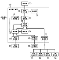
- the room temperature estimation apparatus 10 of the present embodiment further includes a correction information acquisition unit 32 that acquires correction information from the solar radiation detection unit 33, the ventilation detection unit 34, the rainfall detection unit 35, and the number detection unit 36, as shown in FIG. .
- the solar radiation detection unit 33 may include a light receiving element such as a photodiode or a phototransistor, and a determination unit that determines the light amount by comparing the output of the light receiving element with a threshold. Further, since the influence of solar radiation on the room also depends on the open / close state of the curtain or shutter, it is preferable that the solar radiation detection unit 33 has a function of detecting the open / close state of the curtain or shutter.
- the ventilation detection unit 34 is selected from a configuration that detects whether the ventilation fan is operating, a configuration that detects the open / close state of the window, a configuration that measures the airflow in the room, and the like.
- the rainfall detection unit 35 adopts a configuration in which raindrops are collected to measure a mass every predetermined period, or a configuration in which raindrops are detected from an image outdoors. Also, correction information on rainfall may be obtained by information provided by a service provider through a telecommunication line such as the Internet.
- the number detection unit 36 adopts a configuration that measures the number of people in the room from the image in the room.
- solar radiation can be divided into four stages: strong, moderate, weak, and weak.
- the room temperature estimation unit 17 corrects the prediction formula based on the correction information acquired by the correction information acquisition unit 32, generates a correction prediction formula, and estimates the room temperature from the outside air temperature using the correction prediction formula.
- the correction amounts of the coefficients ⁇ and ⁇ according to solar radiation, ventilation, rainfall, and the number of persons are statistically determined based on the measured values.
- Other configurations and operations are the same as in the first and second embodiments.
Landscapes
- Engineering & Computer Science (AREA)
- Chemical & Material Sciences (AREA)
- Combustion & Propulsion (AREA)
- Mechanical Engineering (AREA)
- General Engineering & Computer Science (AREA)
- Physics & Mathematics (AREA)
- Fuzzy Systems (AREA)
- Mathematical Physics (AREA)
- Signal Processing (AREA)
- Life Sciences & Earth Sciences (AREA)
- Atmospheric Sciences (AREA)
- Air Conditioning Control Device (AREA)
Abstract
室温推定装置(10)は、記憶部(13)、予測式生成部(15)、予測推移取得部(16)、室温推定部(17)を備える。予測式生成部(15)は、記憶部(13)に格納された所定の抽出期間における複数日の特定時刻における室温および外気温のデータを用いて、当該特定時刻に対する室温と外気温との関係を表す予測式を生成する。室温推定部(17)は、予測推移取得部(16)が取得した外気温の推移を用いて、上記特定時刻に対応する着目日時の外気温を求め、予測式に外気温を当て嵌めることにより、当該着目日時の室温を推定する。
Description
本発明は、着目する日時の室温を予測する室温推定装置、およびコンピュータを室温推定装置として機能させるプログラムに関する。
従来から、室温の推移と予測される外気温とを用いることにより、予定時刻に室温を希望の設定温度にする技術が知られている(たとえば、日本国特許出願公開平6-42765号公報参照、以下“文献1”と称する)。また、車両の室温に関して、推定した日射量の変化と、計測した外気温および室温とから室温の変化を予測し、室温が所定の閾値に達することが予測される場合に通知する技術が知られている(たとえば、日本国特許出願公開2005-343386号公報参照、以下“文献2”と称する)。
文献1には、計測される環境の情報が室温であって、計測された室温の履歴に基づいて室温の変化を予測する技術が記載されている。さらに、文献1では、予測される室温および外気温の変化と、室内暖房に必要な熱量(暖房負荷熱量)および暖房装置の暖房能力とから、暖房装置の運転開始時刻および暖房開始時刻が定められている。すなわち、文献1では、室温と外気温との予測値が求められ、予測値に基づいて、室温を希望する設定温度にするための暖房負荷熱量が求められている。
文献1に記載された構成は、暖房負荷熱量を求めるために、室温を予測する。しかしながら、文献1では、室温の予測は履歴に基づいており、室温を定める他の要因を用いて室温を予測する技術は記載されていない。
文献2には、計測される環境の情報が室温および外気温であって、計測された室温および外気温と併せて予測される日射量を用いることにより、車室内の温度を予測する技術が記載されている。
文献2に記載された構成は、車室内の温度を予測する技術であり、車室内の温度は外気温の変化に短時間で追従するから、外気温および日射量とから車室内の温度を予測することは比較的容易である。しかしながら、建物の部屋の温度は、外気温が変化してもただちに変化することはなく、部屋の断熱性能のような熱特性に依存するから、文献2に記載された技術を用いて、建物の室温を外気温から予測することは困難である。
一方、建物の室温を、外気温、建物の断熱性能、日射、換気、降雨、人の存否などの種々の要因から求めるために、コンピュータシミュレーションを行う技術が知られている。しかしながら、この種のコンピュータシミュレーションを行うには、多数の情報が必要である上に、正確な値を得るために別の計測が必要になる情報が含まれることがあるから、室温の予測のために簡便に用いることはできない。
本発明は、計測された環境の情報に基づいて、複雑なコンピュータシミュレーションを行うことなく建物内の部屋の室温を推定する室温推定装置を提供することを目的とし、さらに、コンピュータを室温推定装置として機能させるプログラムを提供することを目的とする。
本発明に係る室温推定装置は、室温計測部から室温のデータを取得する室温取得部と、外気温計測部から外気温のデータを取得する外気温取得部と、前記室温取得部が取得した室温のデータおよび前記外気温取得部が取得した外気温のデータをそれぞれが計測された日時に対応付けて格納する記憶部と、前記記憶部に格納された所定の抽出期間における複数日の各々の特定時刻における室温および外気温のデータを用いて、当該特定時刻に対する室温と外気温との関係を表す予測式を生成する予測式生成部と、外気温について予測される推移を取得する予測推移取得部と、前記予測推移取得部が取得した外気温の推移を用いて、前記特定時刻に対応する着目時刻の外気温を前記予測式に当て嵌めることにより、当該着目時刻における室温を推定する室温推定部とを備えることを特徴とする。
この室温推定装置において、前記予測式生成部は、少なくとも第1および第2の特定時刻にそれぞれ対応する少なくとも第1および第2の予測式を前記予測式として生成し、前記第1の予測式は、前記抽出期間における複数日の各々の第1の特定時刻における室温および外気温のデータを用いて生成され、前記第2の予測式は、前記抽出期間における複数日の各々の第2の特定時刻における室温および外気温のデータを用いて生成され、前記室温推定部は、前記第1の特定時刻に対応する第1の着目時刻の外気温を前記第1の予測式に当て嵌めることにより、当該第1の着目時刻における室温を推定し、前記第2の特定時刻に対応する第2の着目時刻の外気温を前記第2の予測式に当て嵌めることにより、当該第2の着目時刻における室温を推定することが好ましい。
この室温推定装置において、前記予測式生成部は、室温のデータと外気温のデータとから回帰式を求め、この回帰式を前記予測式として生成することが好ましい。
この室温推定装置において、前記予測式生成部は、前記外気温のデータを独立変数とし、前記室温のデータを従属変数とする単回帰分析により、前記予測式を生成することが好ましい。
この室温推定装置において、前記抽出期間は、気象環境に基づいて1年を複数に区分した分割期間ごとに定められ、前記室温推定部は、所定の分割期間における室温の予測に、当該分割期間に対して定めた前記抽出期間における室温および外気温のデータを用いて生成した前記予測式を適用することが望ましい。
この室温推定装置において、外気温のほかに室温に影響を与え、かつ複数の状態から選択される補正情報を取得する補正情報取得部をさらに備え、前記前記予測式生成部は、前記補正情報取得部が取得した前記補正情報の状態に応じて前記予測式を補正することにより補正予測式を生成し、前記室温推定部は、前記補正予測式を用いて室温を推定することが好ましい。
この室温推定装置において、前記室温推定部が推定した室温を報知器に出力する報知出力部をさらに備えることが好ましい。
この室温推定装置において、前記外気温取得部は、電気通信回線を通して提供される外気温のデータを取得することが好ましい。
本発明に係るプログラムは、コンピュータを、上述したいずれかの室温推定装置として機能させるためのものである。
本発明の構成によれば、複雑なコンピュータシミュレーションを行うことなく、容易に計測可能な情報のみで建物内の部屋の室温を推定することが可能になるという利点を有する。
以下では、予測された外気温の推移を用いることにより、室内の冷暖房を行わない場合の室温を推定する技術について説明する。冷暖房を行わない状態において、室温を定める要因は、外気温、部屋の断熱性能、日射(日射の有無および日射量)、換気(換気の有無および換気量)、降雨(降雨の有無および降雨量)、室内の人数などである。
部屋の断熱性能は、住宅に固有の特性であって、住宅の工法や住宅に使用されている建材などから目安は得られるが、定量的に計測することは容易ではない。また、室内の人数は計測できるが、個々人の代謝量や着衣量によって室温を上昇させる程度は一定ではないから、室温に対する人数の関係を理論的に求めることは容易ではない。同様に、日射、換気、降雨は、監視可能であるが、室温への影響を理論的に求めることは容易ではない。
要するに、室温を定める要因を計測することは可能であるが、これらの要因と室温とを結びつける適切なモデルを作成することは容易ではない。したがって、これらの要因についての計測値からコンピュータシミュレーションによって室温を求めることは容易ではない。また、コンピュータシミュレーションで室温を推定する場合、必要程度の精度を得るためには、入力すべき情報が非常に多い上に補正が必要であって、部屋ごとに室温を推定するには専門家による多大な労力を必要とする。
以下では、複雑なモデルを用いたコンピュータシミュレーションを行うことなく、容易に計測できる情報から室温を比較的よい精度で推定可能な室温推定装置について説明する。実施形態1では、室温を外気温のみにより推定する技術について説明する。実施形態2では、外気温に基づき、部屋の断熱性能を考慮して室温を推定する技術について説明する。また、実施形態3では、日射、換気、降雨、室内の人数を考慮して室温を推定する技術について説明する。
(実施形態1)
本実施形態の室温推定装置10は、外気温と室温とを関係付ける予測式を用いて、着目する日時における室温を外気温から推定する。そのため、室温推定装置10は、予測式を求める構成と、予測式を用いて外気温から室温を推定する構成とを備える。
本実施形態の室温推定装置10は、外気温と室温とを関係付ける予測式を用いて、着目する日時における室温を外気温から推定する。そのため、室温推定装置10は、予測式を求める構成と、予測式を用いて外気温から室温を推定する構成とを備える。
この室温推定装置10は、プログラムを実行することにより以下の機能を実現するプロセッサを備えたデバイスと、インターフェイス用のデバイスとを主なハードウェア要素として備える。プロセッサを備えるデバイスは、メモリを内蔵するマイコン、メモリが外付されるプロセッサなどが用いられる。また、以下の機能を実現するプログラムを実行するコンピュータを、室温推定装置10として機能させることが可能である。この種のプログラムは、コンピュータで読取可能な記録媒体として提供されるか、あるいは電気通信回線を通して通信により提供される。
まず、室温推定装置10において、予測式を求める構成について説明する。予測式を求めるには、室温と外気温とを日時に対応付けて計測する必要がある。そのため、室温推定装置10は、図1に示すように、室温計測部21から室温のデータ(計測値)を取得する室温取得部11と、外気温計測部22から外気温のデータ(計測値)を取得する外気温取得部12とを備える。また、室温推定装置10は、室温のデータ(計測値)および外気温のデータ(計測値)をそれぞれが計測された日時に対応付けて格納する記憶部13と、日時を計時する時計部14と、複数の時刻にそれぞれ対応する複数の予測式を生成する予測式生成部15とを備える。
室温計測部21は、所定の建物の部屋の内部に設けられ、室温計測部21が設けられた場所の温度(室温)を計測する。外気温計測部22は、建物の外部に設けられ、外気温計測部22が設けられた場所の温度(外気温)を計測する。
室温計測部21および外気温計測部22は、サーミスタのように周囲温度に応じたアナログ出力が得られる温度センサと、温度センサの出力を増幅するセンサアンプとをそれぞれ備える。また、室温計測部21および外気温計測部22の各々は、センサアンプの出力をデジタル値のデータに変換する変換部と、変換部から出力されるデジタル値のデータを室温推定装置10に送信する通信部とを備える。
室温計測部21および外気温計測部22の各々は、通信部が省略された構成、あるいは変換部および通信部が省略された構成であってもよいが、室温推定装置10に計測値を正確に伝送するために、変換部および通信部を備えていることが望ましい。なお、変換部が省略されている場合、室温計測部21および外気温計測部22の各々は、アナログ値のデータを室温推定装置10に与えることになる。
室温計測部21および外気温計測部22の各々と室温推定装置10との間の通信は、電波を伝送媒体に用いた無線通信路を用いることが望ましいが、有線通信路を用いることも可能である。また、室温計測部21は、室温推定装置10と筐体を共用してもよい。室温計測部21が室温推定装置10と筐体を共用する場合、室温計測部21に通信部は不要である。
室温取得部11が取得した室温のデータ(計測値)および外気温取得部12が取得した外気温のデータ(計測値)は、それぞれが計測された日時に対応付けて記憶部13に格納される。すなわち、記憶部13は、(室温,日時)(外気温,日時)という2種類の対を記憶するか、(室温,外気温,日時)の3つを一組として記憶する。後者のほうがデータ量は少なく、記憶部13の記憶容量の節約になる。
記憶部13に格納される日時は、室温推定装置10に設けられた時計部14が計時する。室温取得部11および外気温取得部12には、室温および外気温のデータを取得する日時があらかじめ設定されている。室温取得部11および外気温取得部12はそれぞれ、時計部14が計時する日時を用いて、あらかじめ設定された日時に室温及び外気温のデータを取得する。この場合、記憶部13は、(室温,外気温,日時)の3つを一組として記憶することが望ましい。
室温取得部11および外気温取得部12は、たとえば1時間ごとにデータを取得する。室温取得部11および外気温取得部12は、たとえば毎正時にデータを取得する。ただし、室温取得部11および外気温取得部12がデータを取得する時間間隔は、1時間ごとである必要はなく、10分、15分、30分、2時間などから必要に応じて選択される。時間間隔が短いと情報量が多くなり、推定精度の高い予測式が得られると考えられるが、記憶部13に格納するデータの量も増加する。そのため、データを取得する時間間隔は、1時間を基準として、1時間の数分の1から数倍程度の範囲で設定することが好ましい。室温取得部11および外気温取得部12がデータを取得する時間間隔は、24時間を整数値で割って得られる値に設定されていることが好ましい。
なお、室温計測部21および外気温計測部22に、それぞれ日時を計時する時計部が設けられていてもよい。この場合、室温計測部21および外気温計測部22が、それぞれの時計部が計時している日時に取得した室温および外気温のデータを室温推定装置10に対して送信する。すなわち、室温計測部21および外気温計測部22は、それぞれの時計部が計時している日時に、室温および外気温のデータを対応付けて室温推定装置10に送信する。
この構成では、記憶部13は、(室温,日時)(外気温,日時)という2種類の対を記憶することが望ましい。ここに、室温計測部21および外気温計測部22が室温および外気温のデータを送信するタイミングは、室温および外気温を計測した日時である必要はなく、たとえば半日分あるいは1日分のデータをまとめて送信することが可能である。
なお、室温のデータを取得した日時と外気温のデータを取得した日時との間にずれがある場合でも、そのずれの大きさが、データ取得間隔の半分以下(例えば、データ取得間隔の1/10以下)であれば、これらのデータは同じ日時に取得されたとみなして同一の日時に対応付けられることが望ましい。
ところで、室温が日射の影響を受けない状態が継続し、かつ外気温の変化が少ない場合には、部屋に流入する熱量と部屋から流出する熱量とがほぼ平衡状態になり、同時刻における外気温と室温とがほぼ線形関係になるという仮説が得られる。
本発明者は、比較的長期にわたる複数日について、複数の時刻における室温と外気温とを計測した。そして、室温と外気温との関係を時刻ごとにグラフ化した結果、図2に示すように、特定の時刻では、外気温と室温とがほぼ線形関係になるという知見を得た。すなわち、特定の時刻における室温は、外気温を変数とする一次関数の予測式で表すことができ、この予測式を用いて外気温から室温を推定できることを見出した。具体的には、複数日の第1の特定時刻に計測された外気温と室温との間には線形関係が成り立ち、また、複数日の第2の特定時刻に計測された外気温と室温との間には線形関係が成り立つことが、見出された。
そこで、本実施形態の室温推定装置10の予測式生成部15は、複数日の特定の時刻における外気温と室温とを用いて、予測式を生成する。予測式生成部15は、記憶部13に格納された所定の抽出期間における複数日について特定の時刻の室温および外気温のデータを抽出し、複数日における同時刻の室温および外気温のデータから回帰式を求め、この回帰式を予測式として用いる。すなわち予測式生成部15は、記憶部13に格納された所定の抽出期間における複数日の特定時刻(同時刻)における室温および外気温のデータを用いて、当該特定時刻に対する室温と外気温との関係を表す予測式を生成する。
予測式は、外気温の一次関数であることが予測されているから、回帰式を生成するために用いる室温および外気温のデータは、3日分以上が必要である。つまり、抽出期間は3日以上の複数日を含む必要があり、たとえば、15~90日分の範囲から選択することが望ましい。下限の15日は1つの節気(半月)に相当する日数であり、上限の90日は春夏秋冬における1つの季節に相当する日数である。なお、この日数は一例であって、たとえば30日(約1ヶ月)であってもよいし、一年を通じて外気温の変動が少ない地域であれば、1年であってもよい。また、予測式の生成に用いるデータの取得日は、連続する複数日を含んでいてもよいし、連続しない複数日であってもよい。たとえば、1~数年間について1日毎、2日に1回、1週間に1回などに計測した室温および外気温のデータを用いて予測式を生成してもよい。
予測式生成部15は、抽出期間において着目する時刻tの室温θ1(t)および外気温θ2(t)の間に線形関係が成立することを利用し、θ1(t)=α・θ2(t)+βという形式の予測式を生成する。予測式の生成に際して、最小二乗法のような周知の方法を用いて室温θ1(t)と外気温θ2(t)とを一次関数に当て嵌める。すなわち、予測式生成部15は、抽出期間において着目する時刻(特定時刻)tの室温θ1(t)および外気温θ2(t)のデータから回帰予測式を求める。
この回帰予測式は、当該時刻の外気温を説明変数とし、当該時刻における室温を従属変数とする。すなわち、予測式生成部15は、外気温のデータを独立変数とし、室温のデータを従属変数とする単回帰分析により、予測式を求める。ただし、回帰予測式を求める時刻(特定時刻)は、室温が日射の影響を受けずに、外気温にのみ依存する時間帯であって、かつ外気温の変動が比較的緩やかである時間帯から選択される。予測式生成部15は、上述のようにして求めた回帰予測式を、外気温から室温を求める予測式に用いる。
また、予測式生成部15は、複数の時刻について回帰予測式をそれぞれ求める。そして予測式生成部15は、得られた回帰予測式を、各時刻における予測式として生成する。すなわち、予測式生成部15は、複数の特定時刻にそれぞれ対応する複数の予測式を生成する。複数の予測式の各々は、対応する特定時刻に対する室温および外気温のデータを用いて求められる。具体的には、予測式生成部15は、少なくとも第1および第2の特定時刻にそれぞれ対応する少なくとも第1および第2の予測式を生成する。第1の予測式は、抽出期間における複数日の各々の第1の特定時刻における室温および外気温のデータを用いて生成される。第2の予測式は、抽出期間における複数日の各々の第2の特定時刻における室温および外気温のデータを用いて生成される。
室温推定装置10は、上述した方法で、複数の時刻にそれぞれ対応する複数の予測式を生成し、求めた予測式を用いて外気温から室温を推定する。すなわち、室温推定装置10は、(少なくとも)第1の特定時刻に対応する第1の予測式および第2の特定時刻に対応する第2の予測式を生成する。そして、室温推定装置10は、第1の特定時刻に対応する時刻の室温を推定するときには第1の予測式を用い、第2の特定時刻に対応する時刻の室温を推定するときには第2の予測式を用いる。
例えば、室温推定装置10は、複数日の午前4時(第1の特定時刻)に得られた室温および外気温のデータを用いて、第1の予測式を生成し、複数日の午前5時(第2の特定時刻)に得られた室温および外気温のデータを用いて、第2の予測式を生成する。そして、室温推定装置10は、所定の日の午前4時(第1の特定時刻に対応する時刻)の室温を推定するときには第1の予測式を用い、所定の日の午前5時(第2の特定時刻に対応する時刻)の室温を推定するときには第2の予測式を用いる。
以下では、室温推定装置10において、外気温から室温を推定する構成について具体的に説明する。室温推定装置10は、外気温取得部12が外気温計測部22から取得した外気温のデータ(計測値)の時系列を用いて外気温の予想される推移を取得する予測推移取得部16と、外気温の推移から室温を推定する室温推定部17とを備える。
予測推移取得部16は、外気温のデータの時系列を、あらかじめ登録されている複数種類の外気温の推移の典型(テンプレート)のいずれかに当て嵌め、当て嵌めた典型を用いて外気温の推移を予測する。予測推移取得部16は、外気温のデータの時系列を外気温の推移の典型に当て嵌めるに際して、当日の天候や季節を考慮して、当て嵌めるべき典型を絞り込む。
外気温の推移は、外気温取得部12が外気温計測部22から取得した外気温のデータ(計測値)を用いる代わりに、外気温取得部12がインターネットのような電気通信回線を通して取得してもよい。すなわち、外気温取得部12は、地域ごとの天候の情報を提供しているサービス提供者から電気通信回線を通して外気温のデータを取得する機能を有している。この構成を採用する場合、予測推移取得部16は、外気温取得部12がサービス提供者から取得した外気温のデータを用いる。
なお、電気通信回線を通して提供される外気温のデータは、室温を推定しようとする部屋が存在している地域内の特定地点に関するデータであって当該部屋に対する外気温ではないが、当該部屋に対する外気温とは線形関係であることが予想される。したがって、室温推定部17は、外気温のデータから推定される室温を、室温の実測値に基づいて校正すれば、電気通信回線を通して取得した外気温のデータを用いて室温を推定することが可能である。
室温推定部17は、予測推移取得部16が取得した外気温の予測される推移を用い、着目する日時における外気温を求める。外気温が求められると、室温推定部17は、求めた外気温を予測式生成部15が生成した予測式に当て嵌めることにより室温を推定する。すなわち、室温推定部17は、室温を推定しようとする日時について求めた外気温を、外気温の予測される推移を用いて求め、この外気温を予測式に当て嵌めることにより、着目する日時の室温を推定する。
室温推定装置10は、室温推定部17が推定した室温を報知器23に出力する報知出力部18を備えることが望ましい。報知器23は、ディスプレイ装置を備える専用装置のほか、スマートフォン、タブレット端末、パーソナルコンピュータのように、ディスプレイ装置を備え、かつ通信機能を備えた装置であってもよい。これらの装置を報知器23として用いる場合、報知出力部18は、これらの装置と通信するように構成される。なお、報知器23は、図1に破線で示す報知器23のように、室温推定装置10の筐体に一体に設けられていてもよい。
また、室温推定部17が推定した室温は、報知器23によって利用者に通知されるだけではなく、換気扇、空調装置、電動シャッタ、電動カーテン、電動式の窓など、室温に影響を与える装置の制御に用いてもよい。とくに、冷暖房装置(たとえば、空調装置)による冷暖房の制御を行う場合、外気温の推移に基づいて室温を推定すると、冷暖房装置の運転を停止させるタイミングを適切に定めることが可能になり、結果的に冷暖房のために消費するエネルギーの削減が可能になる。
たとえば、夏季であれば夜間に室温が低下し冷房装置を停止させても快適な室温に維持できることが予測される場合に、冷房装置の運転を停止させる時刻が決められることにより、冷房装置の無駄な運転を防止して、省エネルギーを図ることが可能になる。同様に、冬季であれば昼間に室温が上昇し暖房装置を停止させても快適な室温に維持できることが予測される場合に、暖房装置の運転を停止させる時刻が決められることにより、暖房装置の無駄な運転を防止して、省エネルギーを図ることが可能になる。
ところで、外気温と室温との関係を表す関係式は、季節によって変化することが容易に予想される。たとえば、図2において、左側は冬季における室温と外気温との関係を表し、右側は夏季における室温と外気温との関係を示しており、一見すると、左側のグループと右側のグループとを、同じ一次関数で表すことが可能であるように見える。しかしながら、図3に示すように、左側のグループ(図3の四角でプロットされたグループ)と右側のグループ(図3の三角でプロットされたグループ)とをそれぞれ一次関数に当て嵌めると、グループごとに異なる予測式(それぞれ直線で示している)が得られる。
このことから、予測式の生成に用いる室温および外気温を計測する抽出期間は、季節ごとに定めることが望ましい。そのため、抽出期間は1年を複数に区分して設定された分割期間ごとに設定される。分割期間は、1年を4~24分割(4分割は春夏秋冬を反映した単位、24分割は半月を一単位とした単位)した期間(1年を気象環境に基づいて区分した期間)から適宜に選択することが望ましい。分割期間の日数は15~90日になり、抽出期間は分割期間ごとに3日以上の日数であればよい。抽出期間および分割期間は、例えば記憶部13にあらかじめ記憶されている。
一例において、予測式生成部15は、分割期間の数に対応して複数の予測式を生成する。すなわち、予測式生成部15は、分割期間ごとに、複数の時刻にそれぞれ対応する複数の予測式を生成する。そして、室温推定部17は、所定の日時の室温を推定する際、分割期間ごとに求められた複数の予測式から、着目する日が属する分割期間における着目する時刻に関して生成した予測式を選択し、選択した予測式を用いて外気温の推移から室温を推定する。
別例において、予測式生成部15は、時計部14が計時する日時が一つの分割期間から次の分割期間へと移ったときに(例えば、“夏”を示す期間から“秋”を示す期間へと移ったときに)、複数の時刻にそれぞれ対応する複数の予測式を、新たに生成する。予測式が生成された後は、室温推定部17は、新たに生成した予測式を用いて室温を推定する。
(実施形態2)
実施形態1において、予測式生成部15は、室温が日射の影響を受けない時間帯における室温および外気温を用いて予測式を生成しているから、予測式を用いて外気温から室温を推定することが可能な時間帯に制限がある。すなわち、室温が日射の影響を受ける時間帯には、実施形態1で得られた予測式によって室温を精度よく推定することはできず、実施形態1で得られた予測式は、夜半から早朝のように外気温の変化が比較的少ない時間帯に限って採用可能である。
実施形態1において、予測式生成部15は、室温が日射の影響を受けない時間帯における室温および外気温を用いて予測式を生成しているから、予測式を用いて外気温から室温を推定することが可能な時間帯に制限がある。すなわち、室温が日射の影響を受ける時間帯には、実施形態1で得られた予測式によって室温を精度よく推定することはできず、実施形態1で得られた予測式は、夜半から早朝のように外気温の変化が比較的少ない時間帯に限って採用可能である。
本実施形態は、室温が日射の影響を受ける昼間の時間帯に使用可能な予測式を設定する技術について説明する。したがって、夜間に日射の影響を考慮する必要がない時間帯には実施形態1の技術で得られた予測式が採用され、昼間に日射の影響を考慮する時間帯には、以下に説明する予測式が採用される。つまり、本実施形態は、日射が室温に影響しない時間帯(日射のない時間帯)と、日射が室温に影響する時間帯とで、予測式の種類を変更する構成を採用している。本実施形態の室温推定装置10における予測式生成部15は、2種類の予測式を生成する機能を備える。
室温推定装置10は、図4に示すように、実施形態1と同様の技術を用いて予測式(第1種の予測式)を生成する第1の予測式生成部151と、以下に説明する技術により予測式(第2種の予測式)を生成する第2の予測式生成部152とを備える。
第1の予測式生成部151は、実施形態1における予測式生成部15と同様にして予測式を生成する。第1の予測式生成部151は、記憶部13に格納された複数日の特定の時刻における室温および外気温のデータを用いて回帰予測式を生成し、生成した回帰予測式を予測式に用いる。
一方、第2の予測式生成部152は、室温と外気温との関係が、部屋の熱特性(断熱性、蓄熱性など)に依存していると考え、以下に説明する方法で予測式を生成する。いま、室温が外気温にのみ依存すると仮定し、部屋を囲む壁、天井、床からなる仕切を通して熱が伝導し、外気温に追従して室温が変化するというモデルを想定する。このモデルによれば、外気温が室温に及ぼす影響は、仕切の熱伝導の程度および仕切の蓄熱の程度に応じて変化すると考えられる。ただし、室温は、仕切からの輻射熱は考慮せず、室内における空気の温度とする。
上述したモデルによれば、室温は外気温の変化に遅れて変化すると考えられる。本発明者は、実験の結果、外気温の変化と室温の変化とに相関性があり、かつ室温が外気温に対して、仕切の熱特性(断熱性、蓄熱性など)に応じた遅延時間で遅延して変化するという知見を得た。また、この遅延時間を求めることができれば、特定の時刻の室温と、上記特定の時刻から遅延時間だけずらした時刻における外気温との関係を簡単な予測式で表すことができ、この予測式を用いて外気温から室温を推定できることを見出した。
同一の日時に計測された室温と外気温との関係をプロットしたグラフを図5Aに示す。図示例を一見しただけでは、室温と外気温との間に関連性を見出すことはできない。一方、本実施形態は、上述したように、外気温の変化と室温の変化との間に、部屋の熱特性に応じた遅延時間をもって相関があるという仮定に基づいている。
そのため、本実施形態の室温推定装置10は、記憶部13に格納された室温のデータ(計測値)と外気温のデータ(計測値)と日時とを用いて、室温と外気温との相関係数が最大になる遅延時間を求める評価部19を備える。評価部19は、着目する所定の日(「抽出日」という)における室温のデータと外気温のデータとについて、室温が計測された日時と外気温が計測された日時とを相対的に偏移させ、室温のデータと外気温のデータとの相関係数が最大になる遅延時間(以下、「最適時間差」ともいう)を求める。抽出日は、1日とは限らず、複数日であってもよい。以下では、室温が計測された日時を基準にして外気温が計測された日時を偏移させる例を説明するが、外気温が計測された日時を基準にして室温が計測された日時を偏移させてもよい。
ここでは、日時tにおける室温および外気温のデータをそれぞれθ1(t),θ2(t)と表記し、室温のデータθ1(t)および外気温のデータθ2(t)を取得する時間間隔をpと表記する。日時tは、t=t0+n・pと表され、所定の時間差Δtは、Δt=m・pと表される。t0は抽出日に応じて与えられる基準値であり、m,nは自然数である。
上述した表記法を採用すると、室温のデータは、θ1(t0+p),θ1(t0+2p),θ1(t0+3p),…と表され、外気温のデータは、θ2(t0+p),θ2(t0+2p),θ2(t0+3p),…と表される。また、室温のデータθ1(t0+n・p)に対して時間差Δtだけ前の日時の外気温のデータは、θ2(t0+n・p-Δt)=θ2(t0+(n-m)p)になる。
抽出日の期間を[t0+p,t0+q・p]とすると、抽出日の期間における室温θ1(t)の平均値a(θ1)は、{θ1(t0+p),θ1(t0+2p),…,θ1(t0+q・p)}の平均値である。また、“抽出日”に対して時間差Δtだけ前の期間における、外気温θ2(t)の平均値a(θ2)は、{θ2(t0+(1-m)p),θ2(t0+(2-m)p),…θ2(t0+(q-m)p)}の平均値である。なお、[t0+p,t0+q・p]は閉区間であって、{t0+p,t0+2p,t0+3p,…,t0+q・p}のq個の離散値を表す。
評価部19は、これらの値を用いることにより、日時tの室温のデータθ1(t)と、時間差Δt(=m・p)だけ前の日時(t-Δt)の外気温のデータθ2(t-Δt)との相関係数を求める。相関係数の演算は、一般に知られた演算であって、θ1(t)とθ2(t-Δt)との共分散を、θ1(t)の標準偏差とθ2(t-Δt)の標準偏差との積で除すことにより求められる。ただし、共分散および標準偏差を求めるための平均値a(θ1),a(θ2)は、上述した値が用いられる。室温のデータθ1(t)と外気温のデータθ2(t-Δt)における日時tの範囲は、抽出日の期間(閉区間[t0+p,t0+q・p])が用いられる。
評価部19は、mの値を変化させることにより時間差Δtを変化させ、mの値ごとに相関係数を求める。本実施形態において、mの最大値は、時間間隔pとの積m・pが1日を超えないように制限される。たとえば、時間間隔pが1時間である場合、mの最大値は24を超えないように制限される。評価部19は、相関係数が最大になったときのmの値mmを求める。そして、最適時間差ΔtAを、ΔtA=mm・pとして算出する。
上述のようにして評価部19が求めた時間差(最適時間差)ΔtAを用い、室温θ1(t)と外気温θ2(t-ΔtA)との関係をプロットすると、図5Bのようになる。図示例では、室温θ1(t)と外気温θ2(t-ΔtA)とがほぼ線形関係になっており、一次関数に当て嵌め可能であることがわかる。
第2の予測式生成部152は、図5Bに示した関係を用いて、外気温から室温を推定するための予測式を生成する。第2の予測式生成部152は、記憶部13に格納された室温のデータおよび外気温のデータのうち抽出日のデータを抽出し、抽出した外気温のデータに対応する日時に、評価部19が求めた時間差(最適時間差)ΔtAを付与する。さらに、第2の予測式生成部152は、室温θ1(t)と外気温θ2(t-ΔtA)との関係を線形関係とみなして、予測式をθ1(t)=α・θ2(t-ΔtA)+βという形式で表し、最小二乗法のような周知の演算により係数α,βを決定する。具体的には、第2の予測式生成部152は、時間差ΔtAを付与した後の外気温のデータを独立変数とし、室温のデータを従属変数とする単回帰分析により、予測式を求める。このようにして、評価部19が時間差ΔtAを求め、第2の予測式生成部152が係数α,βを決定することで、予測式(第2種の予測式)が得られる。なお、係数α,βは、通常は、第1の予測式生成部151が生成する予測式に含まれる係数α,βとは異なる値になる。
すなわち、第2の予測式生成部152は、記憶部13に格納された所定の抽出日における室温および外気温のデータを用いて、評価部19が時間差(最適時間差)を求め、この時間差を付与した室温のデータと外気温のデータとから予測式を生成する。
第2の予測式生成部152が生成した予測式は、室温が日射の影響を受けるか否かにかかわらず適用可能である。また、時刻によらず、一つの予測式を用いて室温の推定が可能である。ただし、室温が日射の影響を受けない時間帯であれば、第1の予測式生成部151が生成した予測式(第1種の予測式)によって、比較的よい精度で(第2の予測式生成部152の予測式よりも高い精度で)外気温から室温を推定することが可能である。
したがって、第1の予測式生成部151が生成した予測式で室温を予測可能な時間帯には、第1の予測式生成部151が生成した予測式を採用し、それ以外の時間帯には、第2の予測式生成部152が生成した予測式を用いるように役割を分担することが望ましい。すなわち、室温が日射の影響を受けない時間帯(日射のない時間帯)には第1の予測式生成部151が生成した予測式(第1種の予測式)を採用し、室温が日射の影響を受ける時間帯には第2の予測式生成部152が生成した予測式(第2種の予測式)を採用する。
室温推定装置10は、第2の予測式生成部152が生成した予測式を用いて外気温から室温を推定する場合に、着目する日時に対して評価部19が求めた時間差(遅延時間)ΔtAだけ遡った日時における外気温のデータを取得する必要がある。ここに、着目する日時は、室温を推定しようとする日時を意味している。
そのため、室温推定部17は、予測推移取得部16が取得した外気温の予測される推移と、評価部19が求めた時間差(最適時間差)とを用い、着目する日時から当該時間差だけ遡った日時の外気温(の実績値または予測値)を求める。この外気温が求められると、室温推定部17は、求めた外気温を予測式生成部15が生成した予測式に当て嵌めることにより室温を推定する。すなわち、室温推定部17は、室温を推定しようとする日時から評価部19が求めた時間差だけ遡った時点の外気温を、外気温の予測される推移を用いて求め、この外気温を予測式に当て嵌めることにより、着目する日時の室温を推定する。
上述した説明から明らかなように、本実施形態の予測式生成部15は、第1の予測式生成部151と第2の予測式生成部152とを備える。室温推定部17は、時計部14が計時している日時によって、室温が日射の影響を受けない時間帯か室温が日射の影響を受ける時間帯かを判断する。室温が日射の影響を受けない時間帯には、第1の予測式生成部151が生成した予測式が採用され、室温が日射の影響を受ける時間帯には、第2の予測式生成部152が生成した予測式が採用される。
実施形態1において、第1の予測式生成部151が生成する予測式には、季節による変化が生じることを説明した。第2の予測式生成部152が生成する予測式についても、季節によって変化することが容易に予想される。そのため、予測式を生成するために用いる室温および外気温を計測する抽出日は、季節ごとに定めることが望ましい。
すなわち、1年を複数に区分した分割期間が設定され、分割期間ごとに抽出日が定められる。分割期間は、1年を4~24分割(4分割は春夏秋冬を反映した単位、24分割は半月を一単位とした単位)した期間から適宜に選択される。
そして、第2の予測式生成部152は、分割期間の数に相当する個数の予測式を生成する。また、室温推定部17は、分割期間ごとに求められた複数の予測式から、着目する日時が属する分割期間に関して生成した予測式を選択し、選択した予測式を用いて外気温の推移から室温を推定する。
なお、部屋の熱特性に経年変化が生じる可能性があるから、室温推定部17が室温を推定する際に、分割期間ごとに求めた時間差を用いることも望ましい。すなわち、評価部19は分割期間が経過するごとに時間差(最適時間差)ΔtAを新たに求め、第2の予測式生成部152は得られた時間差ΔtAに対応する予測式(第2種の予測式)を新たに生成し、室温推定部17は新たに生成された予測式(第2種の予測式)を用いて室温を推定することが望ましい。ただし、室温推定部17は、いずれかの分割期間で求めた時間差を用いて室温を推定することが可能である。また、複数の分割期間で求めた時間差の平均値を用いて室温を推定することが可能である。
以上説明したように、本実施形態の室温推定部17は、室温が日射の影響を受けるか否かに応じて異なる種類の予測式を用い、予測式に代入する外気温も異ならせているから、実施形態1の構成に比較して、室温の予測精度を高めることができる。他の構成および動作は実施形態1と同様である。
(実施形態3)
実施形態1、実施形態2では、室温推定装置10は、外気温のみによって室温を推定しているが、上述したように、室温を決める要因は、冷暖房を行わない場合、日射、換気、降雨、室内の人数などを含む。なお、冷暖房を行う場合、冷暖房装置が室温を管理する機能を有していると、室温は冷暖房装置の運転状態に依存し、予測式による室温の予測はできないから、以下では、冷暖房を行う場合については考慮しない。
実施形態1、実施形態2では、室温推定装置10は、外気温のみによって室温を推定しているが、上述したように、室温を決める要因は、冷暖房を行わない場合、日射、換気、降雨、室内の人数などを含む。なお、冷暖房を行う場合、冷暖房装置が室温を管理する機能を有していると、室温は冷暖房装置の運転状態に依存し、予測式による室温の予測はできないから、以下では、冷暖房を行う場合については考慮しない。
外気温のほかに、日射、換気、降雨、人数の情報を考慮する場合、これらの情報と室温とを結びつけるモデルを設定し、これらの情報を数値化してモデルに当て嵌めることが考えられる。しかしながら、このようなモデルは、因果関係が複雑であって、複雑なコンピュータシミュレーションが必要になり、結果的に、入力すべきパラメータが増加し、処理負荷も大きくなるという問題が生じる。
そのため、本実施形態は、これらの情報を補正情報とし、各補正情報が取り得る状態の数を限定し、補正情報の状態ごとに予測式を設定することによって、パラメータの増加や処理負荷の増加を防止している。つまり、複数の補正情報を用いる場合、予測式生成部15は、補正情報ごとにその状態を複数段階に区分し、これらの段階の組み合わせに対応付けた予測式(補正予測式)を生成する。なお、図1に示した実施形態1の構成に本実施形態の技術思想を適用した例を説明するが、実施形態2の構成に本実施形態の技術思想を適用することも可能である。
ここでは、日射、換気、降雨については、それぞれの状態を有無のみの2段階に分け、また人数については、1人当たり室温を所定温度(たとえば、0.5℃)だけ上昇させるとみなす。このように補正情報の種類を単純化し、取り得る状態の数を限定しておけば、補正情報の組み合わせ数は有限であって比較的少数になる。
予測式生成部15は、補正情報の個々の状態の組み合わせに応じて予測式を設定する。なお、室内の人数は、予測式の係数βにのみ反映されるから、人数ごとに予測式を生成する必要はなく、室温推定部17において、予測式から求めた室温に、所定温度の人数倍を加算する補正を行えばよい。したがって、上の例では、日射、換気、降雨の補正情報から8通りの予測式が生成される。
予測式生成部15は、予測式の係数α,βを、補正情報の状態に応じて補正することにより、補正予測式を生成する。例えば、記憶部13には、各補正情報の状態に応じて、係数α,βの補正量が格納されている。予測式生成部15は、ある補正情報が一の状態(たとえば、換気が有りの状態)であるときは、この状態に対応する係数α,βの補正量を記憶部13から読み出し、読み出した補正量を予測式の係数α、βに適用することで、補正予測式を生成する。
本実施形態の室温推定装置10は、図6に示すように、日射検知部33、換気検知部34、降雨検知部35、人数検知部36から補正情報を取得する補正情報取得部32をさらに備える。
日射検知部33は、フォトダイオード、フォトトランジスタのような受光素子と、受光素子の出力を閾値と比較して光量を判断する判断部とを備えていればよい。また、部屋への日射の影響は、カーテンやシャッタの開閉の状態にも依存するから、日射検知部33は、カーテンやシャッタの開閉状態を検知する機能を備えていることが望ましい。
換気検知部34は、換気扇が運転中か否かを検知する構成、窓の開閉状態を検知する構成、室内の気流を計測する構成などから選択される。降雨検知部35は、所定期間ごとに雨滴を集めて質量を計測する構成、あるいは屋外の画像から雨滴を検出する構成などが採用される。また、降雨に関する補正情報は、サービス提供者がインターネットのような電気通信回線を通して提供している情報によって得るようにしてもよい。人数検知部36は、室内の画像から室内の人数を計測する構成が採用される。
なお、日射、換気、降雨について、有無だけではなく、程度を3段階以上の複数段階で表すようにしてもよい。たとえば、日射について、強、中、弱、微弱の4段階などに分けることが可能である。換気、降雨についても同様であって、3段階以上の複数段階に分けることが可能である。
室温推定部17は、補正情報取得部32が取得した補正情報に基づいて予測式を補正して補正予測式を生成し、補正予測式を用いて外気温から室温を推定する。なお、日射、換気、降雨、人数に応じた係数α,βの補正量は、実測値に基づいて統計的に定められる。他の構成および動作は実施形態1、実施形態2と同様である。
Claims (9)
- 室温のデータを取得する室温取得部と、
外気温のデータを取得する外気温取得部と、
前記室温取得部が取得した室温のデータおよび前記外気温取得部が取得した外気温のデータをそれぞれが計測された日時に対応付けて格納する記憶部と、
前記記憶部に格納された所定の抽出期間における複数日の特定時刻における室温および外気温のデータを用いて、当該特定時刻に対する室温と外気温との関係を表す予測式を生成する予測式生成部と、
外気温について予測される推移を取得する予測推移取得部と、
前記予測推移取得部が取得した外気温の推移を用いて、前記特定時刻に対応する着目時刻の外気温を前記予測式に当て嵌めることにより、当該着目時刻における室温を推定する室温推定部とを備える
室温推定装置。 - 前記予測式生成部は、少なくとも第1および第2の特定時刻にそれぞれ対応する少なくとも第1および第2の予測式を前記予測式として生成し、前記第1の予測式は、前記抽出期間における複数日の第1の特定時刻における室温および外気温のデータを用いて生成され、前記第2の予測式は、前記抽出期間における複数日の第2の特定時刻における室温および外気温のデータを用いて生成され、
前記室温推定部は、前記第1の特定時刻に対応する第1の着目時刻の外気温を前記第1の予測式に当て嵌めることにより、当該第1の着目時刻における室温を推定し、前記第2の特定時刻に対応する第2の着目時刻の外気温を前記第2の予測式に当て嵌めることにより、当該第2の着目時刻における室温を推定する
請求項1記載の室温推定装置。 - 前記予測式生成部は、室温のデータと外気温のデータとから回帰式を求め、この回帰式を前記予測式として生成する
請求項1または2記載の室温推定装置。 - 前記抽出期間は、気象環境に基づいて1年を複数に区分した分割期間ごとに定められ、
前記室温推定部は、所定の分割期間における室温の予測に、当該分割期間に対して定めた前記抽出期間における室温および外気温のデータを用いて生成した前記予測式を適用する
請求項1~3のいずれか1項に記載の室温推定装置。 - 外気温のほかに室温に影響を与え、かつ複数の状態から選択される補正情報を取得する補正情報取得部をさらに備え、
前記予測式生成部は、前記補正情報取得部が取得した前記補正情報の状態に応じて前記予測式を補正することにより補正予測式を生成し、
前記室温推定部は、前記補正予測式を用いて室温を推定する
請求項1~4のいずれか1項に記載の室温推定装置。 - 前記室温推定部が推定した室温を報知器に出力する報知出力部をさらに備える
請求項1~5のいずれか1項に記載の室温推定装置。 - 前記外気温取得部は、電気通信回線を通して提供される外気温のデータを取得する
請求項1~6のいずれか1項に記載の室温推定装置。 - 前記予測式生成部は、前記外気温のデータを独立変数とし、前記室温のデータを従属変数とする単回帰分析により、前記予測式を生成する
請求項3記載の室温推定装置。 - コンピュータを、請求項1~8のいずれか1項に記載の室温推定装置として機能させるためのプログラム。
Priority Applications (2)
| Application Number | Priority Date | Filing Date | Title |
|---|---|---|---|
| CN201480004442.1A CN104919252B (zh) | 2013-01-11 | 2014-01-09 | 室温估计装置和室温估计方法 |
| EP14738327.7A EP2944891B1 (en) | 2013-01-11 | 2014-01-09 | Room temperature estimating device, program |
Applications Claiming Priority (2)
| Application Number | Priority Date | Filing Date | Title |
|---|---|---|---|
| JP2013003586A JP6160945B2 (ja) | 2013-01-11 | 2013-01-11 | 室温推定装置、プログラム |
| JP2013-003586 | 2013-01-11 |
Publications (1)
| Publication Number | Publication Date |
|---|---|
| WO2014109290A1 true WO2014109290A1 (ja) | 2014-07-17 |
Family
ID=51166940
Family Applications (1)
| Application Number | Title | Priority Date | Filing Date |
|---|---|---|---|
| PCT/JP2014/000056 WO2014109290A1 (ja) | 2013-01-11 | 2014-01-09 | 室温推定装置、プログラム |
Country Status (4)
| Country | Link |
|---|---|
| EP (1) | EP2944891B1 (ja) |
| JP (1) | JP6160945B2 (ja) |
| CN (1) | CN104919252B (ja) |
| WO (1) | WO2014109290A1 (ja) |
Cited By (1)
| Publication number | Priority date | Publication date | Assignee | Title |
|---|---|---|---|---|
| JPWO2019146067A1 (ja) * | 2018-01-26 | 2020-06-11 | 三菱電機株式会社 | 制御システム、空気調和機およびサーバ |
Families Citing this family (9)
| Publication number | Priority date | Publication date | Assignee | Title |
|---|---|---|---|---|
| JP6553933B2 (ja) * | 2015-04-24 | 2019-07-31 | 京セラ株式会社 | 電力制御方法、電力制御装置、および電力制御システム |
| CN104913441B (zh) * | 2015-05-29 | 2017-06-27 | 广东美的制冷设备有限公司 | 空调器的温度调节时间预测方法、控制器及空调器 |
| JP6845784B2 (ja) * | 2017-11-08 | 2021-03-24 | 株式会社東芝 | 情報処理装置、情報処理方法及びプログラム |
| JP6958314B2 (ja) * | 2017-12-13 | 2021-11-02 | 株式会社デンソーウェーブ | 全館空調システム |
| JP7079955B2 (ja) * | 2017-12-29 | 2022-06-03 | ナガノサイエンス株式会社 | 温度特性評価方法 |
| JP6788288B2 (ja) * | 2019-03-18 | 2020-11-25 | 株式会社オーガニックnico | ハウス内環境データ生成方法 |
| JP7361625B2 (ja) * | 2020-02-14 | 2023-10-16 | 三菱電機ビルソリューションズ株式会社 | 空調システム |
| KR20220095899A (ko) * | 2020-12-30 | 2022-07-07 | 엘지전자 주식회사 | 쿡탑 |
| US11989002B2 (en) | 2021-03-11 | 2024-05-21 | Okuma Corporation | Environmental temperature change prediction device and prediction method for machine tool |
Citations (7)
| Publication number | Priority date | Publication date | Assignee | Title |
|---|---|---|---|---|
| JPH0642765A (ja) | 1992-07-24 | 1994-02-18 | Misawa Homes Co Ltd | ヒートポンプ式暖房装置 |
| JPH10205852A (ja) * | 1997-01-22 | 1998-08-04 | Shinryo Corp | 建物熱負荷予測による空調制御方法 |
| JP2001227792A (ja) * | 2000-02-16 | 2001-08-24 | Daikin Ind Ltd | 空調負荷予測方法およびその装置 |
| JP2005343386A (ja) | 2004-06-04 | 2005-12-15 | Fujitsu Ten Ltd | 車室温監視装置 |
| JP2006118836A (ja) * | 2004-10-25 | 2006-05-11 | Ntt Power & Building Facilities Inc | 空調機制御システム及び空調機制御方法 |
| JP2012172924A (ja) * | 2011-02-22 | 2012-09-10 | Panasonic Corp | エネルギー管理装置 |
| JP2012241916A (ja) * | 2011-05-16 | 2012-12-10 | Fujitsu General Ltd | 空気調和機 |
Family Cites Families (7)
| Publication number | Priority date | Publication date | Assignee | Title |
|---|---|---|---|---|
| JPH1123037A (ja) * | 1997-06-27 | 1999-01-26 | Mitsubishi Electric Corp | 畜熱式空気調和装置 |
| US7502768B2 (en) * | 2004-02-27 | 2009-03-10 | Siemens Building Technologies, Inc. | System and method for predicting building thermal loads |
| JP4964720B2 (ja) * | 2007-09-14 | 2012-07-04 | 新日本製鐵株式会社 | 被測定物の将来温度推定方法、装置、及びコンピュータプログラム |
| JP2009204195A (ja) * | 2008-02-26 | 2009-09-10 | Mitsubishi Heavy Ind Ltd | 空調システム及びビル空調設備の消費電力量予測装置 |
| US8315961B2 (en) * | 2009-07-14 | 2012-11-20 | Mitsubishi Electric Research Laboratories, Inc. | Method for predicting future environmental conditions |
| CN101929721B (zh) * | 2010-09-25 | 2015-04-01 | 上海建坤信息技术有限责任公司 | 中央空调节能控制ar模型负荷预测系统的预测方法 |
| CN102705957B (zh) * | 2012-06-07 | 2014-06-11 | 华南理工大学 | 办公建筑中央空调逐时冷负荷在线预测方法及系统 |
-
2013
- 2013-01-11 JP JP2013003586A patent/JP6160945B2/ja active Active
-
2014
- 2014-01-09 CN CN201480004442.1A patent/CN104919252B/zh active Active
- 2014-01-09 WO PCT/JP2014/000056 patent/WO2014109290A1/ja active Application Filing
- 2014-01-09 EP EP14738327.7A patent/EP2944891B1/en active Active
Patent Citations (7)
| Publication number | Priority date | Publication date | Assignee | Title |
|---|---|---|---|---|
| JPH0642765A (ja) | 1992-07-24 | 1994-02-18 | Misawa Homes Co Ltd | ヒートポンプ式暖房装置 |
| JPH10205852A (ja) * | 1997-01-22 | 1998-08-04 | Shinryo Corp | 建物熱負荷予測による空調制御方法 |
| JP2001227792A (ja) * | 2000-02-16 | 2001-08-24 | Daikin Ind Ltd | 空調負荷予測方法およびその装置 |
| JP2005343386A (ja) | 2004-06-04 | 2005-12-15 | Fujitsu Ten Ltd | 車室温監視装置 |
| JP2006118836A (ja) * | 2004-10-25 | 2006-05-11 | Ntt Power & Building Facilities Inc | 空調機制御システム及び空調機制御方法 |
| JP2012172924A (ja) * | 2011-02-22 | 2012-09-10 | Panasonic Corp | エネルギー管理装置 |
| JP2012241916A (ja) * | 2011-05-16 | 2012-12-10 | Fujitsu General Ltd | 空気調和機 |
Non-Patent Citations (1)
| Title |
|---|
| See also references of EP2944891A4 |
Cited By (1)
| Publication number | Priority date | Publication date | Assignee | Title |
|---|---|---|---|---|
| JPWO2019146067A1 (ja) * | 2018-01-26 | 2020-06-11 | 三菱電機株式会社 | 制御システム、空気調和機およびサーバ |
Also Published As
| Publication number | Publication date |
|---|---|
| EP2944891A1 (en) | 2015-11-18 |
| EP2944891A4 (en) | 2016-04-20 |
| JP2014134360A (ja) | 2014-07-24 |
| EP2944891B1 (en) | 2019-09-11 |
| JP6160945B2 (ja) | 2017-07-12 |
| CN104919252A (zh) | 2015-09-16 |
| CN104919252B (zh) | 2017-10-24 |
Similar Documents
| Publication | Publication Date | Title |
|---|---|---|
| WO2014109290A1 (ja) | 室温推定装置、プログラム | |
| US11168915B2 (en) | System and method for characterization of retrofit opportunities in building using data from interval meters | |
| US10082313B2 (en) | Instruction device, and air conditioning system | |
| CN107250928B (zh) | 对建筑物的能耗进行优化和控制 | |
| US8924034B2 (en) | Energy management system | |
| JP6026449B2 (ja) | 熱負荷推定装置および空調制御システム | |
| EP2924629A1 (en) | Computer-implemented system and method for externally inferring an effective indoor temperature in a building | |
| US20140107850A1 (en) | Method to Identify Heating and Cooling System Power-Demand | |
| US10754918B2 (en) | System for providing remote building efficiency audits | |
| Inard et al. | Free-running temperature and potential for free cooling by ventilation: A case study | |
| KR20150007330A (ko) | 기온 분포를 사용한 측정 및 검증 가중 방법 및 시스템 | |
| JP2013228374A (ja) | 日射状況予測システム,日射状況予測装置及び日射状況予測方法 | |
| US10885238B1 (en) | Predicting future indoor air temperature for building | |
| US11514537B2 (en) | Decoupled modeling methods and systems | |
| JP5988217B2 (ja) | 部屋の熱特性推定装置、プログラム | |
| WO2015056350A1 (ja) | 蓄熱量予測装置、蓄熱量予測方法およびプログラム | |
| WO2016075877A1 (ja) | 断熱性能推定装置、および、プログラム | |
| US20170242940A1 (en) | System for providing remote building efficiency audits for solar sensitivity | |
| CN105264299A (zh) | 用于建筑物中气候控制的系统以及方法 | |
| Wei et al. | Indoor thermal environment evaluations and parametric analyses in naturally ventilated buildings in dry season using a field survey and PMVe-PPDe model | |
| US10229464B2 (en) | System for providing remote building efficiency audits for wind sensitivity | |
| JP2015090233A (ja) | 空気調和システム、プログラム | |
| Ota et al. | Energy efficient residential thermal control with wireless sensor networks: A case study for air conditioning in California |
Legal Events
| Date | Code | Title | Description |
|---|---|---|---|
| 121 | Ep: the epo has been informed by wipo that ep was designated in this application |
Ref document number: 14738327 Country of ref document: EP Kind code of ref document: A1 |
|
| WWE | Wipo information: entry into national phase |
Ref document number: 2014738327 Country of ref document: EP |
|
| NENP | Non-entry into the national phase |
Ref country code: DE |