WO2014106914A1 - 産業用ロボット - Google Patents
産業用ロボット Download PDFInfo
- Publication number
- WO2014106914A1 WO2014106914A1 PCT/JP2013/077920 JP2013077920W WO2014106914A1 WO 2014106914 A1 WO2014106914 A1 WO 2014106914A1 JP 2013077920 W JP2013077920 W JP 2013077920W WO 2014106914 A1 WO2014106914 A1 WO 2014106914A1
- Authority
- WO
- WIPO (PCT)
- Prior art keywords
- arm
- internal space
- industrial robot
- hole
- hand
- Prior art date
- Legal status (The legal status is an assumption and is not a legal conclusion. Google has not performed a legal analysis and makes no representation as to the accuracy of the status listed.)
- Ceased
Links
Images




Classifications
-
- B—PERFORMING OPERATIONS; TRANSPORTING
- B25—HAND TOOLS; PORTABLE POWER-DRIVEN TOOLS; MANIPULATORS
- B25J—MANIPULATORS; CHAMBERS PROVIDED WITH MANIPULATION DEVICES
- B25J9/00—Program-controlled manipulators
- B25J9/02—Program-controlled manipulators characterised by movement of the arms, e.g. cartesian coordinate type
- B25J9/04—Program-controlled manipulators characterised by movement of the arms, e.g. cartesian coordinate type by rotating at least one arm, excluding the head movement itself, e.g. cylindrical coordinate type or polar coordinate type
- B25J9/041—Cylindrical coordinate type
- B25J9/042—Cylindrical coordinate type comprising an articulated arm
-
- B—PERFORMING OPERATIONS; TRANSPORTING
- B25—HAND TOOLS; PORTABLE POWER-DRIVEN TOOLS; MANIPULATORS
- B25J—MANIPULATORS; CHAMBERS PROVIDED WITH MANIPULATION DEVICES
- B25J19/00—Accessories fitted to manipulators, e.g. for monitoring, for viewing; Safety devices combined with or specially adapted for use in connection with manipulators
- B25J19/0075—Means for protecting the manipulator from its environment or vice versa
-
- B—PERFORMING OPERATIONS; TRANSPORTING
- B25—HAND TOOLS; PORTABLE POWER-DRIVEN TOOLS; MANIPULATORS
- B25J—MANIPULATORS; CHAMBERS PROVIDED WITH MANIPULATION DEVICES
- B25J9/00—Program-controlled manipulators
- B25J9/06—Program-controlled manipulators characterised by multi-articulated arms
-
- H—ELECTRICITY
- H10—SEMICONDUCTOR DEVICES; ELECTRIC SOLID-STATE DEVICES NOT OTHERWISE PROVIDED FOR
- H10P—GENERIC PROCESSES OR APPARATUS FOR THE MANUFACTURE OR TREATMENT OF DEVICES COVERED BY CLASS H10
- H10P72/00—Handling or holding of wafers, substrates or devices during manufacture or treatment thereof
- H10P72/30—Handling or holding of wafers, substrates or devices during manufacture or treatment thereof for conveying, e.g. between different workstations
- H10P72/33—Handling or holding of wafers, substrates or devices during manufacture or treatment thereof for conveying, e.g. between different workstations into and out of processing chamber
- H10P72/3302—Mechanical parts of transfer devices
Definitions
- the present invention relates to an industrial robot used in a vacuum.
- Patent Document 1 a vacuum robot that transports a substrate in a vacuum is known (for example, see Patent Document 1).
- the vacuum robot described in Patent Document 1 includes a hand on which a substrate is mounted, an arm to which the hand is coupled to the distal end side, and a main body unit to which the proximal end side of the arm is coupled.
- the arm includes an arm base that is pivotably connected to the main body, a first arm whose base end is rotatably connected to the arm base, and a base end that is pivotable to the distal end side of the first arm. And a second arm connected to the second arm.
- the arm has a first link whose base end side is rotatably connected to the arm base, a second link whose base end side is rotatably connected to the tip side of the first link, and a first arm.
- a first connection link that connects the front end side of the first link and the front end side of the first link
- a second connection link that connects the front end side of the second arm and the front end side of the second link.
- the arm base and the first arm are formed in a hollow shape.
- the second arm, the first link, the second link, the first connection link, and the second connection link are also formed in a hollow shape.
- An arm drive motor that drives the arm and a first speed reducer that decelerates the rotation of the arm drive motor and transmits it to the first arm are disposed inside the arm base.
- the base end side of the first arm is fixed to the output shaft of the first speed reducer.
- a second speed reducer that decelerates the rotation of the arm driving motor and transmits it to the second arm is disposed on the distal end side of the first arm.
- the proximal end side of the second arm is fixed to the output shaft of the second reduction gear.
- a part of the main body is fixed to the bottom surface of the vacuum vessel, and the arm and the hand are arranged in a vacuum. Airtightness is ensured in the internal space of the arm base and the first arm formed in a hollow shape, and the internal space of the arm base and the first arm is at atmospheric pressure. That is, the arm driving motor, the first reduction gear, and the second reduction gear are arranged in the atmosphere.
- the second arm, the first link, the second link, the first connection link, and the second connection link are formed with an opening that communicates with the internal space, and the second arm, the first link, and the second link. The internal spaces of the link, the first connection link, and the second connection link are in a vacuum.
- an arm base is configured by joining two substantially bottomed cylindrical divided case bodies that are divided into two in the vertical direction.
- An annular seal member is disposed at the joint between the two split case bodies in order to ensure the airtightness of the internal space of the arm base, and the two split cases are sandwiched between the seal members. The body is joined.
- an object of the present invention is to increase the size of an industrial robot in an industrial robot having an arm that is disposed in a vacuum and at least a part of its internal space is at atmospheric pressure.
- Another object of the present invention is to provide an industrial robot capable of reducing operational errors when attaching a seal member for ensuring the airtightness of the internal space of the arm.
- the internal space of the second arm, the first link, the second link, the first connection link and the second connection link constituting the arm is in a vacuum, so that the substrate mounted on the hand If the temperature is high, the temperatures of the second arm, the first link, the second link, and the like may increase, and the amount of thermal expansion of the second arm, the first link, the second link, and the like may increase. When the amount of thermal expansion of the second arm, the first link, the second link, and the like increases, the substrate mounted on the hand and transported may be greatly deviated from the original target arrival position.
- a bearing that rotatably connects the arm base and the first link, a bearing that rotatably connects the first link and the second link, and the like are disposed in a vacuum. If the temperature of the substrate mounted on the hand is high, the temperature of these bearings may increase, and the life of these bearings may be reduced. Further, since these bearings are arranged in a vacuum, an expensive lubricant such as vacuum grease must be used as a lubricant for these bearings. Therefore, with this vacuum robot, the initial cost and running cost are high.
- the problem of the present invention is that even if the temperature of the object to be transported mounted in the hand and transported in vacuum is high, the transport object is transported while suppressing deviation from the target arrival position.
- An object of the present invention is to provide an industrial robot capable of increasing the accuracy of conveying an object and reducing the initial cost and running cost.
- an industrial robot of the present invention includes a flat plate-like first flat surface portion, and a flat plate that is opposed to and substantially parallel to the first flat surface portion with a predetermined gap. And an arm having a side surface portion connecting the outer peripheral end of the first plane portion and the outer peripheral end of the second plane portion, and at least a part of the arm includes the first plane portion and the second plane.
- the arm is disposed in a vacuum, the internal space of the arm is at atmospheric pressure, and the first plane portion includes an internal space
- a plurality of through-holes communicating with the space are formed, and the arm is disposed between the plurality of lid members fixed to the first plane portion and closing the through-holes, and between the first plane portion and the lid member.
- a plurality of sealing members for preventing outflow, and a surface of the second flat portion facing the first flat portion Wherein the plurality of recesses at least partially overlaps are formed so as to be recessed to the through hole when viewed from the opposing direction of the first flat section and second flat section.
- a plurality of through-holes communicating with the internal space are formed in the first plane portion that constitutes the arm that is disposed in a vacuum and whose internal space is at atmospheric pressure. Is formed.
- the arm is disposed between the plurality of lid members fixed to the first plane portion and closing the plurality of through holes, and between the first plane portion and the lid member.
- a plurality of seal members for preventing the outflow of air are formed. Therefore, in the present invention (first invention), even when the industrial robot is enlarged and the arm is enlarged, it is possible to reduce the size of each of the plurality of seal members, and as a result, the arms are assembled. In this case, the seal member can be easily handled. Therefore, according to the present invention (first invention), even when the industrial robot is increased in size, it is possible to reduce work errors when attaching the seal member for ensuring the airtightness of the internal space of the arm.
- the arm formed in a hollow shape is deformed so as to expand outward due to the internal pressure.
- the through-hole and at least a part of the second plane portion facing the first plane portion when viewed from the facing direction of the first plane portion and the second plane portion. are formed so as to be recessed, so that the arm can be deformed so that the arm swells substantially uniformly toward both outer sides in the opposing direction of the first plane portion and the second plane portion.
- the strength of the first plane portion where the plurality of through holes are formed is lower than the strength of the second plane portion. Therefore, the arm is more easily deformed so that the first flat surface portion side of the arm bulges outward than the second flat surface portion side of the arm due to the internal pressure, but in the present invention (first invention), A plurality of recesses are formed on the surface of the second plane portion facing the first plane portion, and the strength of the second plane portion can be brought close to the strength of the first plane portion.
- the arm can be deformed so that the arm swells substantially uniformly toward both outer sides of the part side and the second plane part side.
- the arm is inclined so as to incline to one side in the opposing direction of the first plane portion and the second plane portion. It is possible to prevent the arm from being deformed or deformed so as to be twisted, and as a result, it is possible to ensure the positional accuracy on the distal end side of the arm.
- the inner peripheral surface of the through hole and the inner peripheral surface of the recess are substantially coincident when viewed from the opposing direction of the first plane portion and the second plane portion.
- the through hole is formed in a circular shape, and the concave portion is formed in a circular shape having an inner diameter equal to the inner diameter of the through hole. If comprised in this way, it will become easy to deform
- the arm is deformed or tilted so as to be inclined to one side in the facing direction of the first plane portion and the second plane portion. It is possible to effectively suppress deformation, and as a result, it is possible to increase the positional accuracy on the tip side of the arm.
- the internal space is formed by cutting using a cutting tool inserted from the through hole, and the first flat surface portion, the second flat surface portion, and the side surface portion are integrated. Preferably it is. If comprised in this way, compared with the case where interior space is formed by joining the 1st plane part and the 2nd plane part which were formed mutually separately, and a side part, air from interior space is formed. It becomes easy to prevent outflow. Moreover, when comprised in this way, compared with the case where the 1st plane part, the 2nd plane part, and the side part are integrally formed by casting, from the 1st plane part, the 2nd plane part, and the side part. It is possible to reduce the amount of gas (outgas) released into the vacuum.
- an industrial robot of the present invention (second invention) includes a main body part, an arm whose base end side is rotatably connected to the main body part, and a pivoting to the distal end side of the arm.
- the hand and the arm are arranged in a vacuum, the entire arm is formed in a hollow shape, and the internal space of the arm is at atmospheric pressure. .
- the entire arm is formed in a hollow shape, and the internal space of the arm is at atmospheric pressure. Therefore, in the present invention (second invention), even if the temperature of the object to be transported mounted in the hand and transported in vacuum is high, the temperature of the entire arm is increased by cooling the entire arm from the inside of the arm. Can be suppressed. Therefore, in the present invention (second invention), even if the temperature of the object to be transported mounted in the hand and transported in vacuum is high, it is possible to suppress the thermal expansion of the entire arm, and as a result, It is possible to suppress the deviation of the conveyance object from the target arrival position and increase the conveyance accuracy of the conveyance object.
- the transport object mounted on the hand and transported in a vacuum is used. Even if the temperature is high, it is possible to suppress the temperature rise of all the bearings arranged inside the arm and to suppress the decrease in the life of these bearings.
- an expensive lubricant such as vacuum grease is used as a lubricant for a motor or a speed reducer disposed inside the arm. And a lubricant such as grease used at atmospheric pressure can be used. Therefore, according to the present invention, it is possible to reduce the initial cost and running cost of the industrial robot.
- the arm is constituted by a plurality of arm portions connected to each other so as to be relatively rotatable, and each of the plurality of arm portions is formed in a hollow shape.
- the arm has a first arm portion as an arm portion that is pivotally connected to the main body portion, and a base end side that is pivotable to the distal end side of the first arm portion.
- the second arm portion is connected to the distal end side of the second arm portion so as to be rotatable.
- the industrial robot rotates the first arm for rotating the second arm relative to the first arm and the hand for rotating the hand relative to the second arm.
- the second motor a first reducer that decelerates the rotation of the first motor and transmits it to the second arm portion, and a second reducer that decelerates the rotation of the second motor and transmits it to the hand.
- the first speed reducer constitutes at least a part of the first joint portion connecting the first arm portion and the second arm portion, and is disposed inside the first arm portion
- the second speed reducer includes the second arm portion and the second arm portion. It is preferable that at least a part of the second joint part that connects the hand is formed and disposed inside the second arm part. In this case, it is preferable that the first motor and the second motor are disposed inside the first arm portion.
- a 1st reduction gear comprises at least one part of a 1st joint part
- a 2nd reduction gear comprises at least a part of 2nd joint part
- a 1st joint part and 2nd It becomes possible to increase the rigidity of the joint.
- the 1st motor and the 2nd motor are arrange
- the second motor is arranged inside the first arm portion, the power transmission path from the second motor to the hand becomes long.
- the second reduction gear is connected to the second joint.
- the second reduction gear is arranged so as to constitute the first joint portion, and the stopping accuracy of the hand is improved as compared with the case where the second reduction gear and the hand are connected via the belt and the pulley. As a result, it becomes possible to improve the conveyance accuracy of the conveyance object.
- the industrial robot preferably includes a cooling mechanism disposed in the internal space of the arm. If comprised in this way, it will become possible to cool the whole arm effectively from the inside of an arm, and to suppress the temperature rise of the whole arm effectively.
- an industrial robot having an arm that is arranged in a vacuum and has at least a part of its internal space at atmospheric pressure is increased in size.
- the transport object is displaced from the target arrival position. It is possible to increase the accuracy of conveying the object to be conveyed, and to reduce the initial cost and running cost.
- FIG. 1 It is a top view which shows the state in which the industrial robot concerning embodiment of this invention was integrated in the manufacturing system of the organic EL display.
- FIG. 1 is a top view
- (B) is a side view.
- It is an enlarged view of the 2nd arm part and joint part which are shown in FIG. 6A and 6B are views of an arm main body of the second arm portion shown in FIG. 5, in which FIG. 5A is a plan view
- FIG. 1 is a plan view showing a state in which an industrial robot 1 according to an embodiment of the present invention is incorporated in an organic EL display manufacturing system 3.
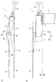
- 2A and 2B are views of the industrial robot 1 shown in FIG. 1, wherein FIG. 2A is a plan view and FIG. 2B is a side view.
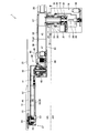
- FIG. 3 is a cross-sectional view for explaining the internal structure of the industrial robot 1 shown in FIG. 2 from the side.
- the industrial robot 1 (hereinafter referred to as “robot 1”) of this embodiment uses a glass substrate 2 (hereinafter referred to as “substrate 2”) for an organic EL (organic electroluminescence) display, which is an object to be transported. It is a robot for carrying.
- the robot 1 is a robot suitable for transporting a relatively large substrate 2. As shown in FIG. 1, the robot 1 is used by being incorporated in an organic EL display manufacturing system 3.
- the manufacturing system 3 includes a transfer chamber 4 (hereinafter referred to as “chamber 4”) disposed in the center, and a plurality of process chambers 5 to 10 (hereinafter referred to as “chambers 5 to 10” disposed so as to surround the chamber 4). ")").
- the inside of the chamber 4 and the chambers 5 to 10 are in a vacuum.
- a part of the robot 1 is disposed inside the chamber 4.
- a fork unit 21 (described later) constituting the robot 1 enters the chambers 5 to 10 enters the chambers 5 to 10, the robot 1 transports the substrate 2 between the chambers 5 to 10. That is, the robot 1 transports the substrate 2 in a vacuum.
- Various devices and the like are arranged in the chambers 5 to 10, and the substrate 2 transferred by the robot 1 is accommodated. In the chambers 5 to 10, various processes are performed on the substrate 2. A more specific configuration of the manufacturing system 3 will be described later.
- the robot 1 includes a hand 13 on which the substrate 2 is mounted, an arm 14 to which the hand 13 is pivotally connected to a distal end side thereof, and a proximal end side of the arm 14 is rotated.
- the main body part 15 connected so that it is possible and the raising / lowering mechanism 16 which raises / lowers the main body part 15 are provided.
- the main body 15 and the lifting mechanism 16 are accommodated in a substantially bottomed cylindrical case body 17.
- a flange 18 formed in a disk shape is fixed to the upper end of the case body 17.
- the flange 18 is formed with a through hole in which the upper end portion of the main body 15 is disposed.
- FIG. 2A the main body 15, the lifting mechanism 16, the case body 17, and the like are not shown.
- the hand 13 and the arm 14 are arranged on the upper side of the main body 15. Further, the hand 13 and the arm 14 are disposed on the upper side of the flange 18.
- a part of the robot 1 is disposed inside the chamber 4. Specifically, a portion of the robot 1 above the lower end surface of the flange 18 is disposed inside the chamber 4. That is, the part above the lower end surface of the flange 18 of the robot 1 is disposed in the vacuum region VR, and the hand 13 and the arm 14 are disposed in a vacuum.
- a portion of the robot 1 below the lower end surface of the flange 18 is disposed in the atmospheric region AR (in the atmosphere).
- the hand 13 includes a base 20 connected to the arm 14 and four forks 21 on which the substrate 2 is mounted.
- the fork portion 21 is formed in a straight line. Of the four fork portions 21, two fork portions 21 are arranged in parallel with a predetermined distance therebetween.
- the two fork portions 21 are fixed to the base portion 20 so as to protrude from the base portion 20 to one side in the horizontal direction.
- the remaining two fork portions 21 are fixed to the base portion 20 so as to protrude from the base portion 20 toward the opposite side of the two fork portions 21 protruding from the base portion 20 to one side in the horizontal direction.
- the arm 14 is composed of two arm parts, a first arm part 23 and a second arm part 24.
- the first arm part 23 and the second arm part 24 are formed in a hollow shape. That is, the entire arm 14 is formed in a hollow shape.
- the base end side of the first arm portion 23 is rotatably connected to the main body portion 15.
- the proximal end side of the second arm portion 24 is rotatably connected to the distal end side of the first arm portion 23. That is, the 1st arm part 23 and the 2nd arm part 24 are connected so that relative rotation is mutually possible.
- the hand 13 is rotatably connected to the distal end side of the second arm portion 24.
- the connecting portion between the arm 14 and the main body portion 15 (that is, the connecting portion between the first arm portion 23 and the main body portion 15) is a joint portion 25.
- a connecting portion between the first arm portion 23 and the second arm portion 24 is a joint portion 26.
- a connecting portion between the arm 14 and the hand 13 (that is, a connecting portion between the second arm portion 24 and the hand 13) is a joint portion 27.
- the distance between the rotation center of the second arm portion 24 relative to the first arm portion 23 and the rotation center of the first arm portion 23 relative to the main body portion 15 is the rotation center of the second arm portion 24 relative to the first arm portion 23.
- the distance from the center of rotation of the hand 13 with respect to the second arm portion 24 is equal.
- the joint part 26 is a first joint part that connects the first arm part 23 and the second arm part 24, and the joint part 27 is a second joint part that connects the second arm part 24 and the hand 13. It is.
- the first arm portion 23 is attached to the main body portion 15 so as to extend from the main body portion 15 to one side in the horizontal direction.
- a counterweight 28 is attached to the first arm portion 23 so as to extend from the main body portion 15 on the side opposite to the direction in which the first arm portion 23 extends (that is, the other side in the horizontal direction).
- the second arm part 24 is disposed above the first arm part 23. Further, the hand 13 is disposed above the second arm portion 24.
- a motor 31 for rotating the first arm portion 23 with respect to the main body portion 15 is attached to the main body portion 15.
- the main body 15 includes a hollow rotary shaft 32 to which the proximal end side of the first arm portion 23 is fixed, a speed reducer 33 that decelerates rotation of the motor 31 and transmits it to the first arm portion 23, and a speed reducer 33.
- a substantially cylindrical holding member 34 that holds the case body and rotatably holds the hollow rotary shaft 32 is provided.
- the reduction gear 33 is a hollow reduction gear in which a through hole is formed at the center in the radial direction.
- the speed reducer 33 is arranged so that the axial center of the through hole coincides with the axial center of the hollow rotary shaft 32.
- a motor 31 is connected to the input side of the speed reducer 33 via a pulley and a belt.
- the lower end of the hollow rotary shaft 32 is fixed to the output side of the speed reducer 33.
- a lower surface on the proximal end side of the first arm portion 23 is fixed to the upper end of the hollow rotary shaft 32.
- the hollow rotary shaft 32 is disposed on the inner peripheral side of the holding member 34, and a bearing is disposed between the outer peripheral surface of the hollow rotary shaft 32 and the inner peripheral surface of the holding member 34.
- a magnetic fluid seal 35 that prevents the outflow of air to the vacuum region VR is disposed at the joint portion 25.
- the magnetic fluid seal 35 is disposed between the outer peripheral surface of the hollow rotary shaft 32 and the inner peripheral surface of the holding member 34.
- a bellows 36 for preventing the outflow of air to the vacuum region VR is disposed at the joint portion 25.
- a bellows 36 is disposed on the outer peripheral side of the magnetic fluid seal 35 and on the outer peripheral side of the holding member 34.
- the lower end of the bellows 36 is fixed to the holding member 34, and the upper end of the bellows 36 is fixed to the flange 18.
- the elevating mechanism 16 includes a screw member 38 that is arranged with the vertical direction as an axial direction, a nut member 39 that engages with the screw member 38, and a motor 40 that rotates the screw member 38.
- the screw member 38 is rotatably attached to the bottom surface side of the case body 17.
- the motor 40 is attached to the bottom surface side of the case body 17.
- the screw member 38 is connected to the motor 40 via a pulley and a belt.
- the nut member 39 is attached to the main body 15 via a predetermined bracket. In this embodiment, when the motor 40 rotates, the screw member 38 rotates, and the main body 15 moves up and down together with the nut member 39.
- the lifting mechanism 16 includes a guide shaft for guiding the main body portion 15 in the vertical direction and a guide block that engages with the guide shaft and slides in the vertical direction.
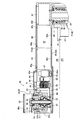
- FIG. 4 is an enlarged view of the first arm portion 23 and the joint portion 26 shown in FIG.
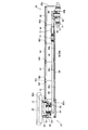
- FIG. 5 is an enlarged view of the second arm portion 24 and the joint portion 27 shown in FIG.
- the first arm portion 23 and the second arm portion 24 are formed in a hollow shape.
- a motor 46 as a first motor for rotating the second arm portion 24 with respect to the first arm portion 23
- a second arm portion A motor 47 as a second motor for rotating the hand 13 with respect to 24 is arranged.
- the joint portion 26 includes a speed reducer 48 as a first speed reducer that decelerates the rotation of the motor 46 and transmits it to the second arm portion 24.
- the speed reducer 48 is a hollow speed reducer in which a through hole is formed at the center in the radial direction.
- the joint portion 26 includes a hollow rotary shaft 50 and a hollow rotary shaft 51 disposed on the outer peripheral side of the hollow rotary shaft 50 and coaxially with the hollow rotary shaft 50.
- a bearing is disposed between the outer peripheral surface of the hollow rotary shaft 50 and the inner peripheral surface of the hollow rotary shaft 51.
- a motor 46 is connected to the input side of the speed reducer 48 via pulleys 52 and 53 and a belt 54.
- the lower end of the hollow rotary shaft 51 is fixed to the output side of the speed reducer 48.
- the speed reducer 48 is arranged so that the axial center of the through hole coincides with the axial center of the hollow rotary shaft 51.
- the upper end of the hollow rotary shaft 51 is fixed to the lower surface on the proximal end side of the second arm portion 24.
- the case body of the speed reducer 48 is fixed to a holding member 55 formed in a substantially cylindrical shape.
- the holding member 55 is fixed to the distal end side of the first arm portion 23.
- the holding member 55 is disposed on the outer peripheral side of the hollow rotary shaft 51.
- a pulley 57 is fixed to the lower end side of the hollow rotary shaft 50.
- a pulley 58 is fixed to the output shaft of the motor 47.
- a belt 59 is stretched between the pulley 57 and the pulley 58.
- a pulley 60 is fixed to the upper end of the hollow rotary shaft 50.
- the pulley 60 is disposed inside the proximal end of the second arm portion 24 formed in a hollow shape.
- the joint portion 27 includes a speed reducer 61 as a second speed reducer that decelerates the rotation of the motor 47 and transmits it to the hand 13, and a hollow rotary shaft 62.
- the speed reducer 61 is a hollow speed reducer in which a through hole is formed at the center in the radial direction.
- a pulley 63 is fixed on the input side of the speed reducer 61.
- a belt 64 is bridged between the pulley 60 and the pulley 63.
- the lower end of the hollow rotary shaft 62 is fixed to the output side of the speed reducer 61.
- the reduction gear 61 is arranged so that the axial center of the through hole coincides with the axial center of the hollow rotary shaft 62.
- the upper end of the hollow rotary shaft 62 is fixed to the lower surface of the base 20 of the hand 13.
- the case body of the speed reducer 61 is fixed to a holding member 65 formed in a substantially cylindrical shape.
- the holding member 65 is fixed to the distal end side of the second arm portion 24.
- the holding member 65 is disposed on the outer peripheral side of the hollow rotary shaft 62.
- the power of the motor 47 is transmitted to the base portion 20 of the hand 13 through the pulleys 57, 58, 60, 63, the belts 59, 64, the speed reducer 61, etc., and the hand 13 rotates.
- the internal space 45 of the first arm portion 23 is sealed, and the pressure in the internal space 45 is atmospheric pressure.
- the internal space 66 of the second arm portion 24 is also sealed, and the pressure in the internal space 66 is atmospheric pressure. That is, the internal spaces 45 and 66 of the arm 14 are at atmospheric pressure.
- the internal space 45 and the internal space 66 communicate with each other via the inner peripheral side of the hollow rotary shaft 50.
- a through hole (not shown) leading to the inner peripheral side of the hollow rotary shaft 32 is formed on the lower surface on the proximal end side of the first arm portion 23, and the internal space 45 is a main body that is at atmospheric pressure. It communicates with the inside of the part 15.
- the motors 46 and 47 are disposed in the internal space 45.
- the speed reducer 48 is disposed in the internal space 45 on the distal end side of the first arm portion 23, and the speed reducer 61 is disposed in the internal space 66 on the distal end side of the second arm portion 24. That is, the motors 46 and 47 and the speed reducers 48 and 61 are disposed in the atmosphere.
- a cooling pipe 70 for cooling the motor 46 is wound around the motor 46.
- the cooling pipe 70 can be supplied with compressed air, and the motor 46 is cooled by the compressed air passing through the inside of the cooling pipe 70. In this embodiment, since the amount of heat generated by the motor 47 is smaller than the amount of heat generated by the motor 46, no cooling pipe is wound around the motor 47.
- a magnetic fluid seal 71 for securing the sealed state of the internal space 45 is disposed at the joint portion 26, and a magnetic fluid seal 72 for securing the sealed state of the internal space 66 is disposed at the joint portion 27.
- the magnetic fluid seal 71 that prevents the air from flowing out from the internal space 45 to the vacuum region VR is disposed in the joint portion 26, and the air flow from the internal space 66 to the vacuum region VR is prevented in the joint portion 27.
- a magnetic fluid seal 72 is disposed.
- the magnetic fluid seal 71 is disposed between the outer peripheral surface of the hollow rotary shaft 51 and the inner peripheral surface of the holding member 55, and the magnetic fluid seal 72 is formed between the outer peripheral surface of the hollow rotary shaft 62 and the inner peripheral surface of the holding member 65. It is arranged between.
- a tension pulley 73 for adjusting the tension of the belt 64 is disposed in the internal space 66.
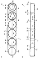
- FIG. 6A and 6B are views of the arm portion main body 80 of the second arm portion 24 shown in FIG. 5, in which FIG. 6A is a plan view and FIG. 6B is a cross-sectional view taken along the line EE of FIG.
- FIG. 7 is an enlarged view of a portion F in FIG.
- FIG. 8 is an enlarged view of a portion G in FIG.
- the second arm portion 24 includes an arm portion main body 80 and a plurality of lid members 81.
- the arm part main body 80 includes an upper surface part 80a constituting the upper surface of the arm part main body 80, and a lower surface part 80b constituting the lower surface of the arm part main body 80 and facing the upper surface part 80a in a substantially parallel manner with a predetermined gap.
- a side surface portion 80c that connects the outer peripheral end of the upper surface portion 80a and the outer peripheral end of the lower surface portion 80b.
- the upper surface portion 80a and the lower surface portion 80b are formed in an elongated, substantially oval flat plate shape, and face each other in the vertical direction.
- the side surface portion 80c is formed in a cylindrical shape having an elongated oval shape when viewed from the vertical direction.
- a space surrounded by the upper surface portion 80a, the lower surface portion 80b, and the side surface portion 80c is an internal space 66.
- the upper surface portion 80a is a first flat surface portion
- the lower surface portion 80b is a second flat surface portion.
- the base end side of the second arm portion 24 of the upper surface portion 80a and the lower surface portion 80b is referred to as “base end side”
- the distal end side of the second arm portion 24 of the upper surface portion 80a and the lower surface portion 80b is “ It shall be “tip side”.
- An insertion hole 80d through which the hollow rotary shaft 62 and the holding member 65 are inserted is formed on the tip side of the upper surface portion 80a.
- a work hole 80e for assembling the joint portion 26 is formed on the base end side of the upper surface portion 80a.
- the insertion hole 80d and the work hole 80e are formed in a round hole shape penetrating the upper surface portion 80a.
- a plurality of through holes 80f communicating with the internal space 66 are formed between the insertion hole 80d and the work hole 80e in the upper surface portion 80a.
- four through holes 80f are formed in the upper surface portion 80a at a constant pitch.
- the through hole 80f is formed in a round hole shape. That is, the through hole 80f is formed in a circular shape.
- the inner diameter of the working hole 80e is equal to the inner diameter of the through hole 80f.
- An annular groove 80g is formed on the upper surface of the upper surface portion 80a so as to be depressed downward.
- five groove portions 80g are formed. Of the five groove portions 80g, each of the four groove portions 80g is formed so as to surround each of the four through holes 80f, and the remaining one groove portion 80g is formed so as to surround the working hole 80e. Has been.
- An insertion hole 80k through which the hollow rotary shaft 50 is inserted is formed on the base end side of the lower surface portion 80b.
- a work hole 80m for assembling the joint portion 27 is formed on the distal end side of the lower surface portion 80b.
- the insertion hole 80k and the work hole 80m are formed in a round hole shape penetrating the lower surface portion 80b.
- the insertion hole 80k is formed below the work hole 80e formed in the upper surface portion 80a, and the work hole 80m is formed below the insertion hole 80d formed in the upper surface portion 80a.
- a plurality of concave portions 80n that are recessed downward are formed on the upper surface of the lower surface portion 80b (that is, the surface facing the upper surface portion 80a).
- the concave portion 80n is formed so as not to penetrate the lower surface portion 80b.
- four concave portions 80n are formed at a constant pitch.
- the recess 80n is formed in a circular shape. Specifically, the recess 80n is formed in a circular shape having the same inner diameter as the inner diameter of the through hole 80f.
- the four recesses 80n are formed at the same pitch as the pitch of the four through holes 80f.
- the recess 80n is formed so as to overlap with the through hole 80f when viewed from the vertical direction, and the inner peripheral surface of the through hole 80f and the inner peripheral surface of the recess 80n are viewed from the vertical direction. It is almost coincident.
- a mounting seat 80p for mounting the tension pulley 73 is formed in the recess 80n arranged on the most proximal side.
- the arm body 80 is made of an aluminum alloy.
- the arm portion main body 80 is formed by cutting an aluminum alloy block, and the upper surface portion 80a, the lower surface portion 80b, and the side surface portion 80c are integrated. That is, the internal space 66 is formed by cutting using a cutting tool inserted from the through hole 80f, the insertion holes 80d and 80k, and the work holes 80e and 80m, and the internal space 66 is formed by cutting.
- the upper surface portion 80a, the lower surface portion 80b, and the side surface portion 80c are also formed.
- the lid member 81 is formed in a disk shape having an outer diameter larger than the inner diameter of the through hole 80f.
- the outer diameter of the lid member 81 is larger than the outer diameter of the groove 80g formed in an annular shape.
- the lid member 81 is fixed to the upper surface of the upper surface portion 80a so as to close the through hole 80f.
- An annular seal member (not shown) that prevents the outflow of air from the internal space 66 is disposed between the upper surface portion 80 a and the lid member 81. This seal member is fitted into a groove 80g formed so as to surround the through hole 80f.
- the working hole 80e is covered with a lid member 82 formed in the same shape as the lid member 81. That is, the lid member 82 is fixed to the upper surface of the upper surface portion 80a so as to close the work hole 80e.
- An annular seal member (not shown) that prevents the outflow of air from the internal space 66 is disposed between the upper surface portion 80 a and the lid member 82. This seal member is fitted into a groove 80g formed so as to surround the work hole 80e.
- a disk-shaped lid member 83 is fixed to the lower surface of the lower surface portion 80b so as to close the work hole 80m.
- An annular seal member (not shown) that prevents the outflow of air from the internal space 66 is disposed between the lower surface portion 80 b and the lid member 83. This seal member is fitted in an annular groove formed on the outer peripheral side of the lid member 83.
- the first arm portion 23 includes an arm portion main body 85 and a plurality of lid members 86, similarly to the second arm portion 24.
- the arm body 85 includes an upper surface 85 a that constitutes the upper surface of the arm body 85, a lower surface of the arm body 85, and substantially parallel to the upper surface 85 a via a predetermined gap. It is comprised from the lower surface part 85b opposed, and the side part 85c which connects the outer peripheral end of the upper surface part 85a, and the outer peripheral end of the lower surface part 85b.
- the upper surface portion 85a and the lower surface portion 85b are formed in an elongated, substantially oval flat plate shape.
- the side surface portion 85c is formed in a cylindrical shape having an elongated oval shape when viewed from the up-down direction.
- a space surrounded by the upper surface portion 85a, the lower surface portion 85b, and the side surface portion 85c is an internal space 45.
- the upper surface portion 85a is a first flat surface portion
- the lower surface portion 85b is a second flat surface portion.
- the base end side of the first arm portion 23 of the upper surface portion 85a and the lower surface portion 85b is referred to as “base end side”
- the distal end side of the first arm portion 23 of the upper surface portion 85a and the lower surface portion 85b is “ It shall be “tip side”.
- An insertion hole 85d through which the hollow rotary shafts 50 and 51 and the holding member 55 are inserted is formed on the top end side of the upper surface portion 85a. Further, a working hole 85e for attaching the motors 46 and 47 is formed on the distal end side of the upper surface portion 85a, and a working hole 85f for assembling the joint portion 25 is formed on the proximal end side of the upper surface portion 85a. Has been.
- the insertion hole 85d and the working holes 85e and 85f are formed in a round hole shape penetrating the upper surface portion 85a.
- a plurality of through holes 85g communicating with the internal space 45 are formed between the work hole 85e and the work hole 85f in the upper surface portion 85a.
- two through holes 85g are formed in the upper surface portion 85a at a predetermined pitch.
- the through hole 85g is formed in a round hole shape. That is, the through hole 85g is formed in a circular shape.
- the inner diameters of the working holes 85e and 85f are equal to the inner diameter of the through hole 85g.
- An annular groove portion is formed on the upper surface of the upper surface portion 85a so as to be depressed downward.
- five groove portions are formed. Each of the five grooves is formed to surround each of the insertion hole 85d, the working holes 85e and 85f, and the two through holes 85g.
- a work hole 85m for assembling the joint portion 26 and attaching the motors 46 and 47 is formed on the distal end side of the lower surface portion 85b.
- the working hole 85m is formed in a round hole shape penetrating the lower surface portion 85b.
- the work hole 85m is formed below the insertion hole 85d and the work hole 85e formed in the upper surface portion 85a.
- a plurality of concave portions 85n that are recessed downward are formed on the upper surface of the lower surface portion 85b (that is, the surface facing the upper surface portion 85a).
- the recess 85n is formed so as not to penetrate the lower surface portion 85b.
- two concave portions 85n are formed at a predetermined pitch.
- the recess 85n is formed in a circular shape.
- the recess 85n is formed in a circular shape having the same inner diameter as that of the through hole 85g.
- the two recesses 85n are formed at the same pitch as the pitch of the two through holes 85g.
- the recess 85n is formed so as to overlap with the through hole 85g when viewed from the vertical direction. When viewed from the vertical direction, the inner peripheral surface of the through hole 85g and the inner peripheral surface of the recess 85n are formed. It is almost coincident.
- the arm part main body 85 is formed by cutting an aluminum alloy block similarly to the arm part main body 80, and the upper surface part 85a, the lower surface part 85b, and the side surface part 85c are integrated. That is, the internal space 45 is formed by cutting using a cutting tool inserted from the through hole 85g, the insertion hole 85d, and the working holes 85e, 85f, and 85m, and the internal space 45 is formed by cutting. Thus, the upper surface portion 85a, the lower surface portion 85b, and the side surface portion 85c are also formed.
- the lid member 86 is formed in a disk shape having an outer diameter larger than the inner diameter of the through hole 85g.
- the outer diameter of the lid member 86 is larger than the outer diameter of the annular groove formed on the upper surface of the upper surface portion 85a.
- the lid member 86 is fixed to the upper surface of the upper surface portion 85a so as to close the through hole 85g.
- An annular seal member (not shown) that prevents the outflow of air from the internal space 45 is disposed between the upper surface portion 85 a and the lid member 86.
- the seal member is fitted in a groove formed so as to surround the through hole 85g.
- a lid member 87 formed in the same shape as the lid member 86 is fixed to the upper surface of the upper surface portion 85a so as to block the working hole 85f.
- An annular seal member (not shown) that prevents the outflow of air from the internal space 45 is disposed between the upper surface portion 85 a and the lid member 87. The seal member is fitted in a groove formed so as to surround the working hole 85f.
- a lid member 88 formed in a substantially bottomed cylindrical shape is fixed to the upper surface of the upper surface portion 85a so as to block the working hole 85e.
- An annular seal member (not shown) that prevents the outflow of air from the internal space 45 is disposed between the upper surface portion 85 a and the lid member 88. This seal member is fitted into a groove formed so as to surround the working hole 85e.
- a disk-shaped lid member 89 is fixed to the lower surface of the lower surface portion 85b so as to close the working hole 85m.
- An annular seal member (not shown) that prevents the outflow of air from the internal space 45 is disposed between the lower surface portion 85 b and the lid member 89. This seal member is fitted into an annular groove formed on the outer peripheral side of the lid member 89.
- the manufacturing system 3 includes the plurality of chambers 5 to 10 arranged so as to surround the chamber 4.
- six chambers 5 to 10 are arranged so as to surround the chamber 4.
- each of three directions orthogonal to each other is defined as an X direction, a Y direction, and a Z direction.
- the robot 1 is arranged such that its vertical direction coincides with the Z direction. Therefore, in the following, the Z direction is the vertical direction.
- the X1 direction side is the “right” side
- the X2 direction side is the “left” side
- the Y1 direction side is the “front” side
- the Y2 direction side is the “rear (rear)” side.
- the chamber 4 is formed so that the shape when viewed from above and below is a substantially octagonal shape.
- the chamber 5 is arranged so as to be connected to the left end of the chamber 4, and the chamber 6 is arranged so as to be connected to the right end of the chamber 4.
- the chamber 7 and the chamber 8 are arranged so as to be connected to the rear end of the chamber 4.
- the chamber 7 and the chamber 8 are adjacent in the left-right direction.
- the chamber 7 is disposed on the left side
- the chamber 8 is disposed on the right side.
- the chamber 9 and the chamber 10 are arranged so as to be connected to the front end of the chamber 4.
- the chamber 9 and the chamber 10 are adjacent in the left-right direction.
- the chamber 9 is disposed on the left side
- the chamber 10 is disposed on the right side.
- a virtual line parallel to the left and right direction passing through the rotation center C1 of the first arm portion 23 with respect to the main body 15 indicates the center position of the chambers 5 and 6 in the front and rear direction. It is arranged to pass.
- the chambers 7 and 8 are arranged so that a virtual line parallel to the front-rear direction passing through the rotation center C ⁇ b> 1 passes through the center position in the left-right direction between the chambers 7 and 8. That is, the center positions of the chambers 7 and 8 in the left-right direction are offset with respect to the rotation center C1.
- the chambers 9 and 10 are arranged such that a virtual line passing through the rotation center C1 and parallel to the front-rear direction passes through the center position in the left-right direction between the chambers 9 and 10. That is, the center positions of the chambers 9 and 10 in the left-right direction are offset with respect to the rotation center C1. Further, in the left-right direction, the chamber 7 and the chamber 9 are disposed at the same position, and the chamber 8 and the chamber 10 are disposed at the same position.
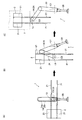
- FIG. 9 is a view for explaining the movement of the industrial robot 1 when unloading the substrate 2 from the process chamber 5 shown in FIG. 1 and loading the substrate 2 into the process chamber 6.
- FIG. 10 is a view for explaining the movement of the industrial robot 1 when the substrate 2 is carried into the process chamber 7 shown in FIG.
- the robot 1 drives the motors 31, 40, 46, 47 to transfer the substrate 2 between the chambers 5 to 10.
- the robot 1 unloads the substrate 2 from the chamber 5 and loads the substrate 2 into the chamber 6. That is, the robot 1 extends the arm 14 and mounts the substrate 2 in the chamber 5 as shown in FIG. 9 (A), and then, as shown in FIG. The arm 14 is contracted until the arm portion 24 overlaps with the vertical direction, and the substrate 2 is unloaded from the chamber 5. Thereafter, the robot 1 rotates the hand 13 by 180 °, extends the arm 14, and loads the substrate 2 into the chamber 6 as shown in FIG. 9C.
- the robot 1 carries the substrate 2 carried out of the chamber 5 into the chamber 7 (see FIG. 10).
- the robot 1 first drives the motors 31, 46, 47 from the state in which the arm 14 is contracted as shown in FIG. 10A, and the fork section as shown in FIG. 10B.
- the rotation center C2 of the hand 13 with respect to the second arm portion 24 in the left-right direction and the chamber 7 in the left-right direction so that 21 is parallel to the front-rear direction and the substrate 2 is disposed on the rear end side of the hand 13
- the hand 13, the first arm part 23, and the second arm part 24 are rotated so that their centers substantially coincide with each other.
- the robot 1 extends the arm 14 and carries the substrate 2 into the chamber 7 as shown in FIG.
- the robot 1 carries, for example, the substrate 2 carried out from the chamber 5 into the chamber 9.
- the robot 1 first drives the motors 31, 46, 47 from the state in which the arm 14 is contracted, the fork portion 21 is parallel to the front-rear direction, and the substrate 2 is disposed on the front end side of the hand 13.
- the hand 13, the first arm portion 23, and the second arm portion 24 are rotated so that the rotation center C2 and the center of the chamber 9 in the left-right direction substantially coincide with each other.
- the robot 1 extends the arm 14 and carries the substrate 2 into the chamber 9.
- the robot 1 loads the substrate 2 unloaded from the chamber 5 into the chamber 8.
- the robot 1 first drives the motors 31, 46, 47 from the contracted state of the arm 14, the fork portion 21 becomes parallel to the front-rear direction, and the substrate 2 is arranged on the rear end side of the hand 13.
- the hand 13, the first arm portion 23, and the second arm portion 24 are rotated so that the rotation center C2 and the center of the chamber 8 in the left-right direction substantially coincide with each other in the left-right direction.
- the robot 1 extends the arm 14 and carries the substrate 2 into the chamber 8.
- the robot 1 carries the substrate 2 unloaded from the chamber 5 into the chamber 10.
- the robot 1 first drives the motors 31, 46, 47 from the state in which the arm 14 is contracted, the fork portion 21 is parallel to the front-rear direction, and the substrate 2 is disposed on the front end side of the hand 13.
- the hand 13, the first arm portion 23, and the second arm portion 24 are rotated so that the rotation center C2 substantially coincides with the center of the chamber 10 in the left-right direction in the left-right direction.
- the robot 1 extends the arm 14 and carries the substrate 2 into the chamber 10.
- the hand 13 and the first arm part 23 have the same turning angle of the first arm part 23 with respect to the main body part 15 and the turning angle of the hand 13 with respect to the second arm part 24, and
- the rotation direction of the first arm portion 23 with respect to the main body portion 15 and the rotation direction of the hand 13 with respect to the second arm portion 24 are reversed. That is, the motors 31 and 47 have the same rotation angle of the first arm portion 23 with respect to the main body portion 15 and the rotation angle of the hand 13 with respect to the second arm portion 24, and the first arm portion 23 with respect to the main body portion 15.
- the rotation direction and the rotation direction of the hand 13 with respect to the second arm portion 24 rotate in the opposite direction. Therefore, the direction of the hand 13 is kept constant when the substrate 2 is unloaded and loaded.
- a plurality of through holes 80f are formed in the arm main body 80, and the lid member 81 that closes the through holes 80f and the upper surface of the arm main body 80.
- a plurality of through holes 85g are formed in the arm main body 85, and atmospheric pressure is generated between the lid member 86 that closes the through holes 85g and the upper surface 85a of the arm main body 85.
- An annular seal member that prevents the outflow of air from the internal space 45 is disposed. Therefore, in this embodiment, even if the robot 1 is enlarged and the first arm portion 23 is enlarged, it is possible to reduce the size of each of the plurality of seal members. The seal member can be easily handled during assembly. Therefore, in this embodiment, even if the robot 1 is increased in size, it is possible to reduce work errors when attaching a seal member for ensuring the airtightness of the internal spaces 45 and 66 of the arm 14.
- the second arm portion 24 since the internal space 66 of the second arm portion 24 arranged in a vacuum is at atmospheric pressure, the second arm portion 24 formed in a hollow shape.
- a concave portion 80n is formed on the upper surface of the lower surface portion 80b of the arm portion main body 80 so as to overlap with the through hole 80f when viewed in the vertical direction. Therefore, the second arm portion 24 can be deformed so that the second arm portion 24 swells substantially uniformly toward the upper and lower sides.
- the strength of the upper surface portion 80a in which the plurality of through holes 80f are formed is lower than the strength of the lower surface portion 80b.
- the concave portion 80n is formed on the upper surface of the lower surface portion 80b, and the strength of the lower surface portion 80b is increased by the upper pressure of the upper surface portion 80a. Therefore, the second arm portion 24 can be deformed so that the second arm portion 24 swells substantially uniformly toward the upper and lower sides. Therefore, in this embodiment, even if the plurality of through holes 80f are formed in the upper surface portion 80a, the second arm portion 24 is deformed or twisted so as to be inclined to one side in the vertical direction. Can be prevented from being deformed.
- the first arm portion 23 formed in a hollow shape is used.
- a concave portion 85n is formed on the upper surface of the lower surface portion 85b of the arm portion main body 85 so as to overlap with the through hole 85g when viewed in the vertical direction. Therefore, the first arm portion 23 can be deformed so that the first arm portion 23 swells substantially uniformly toward the upper and lower sides. Therefore, in this embodiment, even if a plurality of through holes 85g are formed in the upper surface portion 85a, the first arm portion 23 is deformed or twisted so as to be inclined to one side in the vertical direction. Can be prevented from being deformed.
- the arm 14 is deformed so as to be inclined to one side in the vertical direction. It is possible to prevent the arm 14 from being deformed so as to be twisted, and it is possible to ensure the positional accuracy of the arm 14 on the tip side. Therefore, in this embodiment, even if the plurality of through holes 80f and 85g are formed in the upper surface portions 80a and 85a, the substrate 2 can be accurately transferred to a predetermined position in the chambers 5 to 10. That is, in this embodiment, it is possible to suppress the deviation of the substrate 2 from the target arrival position and increase the conveyance accuracy of the substrate 2.
- the inner peripheral surface of the through hole 80f and the inner peripheral surface of the recess 80n substantially coincide with each other when viewed in the vertical direction, and the inner peripheral surface of the through hole 85g.
- the inner peripheral surface of the recess 85n substantially coincide with each other, and therefore, the first arm portion 23 and the second arm portion 24 so that the first arm portion 23 and the second arm portion 24 swell substantially uniformly toward the upper and lower sides. It becomes easy to deform. Therefore, in this embodiment, even when the plurality of through holes 80f and 85g are formed in the upper surface portions 80a and 85a, the arm 14 is deformed so as to be inclined to one side in the vertical direction, and the arm 14 is deformed so as to be twisted. It is possible to effectively suppress such a situation, and as a result, it is possible to increase the positional accuracy of the tip side of the arm 14.
- the arm main bodies 80 and 85 are formed by cutting an aluminum alloy block. Therefore, in the present embodiment, the arm main bodies 80 and 85 are formed by joining the upper surface portions 80a and 85a and the lower surface portions 80b and 85b and the side surface portions 80c and 85c formed separately from each other. In comparison, it becomes easier to prevent the outflow of air from the internal spaces 45 and 66. Further, in this embodiment, the amount of gas (outgas) released from the arm main bodies 80 and 85 into the vacuum can be reduced as compared with the case where the arm main bodies 80 and 85 are formed by casting. It becomes possible.
- the entire arm 14 is formed in a hollow shape, and the internal spaces 45 and 66 of the arm 14 are at atmospheric pressure. Therefore, in this embodiment, even if the temperature of the substrate 2 mounted on the hand 13 and transported in vacuum is high, the entire arm 14 is cooled from the inside of the arm 14 to suppress the temperature rise of the entire arm 14. It becomes possible. Therefore, in this embodiment, even if the temperature of the substrate 2 mounted and transported on the hand 13 is high, the thermal expansion of the entire arm 14 can be suppressed, and as a result, the predetermined positions of the chambers 5 to 10 can be reduced. It becomes possible to convey the board
- the entire arm 14 is formed in a hollow shape, and the internal spaces 45 and 66 of the arm 14 are at atmospheric pressure. Even if the temperature of the substrate 2 is high, it is possible to suppress the temperature rise of all the bearings arranged inside the arm 14 and to suppress the decrease in the service life thereof. That is, in this embodiment, even if the temperature of the substrate 2 mounted on the hand 13 and transported is high, the life of all the bearings constituting the motors 46 and 47, the speed reducers 48 and 61, the tension pulley 73 and the like is reduced. It becomes possible to suppress.
- the internal spaces 45 and 66 of the arm 14 are at atmospheric pressure, in the vacuum region VR, the motors 46 and 47, the speed reducers 48 and 61, the pulley 52, Generation of gas (outgas) from 53, 57, 58, 60, 63 and belts 54, 59, 64 can be prevented.
- the internal spaces 45 and 66 of the arm 14 are at atmospheric pressure, and the surface area of the arm 14 disposed in the vacuum region VR can be reduced. The amount of outgas generated from 14 can be reduced. Therefore, in this embodiment, it is possible to suppress the occurrence of a failure due to outgas in the manufacturing process of the substrate 2.
- a part of the joint part 26 is constituted by the speed reducer 48, and a part of the joint part 27 is constituted by the speed reducer 61. For this reason, in this embodiment, the rigidity of the joint portions 26 and 27 can be increased.
- the motor 47 is disposed inside the first arm portion 23. Therefore, in this embodiment, it is possible to reduce the size of the second arm portion 24 as compared with the case where the motor 47 is disposed inside the second arm portion 24.
- the motor 47 is disposed inside the first arm portion 23
- the power transmission path from the motor 47 to the hand 13 becomes long.
- the hand 13 is directly fixed to the output side of the speed reducer 61. Therefore, in this embodiment, for example, the reduction of the hand 13 is stopped as compared with the case where the reduction gear 61 is arranged to form the joint portion 26 and the reduction gear 61 and the hand 13 are connected via a belt and a pulley.
- the accuracy can be increased, and as a result, the conveyance accuracy of the substrate 2 can be increased. That is, when the speed reducer 61 is arranged so as to constitute the joint portion 26 and the speed reducer 61 and the hand 13 are connected via a belt and a pulley, the speed reducer 61 and the hand 13 are connected. Since the load after deceleration is applied to the belt, when the hand 13 stops, the belt is stretched and the stop accuracy of the hand 13 is likely to be lowered. However, in this embodiment, the load before deceleration is applied to the belt 64. It is possible to suppress the extension of the belt 64 when the hand 13 stops and to increase the stopping accuracy of the hand 13.
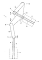
- FIG. 11 is a plan view of an industrial robot 1 according to another embodiment of the present invention (second invention).
- the arm 14 is composed of one first arm portion 23 and one second arm portion 24.
- the arm 14 may be composed of one first arm portion 23 and two second arm portions 24.
- the 1st arm part 23 is formed in the substantially V shape or linear form, and the center part becomes a base end part connected with the main-body part 15 so that rotation is possible.
- the second arm portion 24 is rotatably connected to each of the two distal ends of the first arm portion 23, and the two distal ends of the first arm portion 23 are connected to each other.
- a joint portion 26 is formed in each.
- a part of the joint part 26 is configured by the speed reducer 48 and a part of the joint part 27 is configured by the speed reducer 61 as in the above-described embodiment.
- motors 46 and 47 and a speed reducer 48 are disposed in the internal space 45 of the first arm portion 23 on each of the two distal end sides of the first arm portion 23, and the distal end sides of the two second arm portions 24.
- a reduction gear 61 is disposed in the internal space 66 of the second arm portion 24.
- the internal spaces 45 and 66 are at atmospheric pressure.
- only two fork portions 21 protruding to one side in the horizontal direction are attached to the base portion 20 of the hand 13.
- symbol is attached
- FIG. 12 is a plan view of an industrial robot 1 according to another embodiment of the present invention (second invention).
- the robot 1 includes one arm 14.
- the robot 1 may include two arms 14 whose base ends are rotatably connected to the main body portion 15.
- a part of the joint part 26 is configured by the speed reducer 48 and a part of the joint part 27 is configured by the speed reducer 61 as in the above-described embodiment.
- motors 46 and 47 and a speed reducer 48 are disposed in the internal space 45 of the first arm portion 23 on the distal end side of the first arm portion 23, and the second arm portion is disposed on each distal end side of the second arm portion 24.
- a reduction gear 61 is disposed in the internal space 66 of 24. The internal spaces 45 and 66 are at atmospheric pressure.
- the arm 14 is composed of one first arm portion 23 and one second arm portion 24.
- the arm 14 may be composed of one first arm portion 23 and two second arm portions 24.
- the 1st arm part 23 is formed in the substantially V shape or linear form, and the center part becomes a base end part connected with the main-body part 15 so that rotation is possible.
- the second arm portion 24 is rotatably connected to each of the two distal ends of the first arm portion 23, and the two distal ends of the first arm portion 23 are connected to each other.
- a joint portion 26 is formed in each.
- the robot 1 includes one arm 14.
- the robot 1 includes two robots whose base end side is rotatably connected to the main body 15.
- the arm 14 may be provided. In this case, for example, only two fork portions 21 protruding to one side in the horizontal direction are attached to the base portion 20 of the hand 13.
- the same reference numerals are given to the same configuration as the configuration of the above-described configuration or the configuration corresponding to the configuration of the above-described configuration.
- the recess 80n is formed so as to overlap with the through hole 80f when viewed from the top and bottom direction, and when viewed from the top and bottom direction, the inner peripheral surface of the through hole 80f and the inner periphery of the recess 80n. The surface is almost coincident.
- the recess 80n is formed so that a part of the recess 80n overlaps with the through hole 80f when viewed from the top and bottom, and the inner surface of the through hole 80f when viewed from the top and bottom.
- the inner peripheral surface of the recess 80n may be displaced.
- the recess 85n is formed so as to overlap with the through hole 85g when viewed from the vertical direction, and the inner peripheral surface of the through hole 85g and the recess 85n when viewed from the vertical direction.
- the recess 85n is formed so that a part of the recess 85n overlaps the through hole 85g when viewed from the top and bottom, and the recess 85n penetrates when viewed from the top and bottom.
- the inner peripheral surface of the hole 85g and the inner peripheral surface of the recess 85n may be shifted.
- the inner diameter of the recess 80n is equal to the inner diameter of the through hole 80f.
- the inner diameter of the recess 80n may be larger than the inner diameter of the through hole 80f, or may be smaller than the inner diameter of the through hole 80f.
- the inner diameter of the recess 85n is equal to the inner diameter of the through hole 85g, but the inner diameter of the recess 85n may be larger than the inner diameter of the through hole 85g or smaller than the inner diameter of the through hole 85g.
- the through-holes 80f and 85g are formed in circular shape, the through-holes 80f and 85g may be formed in polygonal shape, and are formed in elliptical shape or oval shape. Also good. Further, in the above-described form, the recesses 80n and 85n are formed in a circular shape, but the recesses 80n and 85n may be formed in a polygonal shape, or may be formed in an elliptical shape or an oval shape. .
- the recesses 80n and 85n are formed so as not to penetrate the lower surface portions 80b and 85b.
- the recesses 80n and 85n may be formed so as to penetrate the lower surface portions 80b and 85b.
- a lid member that closes the recesses 80n and 85n is fixed to the lower surfaces of the lower surface portions 80b and 85b.
- a seal member for preventing the outflow of air from the internal spaces 45 and 66 is disposed between the lid member and the lower surface portions 80b and 85b.
- the internal space 45 of the first arm portion 23 and the internal space 66 of the second arm portion 24 are at atmospheric pressure.
- the internal space 45 or the internal space 66 may be in a vacuum.
- the arm 14 is constituted by two arm parts, ie, the first arm part 23 and the second arm part 24, but the arm 14 may be constituted by one arm part. It may be good and may be constituted by three or more arm parts.
- the internal space of all the arm portions may be atmospheric pressure, or there may be an arm portion in which the internal space is vacuum. .
- the robot 1 includes a motor 46 for rotating the second arm unit 24 with respect to the first arm unit 23 and a motor 47 for rotating the hand 13 with respect to the second arm unit 24. And.
- a motor is used so that the second arm portion 24 rotates with respect to the first arm portion 23 and the hand 13 rotates with respect to the second arm portion 24 by one motor.
- a mechanism for transmitting power from the arm 14 to the arm 14 may be configured.
- the speed reducer 48 is disposed in the internal space 45 on the distal end side of the first arm portion 23.
- the speed reducer 48 may be disposed in the internal space 66 on the proximal end side of the second arm portion 24.
- the motor 47 is disposed in the internal space 45 of the first arm portion 23, but the motor 47 may be disposed in the internal space 66 of the second arm portion 24.
- the motor 46 is disposed in the internal space 45 of the first arm portion 23, but the motor 46 may be disposed in the internal space 66 of the second arm portion 24.
- the speed reducer 61 is disposed in the internal space 66 of the second arm portion 24, but the speed reducer 61 may be disposed in the internal space 45 of the first arm portion 23. In this case, at the joint portion 26, the speed reducer 48 and the speed reducer 61 are arranged so as to overlap in the axial direction.
- the robot 1 includes a motor 46 for rotating the second arm unit 24 with respect to the first arm unit 23 and a motor 47 for rotating the hand 13 with respect to the second arm unit 24. And.
- a motor is used so that the second arm portion 24 rotates with respect to the first arm portion 23 and the hand 13 rotates with respect to the second arm portion 24 by one motor.
- a mechanism for transmitting power from the arm 14 to the arm 14 may be configured.
- the arm 14 is composed of two arm parts, the first arm part 23 and the second arm part 24.
- the arm 14 may be constituted by three or more arm portions.
- each of the three or more arm portions is formed in a hollow shape, and the internal space of each of the three or more arm portions is at atmospheric pressure.
- an air-cooled or water-cooled cooling mechanism may be disposed in the internal spaces 45 and 66.
- a cooling pipe having an outlet for cooling compressed air may be arranged in the internal spaces 45 and 66.
- the cooling pipe is arranged so that the compressed air is supplied to the arrangement places of the bearings such as the speed reducers 48 and 61 and the magnetic fluid seals 71 and 72.
- the cooling pipes disposed in the internal spaces 45 and 66 are connected to a compressed air supply source disposed in the atmosphere inside the case body 17 or outside the case body 17. .
- the cooling pipe and the compressed air supply source are connected by a through hole formed in the lower surface of the proximal end side of the first arm portion 23 and a pipe routed around the inner peripheral side of the hollow rotary shaft 32.
- an electromagnetic valve is arranged inside the case body 17, and by turning on and off the electromagnetic valve, compressed air is supplied from the jet outlet of the cooling pipe, or the cooling pipe The amount of compressed air supplied from the jet outlet is adjusted.
- detection means such as a temperature sensor for detecting the temperature of the internal spaces 45 and 66 is disposed at an appropriate position in the internal spaces 45 and 66, and based on the detection result of the detection means.
- the solenoid valve is turned on and off.
- the compressed air supplied to the internal spaces 45 and 66 circulates through the entire internal spaces 45 and 66 and then is discharged to the main body 15 side. In this case, it is possible to effectively cool the entire arm 14 from the inside of the arm 14 and effectively suppress the temperature rise of the entire arm 14.
- the object to be transported by the robot 1 is the organic EL display substrate 2, but the object to be transported by the robot 1 may be a glass substrate for a liquid crystal display. It may be a semiconductor wafer or the like.
- the robot 1 is a robot for conveying a conveyance target object, the robot 1 may be a robot used for other uses, such as a welding robot.
Landscapes
- Engineering & Computer Science (AREA)
- Robotics (AREA)
- Mechanical Engineering (AREA)
- Manipulator (AREA)
- Container, Conveyance, Adherence, Positioning, Of Wafer (AREA)
Abstract
Description
図1は、本発明の実施の形態にかかる産業用ロボット1が有機ELディスプレイの製造システム3に組み込まれた状態を示す平面図である。図2は、図1に示す産業用ロボット1の図であり、(A)は平面図、(B)は側面図である。図3は、図2に示す産業用ロボット1の内部構造を側面から説明するための断面図である。
図4は、図3に示す第1アーム部23および関節部26の拡大図である。図5は、図3に示す第2アーム部24および関節部27の拡大図である。
図6は、図5に示す第2アーム部24のアーム部本体80の図であり、(A)は平面図、(B)は(A)のE-E断面の断面図である。図7は、図6(A)のF部の拡大図である。図8は、図6(B)のG部の拡大図である。
上述のように、製造システム3は、チャンバー4を囲むように配置される複数のチャンバー5~10を備えている。本形態の製造システム3では、チャンバー4を囲むように6個のチャンバー5~10が配置されている。以下では、図1において、互いに直交する3つの方向のそれぞれをX方向、Y方向およびZ方向とする。ロボット1は、その上下方向がZ方向と一致するように配置されている。したがって、以下では、Z方向を上下方向とする。また、以下では、X1方向側を「右」側、X2方向側を「左」側、Y1方向側を「前」側、Y2方向側を「後(後ろ)」側とする。
図9は、図1に示すプロセスチャンバー5から基板2を搬出してプロセスチャンバー6へ基板2を搬入する際の産業用ロボット1の動きを説明するための図である。図10は、図1に示すプロセスチャンバー7へ基板2を搬入する際の産業用ロボット1の動きを説明するための図である。
以上説明したように、(第1の発明にかかる)本形態では、アーム部本体80に複数の貫通孔80fが形成されており、貫通孔80fを塞ぐ蓋部材81とアーム部本体80の上面部80aとの間に、大気圧となっている内部空間66からの空気の流出を防止する環状のシール部材が配置されている。そのため、本形態では、ロボット1が大型化して第2アーム部24が大型化しても、複数のシール部材のそれぞれの大きさを小さくすることが可能になり、その結果、第2アーム部24を組み立てる際にシール部材を容易に取り扱うことが可能になる。同様に、本形態では、アーム部本体85に複数の貫通孔85gが形成されており、貫通孔85gを塞ぐ蓋部材86とアーム部本体85の上面部85aとの間に、大気圧となっている内部空間45からの空気の流出を防止する環状のシール部材が配置されている。そのため、本形態では、ロボット1が大型化して第1アーム部23が大型化しても、複数のシール部材のそれぞれの大きさを小さくすることが可能になり、その結果、第1アーム部23を組み立てる際にシール部材を容易に取り扱うことが可能になる。したがって、本形態では、ロボット1が大型化しても、アーム14の内部空間45、66の気密性を確保するためのシール部材を取り付ける際の作業ミスを低減することが可能になる。
図11は、本発明(第2の発明)の他の実施の形態にかかる産業用ロボット1の平面図である。
図12は、本発明(第2の発明)の他の実施の形態にかかる産業用ロボット1の平面図である。
上述した形態は、本発明の好適な形態の一例ではあるが、これに限定されるものではなく本発明の要旨を変更しない範囲において種々変形実施が可能である。
13 ハンド
14 アーム
15 本体部
23 第1アーム部(アーム部)
24 第2アーム部(アーム部)
26 関節部(第1関節部)
27 関節部(第2関節部)
45、66 内部空間
46 モータ(第1モータ)
47 モータ(第2モータ)
48 減速機(第1減速機)
80a、85a 上面部(第1平面部)
80b、85b 下面部(第2平面部)
80c、85c 側面部
80f、85g 貫通孔
80n、85n 凹部
81、86 蓋部材
Claims (10)
- 平板状の第1平面部と、前記第1平面部と所定の隙間を介して略平行に対向配置される平板状の第2平面部と、前記第1平面部の外周端と前記第2平面部の外周端とを繋ぐ側面部とを有するアームを備え、
前記アームの少なくとも一部は、前記第1平面部と前記第2平面部と前記側面部とに囲まれる内部空間を有する中空状に形成されるとともに、前記アームは、真空中に配置され、
前記内部空間は、大気圧となっており、
前記第1平面部には、前記内部空間に通じる複数の貫通孔が形成され、
前記アームは、前記第1平面部に固定され前記貫通孔を塞ぐ複数の蓋部材と、前記第1平面部と前記蓋部材との間に配置され前記内部空間からの空気の流出を防止する複数のシール部材とを備え、
前記第2平面部の、前記第1平面部との対向面には、前記第1平面部と前記第2平面部との対向方向から見たときに前記貫通孔と少なくとも一部が重なる複数の凹部が窪むように形成されていることを特徴とする産業用ロボット。 - 前記対向方向から見たときに、前記貫通孔の内周面と前記凹部の内周面とが略一致していることを特徴とする請求項1記載の産業用ロボット。
- 前記貫通孔は、円形状に形成され、
前記凹部は、前記貫通孔の内径と内径の等しい円形状に形成されていることを特徴とする請求項1または2記載の産業用ロボット。 - 前記内部空間は、前記貫通孔から挿入される切削用工具を用いた切削加工によって形成され、
前記第1平面部と前記第2平面部と前記側面部とが一体となっていることを特徴とする請求項1から3のいずれかに記載の産業用ロボット。 - 本体部と、前記本体部にその基端側が回動可能に連結されるアームと、前記アームの先端側に回動可能に連結されるハンドとを備え、
前記ハンドと前記アームとは、真空中に配置され、
前記アームの全体は、中空状に形成され、
前記アームの内部空間は、大気圧となっていることを特徴とする産業用ロボット。 - 前記アームは、互いに相対回動可能に連結される複数のアーム部によって構成され、
複数の前記アーム部のそれぞれは、中空状に形成されていることを特徴とする請求項5記載の産業用ロボット。 - 前記アームは、前記本体部にその基端側が回動可能に連結される前記アーム部としての第1アーム部と、前記第1アーム部の先端側にその基端側が回動可能に連結されるとともにその先端側に前記ハンドが回動可能に連結される前記アーム部としての第2アーム部とから構成されていることを特徴とする請求項6記載の産業用ロボット。
- 前記第1アーム部に対して前記第2アーム部を回動させるための第1モータと、前記第2アーム部に対して前記ハンドを回動させるための第2モータと、前記第1モータの回転を減速して前記第2アーム部に伝達する第1減速機と、前記第2モータの回転を減速して前記ハンドに伝達する第2減速機とを備え、
前記第1減速機は、前記第1アーム部と前記第2アーム部とを繋ぐ第1関節部の少なくとも一部を構成するとともに前記第1アーム部の内部に配置され、
前記第2減速機は、前記第2アーム部と前記ハンドとを繋ぐ第2関節部の少なくとも一部を構成するとともに前記第2アーム部の内部に配置されていることを特徴とする請求項7記載の産業用ロボット。 - 前記第1モータおよび前記第2モータは、前記第1アーム部の内部に配置されていることを特徴とする請求項8記載の産業用ロボット。
- 前記内部空間に配置される冷却機構を備えることを特徴とする請求項5から9のいずれかに記載の産業用ロボット。
Priority Applications (6)
| Application Number | Priority Date | Filing Date | Title |
|---|---|---|---|
| KR1020147027371A KR20140133894A (ko) | 2013-01-07 | 2013-10-15 | 산업용 로봇 |
| CN201380022507.0A CN104271321B (zh) | 2013-01-07 | 2013-10-15 | 工业用机器人 |
| KR1020167008103A KR101642678B1 (ko) | 2013-01-07 | 2013-10-15 | 산업용 로봇 |
| KR1020167033734A KR101878585B1 (ko) | 2013-01-07 | 2013-10-15 | 산업용 로봇 |
| TW102139981A TWI531452B (zh) | 2013-01-07 | 2013-11-04 | Industrial robots |
| TW104135495A TWI583516B (zh) | 2013-01-07 | 2013-11-04 | Industrial robots |
Applications Claiming Priority (6)
| Application Number | Priority Date | Filing Date | Title |
|---|---|---|---|
| US201361749547P | 2013-01-07 | 2013-01-07 | |
| US61/749,547 | 2013-01-07 | ||
| JP2013000541A JP6007111B2 (ja) | 2013-01-07 | 2013-01-07 | 産業用ロボット |
| JP2013-000542 | 2013-01-07 | ||
| JP2013-000541 | 2013-01-07 | ||
| JP2013000542 | 2013-01-07 |
Publications (1)
| Publication Number | Publication Date |
|---|---|
| WO2014106914A1 true WO2014106914A1 (ja) | 2014-07-10 |
Family
ID=51062236
Family Applications (1)
| Application Number | Title | Priority Date | Filing Date |
|---|---|---|---|
| PCT/JP2013/077920 Ceased WO2014106914A1 (ja) | 2013-01-07 | 2013-10-15 | 産業用ロボット |
Country Status (4)
| Country | Link |
|---|---|
| KR (3) | KR101878585B1 (ja) |
| CN (2) | CN104271321B (ja) |
| TW (2) | TWI531452B (ja) |
| WO (1) | WO2014106914A1 (ja) |
Cited By (1)
| Publication number | Priority date | Publication date | Assignee | Title |
|---|---|---|---|---|
| CN107717955A (zh) * | 2017-09-29 | 2018-02-23 | 中国科学院空间应用工程与技术中心 | 一种四自由度巡检机械臂及其控制系统、控制方法 |
Families Citing this family (6)
| Publication number | Priority date | Publication date | Assignee | Title |
|---|---|---|---|---|
| JP6918698B2 (ja) * | 2016-07-28 | 2021-08-11 | 日本電産サンキョー株式会社 | 産業用ロボット |
| JP2020069577A (ja) * | 2018-10-31 | 2020-05-07 | 日本電産サンキョー株式会社 | 産業用ロボット |
| JP7195111B2 (ja) * | 2018-10-31 | 2022-12-23 | 日本電産サンキョー株式会社 | 産業用ロボット |
| CN111361977A (zh) * | 2018-12-26 | 2020-07-03 | 沈阳新松机器人自动化股份有限公司 | 一种scara型搬运机械手 |
| JP2021019071A (ja) * | 2019-07-19 | 2021-02-15 | 日本電産サンキョー株式会社 | 産業用ロボットおよび産業用ロボットの制御方法 |
| JP2023054397A (ja) * | 2021-10-04 | 2023-04-14 | 日本電産サンキョー株式会社 | 産業用ロボット |
Citations (7)
| Publication number | Priority date | Publication date | Assignee | Title |
|---|---|---|---|---|
| JPH01216786A (ja) * | 1988-02-24 | 1989-08-30 | Toshiba Corp | 水平多関節形ロボット |
| JPH0585584U (ja) * | 1992-04-21 | 1993-11-19 | 新明和工業株式会社 | 真空チャンバ用ロボット装置 |
| JPH09150388A (ja) * | 1995-07-10 | 1997-06-10 | Smart Machines Inc | ダイレクト駆動ロボット |
| JP2009172733A (ja) * | 2008-01-25 | 2009-08-06 | Yaskawa Electric Corp | 水平多関節ロボット |
| JP2010149166A (ja) * | 2008-12-26 | 2010-07-08 | Ulvac Japan Ltd | 真空搬送装置の製造方法及び真空搬送装置 |
| JP2011011318A (ja) * | 2009-07-06 | 2011-01-20 | Seiko Epson Corp | 位置制御方法、ロボット |
| JP2011101912A (ja) * | 2009-11-10 | 2011-05-26 | Yaskawa Electric Corp | アーム機構およびそれを備えた真空ロボット |
Family Cites Families (15)
| Publication number | Priority date | Publication date | Assignee | Title |
|---|---|---|---|---|
| JPH05318350A (ja) * | 1992-05-18 | 1993-12-03 | Ebara Corp | 真空用ロボットの昇降機構 |
| JPH08309681A (ja) * | 1995-05-17 | 1996-11-26 | Ulvac Japan Ltd | 多関節型基板搬送ロボット |
| JP3030392B2 (ja) * | 1995-10-02 | 2000-04-10 | ゼテック株式会社 | 腐食性雰囲気用ロボット |
| US6126381A (en) * | 1997-04-01 | 2000-10-03 | Kensington Laboratories, Inc. | Unitary specimen prealigner and continuously rotatable four link robot arm mechanism |
| US6634851B1 (en) * | 1999-01-15 | 2003-10-21 | Asyst Technologies, Inc. | Workpiece handling robot |
| JP2002307365A (ja) * | 2001-04-11 | 2002-10-23 | Aitec:Kk | スカラロボットのアーム |
| TWI400767B (zh) * | 2004-12-10 | 2013-07-01 | 愛發科股份有限公司 | 搬運機械手臂及搬運裝置 |
| US8136422B2 (en) * | 2005-04-11 | 2012-03-20 | Nidec Sankyo Corporation | Articulated robot |
| JP4731267B2 (ja) * | 2005-09-29 | 2011-07-20 | 日本電産サンキョー株式会社 | ロボットのハンドおよびこれを用いたワーク搬送ロボット |
| JP4660350B2 (ja) * | 2005-10-27 | 2011-03-30 | 東芝機械株式会社 | 産業用ロボットのアーム機構 |
| JP4605560B2 (ja) * | 2005-12-05 | 2011-01-05 | 日本電産サンキョー株式会社 | 産業用ロボット |
| JP4617278B2 (ja) * | 2006-06-29 | 2011-01-19 | 日本電産サンキョー株式会社 | 産業用ロボット |
| JP4980127B2 (ja) * | 2007-04-24 | 2012-07-18 | 川崎重工業株式会社 | 基板搬送ロボット |
| JP5462064B2 (ja) * | 2010-04-28 | 2014-04-02 | 日本電産サンキョー株式会社 | 産業用ロボット |
| JP5798118B2 (ja) * | 2010-07-14 | 2015-10-21 | 日本電産サンキョー株式会社 | 産業用ロボット、産業用ロボットの制御方法および産業用ロボットの教示方法 |
-
2013
- 2013-10-15 KR KR1020167033734A patent/KR101878585B1/ko active Active
- 2013-10-15 CN CN201380022507.0A patent/CN104271321B/zh active Active
- 2013-10-15 KR KR1020147027371A patent/KR20140133894A/ko not_active Ceased
- 2013-10-15 CN CN201510662028.6A patent/CN105127985B/zh active Active
- 2013-10-15 WO PCT/JP2013/077920 patent/WO2014106914A1/ja not_active Ceased
- 2013-10-15 KR KR1020167008103A patent/KR101642678B1/ko active Active
- 2013-11-04 TW TW102139981A patent/TWI531452B/zh active
- 2013-11-04 TW TW104135495A patent/TWI583516B/zh active
Patent Citations (7)
| Publication number | Priority date | Publication date | Assignee | Title |
|---|---|---|---|---|
| JPH01216786A (ja) * | 1988-02-24 | 1989-08-30 | Toshiba Corp | 水平多関節形ロボット |
| JPH0585584U (ja) * | 1992-04-21 | 1993-11-19 | 新明和工業株式会社 | 真空チャンバ用ロボット装置 |
| JPH09150388A (ja) * | 1995-07-10 | 1997-06-10 | Smart Machines Inc | ダイレクト駆動ロボット |
| JP2009172733A (ja) * | 2008-01-25 | 2009-08-06 | Yaskawa Electric Corp | 水平多関節ロボット |
| JP2010149166A (ja) * | 2008-12-26 | 2010-07-08 | Ulvac Japan Ltd | 真空搬送装置の製造方法及び真空搬送装置 |
| JP2011011318A (ja) * | 2009-07-06 | 2011-01-20 | Seiko Epson Corp | 位置制御方法、ロボット |
| JP2011101912A (ja) * | 2009-11-10 | 2011-05-26 | Yaskawa Electric Corp | アーム機構およびそれを備えた真空ロボット |
Cited By (2)
| Publication number | Priority date | Publication date | Assignee | Title |
|---|---|---|---|---|
| CN107717955A (zh) * | 2017-09-29 | 2018-02-23 | 中国科学院空间应用工程与技术中心 | 一种四自由度巡检机械臂及其控制系统、控制方法 |
| CN107717955B (zh) * | 2017-09-29 | 2024-03-19 | 中国科学院空间应用工程与技术中心 | 一种空间四自由度巡检机械臂及其控制系统、控制方法 |
Also Published As
| Publication number | Publication date |
|---|---|
| CN104271321A (zh) | 2015-01-07 |
| KR20140133894A (ko) | 2014-11-20 |
| CN105127985A (zh) | 2015-12-09 |
| TWI583516B (zh) | 2017-05-21 |
| TW201429656A (zh) | 2014-08-01 |
| KR101878585B1 (ko) | 2018-07-13 |
| KR20160141874A (ko) | 2016-12-09 |
| CN104271321B (zh) | 2016-04-20 |
| TWI531452B (zh) | 2016-05-01 |
| TW201603978A (zh) | 2016-02-01 |
| CN105127985B (zh) | 2017-09-01 |
| KR20160040318A (ko) | 2016-04-12 |
| KR101642678B1 (ko) | 2016-07-25 |
Similar Documents
| Publication | Publication Date | Title |
|---|---|---|
| JP6313963B2 (ja) | 産業用ロボット | |
| CN105127985B (zh) | 工业用机器人 | |
| JP6110636B2 (ja) | 産業用ロボット | |
| CN102069492B (zh) | 手臂机构及具备该机构的真空机器人 | |
| JP6499826B2 (ja) | 産業用ロボット | |
| CN105531086B (zh) | 工业用机器人 | |
| JP6783459B2 (ja) | ワーク搬送ロボット | |
| KR20230048603A (ko) | 산업용 로봇 및 제조 시스템 | |
| JP2015123551A (ja) | 多関節ロボット | |
| JP6007111B2 (ja) | 産業用ロボット | |
| JP2015123549A (ja) | 多関節ロボット | |
| JPWO2018021178A1 (ja) | 産業用ロボット | |
| US11554493B2 (en) | Transfer apparatus | |
| TWI485339B (zh) | Sealing mechanism and processing device | |
| KR20230048598A (ko) | 산업용 로봇 | |
| KR102475430B1 (ko) | 반도체 기판 이송 로봇 | |
| KR20250157264A (ko) | 산업용 로봇 | |
| WO2010146840A1 (ja) | 基板搬送装置 |
Legal Events
| Date | Code | Title | Description |
|---|---|---|---|
| WWE | Wipo information: entry into national phase |
Ref document number: 201380022507.0 Country of ref document: CN |
|
| 121 | Ep: the epo has been informed by wipo that ep was designated in this application |
Ref document number: 13870205 Country of ref document: EP Kind code of ref document: A1 |
|
| ENP | Entry into the national phase |
Ref document number: 20147027371 Country of ref document: KR Kind code of ref document: A |
|
| NENP | Non-entry into the national phase |
Ref country code: DE |
|
| 122 | Ep: pct application non-entry in european phase |
Ref document number: 13870205 Country of ref document: EP Kind code of ref document: A1 |