WO2014104072A1 - シールドコネクタ構造 - Google Patents
シールドコネクタ構造 Download PDFInfo
- Publication number
- WO2014104072A1 WO2014104072A1 PCT/JP2013/084608 JP2013084608W WO2014104072A1 WO 2014104072 A1 WO2014104072 A1 WO 2014104072A1 JP 2013084608 W JP2013084608 W JP 2013084608W WO 2014104072 A1 WO2014104072 A1 WO 2014104072A1
- Authority
- WO
- WIPO (PCT)
- Prior art keywords
- shield
- connection
- electric wire
- shielded
- wire
- Prior art date
- Legal status (The legal status is an assumption and is not a legal conclusion. Google has not performed a legal analysis and makes no representation as to the accuracy of the status listed.)
- Ceased
Links
Images



Classifications
-
- H—ELECTRICITY
- H01—ELECTRIC ELEMENTS
- H01R—ELECTRICALLY-CONDUCTIVE CONNECTIONS; STRUCTURAL ASSOCIATIONS OF A PLURALITY OF MUTUALLY-INSULATED ELECTRICAL CONNECTING ELEMENTS; COUPLING DEVICES; CURRENT COLLECTORS
- H01R13/00—Details of coupling devices of the kinds covered by groups H01R12/70 or H01R24/00 - H01R33/00
- H01R13/46—Bases; Cases
- H01R13/52—Dustproof, splashproof, drip-proof, waterproof, or flameproof cases
- H01R13/5205—Sealing means between cable and housing, e.g. grommet
-
- H—ELECTRICITY
- H01—ELECTRIC ELEMENTS
- H01R—ELECTRICALLY-CONDUCTIVE CONNECTIONS; STRUCTURAL ASSOCIATIONS OF A PLURALITY OF MUTUALLY-INSULATED ELECTRICAL CONNECTING ELEMENTS; COUPLING DEVICES; CURRENT COLLECTORS
- H01R13/00—Details of coupling devices of the kinds covered by groups H01R12/70 or H01R24/00 - H01R33/00
- H01R13/46—Bases; Cases
- H01R13/52—Dustproof, splashproof, drip-proof, waterproof, or flameproof cases
- H01R13/5219—Sealing means between coupling parts, e.g. interfacial seal
- H01R13/5221—Sealing means between coupling parts, e.g. interfacial seal having cable sealing means
-
- H—ELECTRICITY
- H01—ELECTRIC ELEMENTS
- H01R—ELECTRICALLY-CONDUCTIVE CONNECTIONS; STRUCTURAL ASSOCIATIONS OF A PLURALITY OF MUTUALLY-INSULATED ELECTRICAL CONNECTING ELEMENTS; COUPLING DEVICES; CURRENT COLLECTORS
- H01R13/00—Details of coupling devices of the kinds covered by groups H01R12/70 or H01R24/00 - H01R33/00
- H01R13/648—Protective earth or shield arrangements on coupling devices, e.g. anti-static shielding
-
- H—ELECTRICITY
- H01—ELECTRIC ELEMENTS
- H01R—ELECTRICALLY-CONDUCTIVE CONNECTIONS; STRUCTURAL ASSOCIATIONS OF A PLURALITY OF MUTUALLY-INSULATED ELECTRICAL CONNECTING ELEMENTS; COUPLING DEVICES; CURRENT COLLECTORS
- H01R13/00—Details of coupling devices of the kinds covered by groups H01R12/70 or H01R24/00 - H01R33/00
- H01R13/648—Protective earth or shield arrangements on coupling devices, e.g. anti-static shielding
- H01R13/658—High frequency shielding arrangements, e.g. against EMI [Electro-Magnetic Interference] or EMP [Electro-Magnetic Pulse]
- H01R13/6591—Specific features or arrangements of connection of shield to conductive members
- H01R13/65912—Specific features or arrangements of connection of shield to conductive members for shielded multiconductor cable
-
- H—ELECTRICITY
- H01—ELECTRIC ELEMENTS
- H01R—ELECTRICALLY-CONDUCTIVE CONNECTIONS; STRUCTURAL ASSOCIATIONS OF A PLURALITY OF MUTUALLY-INSULATED ELECTRICAL CONNECTING ELEMENTS; COUPLING DEVICES; CURRENT COLLECTORS
- H01R13/00—Details of coupling devices of the kinds covered by groups H01R12/70 or H01R24/00 - H01R33/00
- H01R13/648—Protective earth or shield arrangements on coupling devices, e.g. anti-static shielding
- H01R13/658—High frequency shielding arrangements, e.g. against EMI [Electro-Magnetic Interference] or EMP [Electro-Magnetic Pulse]
- H01R13/6591—Specific features or arrangements of connection of shield to conductive members
- H01R13/6592—Specific features or arrangements of connection of shield to conductive members the conductive member being a shielded cable
-
- H—ELECTRICITY
- H01—ELECTRIC ELEMENTS
- H01R—ELECTRICALLY-CONDUCTIVE CONNECTIONS; STRUCTURAL ASSOCIATIONS OF A PLURALITY OF MUTUALLY-INSULATED ELECTRICAL CONNECTING ELEMENTS; COUPLING DEVICES; CURRENT COLLECTORS
- H01R13/00—Details of coupling devices of the kinds covered by groups H01R12/70 or H01R24/00 - H01R33/00
- H01R13/648—Protective earth or shield arrangements on coupling devices, e.g. anti-static shielding
- H01R13/658—High frequency shielding arrangements, e.g. against EMI [Electro-Magnetic Interference] or EMP [Electro-Magnetic Pulse]
- H01R13/6591—Specific features or arrangements of connection of shield to conductive members
- H01R13/6596—Specific features or arrangements of connection of shield to conductive members the conductive member being a metal grounding panel
-
- H—ELECTRICITY
- H01—ELECTRIC ELEMENTS
- H01R—ELECTRICALLY-CONDUCTIVE CONNECTIONS; STRUCTURAL ASSOCIATIONS OF A PLURALITY OF MUTUALLY-INSULATED ELECTRICAL CONNECTING ELEMENTS; COUPLING DEVICES; CURRENT COLLECTORS
- H01R13/00—Details of coupling devices of the kinds covered by groups H01R12/70 or H01R24/00 - H01R33/00
- H01R13/73—Means for mounting coupling parts to apparatus or structures, e.g. to a wall
- H01R13/74—Means for mounting coupling parts in openings of a panel
-
- H—ELECTRICITY
- H01—ELECTRIC ELEMENTS
- H01R—ELECTRICALLY-CONDUCTIVE CONNECTIONS; STRUCTURAL ASSOCIATIONS OF A PLURALITY OF MUTUALLY-INSULATED ELECTRICAL CONNECTING ELEMENTS; COUPLING DEVICES; CURRENT COLLECTORS
- H01R13/00—Details of coupling devices of the kinds covered by groups H01R12/70 or H01R24/00 - H01R33/00
- H01R13/73—Means for mounting coupling parts to apparatus or structures, e.g. to a wall
- H01R13/74—Means for mounting coupling parts in openings of a panel
- H01R13/748—Means for mounting coupling parts in openings of a panel using one or more screws
-
- H—ELECTRICITY
- H01—ELECTRIC ELEMENTS
- H01R—ELECTRICALLY-CONDUCTIVE CONNECTIONS; STRUCTURAL ASSOCIATIONS OF A PLURALITY OF MUTUALLY-INSULATED ELECTRICAL CONNECTING ELEMENTS; COUPLING DEVICES; CURRENT COLLECTORS
- H01R2101/00—One pole
-
- H—ELECTRICITY
- H01—ELECTRIC ELEMENTS
- H01R—ELECTRICALLY-CONDUCTIVE CONNECTIONS; STRUCTURAL ASSOCIATIONS OF A PLURALITY OF MUTUALLY-INSULATED ELECTRICAL CONNECTING ELEMENTS; COUPLING DEVICES; CURRENT COLLECTORS
- H01R2201/00—Connectors or connections adapted for particular applications
- H01R2201/26—Connectors or connections adapted for particular applications for vehicles
-
- H—ELECTRICITY
- H01—ELECTRIC ELEMENTS
- H01R—ELECTRICALLY-CONDUCTIVE CONNECTIONS; STRUCTURAL ASSOCIATIONS OF A PLURALITY OF MUTUALLY-INSULATED ELECTRICAL CONNECTING ELEMENTS; COUPLING DEVICES; CURRENT COLLECTORS
- H01R9/00—Structural associations of a plurality of mutually-insulated electrical connecting elements, e.g. terminal strips or terminal blocks; Terminals or binding posts mounted upon a base or in a case; Bases therefor
- H01R9/03—Connectors arranged to contact a plurality of the conductors of a multiconductor cable, e.g. tapping connections
- H01R9/05—Connectors arranged to contact a plurality of the conductors of a multiconductor cable, e.g. tapping connections for coaxial cables
- H01R9/0518—Connection to outer conductor by crimping or by crimping ferrule
Definitions
- the present invention relates to a shielded connector structure, and more particularly to a shielded connector structure for connecting a shielded electric wire inserted through an insertion hole from one side of a connection target to the other of the connection target.
- the shield connector structure 100 described in Patent Document 1 connects the shielded electric wire 1 and the metal case 6 to be connected, and at the same time, waterproofs the connection portion.
- the shielded electric wire 1 includes a conductor 2, an inner insulating coating 3 covering the periphery of the conductor 2, a shield part 4 made of a conductor such as a braid provided around the inner insulating coating 3, and an external insulation covering the periphery of the shield part 4.
- the metal case 6 is provided with an insertion hole 7 through which the shielded electric wire 1 is inserted, and a bolt hole 8 into which a bolt 106 for fixing the connection member 101 is screwed.
- the shield connector structure 100 includes a housing 101 through which the shielded electric wire 1 is inserted and fixed to the metal case 6, a shield member 102 that electrically connects the shield portion 4 of the shielded electric wire 1 and the metal case 6, and a shield member First seal member 103 inserted between the inner surface of 102 and the outer surface of outer insulation coating 5 of shielded electric wire 1, and the first seal member 103 inserted between the outer surface of shield member 102 and the inner surface of insertion hole 7 of metal case 6.
- Two seal members 104 a shield pipe 105 that is crimped to cover the shield part 4 connected to the shield member 102, a bolt 106 that fixes the connection member 101 to the metal case 6, and a shielded electric wire outside the metal case 6 1 and a corrugated tube 107 which is an exterior member covering 1.
- the housing 101 is fixed to one side (external side) of the metal case 6 and holds the shield member 102 between the metal case 6 and an insertion portion 111 through which the shielded electric wire 1 is inserted.
- the cylindrical protrusion 112 that extends to the other side (inside) of the metal case 6 from the insertion portion 111 and enters the insertion hole 7, and extends radially outward of the insertion portion 111 and is fixed to the metal case 6.
- a flange portion 113 The shield member 102 includes a first cylindrical portion 121, a second cylindrical portion 122, a third cylindrical portion 123, and a third cylindrical shape whose diameter increases in three steps from the other side to the one side of the metal case 6. It is formed to have a hook-like portion 124 that is bent continuously from the portion 123 and extends along one surface (outer surface) of the metal case 6.
- the shield part 4 of the shielded electric wire 1 is exposed by removing the outer insulating coating 5 on the other side of the metal case 6 and is folded back and overlapped with the first cylindrical part 121 of the shield member 102. 4 is connected to the first cylindrical portion 121 by caulking the shield pipe 105 from the outside. As described above, the shield portion 4 of the shielded electric wire 1 is connected to the first tubular portion 121, and the flange portion 124 of the shield member 102 is sandwiched between the one surface of the metal case 6 and the housing 101, thereby shielding the shield. The portion 4 is grounded to the metal case 6 via the shield member 102.
- the first seal member 103 is formed in an overall cylindrical shape from an elastic material such as rubber, and has an uneven ring-shaped lip portion on its inner and outer peripheral surfaces, and a plurality of lip portions on the inner peripheral surface are shielded by a shielded electric wire. 1 is made in close contact with the outer surface of the outer insulating coating 5, and a plurality of lip portions on the outer peripheral surface are brought into close contact with the inner surfaces of the second cylindrical portion 122 of the shield member 102 and the cylindrical protrusion 112 of the housing 101, thereby 1 and the shield member 102 and the connecting member 101 are sealed.
- the second seal member 104 is formed in an overall cylindrical shape from an elastic material such as rubber, and has two lip portions on the inner peripheral surface and the outer peripheral surface thereof, and the lip portion on the inner peripheral surface is a shield member.
- the outer peripheral surface of the second cylindrical portion 122 is in close contact with the outer surface of the second cylindrical portion 122, and the lip portion of the outer peripheral surface is in close contact with the inner surface of the insertion hole 7 of the metal case 6, thereby sealing between the shield member 102 and the metal case 6.
- the shielded electric wire 1 is mechanically connected to the metal case 6 by the housing 101, and the shield portion 4 is made of metal through the shield member 102.
- the case 6 is electrically connected. Further, by sealing with the first seal member 103 and the second seal member 104, water is stopped at the connection portion between the shielded electric wire 1 and the metal case 6, such as water flowing from the outside to the inside of the metal case 6. Intrusion can be prevented.
- the shield part 4 of the shielded electric wire 1 exposed on the inner side of the metal case 6 is folded and overlapped with the first cylindrical part 121 of the shield member 102, and caulked from the outside. Since the shield pipe 102 is connected to the shield member 102, the outer diameter dimension of the folded shield member 102 becomes large, and the diameter dimension of the crimped portion of the shield pipe 105 is not constant. Further, although the shield member 102 is superimposed on the outer insulation coating 5 of the shielded electric wire 1, since the tolerance of the diameter of the outer insulation coating 5 is large, the outer diameter tolerance of the outer insulation coating 5 and the folded shield member 102 is also large.
- the inner diameter of the insertion hole 7 of the metal case 6 needs to be enlarged.
- the outer diameter tolerance of the outer insulating coating 5 is large, it is necessary to allow an inner diameter of the insertion portion 111 of the connection member 101 in order to allow the outer insulation coating 5 to be inserted, and the shielded electric wire 1 is bent.
- the first seal member 103 pressed against the shielded electric wire 1 may be misaligned in the radial direction, and the water stoppage may be reduced.
- the present invention increases the dimensional accuracy at the connecting portion of the shielded wire and improves the water stop performance of the connecting portion without being affected by the outer insulation tolerance of the shielded wire and the outer diameter tolerance of the shielded portion. It is an object of the present invention to provide a shield connector structure that can be made to operate.
- the shield connector structure of the present invention described in claim 1 is configured such that a shielded electric wire having a conductor, an inner insulating coating, a shield portion, and an outer insulating coating is used as an insertion hole of a connection object.
- a shield connector structure for connecting from one side to the other to connect to the connection object, the conductive connection member for inserting the shielded electric wire and being fixed to one side of the connection object, and the shield A conductive and cylindrical shield member for connecting the shield part of the electric wire and the connecting member; and an annular fixing member for fixing the shield part of the shielded electric wire to the shield member;
- a connection member main body fixed to one surface of the connection object, and an electric wire guide that penetrates the connection member main body and passes the shielded electric wire from one side to the other side.
- the shield member includes a shield connection portion connected to one surface of the connection member main body, and a first tubular portion extending from the shield connection portion to one side, and the first tubular portion Is inserted between the shield part of the shielded electric wire and the inner insulation coating, and by tightening the fixing member from the radially outer side of the shield part toward the first tubular part, the shield part of the shielded electric wire And the shield member are electrically connected.
- the shield connector structure according to claim 2 is the shield connector structure according to claim 1, wherein the connection member has a cylindrical first extension extending from the connection member main body into the insertion hole of the connection object.
- a first seal member interposed between the inner surface of the wire guide portion in the connection member and the outer surface of the inner insulation coating of the shielded wire, and the outer surface of the first extension portion in the connection member And a second seal member interposed between the inner surface of the insertion hole of the connection object.
- the shield connector structure according to claim 3 is the shield connector structure according to claim 1 or 2, wherein the connection member is formed with a cylindrical second extending portion extending from the connection member main body to one side.
- the shield member connects the second cylindrical portion, which is located on the other side of the first cylindrical portion and has a large diameter, and the first cylindrical portion and the second cylindrical portion.
- the shield connector structure described in claim 4 is the shield connector structure according to any one of claims 1 to 3, wherein the shield wire and the first tube are provided on one side of the connection member main body. And an exterior member that covers the fixed portion and the fixing member.
- the 1st cylindrical part of the shield member extended in one side rather than a connection target object is inserted between the shield part and internal insulation coating
- the covering and the shield portion are not inserted through the wire guide portion of the connection member, and only the conductor and the inner insulating coating are inserted through the wire guide portion to the other side of the connection object. Therefore, a conductor with a small outer diameter tolerance and the inner insulation coating are inserted in comparison with the outer insulation coating and shield part, so the accuracy of the inner diameter of the wire guide part of the connecting member is increased and the gap with the inner insulation coating is made smaller. can do. As a result, even when an external force that bends the shielded electric wire is applied, a large gap is not formed between the inner insulating coating and the electric wire guide portion of the connecting member, thereby reducing the water stoppage. Can be prevented.
- connection part between the shield part of the shielded wire and the shield member is located on one side of the connection object and the connection part is not located inside the insertion hole as in the prior art, the insertion hole of the connection object It is no longer necessary to have a margin in the inner diameter, and the water stoppage on the inner peripheral surface of the insertion hole can be improved.
- the first sealing member is interposed between the inner surface of the wire guide portion in the connecting member and the outer surface of the inner insulating coating of the shielded electric wire, so that the inner insulating coating with a small outer diameter tolerance is provided.
- the first seal member can be brought into close contact and sealed, and the water stop performance can be improved.
- the first extension part of the connection member is inserted into the insertion hole of the connection object, and a second seal member is interposed between the outer surface of the first extension part and the inner surface of the connection object insertion hole. By inserting, the second seal member can be sealed in close contact with the first extension portion and the insertion hole, both of which have small dimensional tolerances, and the water stop performance can be further improved.
- the shielded wire, the first cylindrical portion, and the fixing member are covered with the exterior member on one side of the connecting member main body, so that the shield portion of the shielded wire and the shield member are connected. It is possible to improve the water-stopping property at the part and protect the connection part and maintain the ground connection of the shield part well.
- the shield connector structure of the present embodiment is used in an automobile, in particular, an electric vehicle that runs with the driving force of an electric motor, or a hybrid vehicle that runs with the driving force of both an engine and an electric motor.
- This is a connection structure suitable for grounding the shielded wire 1 when connecting the battery and the battery with the shielded wire 1, and for waterproofing the connecting portion.
- the shielded electric wire 1 includes a conductor 2 made of a stranded wire formed by twisting a plurality of strands, an inner insulating coating 3 made of an insulating synthetic resin or the like covering the periphery of the conductor 2, A coaxial cable having a shield portion 4 made of a conductor such as a braid provided around the insulating coating 3 and an external insulating coating 5 made of an insulating synthetic resin or the like covering the periphery of the shield portion 4.
- a motor, an inverter, a battery, or the like as a connection object has a metal case 6 that constitutes an outer shell thereof, and the metal case 6 is provided with an insertion hole 7 through which the shielded electric wire 1 is inserted.
- the shielded electric wire 1 is inserted from the outer side (one side) of the metal case 6 to the inner side (the other side) through the insertion hole 7, and the terminal fitting 9 is fixed to the conductor 2 at the tip portion on the inner side, This terminal fitting 9 is connected to an electrical connection (not shown) in the metal case 6. Further, the shield portion 4 of the shielded electric wire 1 is exposed by removing the outer insulating coating 5 on the outside of the metal case 6 and is grounded to the metal case 6 through a shield member 12 and a connection member 11 described later.
- the shield part 4, the connection member 11, and the shield member 12 shield the electromagnetic wave, and can prevent noise leakage and intrusion from the connection part.
- the shield connector 10 is a conductive and tubular member for connecting the shield connection 4 and the connection member 11 to the conductive connection member 11 that is inserted into the shield wire 1 and fixed to the outer surface of the metal case 6.
- the second seal member 14 interposed therebetween, the shield pipe 15 as an annular fixing member for fixing the shield portion 4 and the shield member 12 of the shielded electric wire 1 by caulking, and the connection member 11 are fixed to the metal case 6.
- a corrugated tube 17 as an exterior member that covers the shielded electric wire 1 outside the metal case 6.
- connection member 11 is a die-cast part integrally formed from a metal such as an aluminum alloy.
- the connection member main body 21 is fixed in contact with the outer surface of the metal case 6, and the shielded electric wire 1 penetrates the connection member main body 21.
- a wire guide portion 22 through which the metal member 6 is inserted, a cylindrical first extending portion 23 provided to extend from the connection member main body 21 into the insertion hole 7 of the metal case 6, and the connection member main body 21 outward from the metal case 6.
- a cylindrical second extending portion 24 provided to extend.
- the inner diameter of the second extension portion 24 is formed larger than the inner diameter of the wire guide portion 22, and the first seal member 13 is provided in close contact with the inner peripheral surface of the second extension portion 24.
- a concave groove portion 25 formed in a concave groove shape along the circumferential direction is formed, and the second seal member 14 is held in the concave groove portion 25. Further, locking claws 26 for locking and holding the shield member 12 are provided at a plurality of locations on the outer peripheral surface of the connection member main body 21.
- the shield member 12 is made of a conductive metal material, and is formed in a stepped cylinder whose diameter increases in two steps from the outside of the metal case 6 toward the outer surface (one surface). Specifically, as shown in FIG. 3, the shield member 12 includes a first cylindrical portion 31 connected to the shield portion 4 of the shielded electric wire 1, and the connection member 11 more than the first cylindrical portion 31. A second cylindrical portion 32 provided on the side (the other side) and having a large diameter, a stepped portion 33 connecting the first cylindrical portion 31 and the second cylindrical portion 32, and a second cylindrical portion 32 and a hook-like portion 34 that is continuously bent along the outer surface of the connecting member main body 21.
- a plurality of portions 35 of the hook-shaped portion 34 are provided with locked portions 35 that are bent toward the metal case 6 and locked to the locking claws 26 of the connection member 11. Further, the hook-shaped portion 34 is formed to have substantially the same outer shape as the connection member main body 21, is provided in contact with the outer surface of the connection member main body 21, and is tightened with the bolt 16, so that the shield member 12 is The connection member 11 is connected.
- the first seal member 13 is formed in an overall cylindrical shape from an elastic material such as rubber.
- the two extending portions 24 are press-fitted so as to be in close contact with the inner peripheral surface.
- Two annular lips are formed on the inner peripheral surface of the first seal member 13, and the annular lip is pressed against the outer peripheral surface of the inner insulating coating 3 while being crushed, so that the space between the shielded electric wires 1 is sealed.
- two annular lips are formed on the outer peripheral surface of the first seal member 13, and these annular lips are pressed against the inner peripheral surface of the second extending portion 24 while being crushed, so that The space is sealed.
- the second seal member 14 is formed in an overall cylindrical shape from an elastic material such as rubber, and is provided in close contact with the recessed groove portion 25 of the connection member 11 and the inner surface of the insertion hole 7 of the metal case 6. Yes.
- Two annular lips are formed on the inner peripheral surface of the second seal member 14, and the annular lip is pressed against the groove portion 25 while being crushed, thereby sealing the connection member 11.
- two annular lips are formed on the outer peripheral surface of the second seal member 14, and these annular lips are pressed against the inner peripheral surface of the insertion hole 7 while being crushed, thereby sealing the metal case 6. Has been.
- the gap between the inner insulation coating 3 of the shielded electric wire 1 and the insertion hole 7 of the metal case 6 is sealed by the first seal member 13 and the second seal member 14 through the connection member 11.
- the shielded electric wire 1 is connected to the metal case 6 with the water stopped.
- the locked portion 35 is locked to the locking claw 26 with respect to the connection member 11, and the hook-shaped portion 34 is fastened to the outer surface of the connection member main body 21 with the bolt 16, whereby the shield member 12. Is connected.
- the second cylindrical portion 32 and the stepped portion 33 of the shield member 12 are provided so as to cover the second extension portion 24 of the connection member 11, and the second extension portion 24 and the first seal member 13 are externally provided. It is designed not to be exposed.
- the first cylindrical portion 31 of the shield member 12 is inserted between the exposed portion 4A where the shield portion 4 of the shielded electric wire 1 is exposed and the inner insulating coating 3, and is crimped from the outside of the shield portion 4.
- the shield pipe 15 is fixed. Thereby, the shield part 4 and the shield member 12 are electrically connected. Therefore, the shielded electric wire 1 is grounded to the metal case 6 via the shield member 12 and the connection member 11. Further, the connection portion between the exposed portion 4 ⁇ / b> A of the shield portion 4 and the first cylindrical portion 31 of the shield member 12 is covered and protected by the corrugated tube 17.
- the outer insulating coating 5 at the tip of the shielded electric wire 1 cut to a predetermined length is peeled to expose the exposed portion 4A of the shield portion 4, and the exposed shield portion 4 is cut by an appropriate length.
- the inner insulating coating 3 is exposed.
- the shield member 12 is inserted along the outer surface of the inner insulating coating 3 from the tip of the shielded electric wire 1, and the first cylindrical portion 31 is inserted between the exposed portion 4 A of the shield portion 4 and the inner insulating coating 3.
- the shield pipe 15 is crimped from the outside of the exposed portion 4 ⁇ / b> A to fix the shield member 12 to the shielded electric wire 1 and to be electrically connected to the shield portion 4.
- the first seal member 13 and the connecting member 11 are inserted in this order from the tip of the shielded electric wire 1 along the outer surface of the inner insulating coating 3, and the inner peripheral surface of the second extending portion 24 and the inner insulating coating 3
- the first seal member 13 is press-fitted in between, and the second extending portion 24 of the connecting member 11 is inserted into the second cylindrical portion 32 of the shield member 12.
- the outer surface of the connection member main body 21 and the hook-shaped portion 34 of the shield member 12 are brought into contact with each other, and the locked portion 35 of the shield member 12 is locked to the locking claw 26 of the connection member 11 to connect.
- the member 11 and the shield member 12 are fixed to each other.
- the second seal member 14 is attached to the concave groove portion 25 of the connection member 11, and the terminal fitting 9 is pressure-bonded to the conductor 2 exposed by peeling off the tip end portion of the inner insulating coating 3.
- the connecting member 11, the shield member 12, the first seal member 13, the second seal member 14, the shield pipe 15, and the terminal fitting 9 are attached to the distal end portion of the shielded electric wire 1.
- the shielded electric wire 1 in this state is connected to the terminal fitting.
- the metal case 6 is inserted through the insertion hole 7 from the side 9. Then, the first extending portion 23 of the connecting member 11 is pushed in and inserted while the second seal member 14 is slidably brought into contact with the inner peripheral surface of the insertion hole 7, and the connecting member main body 21 is brought into contact with the outer surface of the metal case 6. .
- the bolt 16 inserted through the flange-shaped portion 34 of the shield member 12 and the connection member main body 21 is screwed into the bolt hole 8 of the metal case 6 to fix the connection member 11 and the shield member 12 to the metal case 6.
- the corrugated tube 17 is inserted from the other end side of the shielded electric wire 1, and the tip of the corrugated tube 17 is fixed to the shield member 12 or the connecting member 11 with an adhesive tape or the like (not shown). Assembly is completed.
- the first tubular portion 31 of the shield member 12 is inserted between the exposed portion 4A of the shield portion 4 and the inner insulating coating 3 in the shielded electric wire 1, and the outside of the exposed portion 4A. Since the shield pipe 15 is swaged and fixed, the shield part 4 can be connected to the shield member 12 without being folded back, so that the accuracy of the diameter at the connection part can be increased.
- connection part of the shield part 4 of the shielded electric wire 1 and the shield member 12 is located outside the metal case 6 and the outer insulating coating 5 is removed further outside this connection part, the connection member 11 Only the conductor 2 and the inner insulation coating 3 having a small outer diameter tolerance in the shielded electric wire 1 are inserted into the wire guide portion 22, so that the accuracy of the inner diameter of the wire guide portion 22 is increased and the gap with the inner insulation coating 3 is reduced. Can be formed. Accordingly, even when an external force that bends the shielded electric wire 1 is applied, a large gap is not formed between the inner insulating coating 3 and the electric wire guide portion 22, thereby preventing a decrease in water stoppage. be able to.
- the space between the inner surface of the wire guide portion 22 and the outer surface of the inner insulation coating 3 is sealed by the first seal member 13, and the outer surface of the insertion hole 7 of the metal case 6 and the first extension portion 23 of the connection member 11. Is sealed with the second seal member 14 and the dimensional accuracy between these members can be increased, so that the water stop performance can be further improved.
- the coaxial cable is exemplified as the shielded electric wire 1, but the present invention can also be used as a shield connector structure in the case of connecting a shielded electric wire having a conductor composed of a plurality of core wires.
- Each of the extending portions of the shield member, the first seal member, the second seal member, and the connection member may be formed in a cylindrical shape having an elliptical cross section or an oval cross section.
- the connection object is not limited to a motor, an inverter, a battery, or the like used in an electric vehicle or a hybrid vehicle, but may be other appropriate electric devices, or an electric connection box having an electric component inside. There may be.
- the object to which the shielded wire is grounded is not limited to the metal case 6 but may be a portion provided for grounding (ground connection).
Landscapes
- Details Of Connecting Devices For Male And Female Coupling (AREA)
- Connector Housings Or Holding Contact Members (AREA)
Abstract
シールド電線の外部絶縁被覆やシールド部の外径公差に影響されることなく、シールド電線の接続部における寸法精度を高めるとともに、接続部の止水性能を向上させることができるシールドコネクタ構造を提供する。シールドコネクタ(10)は、金属ケース(6)の外面に固定される接続部材(11)と、シールド電線(1)のシールド部(4)と接続部材(11)とを接続するシールド部材(12)と、シールド部(4)の露出部(4A)をシールド部材(12)に固定するシールドパイプ(15)と、を備え、シールド部材(12)の第一筒状部(31)がシールド部(4)の露出部(4A)と内部絶縁被覆(3)との間に挿入され、露出部(4A)の径方向外側から第一筒状部(31)に向かってシールドパイプ(15)を締め付けることで、シールド電線(1)のシールド部(4)とシールド部材(12)とが電気的に接続されている。
Description
本発明は、シールドコネクタ構造に関し、詳しくは、接続対象物の一方から他方に向かって挿通孔に挿通させたシールド電線を該接続対象物に接続するためのシールドコネクタ構造に関する。
従来、自動車(特に、電気自動車やハイブリッド自動車)において、モータやバッテリ、インバータ等の機器同士がシールド電線によって接続され、このシールド電線と機器のケースとをアース接続するためのシールドコネクタ構造が提案されている(例えば、特許文献1参照)。特許文献1に記載されたシールドコネクタ構造100は、図7に示すように、シールド電線1と接続対象物の金属ケース6とを接続するとともに、接続部の防水を図るものである。シールド電線1は、導体2と、導体2の周囲を覆う内部絶縁被覆3と、内部絶縁被覆3の周囲に設けられる編組等の導体からなるシールド部4と、シールド部4の周囲を覆う外部絶縁被覆5と、を有した同軸ケーブルである。金属ケース6には、シールド電線1を挿通させる挿通孔7と、接続部材101を固定するボルト106が螺合するボルト孔8と、が設けられている。
このシールドコネクタ構造100は、シールド電線1を挿通させるとともに金属ケース6に固定されるハウジング101と、シールド電線1のシールド部4と金属ケース6とを電気的に接続するシールド部材102と、シールド部材102の内面とシールド電線1の外部絶縁被覆5外面との間に介挿される第一シール部材103と、シールド部材102の外面と金属ケース6の挿通孔7の内面との間に介挿される第二シール部材104と、シールド部材102に接続されたシールド部4を覆って加締められるシールドパイプ105と、接続部材101を金属ケース6に固定するボルト106と、金属ケース6の外部にてシールド電線1を覆う外装部材であるコルゲートチューブ107と、を備えて構成されている。
ハウジング101は、金属ケース6の一方側(外部側)に固定されるとともに、金属ケース6との間にシールド部材102を挟んで保持するものであって、シールド電線1を挿通させる挿通部111と、この挿通部111よりも金属ケース6の他方側(内部側)に延出して挿通孔7に入り込む筒状突部112と、挿通部111の径方向外側に延びて金属ケース6に固定されるフランジ部113と、を有して形成されている。シールド部材102は、金属ケース6の他方側から一方側に向かって三段に径が大きくなる第一筒状部121、第二筒状部122及び第三筒状部123と、第三筒状部123に連続して折れ曲がり金属ケース6の一方面(外面)に沿う鍔状部124と、を有して形成されている。
シールド電線1のシールド部4は、金属ケース6の他方側にて外部絶縁被覆5を除去して露出されるとともに、折り返されてシールド部材102の第一筒状部121に重ねられ、このシールド部4の外側からシールドパイプ105を加締めることで、第一筒状部121に接続されている。このようにシールド電線1のシールド部4が第一筒状部121に接続されるとともに、シールド部材102の鍔状部124が金属ケース6の一方面とハウジング101とに挟持されることで、シールド部4がシールド部材102を介して金属ケース6にアース接続されている。
第一シール部材103は、ゴム等の弾性材料から全体筒状に形成されるとともに、その内周面及び外周面に凹凸環状のリップ部を有し、内周面の複数のリップ部をシールド電線1の外部絶縁被覆5外面に密接させるとともに、外周面の複数のリップ部をシールド部材102の第二筒状部122及びハウジング101の筒状突部112の各内面に密接させ、これによりシールド電線1とシールド部材102及び接続部材101との間をシールするように構成されている。一方、第二シール部材104は、ゴム等の弾性材料から全体筒状に形成されるとともに、その内周面及び外周面に各々二条のリップ部を有し、内周面のリップ部をシールド部材102の第二筒状部122外面に密接させるとともに、外周面のリップ部を金属ケース6の挿通孔7内面に密接させ、これによりシールド部材102と金属ケース6との間をシールするように構成されている。
以上のように特許文献1に記載された従来のシールドコネクタ構造100において、シールド電線1は、ハウジング101によって金属ケース6に機械的に接続されるとともに、シールド部材102を介してシールド部4が金属ケース6に電気的に接続されている。さらに、第一シール部材103及び第二シール部材104によってシールされることで、シールド電線1と金属ケース6との接続部における止水が図られ、金属ケース6の外部から内部に向かう水等の浸入が防止できるようになっている。
しかしながら、従来のシールドコネクタ構造では、金属ケース6の内部側にて露出されたシールド電線1のシールド部4が折り返されてシールド部材102の第一筒状部121に重ねられ、その外側から加締めたシールドパイプ105によってシールド部材102に接続されているため、折り返したシールド部材102の外径寸法のばらつきが大きくなり、シールドパイプ105の加締め部分の径寸法が一定しない。また、シールド部材102は、シールド電線1の外部絶縁被覆5に重ねられているが、外部絶縁被覆5の径寸法の公差も大きいので、この外部絶縁被覆5及び折り返したシールド部材102の外径公差に対応するために、シールド部材102やシールドパイプ105の寸法に余裕を持たせておかなければならず、これにより金属ケース6の挿通孔7の内径も拡大しておく必要が生じる。さらに、外部絶縁被覆5の外径公差が大きいことから、これを挿通させるために接続部材101の挿通部111の内径にも余裕を持たせておかなければならず、シールド電線1を屈曲させるような外力が作用した場合に、シールド電線1に押圧された第一シール部材103が径方向に芯ずれを起こし、止水性が低下する可能性がある。
本発明は、上記した点に鑑み、シールド電線の外部絶縁被覆やシールド部の外径公差に影響されることなく、シールド電線の接続部における寸法精度を高めるとともに、接続部の止水性能を向上させることができるシールドコネクタ構造を提供することを目的とする。
前記課題を解決するために、請求項1に記載された本発明のシールドコネクタ構造は、導体と内部絶縁被覆とシールド部と外部絶縁被覆とを有したシールド電線を、接続対象物の挿通孔に一方から他方へ挿通させて該接続対象物に接続するためのシールドコネクタ構造であって、前記シールド電線を挿通させるとともに前記接続対象物の一方側に固定される導電性の接続部材と、前記シールド電線のシールド部と前記接続部材とを接続する導電性かつ筒状のシールド部材と、前記シールド電線のシールド部を前記シールド部材に固定する環状の固定部材と、を備え、前記接続部材は、前記接続対象物の一方面に固定される接続部材本体と、該接続部材本体を貫通して前記シールド電線を一方側から他方側に挿通させる電線案内部と、を有し、前記シールド部材は、前記接続部材本体の一方面に接続されるシールド接続部と、該シールド接続部から一方側に延びる第一筒状部と、を有して形成され、前記第一筒状部が前記シールド電線のシールド部と前記内部絶縁被覆との間に挿入され、該シールド部の径方向外側から該第一筒状部に向かって前記固定部材を締め付けることで、前記シールド電線のシールド部と前記シールド部材とが電気的に接続されていることを特徴とする。
請求項2に記載されたシールドコネクタ構造は、請求項1記載のシールドコネクタ構造において、前記接続部材には、前記接続部材本体から前記接続対象物の挿通孔内に延びる筒状の第一延出部が形成され、前記接続部材における前記電線案内部の内面と前記シールド電線の内部絶縁被覆の外面との間に介挿される第一シール部材と、前記接続部材における第一延出部の外面と前記接続対象物の挿通孔の内面との間に介挿される第二シール部材と、をさらに備えたことを特徴とする。
請求項3に記載されたシールドコネクタ構造は、請求項1又は2に記載のシールドコネクタ構造において、前記接続部材には、前記接続部材本体から一方側に延びる筒状の第二延出部が形成され、前記シールド部材は、前記第一筒状部よりも他方側に位置して径大に設けられる第二筒状部と、該第一筒状部と該第二筒状部とを連結する段付き部と、を有して形成され、前記第二筒状部及び前記段付き部によって前記接続部材の第二延出部が覆われていることを特徴とする。
請求項4に記載されたシールドコネクタ構造は、請求項1~3のいずれか一項に記載のシールドコネクタ構造において、前記接続部材本体よりも一方側に設けられて前記シールド電線、前記第一筒状部及び前記固定部材を覆う外装部材をさらに備えたことを特徴とする。
請求項1記載の発明によれば、接続対象物よりも一方側に延びるシールド部材の第一筒状部がシールド電線のシールド部と内部絶縁被覆との間に挿入され、このシールド部の径方向外側から締め付けた固定部材によってシールド電線のシールド部とシールド部材とが電気的に接続されているので、シールド部を折り返す必要がなく、シールド電線のシールド部とシールド部材との接続部における径寸法の精度を高めることができる。さらに、シールド電線のシールド部とシールド部材との接続部よりも一方側において外部絶縁被覆が除去され、かつ、露出されたシールド部がシールド部材の第一筒状部に重ねられることから、外部絶縁被覆及びシールド部は、接続部材の電線案内部に挿通されず、導体及び内部絶縁被覆のみが電線案内部を通して接続対象物の他方側まで挿通されることとなる。従って、外部絶縁被覆やシールド部と比較して外径公差の小さい導体及び内部絶縁被覆を挿通させることから、接続部材の電線案内部の内径の精度を高めて内部絶縁被覆との隙間を小さく形成することができる。これにより、シールド電線を屈曲させるような外力が作用した場合であっても、その内部絶縁被覆と接続部材の電線案内部との間に大きな隙間が形成されることがなく、止水性の低下を防ぐことができる。また、シールド電線のシールド部とシールド部材との接続部が接続対象物よりも一方側に位置し、従来のように挿通孔の内部に接続部が位置しないことから、接続対象物の挿通孔の内径に余裕を持たせておく必要がなくなり、挿通孔の内周面における止水性も向上させることができる。
請求項2記載の発明によれば、接続部材における電線案内部の内面とシールド電線の内部絶縁被覆の外面との間に第一シール部材を介挿することで、外径公差の小さい内部絶縁被覆に第一シール部材を密接させてシールすることができ、止水性能を向上させることができる。さらに、接続対象物の挿通孔内に接続部材の第一延出部を挿通するとともに、この第一延出部の外面と接続対象物の挿通孔の内面との間に第二シール部材を介挿することで、ともに径寸法の公差が小さい第一延出部と挿通孔に第二シール部材を密接させてシールすることができ、止水性能をさらに向上させることができる。
請求項3記載の発明によれば、接続部材に第二延出部を形成するとともに、シールド部材に第二筒状部及び段付き部を形成しておき、第二筒状部及び段付き部によって接続部材の第二延出部を覆うことで、接続部材の電線案内部とシールド電線の内部絶縁被覆との隙間に向かう水等の浸入を抑制することができ、止水性能をさらに向上させることができる。さらに、接続部材とシールド部材との機械的な接続剛性を高めることができ、接続対象物の一方側にてシールド電線を屈曲させる外力が作用した場合であっても、接続部材における電線案内部の内部においてシールド電線が屈曲しにくくなって、止水性の低下をより効果的に防止することができる。
請求項4記載の発明によれば、接続部材本体よりも一方側にてシールド電線、第一筒状部及び固定部材を外装部材で覆ったことで、シールド電線のシールド部とシールド部材との接続部における止水性を向上させるとともに、接続部を保護してシールド部のアース接続を良好に維持させることができる。
以下、本発明の一実施形態にかかるシールドコネクタ構造を、図1~図4を参照して説明する。本実施形態のシールドコネクタ構造は、自動車、特に、電動モータの駆動力によって走行する電気自動車や、エンジンと電動モータとの双方の駆動力で走行するハイブリッド車において、モータとインバータとの間やインバータとバッテリーとの間等をシールド電線1で繋ぐ場合に、シールド電線1をアース接続するとともに、この接続部の防水を図るのに適した接続構造である。
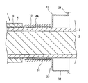
シールド電線1は、図1に示すように、複数の素線を撚った撚線等からなる導体2と、導体2の周囲を覆う絶縁性の合成樹脂等からなる内部絶縁被覆3と、内部絶縁被覆3の周囲に設けられる編組等の導体からなるシールド部4と、シールド部4の周囲を覆う絶縁性の合成樹脂等からなる外部絶縁被覆5と、を有した同軸ケーブルである。一方、接続対象物としてのモータやインバータ、バッテリー等は、その外殻を構成する金属ケース6を有し、金属ケース6には、シールド電線1を挿通させる挿通孔7が設けられている。
シールド電線1は、金属ケース6の外部側(一方側)から挿通孔7を介して内部側(他方側)に挿通されるとともに、内部側の先端部における導体2に端子金具9が固定され、この端子金具9が金属ケース6内の図示しない電気接続部に接続されている。また、シールド電線1のシールド部4は、金属ケース6の外部側において外部絶縁被覆5が除去されて露出されるとともに、後述するシールド部材12及び接続部材11を介して金属ケース6にアース接続されており、これらのシールド部4、接続部材11及びシールド部材12によって電磁波を遮蔽し、接続部からのノイズの漏えいや侵入が防止できるようになっている。
シールドコネクタ10は、シールド電線1を挿通させるとともに金属ケース6の外面に固定される導電性の接続部材11と、シールド電線1のシールド部4と接続部材11とを接続する導電性かつ筒状のシールド部材12と、接続部材11の内面とシールド電線1の内部絶縁被覆3の外面との間に介挿される第一シール部材13と、接続部材11と金属ケース6の挿通孔7の内面との間に介挿される第二シール部材14と、シールド電線1のシールド部4とシールド部材12とを加締めて固定する環状の固定部材としてのシールドパイプ15と、接続部材11を金属ケース6に固定するためのボルト16と、金属ケース6の外部にてシールド電線1を覆う外装部材としてのコルゲートチューブ17と、を備えて構成されている。
接続部材11は、アルミニウム合金等の金属から一体成形されたダイカスト部品であって、金属ケース6の外面に当接して固定される接続部材本体21と、接続部材本体21を貫通してシールド電線1を挿通させる電線案内部22と、接続部材本体21から金属ケース6の挿通孔7内に延びて設けられる筒状の第一延出部23と、接続部材本体21から金属ケース6の外方に延びて設けられる筒状の第二延出部24と、を有して形成されている。第二延出部24の内径は、電線案内部22の内径よりも大きく形成され、この第二延出部24の内周面に密接して第一シール部材13が設けられている。第一延出部23の外周面には、周方向に沿って凹溝状に形成された凹溝部25が形成され、この凹溝部25に第二シール部材14が保持されている。また、接続部材本体21の外周面の複数箇所には、シールド部材12を係止して保持するための係止爪26が設けられている。
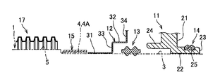
シールド部材12は、導電性の金属材料からなり、金属ケース6の外部側から外面(一方面)に向かって二段に径が大きくなる段付き筒状に形成されている。具体的には、図3にも示すように、シールド部材12は、シールド電線1のシールド部4に接続される第一筒状部31と、この第一筒状部31よりも接続部材11の側(他方側)に位置して径大に設けられる第二筒状部32と、第一筒状部31と第二筒状部32とを連結する段付き部33と、第二筒状部32に連続して折れ曲がり接続部材本体21の外面に沿う鍔状部34と、を有して形成されている。鍔状部34の複数箇所には、金属ケース6に向かって折れ曲がるとともに、接続部材11の係止爪26に係止される被係止部35が設けられている。また、鍔状部34は、接続部材本体21と略同一の外形を有して形成され、接続部材本体21の外面に当接して設けられるとともに、ボルト16で締め付けられることで、シールド部材12が接続部材11に対して接続されている。
第一シール部材13は、図4にも示すように、ゴム等の弾性材料から全体筒状に形成されるとともに、シールド電線1に沿って内部絶縁被覆3の外周面と、接続部材11における第二延出部24の内周面と、に密接するように圧入されている。第一シール部材13の内周面には、二条の環状リップが形成され、これらの環状リップが潰されつつ内部絶縁被覆3の外周面に押しつけられることで、シールド電線1との間がシールされている。また、第一シール部材13の外周面には、二条の環状リップが形成され、これらの環状リップが潰されつつ第二延出部24の内周面に押しつけられることで、接続部材11との間がシールされている。
第二シール部材14は、ゴム等の弾性材料から全体筒状に形成されるとともに、接続部材11の凹溝部25と、金属ケース6の挿通孔7の内面と、に密接するように設けられている。第二シール部材14の内周面には、二条の環状リップが形成され、これらの環状リップが潰されつつ凹溝部25に押しつけられることで、接続部材11との間がシールされている。また、第二シール部材14の外周面には、二条の環状リップが形成され、これらの環状リップが潰されつつ挿通孔7の内周面に押しつけられることで、金属ケース6との間がシールされている。
以上のように接続部材11を介して第一シール部材13及び第二シール部材14によって、シールド電線1の内部絶縁被覆3と、金属ケース6の挿通孔7と、の間がシールされることで、シールド電線1が止水された状態で金属ケース6に接続されるようになっている。また、接続部材11に対して、その係止爪26に被係止部35が係止されるとともに、接続部材本体21の外面に鍔状部34がボルト16で締め付けられることで、シールド部材12が接続されている。この際、シールド部材12の第二筒状部32及び段付き部33は、接続部材11の第二延出部24を覆って設けられ、第二延出部24及び第一シール部材13が外部に露出しないようになっている。さらに、シールド部材12の第一筒状部31は、シールド電線1のシールド部4を露出させた露出部4Aと内部絶縁被覆3との間に挿入されるとともに、シールド部4の外側から加締められるシールドパイプ15によって固定されている。これにより、シールド部4とシールド部材12とが電気的に接続され、従って、シールド部材12及び接続部材11を介してシールド電線1が金属ケース6にアース接続されるようになっている。また、シールド部4の露出部4Aとシールド部材12の第一筒状部31との接続部は、コルゲートチューブ17によって覆われて保護されている。
次に、シールド電線1の金属ケース6への組付け手順の一例を説明する。なお、シールド電線1の組付け手順としては、以下説明するものに限らず、組付け後において図1に示すシールドコネクタ10が構成されていればよいため、以下に示す各手順が適宜に前後してもよい。
先ず、所定長さに切断したシールド電線1の先端部における外部絶縁被覆5を皮剥きしてシールド部4の露出部4Aを露出させるとともに、露出させたシールド部4を適宜な長さだけ切断し、内部絶縁被覆3を露出させておく。このシールド電線1の先端部から内部絶縁被覆3の外面に沿ってシールド部材12を挿通させ、その第一筒状部31をシールド部4の露出部4Aと内部絶縁被覆3との間に挿入してから、シールドパイプ15を露出部4Aの外側から加締めることによって、シールド部材12をシールド電線1に固定するとともに、シールド部4に電気的に接続する。次に、第一シール部材13、接続部材11の順でシールド電線1の先端部から内部絶縁被覆3の外面に沿って挿通させ、第二延出部24の内周面と内部絶縁被覆3との間に第一シール部材13を圧入するとともに、接続部材11の第二延出部24をシールド部材12の第二筒状部32に挿入する。これと同時に、接続部材本体21の外面とシールド部材12の鍔状部34とを当接させるとともに、接続部材11の係止爪26にシールド部材12の被係止部35を係止させ、接続部材11とシールド部材12とを互いに固定する。また、接続部材11の凹溝部25に第二シール部材14を取り付けるとともに、内部絶縁被覆3の先端部を皮剥きして露出させた導体2に端子金具9を圧着しておく。
以上によって、シールド電線1の先端部に接続部材11、シールド部材12、第一シール部材13、第二シール部材14、シールドパイプ15及び端子金具9が取り付けられ、この状態のシールド電線1を端子金具9の側から金属ケース6の挿通孔7に挿通させる。そして、挿通孔7の内周面に第二シール部材14を摺接させつつ接続部材11の第一延出部23を押し込んで挿入し、接続部材本体21を金属ケース6の外面に当接させる。次に、シールド部材12の鍔状部34及び接続部材本体21に挿通させたボルト16を金属ケース6のボルト孔8に螺合し、接続部材11及びシールド部材12を金属ケース6に固定するとともに電気的に接続させる。さらに、シールド電線1の他端側からコルゲートチューブ17を挿通させ、コルゲートチューブ17の先端部を図示しない粘着テープ等でシールド部材12又は接続部材11に固定し、これによって金属ケース6に対するシールド電線1の組付けが完了する。
以上のような本実施形態によれば、シールド電線1におけるシールド部4の露出部4Aと内部絶縁被覆3との間にシールド部材12の第一筒状部31を挿入し、露出部4Aの外側からシールドパイプ15を加締めて固定したことで、シールド部4を折り返さずにシールド部材12と接続できるので、この接続部における径寸法の精度を高めることができる。また、シールド電線1のシールド部4とシールド部材12との接続部が金属ケース6の外側に位置し、この接続部よりもさらに外側において外部絶縁被覆5が除去されているので、接続部材11の電線案内部22には、シールド電線1において外径公差の小さい導体2及び内部絶縁被覆3のみ挿通されることとなり、電線案内部22の内径の精度を高めて内部絶縁被覆3との隙間を小さく形成することができる。従って、シールド電線1を屈曲させるような外力が作用した場合であっても、その内部絶縁被覆3と電線案内部22との間に大きな隙間が形成されることがなく、止水性の低下を防ぐことができる。さらに、電線案内部22の内面と内部絶縁被覆3の外面との間が第一シール部材13でシールされ、金属ケース6の挿通孔7の内面と接続部材11の第一延出部23の外面との間が第二シール部材14でシールされ、これらの各部材間の寸法精度を高めることができるので、止水性能をさらに向上させることができる。
なお、前記実施形態では、シールド電線1として同軸ケーブルを例示したが、複数の芯線からなる導体を有したシールド電線を接続する場合のシールドコネクタ構造としても本発明は利用可能であり、この場合には、シールド部材や第一シール部材、第二シール部材、接続部材の各延出部などが断面楕円形又は断面長円形の筒状に形成されていればよい。また、接続対象物としては、電気自動車やハイブリッド車に用いられるモータやインバータ、バッテリーなどに限らず、その他の適宜な電気機器であってもよいし、内部に電気部品を備えた電気接続箱であってもよい。また、シールド電線をアース接続する対象としては、金属ケース6に限らず、アース接続(グランド接続)用に設けられた部位であってもよい。
1 シールド電線
2 導体
3 内部絶縁被覆
4 シールド部
5 外部絶縁被覆
6 金属ケース(接続対象物)
7 挿通孔
10 シールドコネクタ
11 接続部材
12 シールド部材
13 第一シール部材
14 第二シール部材
15 シールドパイプ(固定部材)
17 コルゲートチューブ(外装部材)
21 接続部材本体
22 電線案内部
23 第一延出部
24 第二延出部
31 第一筒状部
32 第二筒状部
33 段付き部
2 導体
3 内部絶縁被覆
4 シールド部
5 外部絶縁被覆
6 金属ケース(接続対象物)
7 挿通孔
10 シールドコネクタ
11 接続部材
12 シールド部材
13 第一シール部材
14 第二シール部材
15 シールドパイプ(固定部材)
17 コルゲートチューブ(外装部材)
21 接続部材本体
22 電線案内部
23 第一延出部
24 第二延出部
31 第一筒状部
32 第二筒状部
33 段付き部
Claims (4)
- 導体と内部絶縁被覆とシールド部と外部絶縁被覆とを有したシールド電線を、接続対象物の挿通孔に一方から他方へ挿通させて該接続対象物に接続するためのシールドコネクタ構造であって、
前記シールド電線を挿通させるとともに前記接続対象物の一方側に固定される導電性の接続部材と、
前記シールド電線のシールド部と前記接続部材とを接続する導電性かつ筒状のシールド部材と、
前記シールド電線のシールド部を前記シールド部材に固定する環状の固定部材と、
を備え、
前記接続部材は、前記接続対象物の一方面に固定される接続部材本体と、該接続部材本体を貫通して前記シールド電線を一方側から他方側に挿通させる電線案内部と、を有し、
前記シールド部材は、前記接続部材本体の一方面に接続されるシールド接続部と、該シールド接続部から一方側に延びる第一筒状部と、を有して形成され、
前記第一筒状部が前記シールド電線のシールド部と前記内部絶縁被覆との間に挿入され、該シールド部の径方向外側から該第一筒状部に向かって前記固定部材を締め付けることで、前記シールド電線のシールド部と前記シールド部材とが電気的に接続されていることを特徴とするシールドコネクタ構造。 - 前記接続部材には、前記接続部材本体から前記接続対象物の挿通孔内に延びる筒状の第一延出部が形成され、
前記接続部材における前記電線案内部の内面と前記シールド電線の内部絶縁被覆の外面との間に介挿される第一シール部材と、前記接続部材における第一延出部の外面と前記接続対象物の挿通孔の内面との間に介挿される第二シール部材と、をさらに備えたことを特徴とする請求項1に記載のシールドコネクタ構造。 - 前記接続部材には、前記接続部材本体から一方側に延びる筒状の第二延出部が形成され、
前記シールド部材は、前記第一筒状部よりも他方側に位置して径大に設けられる第二筒状部と、該第一筒状部と該第二筒状部とを連結する段付き部と、を有して形成され、
前記第二筒状部及び前記段付き部によって前記接続部材の第二延出部が覆われていることを特徴とする請求項1又は2に記載のシールドコネクタ構造。 - 前記接続部材本体よりも一方側に設けられて前記シールド電線、前記第一筒状部及び前記固定部材を覆う外装部材をさらに備えたことを特徴とする請求項1~3のいずれか一項に記載のシールドコネクタ構造。
Priority Applications (3)
| Application Number | Priority Date | Filing Date | Title |
|---|---|---|---|
| CN201380068158.6A CN104885309A (zh) | 2012-12-25 | 2013-12-25 | 屏蔽连接器结构 |
| DE112013006207.0T DE112013006207T5 (de) | 2012-12-25 | 2013-12-25 | Abschirmverbinderstruktur |
| US14/749,925 US9748704B2 (en) | 2012-12-25 | 2015-06-25 | Shield connector structure |
Applications Claiming Priority (2)
| Application Number | Priority Date | Filing Date | Title |
|---|---|---|---|
| JP2012-280684 | 2012-12-25 | ||
| JP2012280684A JP5990454B2 (ja) | 2012-12-25 | 2012-12-25 | シールドコネクタ構造 |
Related Child Applications (1)
| Application Number | Title | Priority Date | Filing Date |
|---|---|---|---|
| US14/749,925 Continuation US9748704B2 (en) | 2012-12-25 | 2015-06-25 | Shield connector structure |
Publications (1)
| Publication Number | Publication Date |
|---|---|
| WO2014104072A1 true WO2014104072A1 (ja) | 2014-07-03 |
Family
ID=51021150
Family Applications (1)
| Application Number | Title | Priority Date | Filing Date |
|---|---|---|---|
| PCT/JP2013/084608 Ceased WO2014104072A1 (ja) | 2012-12-25 | 2013-12-25 | シールドコネクタ構造 |
Country Status (5)
| Country | Link |
|---|---|
| US (1) | US9748704B2 (ja) |
| JP (1) | JP5990454B2 (ja) |
| CN (1) | CN104885309A (ja) |
| DE (1) | DE112013006207T5 (ja) |
| WO (1) | WO2014104072A1 (ja) |
Families Citing this family (16)
| Publication number | Priority date | Publication date | Assignee | Title |
|---|---|---|---|---|
| US9397430B2 (en) * | 2014-12-01 | 2016-07-19 | Teledyne Instruments, Inc. | Isolated electrical connection assembly and method |
| JP6727951B2 (ja) * | 2016-06-24 | 2020-07-22 | 三菱重工サーマルシステムズ株式会社 | 電動圧縮機の電線導入部構造、これを備えたシールド電線、および電動圧縮機 |
| US10282339B2 (en) * | 2016-09-14 | 2019-05-07 | Apple Inc. | System for presenting electrically supported devices |
| JP6484597B2 (ja) * | 2016-09-26 | 2019-03-13 | 矢崎総業株式会社 | シールドコネクタの止水構造 |
| WO2018194106A1 (ja) * | 2017-04-19 | 2018-10-25 | ダイキン工業株式会社 | ターミナル保護構造を有する圧縮機 |
| JP6567597B2 (ja) * | 2017-05-31 | 2019-08-28 | 矢崎総業株式会社 | シールドコネクタ構造 |
| JP2019033011A (ja) * | 2017-08-09 | 2019-02-28 | 矢崎総業株式会社 | 機器直付用シールドコネクタの取付構造 |
| JP6613282B2 (ja) * | 2017-10-26 | 2019-11-27 | 矢崎総業株式会社 | グロメット及びグロメット組付方法 |
| US10205268B1 (en) * | 2017-12-21 | 2019-02-12 | Aptiv Technologies Limited | Electrical connector having cable seals providing electromagnetic shielding |
| JP6919577B2 (ja) * | 2018-01-16 | 2021-08-18 | 株式会社オートネットワーク技術研究所 | コネクタ |
| DE102018202955A1 (de) * | 2018-02-28 | 2019-08-29 | Robert Bosch Gmbh | Steckverbindersystem und Verfahren zur Herstellung eines Steckverbindersystems |
| US10749281B1 (en) * | 2018-09-04 | 2020-08-18 | Genesis Technology Usa, Inc. | Shear and torque resistant F-connector assembly |
| JP6871227B2 (ja) | 2018-12-27 | 2021-05-12 | 矢崎総業株式会社 | 防水パッキン、防水コネクタ、及びワイヤハーネス |
| JP6876076B2 (ja) * | 2019-01-29 | 2021-05-26 | 矢崎総業株式会社 | コネクタ、及び、ワイヤハーネス |
| WO2021022260A1 (en) * | 2019-08-01 | 2021-02-04 | Ppc Broadband, Inc. | Coupler seal for coaxial cable system components |
| CN110571590A (zh) * | 2019-09-27 | 2019-12-13 | 郑州赛川电子科技有限公司 | 一种单芯过孔连接器 |
Citations (3)
| Publication number | Priority date | Publication date | Assignee | Title |
|---|---|---|---|---|
| JPH05251116A (ja) * | 1992-03-09 | 1993-09-28 | Matsushita Electric Ind Co Ltd | シールド電線の固定装置 |
| JP2000294344A (ja) * | 1999-04-07 | 2000-10-20 | Yazaki Corp | シールドコネクタ構造 |
| JP2001273946A (ja) * | 2000-03-27 | 2001-10-05 | Auto Network Gijutsu Kenkyusho:Kk | シールドコネクタ |
Family Cites Families (12)
| Publication number | Priority date | Publication date | Assignee | Title |
|---|---|---|---|---|
| JP3251540B2 (ja) * | 1997-10-21 | 2002-01-28 | 矢崎総業株式会社 | シールド電線の端末処理構造及び端末処理方法 |
| JP3669560B2 (ja) * | 1999-08-26 | 2005-07-06 | 矢崎総業株式会社 | シールドコネクタのシールド電線接続構造 |
| JP3786594B2 (ja) * | 2001-10-01 | 2006-06-14 | 矢崎総業株式会社 | 電磁波シールド編組 |
| JP4306541B2 (ja) * | 2003-12-22 | 2009-08-05 | 住友電装株式会社 | シールドコネクタ |
| US8029319B2 (en) * | 2007-07-18 | 2011-10-04 | Yazaki Corporation | Shielded connector structure |
| JP4999175B2 (ja) * | 2007-10-03 | 2012-08-15 | 矢崎総業株式会社 | シールドコネクタ |
| JP4970220B2 (ja) * | 2007-11-16 | 2012-07-04 | 矢崎総業株式会社 | シールドコネクタ |
| JP5338562B2 (ja) * | 2009-08-21 | 2013-11-13 | 住友電装株式会社 | シールドコネクタ及びワイヤハーネス |
| JP5467850B2 (ja) * | 2009-12-03 | 2014-04-09 | 矢崎総業株式会社 | L字型コネクタ |
| JP5489691B2 (ja) * | 2009-12-16 | 2014-05-14 | 矢崎総業株式会社 | L字型端子の絶縁構造 |
| JP5485731B2 (ja) * | 2010-02-02 | 2014-05-07 | 矢崎総業株式会社 | 防水型シールドコネクタ |
| JP5622307B2 (ja) * | 2010-07-05 | 2014-11-12 | 矢崎総業株式会社 | シールドコネクタ |
-
2012
- 2012-12-25 JP JP2012280684A patent/JP5990454B2/ja active Active
-
2013
- 2013-12-25 CN CN201380068158.6A patent/CN104885309A/zh active Pending
- 2013-12-25 DE DE112013006207.0T patent/DE112013006207T5/de active Pending
- 2013-12-25 WO PCT/JP2013/084608 patent/WO2014104072A1/ja not_active Ceased
-
2015
- 2015-06-25 US US14/749,925 patent/US9748704B2/en active Active
Patent Citations (3)
| Publication number | Priority date | Publication date | Assignee | Title |
|---|---|---|---|---|
| JPH05251116A (ja) * | 1992-03-09 | 1993-09-28 | Matsushita Electric Ind Co Ltd | シールド電線の固定装置 |
| JP2000294344A (ja) * | 1999-04-07 | 2000-10-20 | Yazaki Corp | シールドコネクタ構造 |
| JP2001273946A (ja) * | 2000-03-27 | 2001-10-05 | Auto Network Gijutsu Kenkyusho:Kk | シールドコネクタ |
Also Published As
| Publication number | Publication date |
|---|---|
| CN104885309A (zh) | 2015-09-02 |
| US9748704B2 (en) | 2017-08-29 |
| DE112013006207T5 (de) | 2015-09-17 |
| US20150295363A1 (en) | 2015-10-15 |
| JP2014127241A (ja) | 2014-07-07 |
| JP5990454B2 (ja) | 2016-09-14 |
Similar Documents
| Publication | Publication Date | Title |
|---|---|---|
| JP5990454B2 (ja) | シールドコネクタ構造 | |
| JP6086381B2 (ja) | コネクタ構造 | |
| JP5886161B2 (ja) | シールドコネクタ構造 | |
| JP6234034B2 (ja) | シールドコネクタ構造 | |
| JP5886159B2 (ja) | シールドコネクタ構造 | |
| JP6043577B2 (ja) | シールドコネクタ | |
| CN103636080B (zh) | 屏蔽电缆固定结构 | |
| US9343821B2 (en) | Terminal waterproofing structure of wire harness | |
| US8680396B2 (en) | Oil-cooled equipment harness | |
| CN102576962B (zh) | 屏蔽连接器 | |
| WO2012099075A1 (ja) | コネクタ | |
| WO2021024781A1 (ja) | ワイヤハーネス | |
| JP7307125B2 (ja) | シールドケーブルの止水構造および止水部品 | |
| JP7497654B2 (ja) | ワイヤハーネス | |
| JP2013123019A (ja) | 電線のシールド構造 | |
| WO2022185948A1 (ja) | 複合ワイヤハーネス |
Legal Events
| Date | Code | Title | Description |
|---|---|---|---|
| 121 | Ep: the epo has been informed by wipo that ep was designated in this application |
Ref document number: 13867974 Country of ref document: EP Kind code of ref document: A1 |
|
| WWE | Wipo information: entry into national phase |
Ref document number: 1120130062070 Country of ref document: DE Ref document number: 112013006207 Country of ref document: DE |
|
| 122 | Ep: pct application non-entry in european phase |
Ref document number: 13867974 Country of ref document: EP Kind code of ref document: A1 |