WO2014103590A1 - アキシャルピストンモータ - Google Patents
アキシャルピストンモータ Download PDFInfo
- Publication number
- WO2014103590A1 WO2014103590A1 PCT/JP2013/081730 JP2013081730W WO2014103590A1 WO 2014103590 A1 WO2014103590 A1 WO 2014103590A1 JP 2013081730 W JP2013081730 W JP 2013081730W WO 2014103590 A1 WO2014103590 A1 WO 2014103590A1
- Authority
- WO
- WIPO (PCT)
- Prior art keywords
- nozzle
- cylinder block
- cylinder
- housing
- hydraulic oil
- Prior art date
- Legal status (The legal status is an assumption and is not a legal conclusion. Google has not performed a legal analysis and makes no representation as to the accuracy of the status listed.)
- Ceased
Links
Images


Classifications
-
- F—MECHANICAL ENGINEERING; LIGHTING; HEATING; WEAPONS; BLASTING
- F03—MACHINES OR ENGINES FOR LIQUIDS; WIND, SPRING, OR WEIGHT MOTORS; PRODUCING MECHANICAL POWER OR A REACTIVE PROPULSIVE THRUST, NOT OTHERWISE PROVIDED FOR
- F03C—POSITIVE-DISPLACEMENT ENGINES DRIVEN BY LIQUIDS
- F03C1/00—Reciprocating-piston liquid engines
- F03C1/02—Reciprocating-piston liquid engines with multiple-cylinders, characterised by the number or arrangement of cylinders
- F03C1/06—Reciprocating-piston liquid engines with multiple-cylinders, characterised by the number or arrangement of cylinders with cylinder axes generally coaxial with, or parallel or inclined to, main shaft axis
- F03C1/0602—Component parts, details
-
- F—MECHANICAL ENGINEERING; LIGHTING; HEATING; WEAPONS; BLASTING
- F03—MACHINES OR ENGINES FOR LIQUIDS; WIND, SPRING, OR WEIGHT MOTORS; PRODUCING MECHANICAL POWER OR A REACTIVE PROPULSIVE THRUST, NOT OTHERWISE PROVIDED FOR
- F03C—POSITIVE-DISPLACEMENT ENGINES DRIVEN BY LIQUIDS
- F03C1/00—Reciprocating-piston liquid engines
- F03C1/02—Reciprocating-piston liquid engines with multiple-cylinders, characterised by the number or arrangement of cylinders
- F03C1/06—Reciprocating-piston liquid engines with multiple-cylinders, characterised by the number or arrangement of cylinders with cylinder axes generally coaxial with, or parallel or inclined to, main shaft axis
- F03C1/0636—Reciprocating-piston liquid engines with multiple-cylinders, characterised by the number or arrangement of cylinders with cylinder axes generally coaxial with, or parallel or inclined to, main shaft axis having rotary cylinder block
- F03C1/0644—Component parts
- F03C1/0652—Cylinders
-
- F—MECHANICAL ENGINEERING; LIGHTING; HEATING; WEAPONS; BLASTING
- F03—MACHINES OR ENGINES FOR LIQUIDS; WIND, SPRING, OR WEIGHT MOTORS; PRODUCING MECHANICAL POWER OR A REACTIVE PROPULSIVE THRUST, NOT OTHERWISE PROVIDED FOR
- F03C—POSITIVE-DISPLACEMENT ENGINES DRIVEN BY LIQUIDS
- F03C1/00—Reciprocating-piston liquid engines
- F03C1/02—Reciprocating-piston liquid engines with multiple-cylinders, characterised by the number or arrangement of cylinders
- F03C1/06—Reciprocating-piston liquid engines with multiple-cylinders, characterised by the number or arrangement of cylinders with cylinder axes generally coaxial with, or parallel or inclined to, main shaft axis
- F03C1/0636—Reciprocating-piston liquid engines with multiple-cylinders, characterised by the number or arrangement of cylinders with cylinder axes generally coaxial with, or parallel or inclined to, main shaft axis having rotary cylinder block
- F03C1/0644—Component parts
- F03C1/0663—Casings, housings
-
- F—MECHANICAL ENGINEERING; LIGHTING; HEATING; WEAPONS; BLASTING
- F03—MACHINES OR ENGINES FOR LIQUIDS; WIND, SPRING, OR WEIGHT MOTORS; PRODUCING MECHANICAL POWER OR A REACTIVE PROPULSIVE THRUST, NOT OTHERWISE PROVIDED FOR
- F03C—POSITIVE-DISPLACEMENT ENGINES DRIVEN BY LIQUIDS
- F03C1/00—Reciprocating-piston liquid engines
- F03C1/02—Reciprocating-piston liquid engines with multiple-cylinders, characterised by the number or arrangement of cylinders
- F03C1/06—Reciprocating-piston liquid engines with multiple-cylinders, characterised by the number or arrangement of cylinders with cylinder axes generally coaxial with, or parallel or inclined to, main shaft axis
- F03C1/0636—Reciprocating-piston liquid engines with multiple-cylinders, characterised by the number or arrangement of cylinders with cylinder axes generally coaxial with, or parallel or inclined to, main shaft axis having rotary cylinder block
- F03C1/0644—Component parts
- F03C1/0668—Swash or actuated plate
-
- F—MECHANICAL ENGINEERING; LIGHTING; HEATING; WEAPONS; BLASTING
- F04—POSITIVE - DISPLACEMENT MACHINES FOR LIQUIDS; PUMPS FOR LIQUIDS OR ELASTIC FLUIDS
- F04B—POSITIVE-DISPLACEMENT MACHINES FOR LIQUIDS; PUMPS
- F04B1/00—Multi-cylinder machines or pumps characterised by number or arrangement of cylinders
- F04B1/12—Multi-cylinder machines or pumps characterised by number or arrangement of cylinders having cylinder axes coaxial with, or parallel or inclined to, main shaft axis
- F04B1/122—Details or component parts, e.g. valves, sealings or lubrication means
-
- F—MECHANICAL ENGINEERING; LIGHTING; HEATING; WEAPONS; BLASTING
- F04—POSITIVE - DISPLACEMENT MACHINES FOR LIQUIDS; PUMPS FOR LIQUIDS OR ELASTIC FLUIDS
- F04B—POSITIVE-DISPLACEMENT MACHINES FOR LIQUIDS; PUMPS
- F04B1/00—Multi-cylinder machines or pumps characterised by number or arrangement of cylinders
- F04B1/12—Multi-cylinder machines or pumps characterised by number or arrangement of cylinders having cylinder axes coaxial with, or parallel or inclined to, main shaft axis
- F04B1/20—Multi-cylinder machines or pumps characterised by number or arrangement of cylinders having cylinder axes coaxial with, or parallel or inclined to, main shaft axis having rotary cylinder block
- F04B1/2014—Details or component parts
- F04B1/2035—Cylinder barrels
-
- F—MECHANICAL ENGINEERING; LIGHTING; HEATING; WEAPONS; BLASTING
- F04—POSITIVE - DISPLACEMENT MACHINES FOR LIQUIDS; PUMPS FOR LIQUIDS OR ELASTIC FLUIDS
- F04B—POSITIVE-DISPLACEMENT MACHINES FOR LIQUIDS; PUMPS
- F04B1/00—Multi-cylinder machines or pumps characterised by number or arrangement of cylinders
- F04B1/12—Multi-cylinder machines or pumps characterised by number or arrangement of cylinders having cylinder axes coaxial with, or parallel or inclined to, main shaft axis
- F04B1/20—Multi-cylinder machines or pumps characterised by number or arrangement of cylinders having cylinder axes coaxial with, or parallel or inclined to, main shaft axis having rotary cylinder block
- F04B1/2014—Details or component parts
- F04B1/2064—Housings
-
- F—MECHANICAL ENGINEERING; LIGHTING; HEATING; WEAPONS; BLASTING
- F04—POSITIVE - DISPLACEMENT MACHINES FOR LIQUIDS; PUMPS FOR LIQUIDS OR ELASTIC FLUIDS
- F04B—POSITIVE-DISPLACEMENT MACHINES FOR LIQUIDS; PUMPS
- F04B1/00—Multi-cylinder machines or pumps characterised by number or arrangement of cylinders
- F04B1/12—Multi-cylinder machines or pumps characterised by number or arrangement of cylinders having cylinder axes coaxial with, or parallel or inclined to, main shaft axis
- F04B1/20—Multi-cylinder machines or pumps characterised by number or arrangement of cylinders having cylinder axes coaxial with, or parallel or inclined to, main shaft axis having rotary cylinder block
- F04B1/2014—Details or component parts
- F04B1/2078—Swash plates
-
- F—MECHANICAL ENGINEERING; LIGHTING; HEATING; WEAPONS; BLASTING
- F04—POSITIVE - DISPLACEMENT MACHINES FOR LIQUIDS; PUMPS FOR LIQUIDS OR ELASTIC FLUIDS
- F04B—POSITIVE-DISPLACEMENT MACHINES FOR LIQUIDS; PUMPS
- F04B53/00—Component parts, details or accessories not provided for in, or of interest apart from, groups F04B1/00 - F04B23/00 or F04B39/00 - F04B47/00
- F04B53/18—Lubricating
Definitions
- This invention relates to an axial piston motor.
- the axial piston motor includes a housing 100, a drive shaft 101 rotatably attached to the housing 100, a cylinder block 102 fixed to the drive shaft 101, and the cylinder block 102.
- a piston 103 fitted in a cylinder 102 a so as to be able to advance and retreat, and a swash plate 104 that supports the piston 103 via a shoe 105 are provided.
- the cylinder block 102 and the drive shaft 101 are rotated by supplying hydraulic oil to the cylinder 102a and reciprocating the piston 103.
- the centrifugal force acting on the piston 103 and the shoe 105 (indicated by arrows) is small, the contact pressure is small and the heat generation amount is small. Therefore, the inner surface of the cylinder 102a can be sufficiently cooled by the hydraulic oil leaking from the clearance only by securing a slight clearance for allowing the hydraulic oil to pass between the cylinder 102a and the piston 103.
- the centrifugal force (indicated by an arrow) affects the contact pressure, and the amount of heat generated on the inner surface of the cylinder 102a increases. Therefore, the working oil leaking from the clearance cannot sufficiently cool the inner surface of the cylinder 102a. Further, when the centrifugal force increases, the piston 103 is pushed radially outward, and the clearance width of the piston 103 radially outward becomes narrower.
- an object of the present invention is to prevent seizure between the piston and the cylinder so that the cylinder block can be operated at a high speed and the performance can be prevented from being deteriorated due to an increase in leakage of hydraulic oil from the cylinder.
- the object is to provide a piston motor.
- an axial piston motor of the present invention is A housing; A drive shaft rotatably attached to the housing; A cylinder block fixed to the drive shaft and having a plurality of cylinders arranged in the circumferential direction; A plurality of pistons fitted in the plurality of cylinders so as to freely advance and retract; A swash plate that supports the plurality of pistons by a surface tiltable with respect to the drive shaft; A nozzle for injecting hydraulic oil is provided on the inner surface of the housing at a position facing the outer peripheral surface of the cylinder block.
- the inner surface of the housing is provided with a nozzle for injecting hydraulic oil at a position facing the outer peripheral surface of the cylinder block.
- seizure between the piston and the cylinder can be prevented, so that the cylinder block can be operated at high speed. Further, since the seizure between the piston and the cylinder can be prevented without increasing the clearance between the piston and the cylinder, it is possible to prevent the performance from being deteriorated due to an increase in the leakage amount of hydraulic oil from the cylinder.
- the outer peripheral surface of the cylinder block has a high temperature region that can be higher than a predetermined threshold during the rotation of the cylinder block,
- the nozzle faces the high temperature region of the cylinder block.
- the threshold value is a value at which seizure can occur between the piston and the cylinder during the rotation of the cylinder block.
- the high temperature region of the cylinder block has a central angle of + 40 ° to ⁇ 40 ° with respect to a position where the piston is at the bottom dead center when viewed from the axial direction of the drive shaft. It is in the setting range.
- the positive direction of the center angle is the rotation direction of the cylinder block.
- this high temperature region is in the set range, this high temperature region is a region where the most seizure can occur. Therefore, seizure can be reliably prevented by the injection of the hydraulic oil from the nozzle.
- the nozzle is disposed on the outer side in the radial direction of the position where the piston is a bottom dead center when viewed from the axial direction of the drive shaft,
- the nozzle ejection direction intersects the set range of the cylinder block as seen from the axial direction of the drive shaft.
- the nozzle is disposed radially outside the position where the piston is at the bottom dead center, and the ejection direction of the nozzle intersects the set range of the cylinder block.
- the nozzle can be placed at an optimal position.
- the plug has the nozzle.
- the nozzle can be easily attached to and detached from the housing by attaching and detaching the plug to the housing. It can be carried out.
- the housing is provided with a pair of main passages connected to the cylinder for supplying and discharging hydraulic oil to and from the cylinder.
- a flushing valve that is switched by the pressure difference between the pair of main passages and guides the hydraulic oil passing through the main passage on the low-pressure side to the nozzle is provided in the housing.
- the motor can be made compact.
- the inner surface of the housing is provided with a nozzle for injecting hydraulic oil at a position facing the outer peripheral surface of the cylinder block.
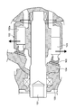
- FIG. 1 is a sectional view showing an axial piston motor according to an embodiment of the present invention.
- the motor includes a housing 1, a drive shaft 3 rotatably attached to the housing 1 via a bearing 2, and a cylinder block 4 fixed to the drive shaft 3.
- the cylinder block 4 has a plurality of cylinders 40 arranged in the circumferential direction.
- a plurality of pistons 5 are fitted in the plurality of cylinders 40 so as to freely advance and retract.
- the tip of the piston 5 is formed in a spherical shape and is connected to the shoe 6.
- the shoe 6 is supported by a swash plate 7 that is positioned relative to the housing 1.
- the swash plate 7 has a surface that can tilt with respect to the drive shaft 3, and supports the plurality of pistons 5 by the inclined surface.
- the inclination angle of the swash plate 7 with respect to the drive shaft 3 is adjusted by the first control piston 81 and the second control piston 82.
- the housing 1 has a cover 10 that covers the end side of the drive shaft 3.
- the cover 10 is provided with a first main passage 11 and a second main passage 12 that are connected to the cylinder 40 and supply and discharge hydraulic fluid to and from the cylinder 40.
- a valve plate 9 is attached to the end face of the cover 10 on the cylinder block 4 side.
- the valve plate 9 has a circular arc-shaped first port 91 and second port 92, and the first port 91 and the second port 92 are formed symmetrically.
- a port 40 a for supplying and discharging hydraulic oil is formed in the cylinder 40 at the bottom of each cylinder 40.
- the end face of the cylinder block 4 is in contact with the valve plate 9.
- the first main passage 11 of the cover 10, the first port 91 of the valve plate 9, and the port 40 a of the predetermined cylinder 40 communicate with each other, the second main passage 12 of the cover 10, The second port 92 of the valve plate 9 communicates with a predetermined port 40a of the cylinder 40.
- the hydraulic fluid When hydraulic fluid is supplied from the first main passage 11, the hydraulic fluid flows into the predetermined cylinder 40 via the first port 91, and reciprocates the piston 5 while moving the cylinder 5.
- the block 4 and the drive shaft 3 are rotated in one direction.
- the hydraulic oil in the cylinder 40 is discharged from the second main passage 12 via the second port 92.
- the pressure in the first main passage 11 on the supply side is higher than the pressure in the second main passage 12 on the discharge side.
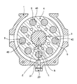
- a nozzle 21 for injecting hydraulic oil is provided on the inner surface of the housing 1 at a position facing the outer peripheral surface of the cylinder block 4.
- the nozzle 21 is provided at the tip of the plug 20.
- the plug 20 is screwed into the housing 1 in a penetrating manner.
- the nozzle 21 communicates with a nozzle passage 15 provided in the housing 1, and the nozzle passage 15 is connected to a flushing valve 30 provided in the cover 10 of the housing 1.
- the flushing valve 30 is connected to the first sub-passage 13 communicating with the first main passage 11 and also connected to the second sub-passage 14 communicating with the second main passage 12.
- the flushing valve 30 is switched by a pressure difference between the first main passage 11 and the second main passage 12, and guides hydraulic oil that passes through the low-pressure main passage to the nozzle 21 through the nozzle passage 15. .
- the outer peripheral surface of the cylinder block 4 has a high temperature region Z that can be higher than a predetermined threshold during the rotation of the cylinder block 4.
- the threshold value is a value at which seizure can occur between the piston 5 and the cylinder 40 during the rotation of the cylinder block 4.
- the high temperature region Z of the cylinder block 4 is within a set range R with a center angle of + 40 ° to ⁇ 40 ° with respect to the position L at which the piston 5 is at the bottom dead center as viewed from the axial direction of the drive shaft 3. .
- the positive direction of the center angle is the rotational direction of the cylinder block 4.
- the bottom dead center of the piston 5 refers to a state in which the piston 5 protrudes most from the cylinder 40.
- the setting range R is a reference line B that connects the center of the piston 5 and the center of the drive shaft 3 as the bottom dead center when viewed from the axial direction of the drive shaft 3.
- the center angle is in the range of + 40 ° to ⁇ 40 °.
- the nozzle 21 faces the high temperature region Z of the cylinder block 4. More specifically, the nozzle 21 is disposed on the radially outer side of the position L where the piston 5 becomes the bottom dead center when viewed from the axial direction of the drive shaft 3.
- the ejection direction of the nozzle 21 intersects the set range R of the cylinder block 4 when viewed from the axial direction of the drive shaft 3. That is, the ejection direction of the nozzle 21 coincides with the radial direction of the cylinder block 4 (the reference line B) as seen from the axial direction of the drive shaft 3.
- FIG. 3 shows a circuit diagram of the motor.
- the first main passage 11 and the second main passage 12 are connected to a motor unit 50 including the drive shaft 3, the cylinder block 4, the piston 5, and the swash plate 7.
- the first sub-passage 13 branched from the first main passage 11 is connected to the first port P1 of the spool 31 of the flushing valve 30, and the second sub-passage 14 branched from the second main passage 12 is connected to the spool 31. Is connected to the second port P2.
- the nozzle passage 15 communicating with the nozzle 21 is connected to the third port P3 of the spool 31.
- the spool 31 has a first position S1, a second position S2, and a third position S3.
- the first position S1 is a neutral position, and the first port P1 and the second port P2 are not connected to the third port P3.
- the second position S2 connects the second port P2 to the third port P3.
- the third position S3 connects the first port P1 to the third port P3.
- the spool 31 When the high-pressure hydraulic oil is supplied to the first main passage 11 and the low-pressure hydraulic oil is discharged from the second main passage 12, the spool 31 is connected to the high-pressure hydraulic oil in the first sub passage 13 and the second hydraulic oil. Due to the differential pressure between the sub passage 14 and the low-pressure hydraulic oil, the first position S 1 is switched to the second position S 2, and the second sub passage 14 communicates with the nozzle passage 15. As a result, the low pressure hydraulic oil in the second sub-passage 14 can be injected from the nozzle 21 to the motor unit 50.
- the spool 31 is connected to the high pressure hydraulic oil in the second sub passage 14 and the first hydraulic oil.
- the first sub-path 13 is communicated with the nozzle path 15 by switching from the first position S1 to the third position S3 due to the pressure difference between the sub-path 13 and the low-pressure hydraulic oil.
- the low pressure hydraulic oil in the first sub-passage 13 can be injected from the nozzle 21 to the motor unit 50.
- hydraulic oil is branched from the first sub-passage 13 and the second sub-passage 14 and flows into the first and second control pistons 81 and 82 (shown in FIG. 1). , 82 may be driven.
- FIG. 4 shows a cross-sectional view of the flushing valve 30.
- the spool 31 is slidably fitted into a valve hole 32 provided in the cover 10 of the housing 1. Then, when high pressure hydraulic oil is supplied to the first sub-passage 13 as indicated by the solid line arrow, the spool 31 receives the high pressure hydraulic oil, and the right side in the drawing (second line in FIG. 3). Move to position S2), and low pressure hydraulic oil is supplied from the second sub-passage 14 to the nozzle passage 15 as indicated by the dotted arrow.
- the nozzle 21 for injecting hydraulic oil is provided on the inner surface of the housing 1 at a position facing the outer peripheral surface of the cylinder block 4.
- seizure between the piston 5 and the cylinder 40 can be prevented, so that the cylinder block 4 can be operated at high speed.
- seizure between the piston 5 and the cylinder 40 can be prevented without increasing the clearance between the piston 5 and the cylinder 40, thereby preventing a decrease in performance due to an increase in the amount of hydraulic fluid leakage from the cylinder 40. it can.
- nozzle 21 is opposed to the high temperature region Z of the cylinder block 4, hydraulic oil can be sprayed from the nozzle 21 to the high temperature region Z, and seizure between the piston 5 and the cylinder 40 is ensured. Can be prevented.
- the high temperature region Z is in the set range R, the high temperature region Z is a region where burn-in can occur most. Therefore, the burning of the hydraulic oil from the nozzle 21 can surely prevent seizure.
- the nozzle 21 is disposed radially outside the position L where the piston 5 is the bottom dead center, and the ejection direction of the nozzle 21 intersects the set range R of the cylinder block 4. Can be placed in an optimal position.
- the plug 20 is screwed into the housing 1 and the plug 20 has the nozzle 21, so that the nozzle 21 can be easily attached to and detached from the housing 1 by attaching and detaching the plug 20 to the housing 1. be able to.
- the flushing valve 30 is provided in the housing 1, the motor can be made compact.
- the present invention is not limited to the above-described embodiment.
- the number of pistons 5 and cylinders 40 can be increased or decreased.
- the number of nozzles 21 can be freely increased or decreased.
- the set range R of the cylinder block 4 has a center angle in the range of + 40 ° to ⁇ 40 ° with the reference line B as the center. May be in the range of + 15 ° to ⁇ 15 °.
- the ejection direction of the nozzle 21 coincides with the radial direction of the cylinder block 4 when viewed from the axial direction of the drive shaft 3, but the ejection direction of the nozzle 21 is in the set range R. As long as they intersect, the cylinder block 4 may be inclined in the radial direction.
- the specific numerical value of the setting range R is not limited to this embodiment, and the design can be changed.
- the ejection direction of the said nozzle 21 corresponds in the plane (radial direction) orthogonal to the axis
- the ejection direction of the nozzle 21 may be tilted in a range ⁇ of + 45 ° to ⁇ 45 ° with reference to the direction S perpendicular to the axis of the drive shaft 3.
- the nozzle 21 is a part of the plug 20, but it may be formed directly on the housing 1.
- the nozzle may be opposed to a region other than the high temperature region.
- the high temperature region may have a center angle other than + 40 ° to ⁇ 40 °. You may arrange
- the flushing valve may be omitted.
Landscapes
- Engineering & Computer Science (AREA)
- Mechanical Engineering (AREA)
- General Engineering & Computer Science (AREA)
- Chemical & Material Sciences (AREA)
- Combustion & Propulsion (AREA)
- Hydraulic Motors (AREA)
- Reciprocating Pumps (AREA)
- Lubrication Of Internal Combustion Engines (AREA)
Priority Applications (5)
| Application Number | Priority Date | Filing Date | Title |
|---|---|---|---|
| US14/378,421 US20150000513A1 (en) | 2012-12-27 | 2013-11-26 | Axial piston motor |
| KR1020147027049A KR20140126769A (ko) | 2012-12-27 | 2013-11-26 | 액셜 피스톤 모터 |
| EP13868490.7A EP2940291A1 (en) | 2012-12-27 | 2013-11-26 | Axial piston motor |
| IN7165DEN2014 IN2014DN07165A (https=) | 2012-12-27 | 2013-11-26 | |
| CN201380033130.9A CN104379923A (zh) | 2012-12-27 | 2013-11-26 | 轴向柱塞马达 |
Applications Claiming Priority (2)
| Application Number | Priority Date | Filing Date | Title |
|---|---|---|---|
| JP2012-285032 | 2012-12-27 | ||
| JP2012285032A JP2014126020A (ja) | 2012-12-27 | 2012-12-27 | アキシャルピストンモータ |
Publications (1)
| Publication Number | Publication Date |
|---|---|
| WO2014103590A1 true WO2014103590A1 (ja) | 2014-07-03 |
Family
ID=51020684
Family Applications (1)
| Application Number | Title | Priority Date | Filing Date |
|---|---|---|---|
| PCT/JP2013/081730 Ceased WO2014103590A1 (ja) | 2012-12-27 | 2013-11-26 | アキシャルピストンモータ |
Country Status (7)
| Country | Link |
|---|---|
| US (1) | US20150000513A1 (https=) |
| EP (1) | EP2940291A1 (https=) |
| JP (1) | JP2014126020A (https=) |
| KR (1) | KR20140126769A (https=) |
| CN (1) | CN104379923A (https=) |
| IN (1) | IN2014DN07165A (https=) |
| WO (1) | WO2014103590A1 (https=) |
Families Citing this family (4)
| Publication number | Priority date | Publication date | Assignee | Title |
|---|---|---|---|---|
| JP6206513B2 (ja) * | 2016-01-14 | 2017-10-04 | 株式会社豊田自動織機 | 可変容量型斜板式ピストンポンプ |
| JP6984825B2 (ja) | 2017-01-13 | 2021-12-22 | 学校法人 関西大学 | 金属元素含有ナノ粒子を用いたヒドロシリル化による有機ケイ素化合物の製造方法 |
| JP7476060B2 (ja) * | 2020-09-14 | 2024-04-30 | 株式会社小松製作所 | バルブプレート、シリンダブロック、油圧モータ |
| US11994117B2 (en) * | 2021-10-04 | 2024-05-28 | Hamilton Sundstrand Corporation | Variable positive displacement pump actuator systems |
Citations (7)
| Publication number | Priority date | Publication date | Assignee | Title |
|---|---|---|---|---|
| JPS5549162A (en) * | 1978-10-03 | 1980-04-09 | Ikeuchi:Kk | Mist producting device |
| JPS5521187B2 (https=) * | 1972-03-29 | 1980-06-07 | ||
| JP2000246153A (ja) * | 1999-03-03 | 2000-09-12 | Kuroda Precision Ind Ltd | 液体微粒化装置 |
| JP2002098034A (ja) * | 2000-09-26 | 2002-04-05 | Sanwa Seiki Co Ltd | 油圧モータ |
| JP2002242824A (ja) * | 2001-02-14 | 2002-08-28 | Sauer-Danfoss-Daikin Ltd | 液圧ピストンポンプ及びそれを用いた静液圧式変速機 |
| JP2011214429A (ja) * | 2010-03-31 | 2011-10-27 | Kawasaki Heavy Ind Ltd | バルブプレート、並びにこれを備えたアキシャルピストン式油圧ポンプ・モータ |
| JP4828371B2 (ja) | 2006-10-23 | 2011-11-30 | ボッシュ・レックスロス株式会社 | アキシャルピストンポンプ・モータ |
Family Cites Families (7)
| Publication number | Priority date | Publication date | Assignee | Title |
|---|---|---|---|---|
| JPS5521187A (en) * | 1978-08-03 | 1980-02-15 | Mitsubishi Electric Corp | Semiconductor device |
| JP3932659B2 (ja) * | 1998-03-30 | 2007-06-20 | 株式会社豊田自動織機 | 圧縮機における冷媒吸入構造 |
| JP4050899B2 (ja) * | 2001-12-21 | 2008-02-20 | ユニクラ インターナショナル リミテッド | 斜板式圧縮機およびそのハウジング |
| FR2891863B1 (fr) * | 2005-10-11 | 2010-10-08 | Inst Francais Du Petrole | Procede pour eliminer le carburant contenu dans de l'huile de lubrification d'un moteur a combustion interne et moteur utilisant un tel procede |
| DE102009056518A1 (de) * | 2009-12-02 | 2011-06-09 | Bock Kältemaschinen GmbH | Verdichter |
| US8500418B2 (en) * | 2010-10-28 | 2013-08-06 | Spx Corporation | Internally supplied air jet cooling for a hydraulic pump |
| US20130000481A1 (en) * | 2010-11-16 | 2013-01-03 | Kawasaki Jukogyo Kabushiki Kaisha | Cooling structure of cylinder block and swash plate type liquid-pressure apparatus including same |
-
2012
- 2012-12-27 JP JP2012285032A patent/JP2014126020A/ja active Pending
-
2013
- 2013-11-26 CN CN201380033130.9A patent/CN104379923A/zh active Pending
- 2013-11-26 EP EP13868490.7A patent/EP2940291A1/en not_active Withdrawn
- 2013-11-26 US US14/378,421 patent/US20150000513A1/en not_active Abandoned
- 2013-11-26 WO PCT/JP2013/081730 patent/WO2014103590A1/ja not_active Ceased
- 2013-11-26 KR KR1020147027049A patent/KR20140126769A/ko not_active Ceased
- 2013-11-26 IN IN7165DEN2014 patent/IN2014DN07165A/en unknown
Patent Citations (7)
| Publication number | Priority date | Publication date | Assignee | Title |
|---|---|---|---|---|
| JPS5521187B2 (https=) * | 1972-03-29 | 1980-06-07 | ||
| JPS5549162A (en) * | 1978-10-03 | 1980-04-09 | Ikeuchi:Kk | Mist producting device |
| JP2000246153A (ja) * | 1999-03-03 | 2000-09-12 | Kuroda Precision Ind Ltd | 液体微粒化装置 |
| JP2002098034A (ja) * | 2000-09-26 | 2002-04-05 | Sanwa Seiki Co Ltd | 油圧モータ |
| JP2002242824A (ja) * | 2001-02-14 | 2002-08-28 | Sauer-Danfoss-Daikin Ltd | 液圧ピストンポンプ及びそれを用いた静液圧式変速機 |
| JP4828371B2 (ja) | 2006-10-23 | 2011-11-30 | ボッシュ・レックスロス株式会社 | アキシャルピストンポンプ・モータ |
| JP2011214429A (ja) * | 2010-03-31 | 2011-10-27 | Kawasaki Heavy Ind Ltd | バルブプレート、並びにこれを備えたアキシャルピストン式油圧ポンプ・モータ |
Also Published As
| Publication number | Publication date |
|---|---|
| JP2014126020A (ja) | 2014-07-07 |
| US20150000513A1 (en) | 2015-01-01 |
| EP2940291A1 (en) | 2015-11-04 |
| KR20140126769A (ko) | 2014-10-31 |
| CN104379923A (zh) | 2015-02-25 |
| IN2014DN07165A (https=) | 2015-04-24 |
Similar Documents
| Publication | Publication Date | Title |
|---|---|---|
| US9175672B2 (en) | Valve plate and axial piston hydraulic pump motor including the same | |
| JP3861638B2 (ja) | 可変容量形ポンプ | |
| WO2016006465A1 (ja) | 水圧回転機 | |
| US10145367B2 (en) | Piston pump and valve plate of piston pump | |
| JP5444462B2 (ja) | シリンダブロックの冷却構造、及びそれを有する斜板形液圧装置 | |
| CN103459842A (zh) | 斜轴式轴向活塞泵·马达 | |
| WO2014103590A1 (ja) | アキシャルピストンモータ | |
| WO2011052512A1 (ja) | アキシャルピストン型液圧回転機械 | |
| JP2010174690A (ja) | バルブプレート、及びそれを備えるピストンポンプ又はモータ | |
| US20160333867A1 (en) | Sliding Shoe for a Hydrostatic Axial Piston Machine | |
| CN104141593B (zh) | 具有气缸筒的流体静力学的轴向活塞机 | |
| US9611848B2 (en) | Variable displacement vane pump having connection groove communicating with suction-side back pressure port thereof | |
| CN103562544A (zh) | 液压静力的径向活塞机和用于液压静力的径向活塞机的活塞 | |
| CN109891093B (zh) | 缸体及具备该缸体的斜板型液压旋转装置 | |
| US9644480B2 (en) | Fluid pressure rotary machine | |
| JP6280783B2 (ja) | 水圧回転機 | |
| JP6246582B2 (ja) | 液圧回転機械 | |
| JP6913260B2 (ja) | シリンダブロックとそれを備えた斜板形液圧回転装置 | |
| KR102861444B1 (ko) | 유압 펌프 및 건설 기계 | |
| KR20100049143A (ko) | 사판의 과경전 방지장치가 구비된 유체기계 |
Legal Events
| Date | Code | Title | Description |
|---|---|---|---|
| WWE | Wipo information: entry into national phase |
Ref document number: 14378421 Country of ref document: US |
|
| 121 | Ep: the epo has been informed by wipo that ep was designated in this application |
Ref document number: 13868490 Country of ref document: EP Kind code of ref document: A1 |
|
| ENP | Entry into the national phase |
Ref document number: 20147027049 Country of ref document: KR Kind code of ref document: A |
|
| WWE | Wipo information: entry into national phase |
Ref document number: 2013868490 Country of ref document: EP |
|
| NENP | Non-entry into the national phase |
Ref country code: DE |