WO2014103457A1 - レンズ駆動装置 - Google Patents
レンズ駆動装置 Download PDFInfo
- Publication number
- WO2014103457A1 WO2014103457A1 PCT/JP2013/076682 JP2013076682W WO2014103457A1 WO 2014103457 A1 WO2014103457 A1 WO 2014103457A1 JP 2013076682 W JP2013076682 W JP 2013076682W WO 2014103457 A1 WO2014103457 A1 WO 2014103457A1
- Authority
- WO
- WIPO (PCT)
- Prior art keywords
- terminal
- base
- leaf spring
- fixing
- lens
- Prior art date
- Legal status (The legal status is an assumption and is not a legal conclusion. Google has not performed a legal analysis and makes no representation as to the accuracy of the status listed.)
- Ceased
Links
Images


Classifications
-
- G—PHYSICS
- G02—OPTICS
- G02B—OPTICAL ELEMENTS, SYSTEMS OR APPARATUS
- G02B7/00—Mountings, adjusting means, or light-tight connections, for optical elements
- G02B7/02—Mountings, adjusting means, or light-tight connections, for optical elements for lenses
- G02B7/026—Mountings, adjusting means, or light-tight connections, for optical elements for lenses using retaining rings or springs
-
- G—PHYSICS
- G02—OPTICS
- G02B—OPTICAL ELEMENTS, SYSTEMS OR APPARATUS
- G02B7/00—Mountings, adjusting means, or light-tight connections, for optical elements
- G02B7/02—Mountings, adjusting means, or light-tight connections, for optical elements for lenses
- G02B7/04—Mountings, adjusting means, or light-tight connections, for optical elements for lenses with mechanism for focusing or varying magnification
- G02B7/08—Mountings, adjusting means, or light-tight connections, for optical elements for lenses with mechanism for focusing or varying magnification adapted to co-operate with a remote control mechanism
-
- G—PHYSICS
- G02—OPTICS
- G02B—OPTICAL ELEMENTS, SYSTEMS OR APPARATUS
- G02B7/00—Mountings, adjusting means, or light-tight connections, for optical elements
- G02B7/02—Mountings, adjusting means, or light-tight connections, for optical elements for lenses
- G02B7/04—Mountings, adjusting means, or light-tight connections, for optical elements for lenses with mechanism for focusing or varying magnification
- G02B7/10—Mountings, adjusting means, or light-tight connections, for optical elements for lenses with mechanism for focusing or varying magnification by relative axial movement of several lenses, e.g. of varifocal objective lens
-
- G—PHYSICS
- G03—PHOTOGRAPHY; CINEMATOGRAPHY; ANALOGOUS TECHNIQUES USING WAVES OTHER THAN OPTICAL WAVES; ELECTROGRAPHY; HOLOGRAPHY
- G03B—APPARATUS OR ARRANGEMENTS FOR TAKING PHOTOGRAPHS OR FOR PROJECTING OR VIEWING THEM; APPARATUS OR ARRANGEMENTS EMPLOYING ANALOGOUS TECHNIQUES USING WAVES OTHER THAN OPTICAL WAVES; ACCESSORIES THEREFOR
- G03B3/00—Focusing arrangements of general interest for cameras, projectors or printers
- G03B3/10—Power-operated focusing
-
- G—PHYSICS
- G03—PHOTOGRAPHY; CINEMATOGRAPHY; ANALOGOUS TECHNIQUES USING WAVES OTHER THAN OPTICAL WAVES; ELECTROGRAPHY; HOLOGRAPHY
- G03B—APPARATUS OR ARRANGEMENTS FOR TAKING PHOTOGRAPHS OR FOR PROJECTING OR VIEWING THEM; APPARATUS OR ARRANGEMENTS EMPLOYING ANALOGOUS TECHNIQUES USING WAVES OTHER THAN OPTICAL WAVES; ACCESSORIES THEREFOR
- G03B5/00—Adjustment of optical system relative to image or object surface other than for focusing
-
- H—ELECTRICITY
- H02—GENERATION; CONVERSION OR DISTRIBUTION OF ELECTRIC POWER
- H02K—DYNAMO-ELECTRIC MACHINES
- H02K41/00—Propulsion systems in which a rigid body is moved along a path due to dynamo-electric interaction between the body and a magnetic field travelling along the path
- H02K41/02—Linear motors; Sectional motors
- H02K41/035—DC motors; Unipolar motors
- H02K41/0352—Unipolar motors
- H02K41/0354—Lorentz force motors, e.g. voice coil motors
- H02K41/0356—Lorentz force motors, e.g. voice coil motors moving along a straight path
-
- G—PHYSICS
- G03—PHOTOGRAPHY; CINEMATOGRAPHY; ANALOGOUS TECHNIQUES USING WAVES OTHER THAN OPTICAL WAVES; ELECTROGRAPHY; HOLOGRAPHY
- G03B—APPARATUS OR ARRANGEMENTS FOR TAKING PHOTOGRAPHS OR FOR PROJECTING OR VIEWING THEM; APPARATUS OR ARRANGEMENTS EMPLOYING ANALOGOUS TECHNIQUES USING WAVES OTHER THAN OPTICAL WAVES; ACCESSORIES THEREFOR
- G03B2205/00—Adjustment of optical system relative to image or object surface other than for focusing
- G03B2205/0053—Driving means for the movement of one or more optical element
Definitions
- the present invention relates to a lens driving device mounted on an electronic apparatus having a function of capturing an image or a video, and in particular, is provided in a lens holder that holds a lens barrel, and the lens holder is fixed to a fixed portion including a base member.
- the present invention relates to a leaf spring that is displaceably supported in the optical axis direction.
- Such a small camera unit is illustratively composed of a lens driving device including a driving mechanism including a lens and a sensor substrate including an element such as an image sensor. Further, in the lens driving device, since the current is supplied to the coil that is a component of the driving mechanism, the coil and the sensor substrate are electrically connected. In addition, a power supply terminal for supplying current to the coil is provided from the sensor substrate side.
- Various techniques have been proposed for connection between the lens driving device and the sensor substrate side.
- Japanese Patent Laid-Open No. 2004-228561 includes a movable part that has a movable lens and moves in the optical axis direction with respect to the lens barrel, and a linear that has a drive magnet and a drive coil and moves the movable part in the optical axis direction.
- An actuator a holding portion for holding the movable portion, a pair of biasing leaf springs having a plurality of spring portions for biasing the movable portion in the optical axis direction, and a mounted portion attached to the lens barrel, are provided.
- One of the urging plate springs is constituted by two spring members, and the two spring members are provided with a coil connection portion connected to both ends of the drive coil and a connection terminal portion for energizing the drive coil, respectively.
- a lens driving device has been proposed.
- connection terminal portion is provided on a leaf spring, bent about 90 ° with respect to the attached portion, and protrudes rearward (sensor substrate side).
- Patent Document 2 proposes a configuration in which a terminal is provided on the base member of the lens driving device, and the leaf spring and the substrate side are electrically connected via the terminal. In Patent Document 2, it is proposed to connect the end face of the leaf spring and the end face of the terminal by soldering.
- Japanese Patent Publication Japanese Patent Laid-Open No. 2006-251216 (published on September 21, 2006)” Japanese Patent Publication “JP 2011-102823 (published May 26, 2011)”
- the lens driving device described in Patent Document 1 has a leaf spring bent to serve as a power supply terminal, and its thickness is several tens of microns like the leaf spring. Connection with was difficult.
- the terminal and the leaf spring are connected by soldering, and the end surface of the leaf spring and the end surface of the terminal are connected by soldering. There was a problem that it was difficult to obtain.
- the present invention has been made in view of the above problems, and an object of the present invention is to provide a lens driving device capable of more reliably connecting a leaf spring and a terminal.
- a lens driving device includes a movable body that holds a lens and is movable in the optical axis direction of the lens, and drives the movable body in the optical axis direction. And a base spring to which the movable body is movably supported in the direction of the optical axis, and a base portion to which the leaf spring is attached.
- the drive mechanism is for driving attached to the movable body.
- the base has a terminal for supplying current to the drive coil; and the leaf spring is fixed to the movable body and electrically connected to the drive coil.
- a movable body fixing portion having a connection portion connected to the base portion, a base portion fixing portion fixed to the base portion, an arm portion connecting the movable body fixing portion and the base portion fixing portion, and the terminal.
- Terminal connection and base fixing Connecting with said terminal connecting portion and has a resilient portion for biasing the terminal connection portion to the terminal.
- the leaf spring has a base fixing portion and a terminal connection portion, and the base fixing portion and the terminal connection portion are connected by an elastic portion, whereby the leaf spring and the terminal are connected. It is possible to stably perform electrical connection.
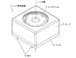
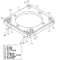
- FIG. 2 is a perspective view of a lens driving device according to an embodiment (first embodiment) of the present invention.
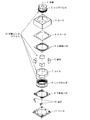
- FIG. 3 is an exploded perspective view of the lens driving device.
- the lens driving device 1 is for moving the lens barrel 2 in the direction of the optical axis L.
- the lens driving device 1 is illustratively a VCM type lens driving device using a voice coil motor (VCM) as a driving source (driving method).
- VCM voice coil motor
- the lens driving device 1 is combined with a sensor substrate (not shown) and an image sensor (not shown) to constitute a camera module.
- a camera module is mounted on an electronic device such as a mobile phone or a tablet PC (Personal Computer).
- the lens driving device 1 is formed in a substantially quadrangular prism shape.
- the lens driving device 1 generally includes a yoke 3 for storing various components such as a lens barrel 2, a base 11 serving as a base for attachment to a sensor substrate, and two terminals 10. It is.
- the subject direction of the optical axis L of the lens driving device 1 is the “up” direction, and the direction opposite to the subject direction is the “down” direction.
- a plane perpendicular to the optical axis L is a horizontal plane.
- a surface to which the two terminals 10 are attached is referred to as a front surface, and a surface that faces the surface to which the two terminals 10 are attached is referred to as a back surface.
- the direction perpendicular to the front and back normal lines and the optical axis L is defined as the left-right direction.
- the yoke 3 constitutes the upper surface of the lens driving device 1 and most of the side surfaces. That is, the yoke 3 is used not only to form a magnetic circuit with the magnet 6 described later, but also as a cover member for housing the internal mechanism of the lens driving device 1.
- the four side surfaces of the yoke 3 are illustratively configured such that the opposing side surfaces are substantially parallel.
- a circular opening is provided on the upper surface of the yoke 3 so that the lens barrel 2 and the like are exposed to the outside (for example, a subject).
- the yoke 3 is provided so as to cover the upper part of the base 11. Note that the shape of the yoke 3 shown in FIG. 2 is merely an example, and can be modified in accordance with the shape of the internal mechanism housed in the yoke 3.
- the base 11 constitutes the bottom surface and a part of the side surface of the lens driving device 1.
- a sensor substrate (not shown) is disposed below the base 11. As shown in FIG. 3, the base 11 is opened to allow light incident through the lens barrel 2 to pass therethrough.
- Two terminals 10 are attached to the base 11.
- the two terminals 10 are provided apart from each other at the end of one side of the base 11.
- the two terminals 10 are electrically connected to a sensor board disposed at the lower part of the base 11.
- the sensor board is equipped with electronic parts such as an image sensor and a clock source.
- the image sensor is disposed on the sensor substrate below the lens barrel 2 and on the optical axis L, and converts light incident through the lens barrel 2 into an electrical signal.
- the image pickup device is configured by, for example, a charge coupled device (CCD) image sensor, a complementary metal oxide (CMOS) image sensor, or the like.
- the yoke 3 and the base 11 are illustratively configured to be substantially square when viewed from above and below.
- the spacer 4 the upper leaf spring 5, the movable lens unit 12, and the lower leaf spring 9 are housed in the yoke 3 of the lens driving device 1 in order from the top to the bottom.
- the upper leaf spring 5 and the lower leaf spring 9 are collectively referred to as “a pair of leaf springs 5 and 9” without being distinguished from each other.
- the movable lens unit 12 is arranged on the lens barrel 2, the lens holder 8 that holds the lens barrel 2, the drive coil 7 that is fixed so as to be positioned on the outer periphery of the lens holder 8, and the outer periphery of the drive coil 7. Magnet 6.
- the lens holder 8 is a cylindrical member for holding the lens barrel 2.
- the lens holder 8 is exemplarily formed so that the shape of the inner peripheral surface when viewed from the vertical direction is a substantially circular shape, and the shape of the outer peripheral surface when viewed from the vertical direction is a substantially regular octagon. .
- the driving coil 7 is electrically connected to the lower leaf spring 9 (details will be described later), receives power from the lower leaf spring 9 and generates a driving force for the movable lens unit 12 by the action of the magnet 6.
- the shape of the drive coil 7 is illustratively a cylinder that is slightly larger than the lens holder 8 so as to surround the outer periphery of the lens holder 8. Further, the drive coil 7 is formed so that the upper and lower ends thereof are substantially octagonal when viewed from the vertical direction.
- the magnet 6 is illustratively composed of four substantially triangular prism-shaped members. These four members are arranged in a space formed between the side surface of the yoke 3 and the outer periphery of the coil 7. That is, the four members are arranged so as to face two diagonal lines of the yoke 3.
- a pair of leaf springs 5 and 9 are provided on both sides of the lens holder 8 in the optical axis direction.
- the pair of leaf springs 5 and 9 support the lens holder 8 so as to be displaceable in the optical axis direction while being positioned in the radial direction.
- the upper leaf spring 5 is fixed to the spacer 4 at the outer peripheral frame.
- the spacer 4 is fixed to the inner upper surface of the yoke 3.
- the upper leaf spring 5 and the lower leaf spring 9 are made of a conductive metal such as stainless steel or beryllium copper, for example.
- the upper leaf spring 5 and the lower leaf spring 9 are manufactured by pressing a predetermined thin plate or etching using a photolithography technique.
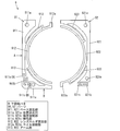
- the lower leaf spring 9 is composed of two parts 91 and 92.
- the parts 91 and 92 First, a common configuration between the parts 91 and 92 will be described focusing on the part 91.
- the reference numerals in parentheses indicate the corresponding member numbers of the parts 92.
- the part 91 (92) includes a base fixing portion 911 (921) fixed to the base 11, a lens holder fixing portion 912 (922) for fixing the lens holder 8 (that is, the movable lens unit 12), and two arm portions. 913 (923).
- the base fixing part 911 (921) and the lens holder fixing part 912 (922) are connected by two arm parts 913 (923).
- the base fixing portion 911 (921) is provided with a positioning hole 911a (921a) and a terminal connection portion 911b (921b), respectively.
- the terminal connection portion 911b (921b) has a shape with a bifurcated tip.
- the lens holder fixing portion 912 (922) is illustratively formed in an arc shape according to the shape of the lower end of the lens holder 8. Further, the lens holder fixing portion 912 (922) is provided with a coil connection portion 912a (922a) at one end thereof.
- the base fixing portion 911 (921) is fixed to the base 11, and the lens holder fixing portion 912 (922) is fixed to the lower end of the lens holder 8.
- the coil 7 fixed to the lens holder 8 is aligned with the two coil connection portions 912a and 922a of the lower leaf spring 9 at the lower end, and is soldered to the two coil connection portions 912a and 922a of the lower leaf spring 9. Connected by attaching. Therefore, at the lower end of the coil 7, the contact points with the coil connecting portions 912a and 922a are in a positional relationship facing each other.
- a terminal connection portion 911b is provided between the two arm portions 913 in the base fixing portion 911.
- the terminal connection portion 911b is located on the inner side of a closed path composed of the base fixing portion 911, the lens holder fixing portion 912, and the two arm portions 913, in a direction from the front surface to the rear surface in the substantially long side direction of the base fixing portion 911. It is formed to protrude.
- An elastic portion 911c is provided in the vicinity (both ends) of the terminal connection portion 911b.
- the base fixing portion 911 includes a long side portion A and a short side portion B, and one of both ends of the terminal connection portion 911b is connected to the long side portion A by the elastic portion 911c (A), and the other side. Is connected to the short side portion B by the elastic portion 911c (B).
- the elastic portion 911c may be provided with a cut portion as shown in FIG. 4 in order to further apply a biasing force.
- the terminal connection portion 921b is provided at the end of the base fixing portion 921. That is, the terminal connection portion 921b is provided at a position outside the two arm portions 923. In other words, the terminal connection portion 921b is provided outside the closed circuit including the base fixing portion 921, the lens holder fixing portion 922, and the two arm portions 923. Further, the terminal connection portion 921b is formed in the direction of the substantially short side of the base fixing portion 921 toward the outside (the direction opposite to the part 91). An elastic portion 921c is provided at one end of the terminal connection portion 921b.
- the shape of the part 91 (92) described above is exemplary, and can be appropriately modified according to the shapes of the movable lens unit 12, the terminal 10, and the base 11.
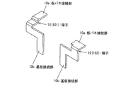
- each of the two terminals 10 is each fixed at a predetermined position on the base 11. As shown in FIG. 5, each of the two terminals 10 includes a leaf spring connecting portion 10a and a substrate connecting portion 10b, and the leaf spring connecting portion 10a and the substrate connecting portion 10b are connected substantially vertically.
- the leaf spring connecting portion 10a is electrically connected to the terminal connecting portion 911b or 921b of the lower leaf spring 9.
- the board connecting part 10b is electrically connected to a terminal on the sensor board (not shown) side.
- the two terminals 10 are illustratively configured asymmetrically in shape and length in accordance with the shape of the base 11.
- the left terminal of the lens driving device 1 is the first terminal 101
- the right terminal of the lens driving device 1 is the second terminal 102.
- the first terminal 101 and the second terminal 102 are configured as follows.
- the leaf spring connecting portion 10a has a configuration in which a step is provided in the vertical direction.
- the board connecting portion 10b is L-shaped.
- the shape of the leaf spring connecting portion 10a is configured as a flat plate.
- substrate connection part 10b is a crank type (in other words, S shape).
- the first terminal 101 and the second terminal 102 can be brought into surface contact with the terminal connection part 911b of the part 91 and the 921b of the part 92 because the leaf spring connection part 10a has a plate shape.
- the base 11 schematically includes four leaf spring fixing portions 11 a for fixing the lower leaf spring 9, two terminal insertion holes 11 c into which the terminals 10 are inserted, and the terminals 10. And two terminal fixing portions 11d for installing the device.
- Each leaf spring fixing portion 11a is provided with a boss 11b.
- the base 11 includes a first base 111 to which the part 91 and the first terminal 101 are fixed, and a second base 112 to which the part 92 and the second terminal 102 are fixed. Furthermore, it can be said that the first base 111 and the second base 112 correspond to one and the other when the base 11 is divided into two at the center in the left-right direction.
- the first base 111 has two leaf spring fixing portions 11a, one terminal insertion hole 11c, and one terminal fixing portion 11d.
- the terminal insertion hole 11 c is provided near the left side at the front end of the first base 111. Further, the terminal fixing portion 11d is provided on the left side end portion of the first base portion 111 and in the vicinity of the front surface. One of the leaf spring fixing portions 11a is provided in the vicinity of the terminal fixing portion 11d so as to be adjacent to the terminal insertion hole 11c. The other of the leaf spring fixing portions 11 a is provided at a corner on the back side of the first base portion 111.
- the second base 112 has the remaining two leaf spring fixing portions 11a, one terminal insertion hole 11c, and one terminal fixing portion 11d.
- the terminal insertion hole 11c is provided near the right side at the front end of the second base 112. Further, the terminal fixing portion 11d is provided adjacent to the terminal insertion hole 11c in the vicinity of the front end portion of the second base portion 112.
- One of the leaf spring fixing portions 11a is provided on the back side of the terminal fixing portion 11d and adjacent to the terminal fixing portion 11d. The other of the leaf spring fixing portions 11 a is provided at a corner on the back side of the second base portion 112.
- the terminal 10 is formed by inserting the board connection portion 10 b into the terminal insertion hole 11 c provided in the base 11 and further applying the leaf spring connection portion 10 a to the upper surface of the terminal fixing portion 11 d of the base 11. Positioned.
- the first terminal 101 is positioned by the left first base 111, and the second terminal 102 is positioned by the right second base 112.
- the height / inclination of the leaf spring connecting portion 10a of the terminal 10 may be appropriately changed according to the bending accuracy of the terminal 10, the thickness of the terminal, and the height / inclination of the terminal fixing portion 11d.
- the leaf spring connecting portion 10a of the terminal 10 is set to be higher than the leaf spring fixing portion 11a of the base 11 when installed on the terminal fixing portion 11d. That is, the combined height of the leaf spring connecting portion 10 a of the terminal 10 and the height of the terminal fixing portion 11 d is set to be higher than the leaf spring fixing portion 11 a of the base 11.
- connection between the lower leaf spring 9 and the terminal 10 is performed by welding.
- the leaf spring connecting portion 10a of the terminal 10 and the lower leaf spring 9 are preferably in close contact with each other.
- the lower leaf spring 9 and the terminal 10 are preferably connected by laser welding.
- the lower plate spring 9 is fixed to the base 11 by fixing the plate spring having the first base 111 (second base 112) of the base 11 with the positioning holes 911a (921a) of the parts 91 (92). This is performed by welding the boss 11b in accordance with the boss 11b provided in the portion 11a.
- the part 91 is mistakenly placed on the second base portion 112 and the part 92 is placed on the first base portion 111. Can be prevented.
- the leaf spring connecting portion 10 a of the terminal 10 is set to be higher than the leaf spring fixing portion 11 a of the base 11. Furthermore, the elastic part 911c (921c) is provided near the terminal connection part 911b (921b) of the part 91 (92) as described above.
- the terminal connecting portion 911b (921b) follows the height and inclination of the leaf spring connecting portion 10a of the terminal 101 (102) by the elasticity of the elastic portion 911c (921c).
- the shape of the lower leaf spring 9 is not limited to the shape described above.
- the positions of the terminal connection portion 911b in the part 91 and the terminal connection portion 921b in the part 92 can be arbitrarily set according to the installation position of the terminal 10 in the base 11.
- plate spring 9 demonstrated above were asymmetrical shape mutually, it is not restricted to this.
- the part 91 and the part 92 can also be configured in a symmetrical shape.
- the two parts of the lower leaf spring 9 can be substantially symmetrical with respect to a straight line (not shown) passing through the center of the side surface of the base 11 in the left-right direction.
- the part 91 or the part 92 may be employed as the shape of each part.
- the shape of the terminal 10 the positions of the leaf spring fixing portion 11a, the terminal insertion hole 11c and the terminal fixing portion 11d in the base 11, and the connection position with the coil 7 may be adjusted. . That is, the first base portion 111 and the second base portion 112 of the base 11, the terminal 101, and the terminal 102 can each be configured in a symmetrical shape.
- the lower leaf spring 9 is constituted by two members of the part 91 and the part 92, it is not limited to this. It is also possible to configure with one member.
- the number of the arm portions 913 (923) is two.
- the number of the arm portions 913 (923) is not limited thereto, and can be added or deleted according to a desired urging force. . That is, the arm part 913 (923) may be one, or may be three or more.
- a lens driving device holds a lens and is movable in the optical axis direction of the lens (lens barrel 2, lens holder 8), and drives the movable body in the optical axis direction.
- Drive mechanism magnet 6, coil 7
- a leaf spring lower leaf spring 9, part 91, part 92
- supports the movable body so as to be movable in the optical axis direction, and the leaf spring are attached.
- a base (base 11, first base 111, second base 112)
- the drive mechanism has a drive coil (coil 7) attached to the movable body, and the base is the drive Terminals (first terminal 101, second terminal 102) for supplying current to the coil are attached, and the leaf spring is fixed to the movable body and electrically connected to the driving coil.
- Movable body with connection A fixed portion (lens holder fixing portion 912, 922), a base fixing portion (base fixing portion 911, 921) fixed to the base portion, and an arm portion (913, linking the movable body fixing portion and the base fixing portion) 923), terminal connecting portions (911b, 921b) electrically connected to the terminals, the base fixing portions and the terminal connecting portions, and elastically biasing the terminal connecting portions with respect to the terminals Part (911c, 921c).
- the terminal-plate spring-drive mechanism (drive coil) is electrically connected. For this reason, at the time of conduction, the driving coil generates a driving force, thereby driving the movable body.
- the base fixing portion and the terminal connection portion are connected by an elastic portion having an elastic force, and the terminal connection portion of the leaf spring is biased against the terminal.
- the terminal connection portion of the leaf spring and the terminal can be more closely attached by the biasing force.
- the lens driving device according to aspect 2 of the present invention is the lens driving device according to aspect 1, wherein the terminal has a plate-like connection portion with the terminal connection portion, and is configured to be in surface contact with the terminal connection portion. May be.
- the surfaces of the terminal and the terminal connection portion of the leaf spring can be brought into close contact with each other by the biasing force of the elastic portion, and the leaf spring and the terminal can be more stably connected. It becomes.
- the terminal connection portion and the terminal may be connected by laser welding.
- solder that connects the terminal and the terminal connection part of the leaf spring is affected by the heat of soldering. It may melt and the connection between the terminal and the terminal connection portion of the leaf spring may be broken.
- the lens driving device is the lens driving device according to any one of Aspects 1 to 3, wherein the base is a leaf spring fixing portion for fixing the base fixing portion of the leaf spring to the upper portion.
- a terminal fixing portion for attaching the terminal to the upper portion, and the terminal includes a leaf spring connecting portion to which the terminal connecting portion of the leaf spring is fixed to the upper portion, and is attached to the terminal fixing portion. 4.
- the height of the terminal spring and the height of the terminal fixing portion in the leaf spring connecting portion is sometimes higher than the height of the leaf spring fixing portion. 5.
- the lens driving device according to Item.
- the combined height of the terminal and the height of the terminal fixing portion is higher than the height of the leaf spring fixing portion.
- the height of the upper portion of the terminal is reflected in the height of the lower surface of the base fixing portion of the leaf spring.
- the base fixing portion includes a first part (long side part A / short side part B) and a second part ( Short side part B / long side part A),
- the elastic part includes a first elastic part (elastic part 911c (A / B)) that connects the first part and the terminal connection part, and a second elastic part that connects the second part and the terminal connection part ( Elastic portion 911c (B / A)).
- the terminal connection portion is connected by the elastic portion at two locations, the first connection portion and the second connection portion. Therefore, the urging force can be increased compared to the case where there is one elastic part. Thereby, it becomes possible to connect a leaf
- An electronic apparatus includes the lens driving device according to any one of the aspects 1 to 5, A sensor substrate on which an image sensor provided in alignment with the optical axis of the lens is mounted, An electronic apparatus, wherein the terminal is connected to a sensor substrate side.
- An electronic device that includes the lens driving device as described above and a sensor substrate on which an image sensor provided in accordance with the optical axis is mounted, and the terminal is connected to the sensor substrate side is also a technical category of the present invention. .
- the present invention can be used in the field of manufacturing an electronic device (for example, a mobile phone) having a function of capturing an image or a video or a component constituting the electronic device.
- an electronic device for example, a mobile phone
Landscapes
- Physics & Mathematics (AREA)
- General Physics & Mathematics (AREA)
- Optics & Photonics (AREA)
- Engineering & Computer Science (AREA)
- Chemical & Material Sciences (AREA)
- Combustion & Propulsion (AREA)
- Electromagnetism (AREA)
- Power Engineering (AREA)
- Lens Barrels (AREA)
- Studio Devices (AREA)
Abstract
Description
以下、図1~7を参照して、本発明の実施形態について説明すると以下のとおりである。図2は、本発明の一実施形態(第1実施形態)に係るレンズ駆動装置の斜視図である。図3は、レンズ駆動装置の分解斜視図である。
まず、図2を用いて、レンズ駆動装置の外観および概略的構成について説明する。図2に示すとおり、レンズ駆動装置1は、レンズバレル2を光軸L方向に移動させるためのものである。レンズ駆動装置1は、例示的には、駆動源(駆動方法)として、ボイス・コイル・モータ(VCM)を使用したVCM方式のレンズ駆動装置である。レンズ駆動装置1が、センサ基板(図示せず)、および、撮像素子(図示せず)と組み合わされることによって、カメラモジュールが構成される。このようなカメラモジュールは、例えば、携帯電話機や、タブレット型PC(Personal Computer)などの電子機器に搭載される。
次に、図3を用いて、レンズ駆動装置1の内部機構および詳細構成について説明する。図3に示すとおり、レンズ駆動装置1のヨーク3には、上方から下方にかけて、スペーサ4、上側板バネ5、可動レンズユニット12、および下側板バネ9が、順に組み立てられた状態で収納される。なお、以下では、上側板バネ5および下側板バネ9を区別せずに総称する際には、“一対の板バネ5、9”と称する。
図4に示すように、下側板バネ9は2つのパーツ91および92から構成される。まず、パーツ91および92の間で共通の構成について、パーツ91を中心に説明する。なお、括弧書きの符号はパーツ92の対応する部材番号を示す。
2つの端子10は、それぞれ、ベース11の所定位置に固定される。図5に示すように、2つの端子10は、それぞれ、板バネ接続部10aと基板接続部10bとからなり、板バネ接続部10aと基板接続部10bとは、略垂直に接続される。
図6に示すように、ベース11は、概略的には、下側板バネ9を固定するための4つの板バネ固定部11aと、端子10が挿入される2つの端子挿入孔11cと、端子10を設置するための2つの端子固定部11dと、を備える。また、それぞれの板バネ固定部11aには、ボス11bが設けられる。
端子10は、図7に示すように、ベース11に設けた端子挿入孔11cに基板接続部10bを挿入し、さらに、板バネ接続部10aをベース11の端子固定部11dの上面に当てることで位置決めされる。
下側板バネ9のベース11への固定は、図1に示すように、パーツ91(92)の位置決め穴911a(921a)をベース11の第1基部111(第2基部112)が有する板バネ固定部11aに設けられているボス11bに合わせ、ボス11bを溶着することによって行われる。
下側板バネ9の形状は、以上で説明した形状に限られない。端子10のベース11における設置位置に応じて、パーツ91における端子接続部911bおよびパーツ92における端子接続部921bの位置を任意に設定することができる。
本発明の態様1に係るレンズ駆動装置は、レンズを保持し、前記レンズの光軸方向へ移動可能な可動体(レンズバレル2、レンズホルダ8)と、前記可動体を前記光軸方向へ駆動するための駆動機構(磁石6、コイル7)と、前記可動体を前記光軸方向へ移動可能に支持する板バネ(下側板バネ9、パーツ91、パーツ92)と、前記板バネが取り付けられる基部(ベース11、第1基部111、第2基部112)と、を備え、前記駆動機構は、前記可動体に取り付けられる駆動用コイル(コイル7)を有しており、前記基部は、前記駆動用コイルに電流を供給するための端子(第1端子101、第2端子102)が取り付けられており、前記板バネは、前記可動体に固定され、前記駆動用コイルに電気的に接続される接続部を有する可動体固定部(レンズホルダ固定部912、922)と、前記基部に固定される基部固定部(ベース固定部911、921)と、前記可動体固定部と前記基部固定部とを繋ぐ腕部(913、923)と、前記端子と電気的に接続される端子接続部(911b、921b)と、前記基部固定部と前記端子接続部とを繋ぎ、前記端子接続部を前記端子に対して付勢する弾性部(911c、921c)とを有する。
前記端子を上部に取り付けるための端子固定部と、を有し、前記端子は、前記板バネの前記端子接続部が上部に固定される板バネ接続部を備え、前記端子固定部に取り付けられた時に、前記板バネ接続部における端子の厚みと端子固定部の高さとを合わせた高さが、前記板バネ固定部の高さよりも高くなることを特徴とする請求項1から3のいずれか1項に記載のレンズ駆動装置。
前記弾性部は、前記第1部分と前記端子接続部とを繋ぐ第1弾性部(弾性部911c(A/B))と、前記第2部分と前記端子接続部とを繋ぐ第2弾性部(弾性部911c(B/A))とを有していてもよい。
前記レンズの光軸に合わせて設けられる撮像素子を搭載するセンサ基板と、を備え、
前記端子がセンサ基板側と接続されることを特徴とする電子機器。
2 レンズバレル
3 ヨーク
4 スペーサ
5 上側板バネ
6 磁石
7 コイル
8 レンズホルダ
9 下側板バネ
91 パーツ
911 ベース固定部
911a 位置決め穴
911b 端子接続部
911c 弾性部
912 レンズホルダ固定部
912a コイル接続部
913 アーム部
92 パーツ
921 ベース固定部
921a 位置決め穴
921b 端子接続部
921c 弾性部
922 レンズホルダ固定部
922a コイル接続部
923 アーム部
10 端子
101 第1端子
102 第2端子
10a 板バネ接続部
10b 基板接続部
11 ベース
111 第1基部
112 第2基部
11a 板バネ固定部
11b ボス
11c 端子挿入孔
11d 端子固定部
12 可動レンズユニット
Claims (5)
- レンズを保持し、前記レンズの光軸方向へ移動可能な可動体と、
前記可動体を前記光軸方向へ駆動するための駆動機構と、
前記可動体を前記光軸方向へ移動可能に支持する板バネと、
前記板バネが取り付けられる基部と、を備え、
前記駆動機構は、前記可動体に取り付けられる駆動用コイルを有しており、
前記基部は、前記駆動用コイルに電流を供給するための端子が取り付けられており、
前記板バネは、
前記可動体に固定され、前記駆動用コイルに電気的に接続される接続部を有する可動体固定部と、
前記基部に固定される基部固定部と、
前記可動体固定部と前記基部固定部とを繋ぐ腕部と、
前記端子と電気的に接続される端子接続部と、
前記基部固定部と前記端子接続部とを繋ぎ、前記端子接続部を前記端子に対して付勢する弾性部とを有することを特徴とするレンズ駆動装置。 - 前記端子は、前記端子接続部との接続部分が板状に形成されており、前記端子接続部と面接触するよう構成されることを特徴とする請求項1に記載のレンズ駆動装置。
- 前記端子接続部と、前記端子とは、レーザ溶接により接続されることを特徴とする請求項1または2に記載のレンズ駆動装置。
- 前記基部は、
前記板バネの基部固定部を上部に固定するための板バネ固定部と、
前記端子を上部に取り付けるための端子固定部と、を有し、
前記端子は、
前記板バネの前記端子接続部が上部に固定される板バネ接続部を備え、
前記端子固定部に取り付けられた時に、前記板バネ接続部における端子の厚みと端子固定部の高さとを合わせた高さが、前記板バネ固定部の高さよりも高くなることを特徴とする請求項1から3のいずれか1項に記載のレンズ駆動装置。 - 前記基部固定部は、第1部分および第2部分から構成され、
前記弾性部は、前記第1部分と前記端子接続部とを繋ぐ第1弾性部と、前記第2部分と前記端子接続部とを繋ぐ第2弾性部とを有していることを特徴とする請求項1から4のいずれか1項に記載のレンズ駆動装置。
Priority Applications (3)
| Application Number | Priority Date | Filing Date | Title |
|---|---|---|---|
| US14/655,411 US9804354B2 (en) | 2012-12-26 | 2013-10-01 | Lens drive apparatus |
| CN201380068457.XA CN104884988B (zh) | 2012-12-26 | 2013-10-01 | 透镜驱动装置 |
| JP2014554193A JP5996672B2 (ja) | 2012-12-26 | 2013-10-01 | レンズ駆動装置 |
Applications Claiming Priority (2)
| Application Number | Priority Date | Filing Date | Title |
|---|---|---|---|
| JP2012-283562 | 2012-12-26 | ||
| JP2012283562 | 2012-12-26 |
Publications (1)
| Publication Number | Publication Date |
|---|---|
| WO2014103457A1 true WO2014103457A1 (ja) | 2014-07-03 |
Family
ID=51020559
Family Applications (1)
| Application Number | Title | Priority Date | Filing Date |
|---|---|---|---|
| PCT/JP2013/076682 Ceased WO2014103457A1 (ja) | 2012-12-26 | 2013-10-01 | レンズ駆動装置 |
Country Status (4)
| Country | Link |
|---|---|
| US (1) | US9804354B2 (ja) |
| JP (1) | JP5996672B2 (ja) |
| CN (1) | CN104884988B (ja) |
| WO (1) | WO2014103457A1 (ja) |
Cited By (5)
| Publication number | Priority date | Publication date | Assignee | Title |
|---|---|---|---|---|
| WO2018198796A1 (ja) * | 2017-04-25 | 2018-11-01 | アルプス電気株式会社 | レンズ駆動装置、前記レンズ駆動装置を使用したカメラモジュールおよびレンズ駆動装置の製造方法 |
| WO2018235463A1 (ja) * | 2017-06-20 | 2018-12-27 | アルプス電気株式会社 | レンズ駆動装置、前記レンズ駆動装置を使用したカメラモジュールおよびレンズ駆動装置の製造方法 |
| KR20190136270A (ko) * | 2018-05-30 | 2019-12-10 | 엘지이노텍 주식회사 | 렌즈 구동 장치, 및 이를 포함하는 카메라 모듈 및 광학 기기 |
| JP2020098333A (ja) * | 2018-12-17 | 2020-06-25 | 新思考電機有限公司 | レンズ駆動装置、カメラ装置及び電子機器 |
| JP2023092160A (ja) * | 2021-12-21 | 2023-07-03 | ニデックプレシジョン株式会社 | カメラ装置 |
Families Citing this family (14)
| Publication number | Priority date | Publication date | Assignee | Title |
|---|---|---|---|---|
| KR101741817B1 (ko) | 2010-07-19 | 2017-05-31 | 엘지이노텍 주식회사 | 보이스 코일 모터 |
| TWI468769B (zh) * | 2013-12-11 | 2015-01-11 | Tdk Taiwan Corp | 3d立體電路導腳結合簧片之結構 |
| CN204481665U (zh) * | 2015-04-20 | 2015-07-15 | 新科实业有限公司 | 音圈马达 |
| TWI579630B (zh) * | 2015-11-20 | 2017-04-21 | 台灣東電化股份有限公司 | 鏡頭驅動模組 |
| CN105467551A (zh) * | 2015-12-26 | 2016-04-06 | 上海比路电子有限公司 | 用于光学变焦马达的一体化底座及其应用工艺 |
| JP6709125B2 (ja) * | 2016-07-29 | 2020-06-10 | アルプスアルパイン株式会社 | レンズ駆動装置及び該レンズ駆動装置の製造方法 |
| CN109212712B (zh) * | 2017-07-07 | 2022-03-29 | 台湾东电化股份有限公司 | 驱动机构 |
| CN109459831B (zh) * | 2018-12-18 | 2024-12-17 | 长汀县比路电子有限公司 | 用于透镜驱动马达的底座、透镜驱动马达及移动终端 |
| CN111722454B (zh) | 2019-03-19 | 2025-09-05 | 新思考电机有限公司 | 驱动装置、相机模组、电子设备及驱动装置组装方法 |
| KR102887274B1 (ko) * | 2020-01-29 | 2025-11-17 | 엘지이노텍 주식회사 | 카메라 모듈 |
| CN113933948B (zh) * | 2020-06-29 | 2023-04-07 | 上海微电子装备(集团)股份有限公司 | 镜组调节机构、可调式光学系统及光刻设备 |
| CN112222616B (zh) * | 2020-09-09 | 2022-08-26 | 深圳市艾雷激光科技有限公司 | 激光焊接方法及音圈马达 |
| CN112346257A (zh) * | 2020-11-27 | 2021-02-09 | 惠州大亚湾三美达光学技术有限公司 | 光学防抖透镜驱动装置 |
| KR102832440B1 (ko) * | 2024-01-09 | 2025-07-11 | (주)캠시스 | 보이스 코일 모터용 베이스 및 카메라 모듈 |
Citations (5)
| Publication number | Priority date | Publication date | Assignee | Title |
|---|---|---|---|---|
| JPH05165085A (ja) * | 1991-12-17 | 1993-06-29 | Fuji Photo Film Co Ltd | 写真用ストロボ装置 |
| JPH0741992U (ja) * | 1993-12-20 | 1995-07-21 | ジェコー株式会社 | 接続端子構造 |
| JP2009282421A (ja) * | 2008-05-26 | 2009-12-03 | Mitsumi Electric Co Ltd | レンズ駆動装置 |
| JP2010061031A (ja) * | 2008-09-05 | 2010-03-18 | Nidec Sankyo Corp | レンズ駆動装置 |
| JP2012247654A (ja) * | 2011-05-30 | 2012-12-13 | Alps Electric Co Ltd | レンズ駆動装置及びレンズ駆動装置の製造方法 |
Family Cites Families (8)
| Publication number | Priority date | Publication date | Assignee | Title |
|---|---|---|---|---|
| JP3203895B2 (ja) | 1993-07-29 | 2001-08-27 | ぺんてる株式会社 | アルミニウム又はその合金の表面処理方法 |
| TWI298805B (en) | 2005-02-15 | 2008-07-11 | Sony Corp | Lens unit and imaging apparatus |
| JP4419081B2 (ja) | 2005-03-09 | 2010-02-24 | ソニー株式会社 | レンズユニット及び撮像装置 |
| JP5004579B2 (ja) * | 2006-12-28 | 2012-08-22 | 日本電産サンキョー株式会社 | レンズ駆動装置 |
| JP2010061030A (ja) * | 2008-09-05 | 2010-03-18 | Nidec Sankyo Corp | レンズ駆動装置 |
| JP5430361B2 (ja) | 2009-11-10 | 2014-02-26 | 日本電産サンキョー株式会社 | レンズ駆動装置 |
| US8810936B2 (en) * | 2010-07-12 | 2014-08-19 | Lg Innotek Co., Ltd. | Voice coil motor |
| JP5333790B2 (ja) * | 2010-11-26 | 2013-11-06 | ミツミ電機株式会社 | レンズ駆動装置 |
-
2013
- 2013-10-01 WO PCT/JP2013/076682 patent/WO2014103457A1/ja not_active Ceased
- 2013-10-01 US US14/655,411 patent/US9804354B2/en active Active
- 2013-10-01 JP JP2014554193A patent/JP5996672B2/ja active Active
- 2013-10-01 CN CN201380068457.XA patent/CN104884988B/zh active Active
Patent Citations (5)
| Publication number | Priority date | Publication date | Assignee | Title |
|---|---|---|---|---|
| JPH05165085A (ja) * | 1991-12-17 | 1993-06-29 | Fuji Photo Film Co Ltd | 写真用ストロボ装置 |
| JPH0741992U (ja) * | 1993-12-20 | 1995-07-21 | ジェコー株式会社 | 接続端子構造 |
| JP2009282421A (ja) * | 2008-05-26 | 2009-12-03 | Mitsumi Electric Co Ltd | レンズ駆動装置 |
| JP2010061031A (ja) * | 2008-09-05 | 2010-03-18 | Nidec Sankyo Corp | レンズ駆動装置 |
| JP2012247654A (ja) * | 2011-05-30 | 2012-12-13 | Alps Electric Co Ltd | レンズ駆動装置及びレンズ駆動装置の製造方法 |
Cited By (8)
| Publication number | Priority date | Publication date | Assignee | Title |
|---|---|---|---|---|
| WO2018198796A1 (ja) * | 2017-04-25 | 2018-11-01 | アルプス電気株式会社 | レンズ駆動装置、前記レンズ駆動装置を使用したカメラモジュールおよびレンズ駆動装置の製造方法 |
| WO2018235463A1 (ja) * | 2017-06-20 | 2018-12-27 | アルプス電気株式会社 | レンズ駆動装置、前記レンズ駆動装置を使用したカメラモジュールおよびレンズ駆動装置の製造方法 |
| KR20190136270A (ko) * | 2018-05-30 | 2019-12-10 | 엘지이노텍 주식회사 | 렌즈 구동 장치, 및 이를 포함하는 카메라 모듈 및 광학 기기 |
| KR102697282B1 (ko) | 2018-05-30 | 2024-08-22 | 엘지이노텍 주식회사 | 렌즈 구동 장치, 및 이를 포함하는 카메라 모듈 및 광학 기기 |
| JP2020098333A (ja) * | 2018-12-17 | 2020-06-25 | 新思考電機有限公司 | レンズ駆動装置、カメラ装置及び電子機器 |
| JP6990685B2 (ja) | 2018-12-17 | 2022-01-12 | 新思考電機有限公司 | レンズ駆動装置、カメラ装置及び電子機器 |
| US11448851B2 (en) | 2018-12-17 | 2022-09-20 | New Shicoh Motor Co., Ltd. | Lens driving device, camera device and electronic apparatus |
| JP2023092160A (ja) * | 2021-12-21 | 2023-07-03 | ニデックプレシジョン株式会社 | カメラ装置 |
Also Published As
| Publication number | Publication date |
|---|---|
| CN104884988A (zh) | 2015-09-02 |
| JP5996672B2 (ja) | 2016-09-21 |
| US9804354B2 (en) | 2017-10-31 |
| US20150355432A1 (en) | 2015-12-10 |
| CN104884988B (zh) | 2017-11-14 |
| JPWO2014103457A1 (ja) | 2017-01-12 |
Similar Documents
| Publication | Publication Date | Title |
|---|---|---|
| JP5996672B2 (ja) | レンズ駆動装置 | |
| CN111913269B (zh) | 透镜驱动装置、相机模块及移动设备 | |
| CN113448042B (zh) | 透镜驱动装置以及包括该透镜驱动装置的相机模块和光学设备 | |
| JP4419081B2 (ja) | レンズユニット及び撮像装置 | |
| CN102047164B (zh) | 透镜驱动装置 | |
| CN203745708U (zh) | 镜头驱动装置 | |
| JP5333790B2 (ja) | レンズ駆動装置 | |
| WO2016021391A1 (ja) | レンズホルダ駆動装置およびカメラ付き携帯端末 | |
| KR20150042681A (ko) | 카메라 모듈 및 이를 포함하는 휴대용 전자 기기 | |
| CN106067939A (zh) | 透镜移动装置及含该透镜移动装置的相机模块和便携式终端 | |
| JP2015232682A (ja) | レンズ駆動装置、カメラモジュール、及びカメラ付き携帯端末 | |
| JP2011102823A (ja) | レンズ駆動装置 | |
| KR20060092069A (ko) | 렌즈 유닛 및 촬상 장치 | |
| JP7096484B2 (ja) | レンズ駆動装置、カメラモジュール、及びカメラ搭載装置 | |
| US9341809B2 (en) | Lens focusing device | |
| CN108072962B (zh) | 透镜驱动装置 | |
| CN101352031B (zh) | 包括光圈的图像拍摄装置 | |
| JP5252235B2 (ja) | カメラモジュール | |
| TW201403160A (zh) | 鏡頭對焦裝置 | |
| KR20230022195A (ko) | 카메라 모듈 | |
| JP3916628B2 (ja) | レンズ駆動装置及び撮像装置 | |
| JP2013222053A (ja) | カメラモジュールの駆動機構 | |
| JP6278664B2 (ja) | レンズ駆動装置 | |
| JP4527051B2 (ja) | レンズ駆動装置及び撮像装置 | |
| JP7625358B2 (ja) | レンズ駆動装置、カメラ装置、及び電子機器 |
Legal Events
| Date | Code | Title | Description |
|---|---|---|---|
| 121 | Ep: the epo has been informed by wipo that ep was designated in this application |
Ref document number: 13868491 Country of ref document: EP Kind code of ref document: A1 |
|
| ENP | Entry into the national phase |
Ref document number: 2014554193 Country of ref document: JP Kind code of ref document: A |
|
| WWE | Wipo information: entry into national phase |
Ref document number: 14655411 Country of ref document: US |
|
| NENP | Non-entry into the national phase |
Ref country code: DE |
|
| 122 | Ep: pct application non-entry in european phase |
Ref document number: 13868491 Country of ref document: EP Kind code of ref document: A1 |