WO2014103291A1 - 自走式掃除ロボット - Google Patents
自走式掃除ロボット Download PDFInfo
- Publication number
- WO2014103291A1 WO2014103291A1 PCT/JP2013/007561 JP2013007561W WO2014103291A1 WO 2014103291 A1 WO2014103291 A1 WO 2014103291A1 JP 2013007561 W JP2013007561 W JP 2013007561W WO 2014103291 A1 WO2014103291 A1 WO 2014103291A1
- Authority
- WO
- WIPO (PCT)
- Prior art keywords
- self
- guide
- groove
- cleaning robot
- propelled cleaning
- Prior art date
- Legal status (The legal status is an assumption and is not a legal conclusion. Google has not performed a legal analysis and makes no representation as to the accuracy of the status listed.)
- Ceased
Links
Images


Classifications
-
- H—ELECTRICITY
- H02—GENERATION; CONVERSION OR DISTRIBUTION OF ELECTRIC POWER
- H02S—GENERATION OF ELECTRIC POWER BY CONVERSION OF INFRARED RADIATION, VISIBLE LIGHT OR ULTRAVIOLET LIGHT, e.g. USING PHOTOVOLTAIC [PV] MODULES
- H02S40/00—Components or accessories in combination with PV modules, not provided for in groups H02S10/00 - H02S30/00
- H02S40/10—Cleaning arrangements
-
- A—HUMAN NECESSITIES
- A47—FURNITURE; DOMESTIC ARTICLES OR APPLIANCES; COFFEE MILLS; SPICE MILLS; SUCTION CLEANERS IN GENERAL
- A47L—DOMESTIC WASHING OR CLEANING; SUCTION CLEANERS IN GENERAL
- A47L11/00—Machines for cleaning floors, carpets, furniture, walls, or wall coverings
- A47L11/24—Floor-sweeping machines, motor-driven
-
- A—HUMAN NECESSITIES
- A47—FURNITURE; DOMESTIC ARTICLES OR APPLIANCES; COFFEE MILLS; SPICE MILLS; SUCTION CLEANERS IN GENERAL
- A47L—DOMESTIC WASHING OR CLEANING; SUCTION CLEANERS IN GENERAL
- A47L11/00—Machines for cleaning floors, carpets, furniture, walls, or wall coverings
- A47L11/40—Parts or details of machines not provided for in groups A47L11/02 - A47L11/38, or not restricted to one of these groups, e.g. handles, arrangements of switches, skirts, buffers, levers
- A47L11/4072—Arrangement of castors or wheels
-
- B—PERFORMING OPERATIONS; TRANSPORTING
- B08—CLEANING
- B08B—CLEANING IN GENERAL; PREVENTION OF FOULING IN GENERAL
- B08B1/00—Cleaning by methods involving the use of tools
- B08B1/10—Cleaning by methods involving the use of tools characterised by the type of cleaning tool
- B08B1/14—Wipes; Absorbent members, e.g. swabs or sponges
- B08B1/143—Wipes
-
- B—PERFORMING OPERATIONS; TRANSPORTING
- B08—CLEANING
- B08B—CLEANING IN GENERAL; PREVENTION OF FOULING IN GENERAL
- B08B1/00—Cleaning by methods involving the use of tools
- B08B1/30—Cleaning by methods involving the use of tools by movement of cleaning members over a surface
- B08B1/32—Cleaning by methods involving the use of tools by movement of cleaning members over a surface using rotary cleaning members
- B08B1/34—Cleaning by methods involving the use of tools by movement of cleaning members over a surface using rotary cleaning members rotating about an axis parallel to the surface
-
- E—FIXED CONSTRUCTIONS
- E04—BUILDING
- E04G—SCAFFOLDING; FORMS; SHUTTERING; BUILDING IMPLEMENTS OR AIDS, OR THEIR USE; HANDLING BUILDING MATERIALS ON THE SITE; REPAIRING, BREAKING-UP OR OTHER WORK ON EXISTING BUILDINGS
- E04G23/00—Working measures on existing buildings
- E04G23/002—Arrangements for cleaning building facades
-
- F—MECHANICAL ENGINEERING; LIGHTING; HEATING; WEAPONS; BLASTING
- F24—HEATING; RANGES; VENTILATING
- F24S—SOLAR HEAT COLLECTORS; SOLAR HEAT SYSTEMS
- F24S40/00—Safety or protection arrangements of solar heat collectors; Preventing malfunction of solar heat collectors
- F24S40/20—Cleaning; Removing snow
-
- A—HUMAN NECESSITIES
- A47—FURNITURE; DOMESTIC ARTICLES OR APPLIANCES; COFFEE MILLS; SPICE MILLS; SUCTION CLEANERS IN GENERAL
- A47L—DOMESTIC WASHING OR CLEANING; SUCTION CLEANERS IN GENERAL
- A47L2201/00—Robotic cleaning machines, i.e. with automatic control of the travelling movement or the cleaning operation
-
- B—PERFORMING OPERATIONS; TRANSPORTING
- B08—CLEANING
- B08B—CLEANING IN GENERAL; PREVENTION OF FOULING IN GENERAL
- B08B1/00—Cleaning by methods involving the use of tools
- B08B1/10—Cleaning by methods involving the use of tools characterised by the type of cleaning tool
- B08B1/12—Brushes
-
- B—PERFORMING OPERATIONS; TRANSPORTING
- B08—CLEANING
- B08B—CLEANING IN GENERAL; PREVENTION OF FOULING IN GENERAL
- B08B5/00—Cleaning by methods involving the use of air flow or gas flow
- B08B5/04—Cleaning by suction, with or without auxiliary action
-
- Y—GENERAL TAGGING OF NEW TECHNOLOGICAL DEVELOPMENTS; GENERAL TAGGING OF CROSS-SECTIONAL TECHNOLOGIES SPANNING OVER SEVERAL SECTIONS OF THE IPC; TECHNICAL SUBJECTS COVERED BY FORMER USPC CROSS-REFERENCE ART COLLECTIONS [XRACs] AND DIGESTS
- Y02—TECHNOLOGIES OR APPLICATIONS FOR MITIGATION OR ADAPTATION AGAINST CLIMATE CHANGE
- Y02E—REDUCTION OF GREENHOUSE GAS [GHG] EMISSIONS, RELATED TO ENERGY GENERATION, TRANSMISSION OR DISTRIBUTION
- Y02E10/00—Energy generation through renewable energy sources
- Y02E10/40—Solar thermal energy, e.g. solar towers
-
- Y—GENERAL TAGGING OF NEW TECHNOLOGICAL DEVELOPMENTS; GENERAL TAGGING OF CROSS-SECTIONAL TECHNOLOGIES SPANNING OVER SEVERAL SECTIONS OF THE IPC; TECHNICAL SUBJECTS COVERED BY FORMER USPC CROSS-REFERENCE ART COLLECTIONS [XRACs] AND DIGESTS
- Y02—TECHNOLOGIES OR APPLICATIONS FOR MITIGATION OR ADAPTATION AGAINST CLIMATE CHANGE
- Y02E—REDUCTION OF GREENHOUSE GAS [GHG] EMISSIONS, RELATED TO ENERGY GENERATION, TRANSMISSION OR DISTRIBUTION
- Y02E10/00—Energy generation through renewable energy sources
- Y02E10/50—Photovoltaic [PV] energy
Definitions
- the present invention relates to a self-propelled cleaning robot. More specifically, the present invention relates to a self-propelled cleaning robot for cleaning the surface of a solar cell array used for solar power generation or a condensing mirror used for solar thermal power generation.
- power generation facilities range from facilities with a power generation capacity of about 3 to 4 kilowatts installed in ordinary houses to large-scale power generation facilities with a power generation capacity exceeding 1 megawatt for commercial use.
- solar thermal power generation facilities also have many large-scale facilities having a power generation capacity exceeding 1 megawatt, and are expected as alternative power generation facilities for thermal power generation and nuclear power generation.
- the equipment is installed in a general house, people can also clean it regularly.
- the surface area of a large-scale power generation facility is very large, it is substantially difficult for a person to clean and remove dirt.
- the total number of solar cell modules reaches 10,000 in the entire solar power generation facility.
- the area of one solar cell module is 1 square meter, the area to be cleaned reaches 10000 square meters.
- a photovoltaic power generation facility a plurality of solar cell arrays each including a plurality of solar cell modules are provided.
- the area of the solar cell array varies depending on various conditions at the site, but is generally 50. From square meters to 1000 square meters. Therefore, a large-scale power generation facility requires a self-propelled cleaning robot that can automatically or remotely operate a solar cell array or the like.
- a solar cell array or the like is formed by arranging a plurality of solar cell modules and mirrors, and in order to ensure workability of installation work and to expand the solar cell modules and mirrors due to heat, adjacent solar cell modules In many cases, a gap of several centimeters to several millimeters is formed between the adjacent mirrors. Then, this gap may become a resistance when the self-propelled cleaning robot moves between the solar cell modules or between the mirrors.
- this gap there may be provided a member for connecting adjacent solar cell modules or adjacent mirrors. Then, a step may be formed by this member, and the presence of this member and the step due to this member also become resistance when the self-propelled cleaning robot moves.
- the self-propelled cleaning robots that have been developed so far are designed on the premise of cleaning floor surfaces with almost no gaps or steps. For this reason, when cleaning a solar cell array or a condensing mirror with a conventional self-propelled cleaning robot, gaps or steps become obstacles to the movement of the self-propelled cleaning robot, and cleaning by the self-propelled cleaning robot is efficient. There is a possibility that a place that cannot be cleaned or cleaned cannot be created.
- an object of the present invention is to provide a self-propelled cleaning robot that can efficiently clean even a flat surface having a gap or a step.
- a self-propelled cleaning robot is a robot that self-propels and cleans the plane of the structure on a structure having a plane in which grooves are formed, and is provided with a moving means for self-propelled.
- a self-propelled cleaning robot is the first aspect of the invention, wherein the plane is formed with a plurality of grooves parallel to each other, and a pair of the guide portions are provided so as to sandwich the robot body.
- the pair of guide portions are arranged such that a distance between shaft members in the pair of guide portions is equal to a distance between adjacent grooves formed in the plane. .
- the movement of the robot main body is controlled so that the robot main body moves along the groove.
- a pair of guide members provided so as to sandwich the shaft member in the moving direction, and a guide member moving mechanism for inserting and detaching tip ends of the pair of guide members with respect to the groove.
- a self-propelled cleaning robot according to a fourth invention is the self-propelled cleaning robot according to the third invention, wherein the shaft member moving mechanism includes the shaft member moving portion that causes the shaft member to protrude and retract with respect to the groove, and the guide member moving mechanism is The guide member is rocked along the moving direction of the robot body.
- the guide member includes a meandering detection unit that detects meandering of the robot body.
- the meandering detection unit includes a link mechanism that can swing along the width direction of the groove.
- the shaft member of the guide portion if the shaft member of the guide portion is inserted into the groove, the shaft member can be used as a guide to move the robot body, so that stable cleaning can be performed. Moreover, even if there is an obstacle in the groove, the movement of the robot main body can be continued by removing the shaft member from the groove by the shaft member moving mechanism at that position. If the groove is turned around the shaft member with the shaft member inserted into the groove, stable movement can be achieved when the robot main body gets over the groove. According to the second invention, since the shaft member is inserted into the pair of grooves to move, the movement along the plane between the grooves can be stabilized.
- the shaft member serving as the pivot axis can be switched, the degree of freedom of the posture of the robot body can be increased when the pivot member is pivoted.
- the movement of the robot body can be stabilized even with a pair of guide members.
- at least one of the pair of guide members and the shaft member can be moved in a state of being inserted into the groove, so that when passing through the position of the obstacle in the groove Movement can also be stabilized.
- the guide member can be detached from the groove while continuing the movement of the robot body, so that the work efficiency can be improved.
- the meandering of the robot body can be detected, the meandering of the robot body can be corrected.
- the robot body can be moved stably along the groove direction.
- the resistance when the robot body moves in the width direction of the groove (for example, meandering) can be reduced, so that the movement in the groove direction can be stably continued at that time.
- FIG. 4 is a schematic explanatory diagram of a guide unit 40.
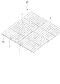
- FIG. It is a schematic explanatory drawing of the structure part SP which the self-propelled cleaning robot 1 of this embodiment cleans.
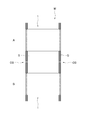
- FIG. in case the self-propelled cleaning robot 1 of this embodiment moves the module M.
- the self-propelled cleaning robot of the present invention is a robot for cleaning a planar portion in a structure, and can efficiently perform a cleaning operation even if a gap or a step is formed in the planar portion. It has the feature in doing so.
- the structure to be cleaned by the self-propelled cleaning robot of the present invention is a structure having a flat surface, and is not particularly limited as long as the self-propelled cleaning robot can move along the flat surface.
- a solar cell array of a large-scale solar power generation facility, a condensing mirror in a solar power generation facility, a solar water heater, and the like can be given.
- the plane to be cleaned can include the surface of the solar cell array (that is, the surface of the solar cell module), the surface of the condensing mirror (that is, the light receiving surface of the mirror), the light receiving surface of the solar water heater, and the like.
- the plane is a concept including a plane as a flat surface such as a solar cell array and a curved surface having a large curvature radius and almost flat like a collector mirror.
- the plurality of structures (modules) correspond to the above-described solar cell module and mirror, and the structure corresponds to a solar cell array and a collecting mirror.
- modules M a plurality of structures (modules) are referred to as modules M, and the structures are referred to as structures SP.
- the surface of the structural part SP to be cleaned (that is, each light receiving surface) is referred to as a target plane SF, and the surface of each module M is simply referred to as a surface S.
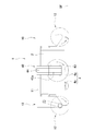
- the self-propelled cleaning robot 1 of this embodiment includes a robot body 2 having a moving unit 4 for traveling on a target plane SF of a structure SP, and the robot body 2. And a control unit that controls the movement of the moving means 4 and the pair of cleaning units 10 and 10.
- the robot body 2 includes a guide unit 40 that guides the movement of the robot body 2 when it moves on the target plane SF.
- the movement of the robot body 2 along the surface S of the module M, and when moving between the modules M, can be guided by the guide unit 40. I am doing so.
- the robot body 2 includes a moving means 4 for moving the self-propelled cleaning robot 1 along a target plane SF that is a target to be cleaned.
- the moving means 4 includes a pair of side drive wheels 4a and 4a and one intermediate drive wheel 4b. Specifically, the pair of side drive wheels 4a and 4a and the intermediate drive wheel 4b are arranged to form a triangle in plan view (see FIG. 1). For this reason, the self-propelled cleaning robot 1 can be stably arranged on the target plane SF.
- the pair of side drive wheels 4a and 4a employs general wheels that can only rotate around the rotation axis, but the intermediate drive wheel 4b employs omni wheels (omnidirectional wheels). Yes.
- all the driving wheels of the moving means 4 are connected to the driving motor 4m, respectively, so that each driving motor 4m can drive each driving wheel 4 independently.
- the operating states of all the drive motors 4m are controlled by a control unit provided in the robot body 2. For this reason, if the operation state of each drive motor is controlled by the control unit, the self-propelled cleaning robot 1 can be moved linearly or turned.
- the direction in which the side surface where the pair of side drive wheels 4 a and 4 a are not provided corresponds to the front-rear direction of the self-propelled cleaning robot 1.
- the intermediate drive wheel 4b side (lower side in FIG. 1) with respect to the pair of side drive wheels 4a and 4a is referred to as a rear part
- the opposite side (upper side in FIG. 1) is referred to as a front part.
- each drive motor is controlled by the control unit, and the movement of the self-propelled cleaning robot 1 is controlled.
- the movement path of the self-propelled cleaning robot 1 may be stored in the control unit and automatically moved on the target plane SF along the movement path. Further, the movement may be controlled by supplying a signal to the control unit from the outside. For example, the movement of the self-propelled cleaning robot 1 may be controlled by remote control using a remote controller or the like.
- the drive wheels 4 are not limited to the above-described configuration, and may be configured so that the self-propelled cleaning robot 1 can be moved linearly or turned.
- the omni wheel that is the intermediate drive wheel 4b may not be used as a drive wheel, but only a pair of drive wheels 4a and 4a may be used as drive wheels.
- a passive wheel may be employed for the intermediate drive wheel 4b.
- the moving direction of the self-propelled cleaning robot 1 can be freely changed by adjusting the rotational speeds of the pair of drive wheels 4a and 4a.
- the pair of cleaning parts 10 and 10 are provided at the front part and the rear part of the robot body part 2, respectively.
- each cleaning unit 10 is connected to the robot body 2 by a frame 11.
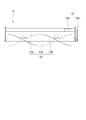
- the cleaning unit 10 includes a brush 12.
- the brush 12 includes a shaft portion 12 a and a pair of brush portions 12 b and 12 b provided on the outer peripheral surface of the shaft portion 12.
- Both ends of the shaft portion 12a are rotatably supported by the frame of the cleaning unit 10. Moreover, when the self-propelled cleaning robot 1 is placed on the target plane SF, the axial direction thereof is provided so as to be substantially parallel to the target plane SF.
- the pair of brush portions 12b and 12b are formed by arranging a plurality of brushes along the axial direction.
- Each brush portion 12b is provided such that the position of the brush is displaced along the circumferential direction as it moves in the axial direction of the shaft portion 12a (see FIGS. 1 and 4).
- each brush portion 12b is formed in a spiral shape on the side surface of the shaft portion 12a.
- the pair of brush portions 12b and 12b are arranged to form a double helix. That is, the pair of brush portions 12b and 12b are formed such that the brushes of the pair of brush portions 12b and 12b are rotated 180 degrees with respect to each other in the cross section orthogonal to the axial direction of the shaft portion 12a. (See FIG. 4).
- the cleaning part 10 is provided with the brush drive part 13 which rotates the axial part 12a of the brush 12 around an axis
- the brush drive unit 13 includes a brush drive motor 13a, and the main shaft of the brush drive motor 13a is connected to the end of the shaft 12a of the brush 12 by a belt pulley mechanism 13b.
- the operating state of the brush drive motor 13a is controlled by the control unit. For this reason, if the brush drive motor 13a is operated by the controller, the driving force is transmitted to the shaft 12a of the brush 12 via the belt pulley mechanism 13b, and the brush 12 can be rotated.
- the length of the brush which comprises a pair of brush parts 12b and 12b is not specifically limited, However, The front-end
- the length of the brush is preferably about 45 to 47 mm.
- this is determined in accordance with other parameters of the self-propelled cleaning robot 1, such as the rigidity of the brush, and needless to say, it is not limited to the above-mentioned dimensions.
- each brush part 12b does not need to arrange
- the brush may be arranged so as to be aligned along the axial direction of the shaft portion 12b, and is not particularly limited.
- the cleaning unit 10 cleans the target plane SF with the brush 12
- the method by which the cleaning unit 10 cleans the target plane SF is not particularly limited.
- the cleaning unit 10 is provided with a watering device (spray nozzle, etc.) and a wiper blade (squeegee) in addition to the brush 12, or a watering device (spray nozzle, etc.) and a wiper blade (squeegee) instead of the brush 12.
- a vacuum cleaner suction type vacuum cleaner
- only the vacuum cleaner suction type vacuum cleaner
- the guide unit 40 Next, the guide unit 40 will be described.
- the target plane SF side is referred to as the lower side
- the opposite side to the target plane SF is referred to as the upper side.
- the guide portion 40 is attached to the frame 11 via the base member 41.
- the base member 41 is provided with a turning guide 42 and a pair of groove movement guides 45 and 45.
- the turning guide portion 42 includes a fixed frame 42 a fixed to the base member 41, a shaft member 43, and an air cylinder 44.
- the fixed frame 42a is a hollow box-shaped member, and a through hole is formed in a lower end surface thereof.
- a shaft member 43 is provided in the fixed frame 42a.
- the shaft member 43 is disposed such that the tip thereof is positioned in the through hole on the lower end surface of the fixed frame 42a.
- the shaft member 43 is provided such that the axial direction thereof is substantially orthogonal to the lower end surface of the fixed frame 42a. That is, in the robot mounting state, the axial direction of the shaft member 43 is provided so as to be substantially orthogonal to the target plane SF.
- the shaft member 43 can move along the axial direction.
- an air cylinder 44 is provided on the fixed frame 42a.
- the air cylinder 44 is provided so that the axial direction thereof is substantially orthogonal to the target plane SF in the robot placement state.
- the air cylinder 44 is provided such that its axial direction is substantially parallel to the axial direction of the shaft member 43.
- the rod of the air cylinder 44 is connected to the base end portion of the shaft member 43. That is, the shaft member 43 can be moved in the axial direction by operating the rod of the air cylinder 44.
- the turning guide portion 42 causes the tip of the shaft member 43 to protrude from the lower end surface of the fixed frame 42a, or the tip of the shaft member 43 protrudes from the lower end surface of the fixed frame 42a. It is possible to change the length to be performed. That is, when the air cylinder 44 is operated, the turning guide part 42 can move the tip end of the shaft member 43 closer to and away from the target plane SF.
- the structure of the shaft member moving mechanism 44 is not particularly limited, and other than the mechanism using the cylinder described above, for example, a structure using a screw / nut mechanism or a structure using a rack / pinion mechanism may be adopted. it can.
- a pair of groove movement guides 45, 45 As shown in FIG. 3, a pair of groove movement guide portions 45, 45 are attached to the base member 41 so as to sandwich the turning guide portion 42 from the front-rear direction.
- the pair of groove movement guide portions 45, 45 have substantially the same structure, and are provided substantially symmetrically with respect to the turning guide portion 42. Therefore, in the following, the groove movement guide part 45 positioned forward (left side in FIG. 3) with respect to the turning guide part 42 will be described as a representative.
- a support bracket 45 a is erected on the base member 41 in front of the turning guide portion 42.
- a stopper plate 45b is provided above the support bracket 45a, and a pair of guide rails 45c and 45c are provided between the stopper plate 45b and the support bracket 45a along the vertical direction.
- the pair of guide rails 45c and 45c are arranged so that the axial direction thereof is substantially orthogonal to the target plane SF in the robot mounting state.
- the pair of guide rails 45c, 45c is provided with a vertically moving member 46 that is movable along the pair of guide rails 45c, 45c.
- an air cylinder 45d is attached to the lower surface of the support bracket 45a.
- the air cylinder 45d is disposed such that its rod faces upward and the tip of the rod projects upward from the upper surface of the support bracket 45a.
- the rod of the air cylinder 45d is connected to the vertical movement member 46. The reason why the air cylinder 45d is provided will be described later.
- a vertical movement member 46 of the groove movement guide portion 45 is provided in front of the base member 41. As described above, the vertical movement member 46 is provided so as to be movable along the pair of guide rails 45c and 45c.
- the vertical movement member 46 is provided with a pair of swing arms 47, 47.
- the upper ends of the pair of swing arms 47 and 47 are pivotally attached to the vertical movement member 46.
- the pair of swing arms 47, 47 are provided so as to be swingable within a plane (hereinafter simply referred to as an arm swing surface) perpendicular to the target plane SF and parallel to the front-rear direction in a state of being parallel to each other. It has been.
- the pair of swing arms 47 and 47 is maintained by a restoring means such as a spring so that the axial direction thereof is orthogonal to the target plane SF in the robot mounting state.
- a guide member 48 is provided at the lower ends of the pair of swing arms 47, 47 via a meandering detection unit 60.
- the guide member 48 is a plate-like member, and is provided so that the surface thereof is substantially parallel to the arm swinging surface.
- the guide member 48 is arranged so as to be aligned with the shaft member 43 of the turning guide portion 42 in the front-rear direction. For example, when a plane passing through the middle of the guide member 48 in the thickness direction and parallel to the arm swinging surface is defined, the shaft member 43 of the turning guide portion 42 is disposed in the plane.
- the shaft member 43 is provided so as to be sandwiched between the pair of guide members 48 and 48. Yes.
- the pair of swing arms 47 and 47 is pivoted by a restoring means such as a spring.
- the direction is maintained so as to be orthogonal to the target plane SF.
- the pair of swing arms 47 and 47 return to the original state (a state orthogonal to the target plane SF) by restoring means such as a spring. Rocks. Then, the guide member 48 returns to the state before the force is applied (position in the front-rear direction and height in the up-down direction).
- the groove movement guide 45 includes a mechanism for detecting the swing of the swing arms 47 and 47. Then, when it is detected that the swinging arms 47, 47 of the groove movement guide unit 45 positioned forward with respect to the shaft member 43 of the turning guide unit 42 have exceeded a predetermined amount, the air cylinder 44 is contracted. It is configured as follows. For example, a sensor detects the swing of the swing arms 47 and 47 of the groove movement guide 45 positioned forward with respect to the shaft member 43 of the turning guide 42, and the air cylinder 44 contracts in response to a signal from the sensor. It is possible to adopt a configuration that operates as described above.
- the air cylinder 44 is extended. It is configured to let you.
- the sensor detects the swing of the swing arms 47 and 47 of the groove movement guide portion 45 located rearward with respect to the shaft member 43 of the turning guide portion 42, and the air cylinder 44 is extended by a signal from the sensor. It is possible to adopt a configuration that is actuated automatically.
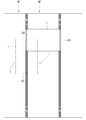
- a gap G is formed between the long sides of the module M, and a member (obstacle OB) that connects adjacent solar cell modules is located in the gap G.
- the width of the self-propelled cleaning robot 1 in other words, the width of the brush 12 is substantially the same as the width of the module M, and along the longitudinal direction of the module M (vertical direction in FIG. 7). A case where the self-propelled cleaning robot 1 moves to clean the surface S of the module M will be described.
- the self-propelled cleaning robot 1 is caused to travel by the moving means 4 while rotating the brush 12 of the cleaning unit 10. Then, since the shaft member 43 and the pair of guide members 48 and 48 move along the groove G, the self-propelled cleaning robot 1 can be moved along the longitudinal direction of the module M.
- the self-propelled cleaning robot 1 will be moved along the longitudinal direction of the module M once. Only the entire width of the surface S of the module M can be cleaned.
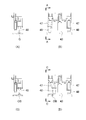
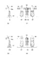
- the self-propelled cleaning robot 1 does not move while the tip of the shaft member 43 of the guide portion 40 and the tip of the pair of guide members 48 and 48 are inserted into the groove G. It moves along G (FIGS. 8A and 8B).
- a guide member 48 (hereinafter, referred to as the front guide member 48) positioned forward in the traveling direction with respect to the shaft member 43 comes into contact with the obstacle OB. Then, a force corresponding to the moving speed of the self-propelled cleaning robot 1 is applied to the front guide member 48 from the obstacle OB.
- the front guide member 48 is supported by the pair of swing arms 47 and 47 so as to be swingable in the front-rear direction, even if it touches the obstacle OB, it is in a direction opposite to the traveling direction of the self-propelled cleaning robot 1. Move and move upward.
- the swing arms 47 and 47 swing greatly, and eventually the front guide member 48 The lower end moves to the vicinity of the upper end of the obstacle OB.
- the air cylinder 44 is contracted, so that the tip of the shaft member 43 is moved away from the target plane SF. Specifically, it moves until it is located above the upper end of the obstacle OB (FIGS. 8C and 8D).
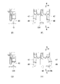
- the shaft member 43 passes through the position of the obstacle OB. At this time, the shaft member 43 passes over the obstacle OB. At this time, since the tip of the shaft member 43 is maintained in a state of being moved until it is positioned above the upper end of the obstacle OB, the shaft member 43 does not become an obstacle to the movement of the self-propelled cleaning robot 1 ( FIG. 9 (E), (F)).
- the guide member 48 hereinafter referred to as the rear guide member 48
- the self-propelled cleaning robot 1 moves along the groove G. Move stably.
- the front guide member 48 gets over the obstacle OB, the pair of swing arms 47, 47 to which the front guide member 48 is attached is restored to the original state, and the front end of the front guide member 48 is It is inserted into the groove G again. That is, substantially, when the shaft member 43 passes over the obstacle OB, the front guide member 48 is also inserted into the groove G, and the pair of guide members 48 and 48 are inserted into the groove G. It becomes a state.
- the rear guide member 48 contacts the obstacle OB. Then, similarly to the front guide member 48, the rear guide member 48 moves in the direction opposite to the traveling direction of the self-propelled cleaning robot 1 and also moves upward. When this swinging is detected by a sensor or the like, the air cylinder 44 is extended, so that the tip of the shaft member 43 is inserted into the groove G again (FIGS. 9G and 9H).
- the self-propelled cleaning robot 1 can be moved along the groove G in a stable state, and even if there is an obstacle OB in the groove G, self-propelled The movement of the type cleaning robot 1 along the groove G can be continued.
- the pair of swinging arms 47, 47 described above corresponds to a guide member moving mechanism referred to in the claims.
- the self-propelled cleaning robot 1 has been described with respect to the case where the tips of the pair of guide members 48 and 48 are both disposed in the groove G except when the obstacle OB is exceeded.
- the tip of one of the pair of guide members 48, 48 may be disposed in the groove G.
- the tip of the front guide member 48 is disposed in the groove G, but the tip of the rear guide member 48 is detached from the groove G.
- the front air cylinder 45d (hereinafter referred to as the front air cylinder 45d) is contracted and the front guide member 48 is lowered downward together with the vertical movement member 46, while the rear air cylinder 45d ( Hereinafter, the rear air cylinder 45d) is extended so that the rear guide member 48 is pushed upward together with the up-and-down moving member 46.
- the sensor detects the swing, the front air cylinder 45d extends, and the front guide member 48 is above the obstacle OB.
- the rear air cylinder 45d contracts so that the rear guide member 48 is lowered to the position where the tip is inserted into the groove G.
- the front air cylinder 45d is contracted so that the front guide member 48 is lowered to the position where the tip is inserted into the groove G.
- the pair of guide members 48, 48 are operated as described above, the pair of guide members 48, 48 are compared with the case where both ends of the pair of guide members 48, 48 are inserted into the groove G. Since the possibility of contact with the module M can be reduced, there is a possibility that the traveling of the self-propelled cleaning robot 1 can be made smooth.
- the fixed frame 42 a that holds the shaft member 43 is fixed to the base member 41 and the pair of guide members 48 and 48 are swung by the pair of swing arms 47 and 47 has been described.
- the fixed frame 42 a that holds the shaft member 43 may swing with respect to the base member 41.
- the shaft member 43 can be operated substantially in the same manner as the pair of guide members 48 and 48.
- the operation in the case of such a configuration will be described.
- the front air cylinder 45d is contracted, the tip of the front guide member 48 is disposed in the groove G, and the air cylinder 44 And the tip of the shaft member 43 is also disposed in the groove G.
- the rear air cylinder 45d extends and the tip of the rear guide member 48 is detached from the groove G.
- the shaft member 43 eventually comes into contact with the obstacle OB. Then, when the shaft member 43 (that is, the fixed frame 42a) swings and swings by a predetermined angle, the sensor detects the swing and the air cylinder 44 contracts, so that the shaft member 43 is above the obstacle OB. Move up. At this time, the front air cylinder 45d contracts, and the front guide member 48 is lowered to a position where the tip is inserted into the groove G. On the other hand, the rear guide member 48 is maintained in a state where the tip is inserted into the groove G. That is, the pair of guide members 48 are inserted into the groove G.
- the shaft member 43 eventually passes over the obstacle OB, the rear guide member 48 comes into contact with the obstacle OB, and the rear guide member 48 swings.
- the sensor detects the swing, the rear air cylinder 45d extends, and the rear guide member 48 moves above the obstacle OB.
- the air cylinder 44 extends, and the shaft member 43 protrudes to a position where the tip is inserted into the groove G.
- the front guide member 48 is maintained in a state where the front end is inserted into the groove G, so that the front guide member 48 and the shaft member 43 are inserted into the groove G. That is, the self-propelled cleaning robot 1 returns to a state where it is traveling in a portion where there is no obstacle OB.
- the self-propelled cleaning robot 1 can continue to move along the groove G of the self-propelled cleaning robot 1 even if the obstacle OB exists in the groove G. Moreover, since two members (that is, the pair of guide members 48 or the shaft member 43 and one guide member 48) are always inserted into the groove G, the self-propelled cleaning robot 1 can be stabilized. Thus, it can be moved along the groove G.
- the self-propelled cleaning robot 1 stops moving along the groove G. Subsequently, only the guide members 48 and 48 of the pair of groove movement guide portions 45 and 45 of the guide portion 40 are detached from the groove G while the shaft member 43 of the turning guide portion 42 is inserted into the groove G. Specifically, the vertical movement member 46 is raised by the air cylinder 45d, and the guide members 48, 48 are raised together with the pair of swing arms 47, 47.
- the drive motor 4m is operated by the movement control unit 31 of the self-propelled cleaning robot 1 so that the robot body 2 moves around the axis of the shaft member 43. Then, the self-propelled cleaning robot 1 turns around the shaft member 43.
- the self-propelled cleaning robot 1 can be moved to the adjacent module M.
- the shaft member 43 is inserted in the groove G, the arrangement of the self-propelled cleaning robot 1 and the module M can be changed to the front and rear of the original module M if the same module M is arranged side by side.
- the relative positional relationship of the module M in the width direction can be made substantially the same. That is, when there is a gap G between the modules M, even if the self-propelled cleaning robot 1 moves between the modules M, the relative positional relationship between the self-propelled cleaning robot 1 and the module M is substantially the same. Can be in a state.
- any module M can be cleaned in the same state.
- the positioning can be performed only by turning the self-propelled cleaning robot 1 around the shaft member 43, the positioning of the self-propelled cleaning robot 1 is facilitated, so that the work efficiency can be improved.
- the self-propelled cleaning robot 1 sandwiches the robot body 2 from the pair of drive wheels 4a and 4a in the axial direction (that is, the direction parallel to the axial direction of the shaft 12b of the brush 12). 40 may be provided.
- the distance between the shaft members 43 of the pair of guide portions 40 and 40 and the distance between the corresponding guide members 48 are set to the distance between adjacent grooves G (that is, approximately the same length as the width of the module M). deep. Then, since the module M to be cleaned is substantially sandwiched from the width direction and moved along its long side, the self-propelled cleaning robot 1 is more reliably moved along the longitudinal direction of the module M. Can be made.
- the shaft member 43 of the guide portion 42 is provided on both sides of the self-propelled cleaning robot 1.
- the degree of freedom of posture when moving from module M to another module M can be increased.
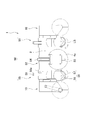
- the front-rear direction of the self-propelled cleaning robot 1 is reversed. If it exists, by rotating the self-propelled cleaning robot 1 as shown in FIG. 10, the front-rear direction of the self-propelled cleaning robot 1 after the movement can be made the same direction as before the movement.
- the shaft member 43 (one shaft member 43, 43) of the left guide portion 40 of the self-propelled cleaning robot 1 is inserted into the groove G, and the self-propelled cleaning robot 1 turns 90 degrees clockwise.
- the shaft member 43 (the other shaft member 43) of the guide portion 40 located on the right side is inserted into the groove G, and the one shaft member 43 is detached from the groove G.
- the self-propelled cleaning robot 1 is turned 90 degrees counterclockwise around the other shaft member 43.
- the direction of the front-rear direction of the self-propelled cleaning robot 1 after the movement can be set to the same direction as before the movement.
- the self-propelled cleaning robot 1 can be moved from one module M to another module M as in the case where the pair of guide parts 40 are provided.
- the self-propelled cleaning robot 1 can be moved along the longitudinal direction of the module M.
- the meandering detector 60 between the pair of swing arms 47 and 47 and the guide member 48 as described above.
- the meandering detection unit 60 detects a force applied to the guide member 48 from the width direction of the groove G and transmits the detected force to the movement control unit 31.
- the movement control unit 31 controls the operation of the drive motor 4m so as to correct the meandering. can do. Then, since the movement resistance of the self-propelled cleaning robot 1 can be reduced, the movement of the module M in the longitudinal direction can be stably continued.
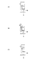
- the self-propelled cleaning robot 1 moves in the traveling direction as shown in FIG.
- a force is applied to the guide member 48 positioned forward so as to be pushed inward from the outside.
- the operation of the drive motor 4m is controlled by the movement control unit 31 so that the self-propelled cleaning robot 1 turns left.
- the movement control unit 31 controls the operation of the drive motor 4m so that the self-propelled cleaning robot 1 goes straight. Then, the meandering of the self-propelled cleaning robot 1 is corrected.
- FIG. 14 shows that only one turning guide part 42 is provided in one guide part 40, the self-propelled cleaning robot 1 moves in the traveling direction as shown in FIG.
- a structure is provided in which a link mechanism that enables the guide member 48 to swing in the width direction of the groove G with respect to the pair of swinging arms 47 and 47 and a sensor that detects the amount of swinging are employed. It is preferable to do. In this case, when the guide member 48 comes into contact with the module M, the force generated by the contact can be released by the link mechanism.
- the meandering correction of the self-propelled cleaning robot 1 when such a link mechanism is provided will be described.
- the guide member 48 moves with an appropriate gap between the module M (FIG. 15 ( A)).
- the link mechanism since the link mechanism does not operate, the signal from the sensor is not transmitted to the movement control unit 31, and thus the operation of the drive motor 4m is maintained as it is. That is, the movement control unit 31 controls the operation of the drive motor 4m so that the self-propelled cleaning robot 1 moves straight, and the self-propelled cleaning robot 1 is maintained in a state of moving along the axial direction of the groove G.
- the movement control unit 31 controls the operation of the drive motor 4m so that the self-propelled cleaning robot 1 moves straight, and the self-propelled cleaning robot 1 is maintained in a state of moving along the axial direction of the groove G.
- the movement control unit 31 controls the operation of the drive motor 4m so that the self-propelled cleaning robot 1 goes straight, and the self-propelled cleaning robot 1 returns to the state of moving along the axial direction of the groove G.
- the link mechanism operates so as to release the force.
- the sensor detects that the link mechanism is activated, a signal from the sensor is transmitted to the movement control unit 31, and the movement control unit 31 controls the operation of the drive motor 4m so as to correct the meandering. Then, since the force applied to the guide member 48 is removed, the link mechanism operates to return to the original state.
- the movement control unit 31 controls the operation of the drive motor 4m so that the self-propelled cleaning robot 1 goes straight, and the self-propelled cleaning robot 1 returns to the state of moving along the axial direction of the groove G.
- the structure of the meandering detection unit 60 is not limited to the structure having the link mechanism described above, and various structures can be adopted.
- a contact sensor, a pressure sensor, a distance sensor, or the like may be provided on the surface of the guide member 48 to measure the force directly applied to the guide member 48 or the degree of meandering.
- the guide unit 40 described above has been described with respect to the case where the pair of groove movement guide units 45, 45 inserts the plate-shaped guide member 48 into the groove G, and the case where the guide member 48 is swung away from the groove G. .
- the obstacle OB can be passed while continuing the movement of the self-propelled cleaning robot 1 while following the groove G.
- the portion where the self-propelled cleaning robot 1 contacts the surface S of the module M is only three drive wheels 4 except for the brush 12.
- the self-propelled cleaning robot 1 since the self-propelled cleaning robot 1 receives the reaction force from the surface S of the module M only by the three driving wheels 4, the friction between the driving wheels 4 and the surface S of the module M can be increased. Therefore, it is possible to obtain an advantage that the drive wheels 4 are less likely to slip when the self-propelled cleaning robot 1 travels. Then, even if the inclination of the surface S of the module M becomes large (for example, about 15 ° to 20 °), the self-propelled cleaning robot 1 can be moved along the surface S of the module M.
- the following structure can also be adopted as the pair of groove movement guide portions 45, 45.
- the guide unit 50 when the other groove movement guide unit 55 is employed will be described.
- portions of the guide portion 50 having a structure substantially equivalent to that of the guide portion 40 will not be described as appropriate.
- a turning guide portion 52 having substantially the same structure as the turning guide portion 42 described above is attached to the frame 11.
- a pair of groove movement guide portions 55, 55 are attached to the frame 11 so as to sandwich the turning guide portion 52 from the front-rear direction.
- the groove movement guide part 55 is provided with the air cylinder 59, and has the function which raises the wheel block 56, when turning the self-propelled cleaning robot 1 similarly to the groove movement guide part 45. .
- the pair of groove movement guide portions 55 and 55 have substantially the same structure, and are provided substantially symmetrically with respect to the turning guide portion 52. Therefore, in the following, the groove movement guide part 55 located in front of the turning guide part 52 (left side in FIG. 11) will be described as a representative.
- the groove movement guide portion 55 includes a fixed frame 55 a fixed to the frame 11, a wheel block 56, and a bias that biases the wheel block 56 downward (that is, toward the target plane SF). Means.
- the fixed frame 55a is a hollow box-shaped member having an opening on the front surface and the bottom surface.
- the wheel block 56 is disposed inside the fixed frame 55a.
- the wheel block 56 includes a stepped wheel 57 and a cover 58 that accommodates the stepped wheel 57.
- the stepped wheel 57 includes a guide wheel portion 57a having a large diameter and a pair of traveling wheel portions 57b and 57b positioned on both sides of the guide wheel portion 57a in the rotation axis direction.
- the rotational axis direction of the stepped wheel 57 is provided so as to be parallel to the axial direction of the drive wheel 4. Further, the width of the guide wheel portion 57a of the stepped wheel 57 is formed to be narrower than the width of the groove G, and the width including the pair of traveling wheel portions 57b and 57b is larger than the width of the groove G. It is formed to be wide.
- the fixed frame 55a is provided with an urging means.
- the biasing means is, for example, a spring or the like, and when the wheel block 56 is biased downward (that is, toward the target plane SF) and a force that pushes the wheel block 56 upward against the stepped wheel 57 is applied, The wheel block 56 is held so that it can move upward according to the force.
- the urging means is provided so that the wheel block 56, that is, the stepped wheel 57 can be moved up and down along a direction substantially orthogonal to the target plane SF in the robot placement state.
- the groove movement guide portion 55 can move the stepped wheel 57 closer to and away from the target plane SF if a force is applied to the stepped wheel 57 from a direction substantially orthogonal to the target plane SF.
- the stepped wheel 57 corresponds to a guide member referred to in the claims
- the biasing means corresponds to a guide member moving mechanism referred to in the claims.
- the structure of the guide member moving mechanism is not particularly limited as long as it exhibits the functions described above, and a spring, an air damper, or the like can be employed.
- the groove movement guide unit 55 includes a mechanism for detecting the movement amount of the stepped wheel 57. Then, when it is detected that the stepped wheel 57 of the groove movement guide part 55 positioned forward with respect to the shaft member 43 of the turning guide part 42 moves upward by a predetermined amount or more and then returns to the original state, the turning guide part When the air cylinder 54 of 52 is contracted and, conversely, it is detected that the stepped wheel 57 of the groove movement guide portion 55 located rearward with respect to the shaft member 53 of the turning guide portion 52 has moved upward by a predetermined amount or more.
- the air cylinder 54 of the guide 52 is configured to extend.
- the self-propelled cleaning robot 1 is caused to travel by the moving means 4 while rotating the brush 12 of the cleaning unit 10. Then, the shaft member 43 moves following the groove G, and the stepped wheel 57 rolls in a state where the guide wheel portion 57a is inserted into the groove G. Therefore, along the longitudinal direction of the module M, the self-propelled type The cleaning robot 1 can be moved.
- the self-propelled cleaning robot 1 does not move while the tip of the shaft member 43 of the guide portion 50 and the guide wheel portion 57a of the stepped wheel 57 are inserted into the groove G. It moves along G (FIGS. 12A and 12B).
- the stepped wheel 57 positioned forward in the traveling direction with respect to the shaft member 53 comes into contact with the obstacle OB. Then, since the force corresponding to the moving speed of the self-propelled cleaning robot 1 is applied to the stepped wheel 57 from the obstacle OB, the stepped wheel 57 of the groove movement guide portion 55 positioned forward in the traveling direction is moved upward. Move to. In other words, the stepped wheel 57 rides on the obstacle OB (FIGS. 12C and 12D).
- the stepped wheel 57 gets over the obstacle OB, and the guide wheel portion 57a of the stepped wheel 57 again enters the groove G. It will be inserted. Then, the air cylinder 54 of the turning guide 52 is contracted, and the tip of the shaft member 53 moves until it is positioned above the upper end of the obstacle OB. In this state, since the obstacle OB has not reached the position of the shaft member 53, the shaft member 53 does not interfere with the obstacle OB until the tip of the shaft member 53 moves upward.
- the shaft member 53 passes through the position of the obstacle OB. At this time, since the tip of the shaft member 53 is maintained in a state of being moved until it is located above the upper end of the obstacle OB, the shaft member 53 does not become an obstacle to the movement of the self-propelled cleaning robot 1 ( FIG. 13 (E), (F)). In addition, since the guide wheel portion 57a of the stepped wheel 57 of the two groove movement guide mechanism portions 55 positioned before and after the shaft member 53 is inserted into the groove G, the shaft member 53 is detached from the groove G. However, the self-propelled cleaning robot 1 moves along the groove G stably.
- the stepped wheel 57 positioned rearward in the traveling direction with respect to the shaft member 53 comes into contact with the obstacle OB, so that the groove movement guide positioned forward in the traveling direction.
- the stepped wheel 57 of the part 55 moves upward.
- the stepped wheel 57 rides on the obstacle OB (FIGS. 13G and 13H).
- the guide wheel portion 57a of the stepped wheel 57 is inserted into the groove G. It returns to the state before passing through the obstacle OB.
- the self-propelled cleaning robot 1 can be moved along the groove G in a stable state, and even if there is an obstacle OB in the groove G, self-propelled The movement of the type cleaning robot 1 along the groove G can be continued.
- the guide unit 50 may be provided with a level sensor LS that sets a reference for the target plane SF of the self-propelled cleaning robot 1.
- the level sensor LS is a member having a flat bottom surface and is urged downward by a cylinder or the like. That is, when the self-propelled cleaning robot 1 is placed on the target plane SF, the lower surface of the level sensor LS is provided in surface contact with the target plane SF.
- the following advantages can be obtained.
- the self-propelled cleaning robot 1 In a state where the self-propelled cleaning robot 1 is moving along the light receiving surface (that is, the target plane SF) of the solar cell module, either one of the pair of side drive wheels 4a and 4a of the self-propelled cleaning robot 1 When the side drive wheels 4a are positioned on the frame of the solar cell module, the posture of the robot body 2 is inclined forward or backward.
- the robot body 2 rarely swings in the front-rear direction as the brush 12 rotates.
- the robot main body 2 When the robot main body 2 is tilted in the front-rear direction as described above, one of the front and rear of the robot main body 2 may be in a floating state and the other may be in a depressed state. Then, the stepped wheel 57 attached to the floating side floats from the groove G. On the other hand, the stepped wheel 57 attached to the sinking side is that the stepped wheel 57 is pushed up in a direction away from the traveling surface (target plane SF) (that is, the reaction wheel receives a reaction force from the frame). There is a possibility that malfunction is caused by judging that the groove G has a failure OB.
- target plane SF traveling surface
- the level sensor LS as described above is provided, the distance in the direction away from the target plane SF can be detected not using the position of the robot body 2 as a reference but using the position of the target plane SF as a reference. Therefore, it is possible to stably detect whether there is a failure OB in the groove G regardless of the change in the posture of the robot body 2.
- the self-propelled cleaning robot of the present invention is suitable as a robot for cleaning a solar cell array of a large-scale solar power generation facility, a condensing mirror of a large-scale solar power generation facility, a light receiving surface in a solar water heater, and the like.
Landscapes
- Engineering & Computer Science (AREA)
- Architecture (AREA)
- Chemical & Material Sciences (AREA)
- Mechanical Engineering (AREA)
- Physics & Mathematics (AREA)
- Electrochemistry (AREA)
- Chemical Kinetics & Catalysis (AREA)
- Civil Engineering (AREA)
- Structural Engineering (AREA)
- Thermal Sciences (AREA)
- Combustion & Propulsion (AREA)
- Sustainable Energy (AREA)
- General Engineering & Computer Science (AREA)
- Sustainable Development (AREA)
- Life Sciences & Earth Sciences (AREA)
- Electric Vacuum Cleaner (AREA)
- Manipulator (AREA)
- Evolutionary Computation (AREA)
- Game Theory and Decision Science (AREA)
- Cleaning In General (AREA)
- Cleaning By Liquid Or Steam (AREA)
- Photovoltaic Devices (AREA)
- Business, Economics & Management (AREA)
- Control Of Position, Course, Altitude, Or Attitude Of Moving Bodies (AREA)
- Health & Medical Sciences (AREA)
- Automation & Control Theory (AREA)
- Artificial Intelligence (AREA)
- Medical Informatics (AREA)
- Aviation & Aerospace Engineering (AREA)
- Radar, Positioning & Navigation (AREA)
- Remote Sensing (AREA)
- General Physics & Mathematics (AREA)
- Nozzles For Electric Vacuum Cleaners (AREA)
Priority Applications (6)
| Application Number | Priority Date | Filing Date | Title |
|---|---|---|---|
| US14/430,717 US10020774B2 (en) | 2012-12-25 | 2013-12-25 | Self-propelled cleaning robot |
| JP2014521772A JP5686272B2 (ja) | 2012-12-25 | 2013-12-25 | 自走式掃除ロボット |
| IN2485DEN2015 IN2015DN02485A (enExample) | 2012-12-25 | 2013-12-25 | |
| EP13867860.2A EP2898961B1 (en) | 2012-12-25 | 2013-12-25 | Self-propelled cleaning robot |
| IL239620A IL239620B (en) | 2012-12-25 | 2015-06-24 | Self-propelled cleaning robot |
| SA515360677A SA515360677B1 (ar) | 2012-12-25 | 2015-06-25 | إنسان آلي ذاتي الدفع للتنظيف |
Applications Claiming Priority (2)
| Application Number | Priority Date | Filing Date | Title |
|---|---|---|---|
| JP2012-281531 | 2012-12-25 | ||
| JP2012281531 | 2012-12-25 |
Publications (1)
| Publication Number | Publication Date |
|---|---|
| WO2014103291A1 true WO2014103291A1 (ja) | 2014-07-03 |
Family
ID=51020409
Family Applications (1)
| Application Number | Title | Priority Date | Filing Date |
|---|---|---|---|
| PCT/JP2013/007561 Ceased WO2014103291A1 (ja) | 2012-12-25 | 2013-12-25 | 自走式掃除ロボット |
Country Status (7)
| Country | Link |
|---|---|
| US (1) | US10020774B2 (enExample) |
| EP (1) | EP2898961B1 (enExample) |
| JP (1) | JP5686272B2 (enExample) |
| IL (1) | IL239620B (enExample) |
| IN (1) | IN2015DN02485A (enExample) |
| SA (1) | SA515360677B1 (enExample) |
| WO (1) | WO2014103291A1 (enExample) |
Cited By (5)
| Publication number | Priority date | Publication date | Assignee | Title |
|---|---|---|---|---|
| WO2016098140A1 (ja) * | 2014-12-17 | 2016-06-23 | 株式会社 スカイロボット | 太陽光発電パネルの洗浄装置 |
| CN109074071A (zh) * | 2016-03-31 | 2018-12-21 | 株式会社未来机械 | 作业机器人以及边缘检测器 |
| CN110881914A (zh) * | 2019-12-11 | 2020-03-17 | 苏州康鸿智能装备股份有限公司 | 一种具有双刮刀机构的幕墙机器人 |
| CN112254657A (zh) * | 2020-09-21 | 2021-01-22 | 河南颂达信息技术有限公司 | 一种基于视觉感知的智能清雪机器人调度方法 |
| JP2022161334A (ja) * | 2021-04-08 | 2022-10-21 | 株式会社Ssg | ソーラーパネル洗浄装置及びソーラーパネルの洗浄方法 |
Families Citing this family (29)
| Publication number | Priority date | Publication date | Assignee | Title |
|---|---|---|---|---|
| JP5686271B2 (ja) * | 2012-12-25 | 2015-03-18 | 株式会社未来機械 | 自走式掃除ロボット |
| JP6475246B2 (ja) | 2013-09-05 | 2019-02-27 | アリオン エナジー,インコーポレーテッド | 太陽光発電モジュールのレールベースアレイを保守するためのシステム、輸送手段、及び方法 |
| US9453660B2 (en) | 2013-09-11 | 2016-09-27 | Alion Energy, Inc. | Vehicles and methods for magnetically managing legs of rail-based photovoltaic modules during installation |
| WO2017022264A1 (ja) * | 2015-08-04 | 2017-02-09 | シャープ株式会社 | 清掃装置 |
| WO2017044566A1 (en) | 2015-09-11 | 2017-03-16 | Alion Energy, Inc. | Wind screens for photovoltaic arrays and methods thereof |
| TWI681748B (zh) * | 2016-01-28 | 2020-01-11 | 原相科技股份有限公司 | 自動清掃機控制方法以及自動清掃機 |
| CN105680787B (zh) * | 2016-03-02 | 2018-05-04 | 杭州舜海光伏科技有限公司 | 光伏电池板清扫设备的刮刀机构 |
| CN107198499B (zh) * | 2016-03-18 | 2021-03-05 | 松下电器(美国)知识产权公司 | 自主移动装置、自主移动方法以及自主移动系统 |
| WO2018009650A1 (en) * | 2016-07-08 | 2018-01-11 | Alion Energy, Inc. | Systems, methods, and vehicles for maintaining solar panels |
| MX2019000052A (es) * | 2016-07-08 | 2019-05-02 | Alion Energy Inc | Sistemas, métodos y vehículos para mantener los paneles solares. |
| CN106227215A (zh) * | 2016-08-31 | 2016-12-14 | 宁波易拓智谱机器人有限公司 | 机器人自动光伏组件清洗系统及其清洗方法 |
| CN106354134B (zh) * | 2016-09-12 | 2020-10-02 | 深圳创动科技有限公司 | 一种太阳能电池板的维护管理系统及其维护管理方法 |
| US10498288B2 (en) | 2017-01-26 | 2019-12-03 | Evermore United S.A. | Waterless cleaning system and method for solar trackers using an autonomous robot |
| US11201583B2 (en) | 2017-01-26 | 2021-12-14 | Evermore United S.A. | Waterless cleaning system and method for solar trackers using an autonomous robot |
| US10498287B2 (en) | 2017-01-26 | 2019-12-03 | Evermore United S.A. | Waterless cleaning system and method for solar trackers using an autonomous robot |
| US10797636B2 (en) | 2017-01-26 | 2020-10-06 | Evermore United S.A. | Waterless cleaning system and method for solar trackers using an autonomous robot |
| CN106733860A (zh) * | 2017-02-17 | 2017-05-31 | 西部国际绿色能源斯特林(贵州)智能装备制造有限公司 | 一种轨道式机器人碟面清洗装置 |
| US11357512B2 (en) | 2017-05-12 | 2022-06-14 | Robert Fishel | Mechanism and device for left atrial appendage occlusion with electrical isolation |
| US12408924B2 (en) | 2017-05-12 | 2025-09-09 | Robert S. Fishel | Mechanism and device for left atrial appendage occlusion with electrical isolation |
| CN108284089B (zh) * | 2018-03-30 | 2023-10-03 | 河北建筑工程学院 | 太阳能板材清洁机器人 |
| CN108634873A (zh) * | 2018-04-10 | 2018-10-12 | 佛山市人和科技有限公司 | 一种经济环保的生活清洗装置 |
| CN109465212B (zh) * | 2018-09-30 | 2021-12-03 | 台州市路桥友顺纸塑包装材料厂 | 一种电热水器顶部定期擦洗方法 |
| CN109442741A (zh) * | 2018-09-30 | 2019-03-08 | 刘宝玉 | 具有顶部定期擦洗功能的电热水器 |
| US10873291B1 (en) * | 2018-11-06 | 2020-12-22 | Mary Ethel Parker | Methods for cleaning photovoltaic panels |
| DE202019101423U1 (de) * | 2019-03-13 | 2020-06-16 | Franz Ehleuter | Vorrichtung zur Behandlung glatter Flächen, insbesondere der Oberfläche von Photovoltaik- und Solaranlagen |
| CN109730594A (zh) * | 2019-03-27 | 2019-05-10 | 南京英维尔科技服务有限公司 | 一种扫地机器人 |
| CN113193829A (zh) * | 2021-05-28 | 2021-07-30 | 常州机电职业技术学院 | 一种太阳能板清洗装置 |
| CN117282698B (zh) * | 2023-09-20 | 2024-08-13 | 宁夏隆基宁光仪表股份有限公司 | 一种光伏清洁机器人及其自主选择清洁路线的方法 |
| FR3166080A1 (fr) * | 2024-09-11 | 2026-03-13 | Leon | Robot de nettoyage de pergolas a lames |
Citations (5)
| Publication number | Priority date | Publication date | Assignee | Title |
|---|---|---|---|---|
| JPH10202563A (ja) * | 1997-01-17 | 1998-08-04 | Mitsui Eng & Shipbuild Co Ltd | 壁面清掃装置 |
| JP2002273351A (ja) * | 2001-03-19 | 2002-09-24 | Hino Jushi:Kk | 太陽電池パネル外装面クリ−ニング方法及び装置 |
| JP2004166968A (ja) | 2002-11-20 | 2004-06-17 | Zojirushi Corp | 自走式掃除ロボット |
| JP2004186632A (ja) * | 2002-12-06 | 2004-07-02 | Yanmar Agricult Equip Co Ltd | 太陽電池パネル装置 |
| JP4808803B2 (ja) * | 2009-08-18 | 2011-11-02 | 株式会社旭メカニカル | 太陽電池パネル洗浄装置 |
Family Cites Families (3)
| Publication number | Priority date | Publication date | Assignee | Title |
|---|---|---|---|---|
| JPS5787562A (en) * | 1980-11-20 | 1982-06-01 | Mitsubishi Electric Corp | Automatic cleaning device |
| KR101024983B1 (ko) * | 2009-02-09 | 2011-03-25 | 송원진 | 솔라 패널의 클리닝 장치 |
| US9480379B2 (en) * | 2011-10-21 | 2016-11-01 | Samsung Electronics Co., Ltd. | Robot cleaner and control method for the same |
-
2013
- 2013-12-25 US US14/430,717 patent/US10020774B2/en not_active Expired - Fee Related
- 2013-12-25 WO PCT/JP2013/007561 patent/WO2014103291A1/ja not_active Ceased
- 2013-12-25 IN IN2485DEN2015 patent/IN2015DN02485A/en unknown
- 2013-12-25 EP EP13867860.2A patent/EP2898961B1/en not_active Not-in-force
- 2013-12-25 JP JP2014521772A patent/JP5686272B2/ja not_active Expired - Fee Related
-
2015
- 2015-06-24 IL IL239620A patent/IL239620B/en active IP Right Grant
- 2015-06-25 SA SA515360677A patent/SA515360677B1/ar unknown
Patent Citations (5)
| Publication number | Priority date | Publication date | Assignee | Title |
|---|---|---|---|---|
| JPH10202563A (ja) * | 1997-01-17 | 1998-08-04 | Mitsui Eng & Shipbuild Co Ltd | 壁面清掃装置 |
| JP2002273351A (ja) * | 2001-03-19 | 2002-09-24 | Hino Jushi:Kk | 太陽電池パネル外装面クリ−ニング方法及び装置 |
| JP2004166968A (ja) | 2002-11-20 | 2004-06-17 | Zojirushi Corp | 自走式掃除ロボット |
| JP2004186632A (ja) * | 2002-12-06 | 2004-07-02 | Yanmar Agricult Equip Co Ltd | 太陽電池パネル装置 |
| JP4808803B2 (ja) * | 2009-08-18 | 2011-11-02 | 株式会社旭メカニカル | 太陽電池パネル洗浄装置 |
Non-Patent Citations (1)
| Title |
|---|
| See also references of EP2898961A4 |
Cited By (7)
| Publication number | Priority date | Publication date | Assignee | Title |
|---|---|---|---|---|
| WO2016098140A1 (ja) * | 2014-12-17 | 2016-06-23 | 株式会社 スカイロボット | 太陽光発電パネルの洗浄装置 |
| JPWO2016098140A1 (ja) * | 2014-12-17 | 2017-04-27 | 株式会社 スカイロボット | 太陽光発電パネルの洗浄装置 |
| CN109074071A (zh) * | 2016-03-31 | 2018-12-21 | 株式会社未来机械 | 作业机器人以及边缘检测器 |
| CN110881914A (zh) * | 2019-12-11 | 2020-03-17 | 苏州康鸿智能装备股份有限公司 | 一种具有双刮刀机构的幕墙机器人 |
| CN112254657A (zh) * | 2020-09-21 | 2021-01-22 | 河南颂达信息技术有限公司 | 一种基于视觉感知的智能清雪机器人调度方法 |
| JP2022161334A (ja) * | 2021-04-08 | 2022-10-21 | 株式会社Ssg | ソーラーパネル洗浄装置及びソーラーパネルの洗浄方法 |
| JP7650059B2 (ja) | 2021-04-08 | 2025-03-24 | 株式会社Ssg | ソーラーパネル洗浄装置及びソーラーパネルの洗浄方法 |
Also Published As
| Publication number | Publication date |
|---|---|
| JPWO2014103291A1 (ja) | 2017-01-12 |
| IL239620B (en) | 2019-07-31 |
| US20150229265A1 (en) | 2015-08-13 |
| EP2898961A1 (en) | 2015-07-29 |
| US10020774B2 (en) | 2018-07-10 |
| SA515360677B1 (ar) | 2018-12-27 |
| EP2898961B1 (en) | 2017-10-25 |
| IL239620A0 (en) | 2015-08-31 |
| IN2015DN02485A (enExample) | 2015-09-11 |
| EP2898961A4 (en) | 2016-04-06 |
| JP5686272B2 (ja) | 2015-03-18 |
Similar Documents
| Publication | Publication Date | Title |
|---|---|---|
| JP5686272B2 (ja) | 自走式掃除ロボット | |
| JP5686271B2 (ja) | 自走式掃除ロボット | |
| JP5686270B2 (ja) | 自走式掃除ロボット | |
| JP7359450B2 (ja) | 掃除ロボット | |
| KR102474107B1 (ko) | 태양광 모듈 세정기 | |
| JP6404348B2 (ja) | 自走式ロボット | |
| US11316468B2 (en) | Washing system for solar panels | |
| US8370990B2 (en) | Structural improvement for robotic cleaner | |
| US9991841B2 (en) | Self-cleaning solar power system | |
| US20180212558A1 (en) | Waterless cleaning system and method for solar trackers using an autonomous robot | |
| US11045059B2 (en) | Self-propelled robot | |
| EP2396608A2 (en) | Heliostat field cleaning system | |
| JP2015080779A (ja) | ソーラーパネル清掃装置 | |
| KR101579036B1 (ko) | 태양전지 패널용 세척 로봇 | |
| JP6583733B2 (ja) | 自走式ロボットを使用した作業システム | |
| KR101829283B1 (ko) | 태양광 패널 청소로봇의 흡착장치 | |
| KR101579695B1 (ko) | 태양전지 패널용 세척 로봇 | |
| WO2017171046A1 (ja) | 作業ロボットおよびエッジ検出器 | |
| CN119680925A (zh) | 清洗机构、清洗装置及清洗方法 | |
| HK1260553A1 (en) | Autonomously traveling robot |
Legal Events
| Date | Code | Title | Description |
|---|---|---|---|
| ENP | Entry into the national phase |
Ref document number: 2014521772 Country of ref document: JP Kind code of ref document: A |
|
| 121 | Ep: the epo has been informed by wipo that ep was designated in this application |
Ref document number: 13867860 Country of ref document: EP Kind code of ref document: A1 |
|
| WWE | Wipo information: entry into national phase |
Ref document number: 14430717 Country of ref document: US |
|
| REEP | Request for entry into the european phase |
Ref document number: 2013867860 Country of ref document: EP |
|
| WWE | Wipo information: entry into national phase |
Ref document number: 239620 Country of ref document: IL |
|
| NENP | Non-entry into the national phase |
Ref country code: DE |
|
| WWE | Wipo information: entry into national phase |
Ref document number: P854/2015 Country of ref document: AE |
|
| WWE | Wipo information: entry into national phase |
Ref document number: 515360677 Country of ref document: SA |