WO2014103293A1 - 自走式掃除ロボット - Google Patents
自走式掃除ロボット Download PDFInfo
- Publication number
- WO2014103293A1 WO2014103293A1 PCT/JP2013/007564 JP2013007564W WO2014103293A1 WO 2014103293 A1 WO2014103293 A1 WO 2014103293A1 JP 2013007564 W JP2013007564 W JP 2013007564W WO 2014103293 A1 WO2014103293 A1 WO 2014103293A1
- Authority
- WO
- WIPO (PCT)
- Prior art keywords
- self
- robot
- plane
- propelled cleaning
- cleaning robot
- Prior art date
Links
- 238000004140 cleaning Methods 0.000 title claims abstract description 294
- 238000001514 detection method Methods 0.000 claims abstract description 17
- 238000012544 monitoring process Methods 0.000 claims description 3
- 230000000630 rising effect Effects 0.000 abstract 4
- 238000010248 power generation Methods 0.000 description 55
- 238000000034 method Methods 0.000 description 16
- 238000004458 analytical method Methods 0.000 description 15
- 230000007423 decrease Effects 0.000 description 9
- 238000006243 chemical reaction Methods 0.000 description 4
- 230000002093 peripheral effect Effects 0.000 description 4
- 230000005855 radiation Effects 0.000 description 4
- XLYOFNOQVPJJNP-UHFFFAOYSA-N water Substances O XLYOFNOQVPJJNP-UHFFFAOYSA-N 0.000 description 4
- 238000009434 installation Methods 0.000 description 2
- 239000007921 spray Substances 0.000 description 2
- 238000003491 array Methods 0.000 description 1
- 230000015572 biosynthetic process Effects 0.000 description 1
- 230000009194 climbing Effects 0.000 description 1
- 238000010276 construction Methods 0.000 description 1
- 238000011109 contamination Methods 0.000 description 1
- 239000006059 cover glass Substances 0.000 description 1
- 230000003247 decreasing effect Effects 0.000 description 1
- 238000010586 diagram Methods 0.000 description 1
- 230000005484 gravity Effects 0.000 description 1
- 238000002310 reflectometry Methods 0.000 description 1
- 238000002834 transmittance Methods 0.000 description 1
Images


Classifications
-
- A—HUMAN NECESSITIES
- A47—FURNITURE; DOMESTIC ARTICLES OR APPLIANCES; COFFEE MILLS; SPICE MILLS; SUCTION CLEANERS IN GENERAL
- A47L—DOMESTIC WASHING OR CLEANING; SUCTION CLEANERS IN GENERAL
- A47L11/00—Machines for cleaning floors, carpets, furniture, walls, or wall coverings
- A47L11/38—Machines, specially adapted for cleaning walls, ceilings, roofs, or the like
-
- A—HUMAN NECESSITIES
- A47—FURNITURE; DOMESTIC ARTICLES OR APPLIANCES; COFFEE MILLS; SPICE MILLS; SUCTION CLEANERS IN GENERAL
- A47L—DOMESTIC WASHING OR CLEANING; SUCTION CLEANERS IN GENERAL
- A47L9/00—Details or accessories of suction cleaners, e.g. mechanical means for controlling the suction or for effecting pulsating action; Storing devices specially adapted to suction cleaners or parts thereof; Carrying-vehicles specially adapted for suction cleaners
- A47L9/28—Installation of the electric equipment, e.g. adaptation or attachment to the suction cleaner; Controlling suction cleaners by electric means
- A47L9/2805—Parameters or conditions being sensed
- A47L9/2826—Parameters or conditions being sensed the condition of the floor
-
- F—MECHANICAL ENGINEERING; LIGHTING; HEATING; WEAPONS; BLASTING
- F24—HEATING; RANGES; VENTILATING
- F24S—SOLAR HEAT COLLECTORS; SOLAR HEAT SYSTEMS
- F24S40/00—Safety or protection arrangements of solar heat collectors; Preventing malfunction of solar heat collectors
- F24S40/20—Cleaning; Removing snow
-
- G05D1/6485—
-
- H—ELECTRICITY
- H02—GENERATION; CONVERSION OR DISTRIBUTION OF ELECTRIC POWER
- H02S—GENERATION OF ELECTRIC POWER BY CONVERSION OF INFRARED RADIATION, VISIBLE LIGHT OR ULTRAVIOLET LIGHT, e.g. USING PHOTOVOLTAIC [PV] MODULES
- H02S40/00—Components or accessories in combination with PV modules, not provided for in groups H02S10/00 - H02S30/00
- H02S40/10—Cleaning arrangements
-
- A—HUMAN NECESSITIES
- A47—FURNITURE; DOMESTIC ARTICLES OR APPLIANCES; COFFEE MILLS; SPICE MILLS; SUCTION CLEANERS IN GENERAL
- A47L—DOMESTIC WASHING OR CLEANING; SUCTION CLEANERS IN GENERAL
- A47L2201/00—Robotic cleaning machines, i.e. with automatic control of the travelling movement or the cleaning operation
- A47L2201/04—Automatic control of the travelling movement; Automatic obstacle detection
-
- G05D2105/10—
-
- G05D2107/75—
-
- G05D2109/10—
-
- G05D2111/52—
-
- Y—GENERAL TAGGING OF NEW TECHNOLOGICAL DEVELOPMENTS; GENERAL TAGGING OF CROSS-SECTIONAL TECHNOLOGIES SPANNING OVER SEVERAL SECTIONS OF THE IPC; TECHNICAL SUBJECTS COVERED BY FORMER USPC CROSS-REFERENCE ART COLLECTIONS [XRACs] AND DIGESTS
- Y02—TECHNOLOGIES OR APPLICATIONS FOR MITIGATION OR ADAPTATION AGAINST CLIMATE CHANGE
- Y02E—REDUCTION OF GREENHOUSE GAS [GHG] EMISSIONS, RELATED TO ENERGY GENERATION, TRANSMISSION OR DISTRIBUTION
- Y02E10/00—Energy generation through renewable energy sources
- Y02E10/40—Solar thermal energy, e.g. solar towers
-
- Y—GENERAL TAGGING OF NEW TECHNOLOGICAL DEVELOPMENTS; GENERAL TAGGING OF CROSS-SECTIONAL TECHNOLOGIES SPANNING OVER SEVERAL SECTIONS OF THE IPC; TECHNICAL SUBJECTS COVERED BY FORMER USPC CROSS-REFERENCE ART COLLECTIONS [XRACs] AND DIGESTS
- Y02—TECHNOLOGIES OR APPLICATIONS FOR MITIGATION OR ADAPTATION AGAINST CLIMATE CHANGE
- Y02E—REDUCTION OF GREENHOUSE GAS [GHG] EMISSIONS, RELATED TO ENERGY GENERATION, TRANSMISSION OR DISTRIBUTION
- Y02E10/00—Energy generation through renewable energy sources
- Y02E10/50—Photovoltaic [PV] energy
Definitions
- the present invention relates to a self-propelled cleaning robot. More specifically, the present invention relates to a self-propelled cleaning robot for cleaning the surface of a solar cell array used for solar power generation or a condensing mirror used for solar thermal power generation.
- solar power generation facilities range from facilities with a power generation capacity of about 3 to 4 kilowatts installed in ordinary houses to large-scale power generation facilities with a power generation capacity exceeding 1 megawatt for commercial use.
- solar thermal power generation facilities also have many large-scale facilities having a power generation capacity exceeding 1 megawatt, and are expected as alternative power generation facilities for thermal power generation and nuclear power generation.
- the equipment is installed in a general house, people can also clean it regularly.
- the surface area of a large-scale photovoltaic power generation facility becomes very large, it is substantially difficult for a person to clean and remove the dirt on the surface of the solar cell array.
- the total number of solar cell modules reaches 10,000 in the entire solar power generation facility.
- the area of one solar cell module is 1 square meter, the area to be cleaned reaches 10000 square meters.
- a photovoltaic power generation facility a plurality of solar cell arrays each including a plurality of solar cell modules are provided.
- the area of the solar cell array varies depending on various conditions at the site, but is generally 50. From square meters to 1000 square meters. Accordingly, a large-scale photovoltaic power generation facility requires a self-propelled cleaning robot that can automatically or remotely operate a solar cell array or the like.
- the robot body tilts and brushes when it comes to the position where the wheel fits into the gap. And the cleaning surface may be separated from each other and cleaning may not be performed normally.
- the self-propelled cleaning robot developed so far cleans the solar array and the collector mirror in solar power generation, it is difficult to clean the entire surface of the solar array and collector mirror. There is a risk that the power generation performance will be significantly reduced due to the unfinished parts.
- the solar cell module has a characteristic that even if only a part of its surface is dirty, it greatly affects the output of the entire module.
- an object of the present invention is to provide a self-propelled cleaning robot that can efficiently clean a plane even if a step is formed.
- a self-propelled cleaning robot is a robot that self-travels on a structure having a plane installed outdoors and cleans the plane of the structure, and has a moving means for self-propulsion.
- a posture control unit that detects the posture of the robot body, and the posture control unit includes a lift detection sensor that detects the lift of the front portion or the rear portion of the robot body, and the control portion includes the lift detection sensor.
- a self-propelled cleaning robot according to a second invention is characterized in that, in the first invention, the lift detection sensor is an inclination sensor for detecting an inclination of the robot body.
- a self-propelled cleaning robot of a third invention is the motor monitoring sensor according to the first invention, wherein the cleaning unit includes a brush that is rotated by a motor, and the lift detection sensor is a motor monitoring sensor that detects an operating state of the motor. It is characterized by that.
- a self-propelled cleaning robot is a robot that cleans the plane of the structure by running on a structure installed outdoors where the plane has a flat surface and the inclination angle of the plane changes with respect to the horizontal.
- a robot body provided with a moving means for self-propelling, a cleaning part provided at the front part and / or the rear part of the robot body, and a control part for controlling the operation of the moving means.
- the control unit travels on the plane when the inclination angle of the plane of the structure is smaller than a predetermined angle, and the inclination angle of the plane of the structure becomes a predetermined angle or more.
- the moving means is operated so as to stop traveling on the plane.
- the self-propelled cleaning robot according to a fifth aspect of the present invention is the self-propelled cleaning robot according to the fourth aspect, wherein the structure includes a base for holding the self-propelled cleaning robot.
- the structure includes a base for holding the self-propelled cleaning robot.
- the base moves from the plane to the base, and when the inclination angle of the plane of the structure becomes smaller than a predetermined angle, the base moves from the base to the plane.
- the moving means is operated so as to travel on the plane.
- a self-propelled cleaning robot according to a sixth aspect of the present invention is the self-propelled cleaning robot according to the fourth aspect, wherein the robot body includes a fixing means for fixing the robot body to the structure, and the control unit is configured to incline the plane of the structure.
- the self-propelled cleaning robot of the seventh invention is any one of the first to sixth inventions, wherein the structure is a solar cell array or a condensing mirror formed by arranging a plurality of solar cell modules or mirrors. It is characterized by.
- the cleaning part is passed through the part where the lifting occurred, so that it is possible to prevent a portion that cannot be cleaned due to the lifting. Moreover, only when the lift occurs, the portion where the lift has occurred is passed again through the cleaning section. In other words, since the cleaning is performed only when the lift occurs, the cleaning work time can be shortened as compared with the case where the cleaning is always performed in a place where the lifting may occur at all times. Therefore, work efficiency can be improved and the cost required for the cleaning work can be suppressed. According to the second invention, since only the tilt of the robot body is detected, it is possible to detect the occurrence of lifting with a simple configuration.
- the lift is detected by detecting the load torque of the motor, it is not necessary to provide a special sensor for detecting the lift, and therefore the configuration of the control unit can be simplified.
- the traveling on the plane is stopped, so that the robot is prevented from dropping from the plane. be able to.
- the robot since the robot is held on the base before the tilt angle of the structure becomes equal to or larger than the predetermined angle, the robot falls from the plane even if the tilt angle of the structure increases. Can be surely prevented.
- the robot moves from the base onto the plane when the inclination angle of the structure is reduced, the cleaning of the plane can be started. That is, since the cleaning of the flat surface and the return to the base can be automatically switched and moved according to the inclination of the structure, the cleaning of the flat surface of the structure can be automated.
- the robot since the robot is fixed to the structure by the suction means before the inclination angle of the structure becomes a predetermined angle or more, even if the inclination angle of the structure increases, It is possible to reliably prevent the robot from falling from above. Further, when the inclination angle of the structure is reduced, the fixing by the fixing means is released and the robot can run on the plane, so that the cleaning of the plane can be started.
- the cleaning of the plane and the fixing to the structure can be automatically switched according to the inclination of the structure, the cleaning of the plane of the structure can be automated.
- the seventh aspect since it is possible to prevent a portion that is not sufficiently cleaned even if there are steps or gaps between the plurality of solar cell modules or mirrors, it is possible to prevent a decrease in power generation performance. .
- the self-propelled cleaning robot of the present invention is a robot for cleaning a planar portion of a structure installed outdoors, and efficiently performs a cleaning operation even if there is a step in the planar portion. It has the feature that it was made possible.
- the structure to be cleaned by the self-propelled cleaning robot of the present invention is a structure having a flat surface, and is not particularly limited as long as the self-propelled cleaning robot can move along the flat surface.
- a solar cell array of a large-scale photovoltaic power generation facility, a condensing mirror in a solar thermal power generation facility, a solar water heater, and the like can be given.
- the plane to be cleaned includes the surface of the solar cell array (that is, the light receiving surface of the solar cell module), the surface of the condensing mirror (that is, the light receiving surface of the mirror), the light receiving surface of the solar water heater, and the like.
- the plane is a concept including a plane as a flat surface such as a solar cell array and a curved surface having a large curvature radius and almost flat like a collector mirror.
- a solar cell array, a condensing mirror in a solar power generation facility, and a solar water heater are referred to as a structure SP.
- the surface (namely, each said light-receiving surface) of the structure part SP used as the object to clean is called object plane SF.
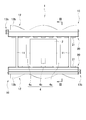
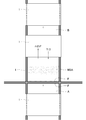
- the self-propelled cleaning robot 1 of the present embodiment includes a robot body 2 including a moving unit 4 for traveling on the target plane SF (see FIG. 5) of the structure SP, A pair of cleaning units 10 and 10 provided in the robot body 2 and a control unit 30 (see FIG. 1) for controlling the movement of the moving means 4 and the pair of cleaning units 10 and 10 are provided.
- the control unit 30 includes a posture control unit 35 that detects the posture of the robot body 2.
- the posture control unit 35 can detect whether the robot body 2 is lifted, specifically, whether the pair of cleaning units 10 and 10 are lifted from the target plane SF of the solar cell SP.
- the self-propelled cleaning robot 1 of the present embodiment is characterized in that the control unit 30 can detect the lifting of the robot body 2. First, an outline of the self-propelled cleaning robot 1 will be described. To do.
- the robot body 2 includes moving means 4 for moving the self-propelled cleaning robot 1 along the target plane SF of the structure SP to be cleaned.
- the moving means 4 includes a pair of side drive wheels 4a and 4a and one intermediate drive wheel 4b. Specifically, the pair of side drive wheels 4a and 4a and the intermediate drive wheel 4b are arranged to form a triangle in plan view (see FIG. 2). For this reason, the self-propelled cleaning robot 1 can be stably arranged on the target plane SF.
- the pair of side drive wheels 4a and 4a employs general wheels that can only rotate around the rotation axis, but the intermediate drive wheel 4b employs omni wheels (omnidirectional wheels). Yes.
- all the drive wheels 4a and 4b of the moving means 4 are connected to the drive motor 4m, respectively, so that each drive motor 4m can independently drive the drive wheels 4a and 4b.
- the operating states of all the drive motors 4m are controlled by the control unit 30 provided in the robot body 2. For this reason, if the control part 30 controls the operating state of each drive motor 4m, the self-propelled cleaning robot 1 can be moved linearly or turned.
- the direction in which the side surface where the pair of side drive wheels 4 a and 4 a are not provided corresponds to the front-rear direction of the self-propelled cleaning robot 1.
- the intermediate drive wheel 4b side (lower side in FIG. 2) is referred to as a rear portion with respect to the pair of side drive wheels 4a and 4a, and the opposite side (in FIG. 2).
- the upper part is called the front part.
- each drive motor 4m is controlled by the control unit 30, and the movement of the self-propelled cleaning robot 1 is controlled.
- the self-propelled cleaning robot 1 may store a movement path in the control unit 30 and automatically move on the target plane SF along the movement path. Further, the movement of the self-propelled cleaning robot 1 may be controlled by supplying a signal to the control unit 30 from the outside. For example, the movement of the self-propelled cleaning robot 1 may be controlled by remote control using a remote controller or the like.
- the drive wheels 4 are not limited to the above-described configuration, and may be configured so that the self-propelled cleaning robot 1 can be moved linearly or turned.
- the omni wheel that is the intermediate drive wheel 4b may not be used as a drive wheel, but only a pair of drive wheels 4a and 4a may be used as drive wheels.
- a passive wheel may be employed for the intermediate drive wheel 4b.
- the moving direction of the self-propelled cleaning robot 1 can be freely changed by adjusting the rotational speeds of the pair of drive wheels 4a and 4a.
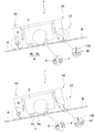
- the pair of cleaning parts 10 and 10 are provided at the front part and the rear part of the robot body part 2, respectively.
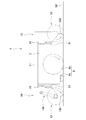
- each cleaning unit 10 is connected to the robot body 2 by a frame 11.
- the cleaning unit 10 includes a brush 12.
- the brush 12 includes a shaft portion 12a and a pair of brush portions 12b and 12b provided on the outer peripheral surface of the shaft portion 12 (FIG. 3).
- Both ends of the shaft portion 12a are rotatably supported by the frame of the cleaning unit 10. Moreover, when the self-propelled cleaning robot 1 is placed on the target plane SF, the axial direction thereof is provided so as to be substantially parallel to the target plane SF.
- the pair of brush portions 12b and 12b are formed by arranging a plurality of brushes along the axial direction.
- Each brush portion 12b is provided such that the position of the brush is displaced along the circumferential direction as it moves in the axial direction of the shaft portion 12a (see FIGS. 2 and 4).
- each brush portion 12b is formed in a spiral shape on the side surface of the shaft portion 12a.
- the pair of brush portions 12b and 12b are arranged to form a double helix. That is, the pair of brush portions 12b and 12b are formed such that the brushes of the pair of brush portions 12b and 12b are rotated 180 degrees with respect to each other in the cross section orthogonal to the axial direction of the shaft portion 12a. (See FIG. 4).
- the cleaning part 10 is provided with the brush drive part 13 which rotates the axial part 12a of the brush 12 around an axis
- the brush drive unit 13 includes a brush drive motor 13a, and the main shaft of the brush drive motor 13a is connected to the end of the shaft 12a of the brush 12 by a belt pulley mechanism 13b.
- the operating state of the brush drive motor 13 a is controlled by the control unit 30. For this reason, if the brush drive motor 13a is operated by the control part 30, the drive force will be transmitted to the axial part 12a of the brush 12 via the belt pulley mechanism 13b, and the brush 12 can be rotated.
- the length of the brush which comprises a pair of brush parts 12b and 12b is not specifically limited.
- the tip of the brush is formed to a length that can sweep the target plane SF and clean it.
- the target plane SF is the surface of a solar cell module in which a plurality of solar cells are arranged, even when the pair of side drive wheels 4a and 4a are placed on the frame formed on the edge of the solar cell.
- the tip of the brush only needs to be formed to a length that can sweep and clean the target plane SF.
- the length of the brush is preferably about 45 to 47 mm.
- this is determined in accordance with other parameters of the self-propelled cleaning robot 1, such as the rigidity of the brush, and needless to say, it is not limited to the above-mentioned dimensions. For example, if the length of the brush is made longer than the above-mentioned 47 mm, the brush 12 is less likely to float due to the tilt of the robot body 2.
- the length of the brush is made extremely long, a self-propelled cleaning robot
- the running performance of the self-propelled cleaning robot 1 significantly decreases. there's a possibility that.
- the load torque in each drive motor 4m of the brush drive motor 13m and the drive wheel 4 increases, which causes a problem of increasing power consumption. Therefore, the length of the brush may be appropriately set in accordance with the target plane SF to be cleaned by the self-propelled cleaning robot 1 and its environment.
- the brush of each brush part 12b does not need to arrange
- the brush may be arranged in a straight line along the axial direction of the shaft portion 12b, and is not particularly limited.
- the cleaning unit 10 cleans the target plane SF with the brush 12
- the method by which the cleaning unit 10 cleans the target plane SF is not particularly limited.
- the cleaning unit 10 is provided with a watering device (spray nozzle, etc.) and a wiper blade (squeegee) in addition to the brush 12, or a watering device (spray nozzle, etc.) and a wiper blade (squeegee) instead of the brush 12.
- a vacuum cleaner suction type vacuum cleaner
- only the vacuum cleaner suction type vacuum cleaner
- control unit 30 includes a movement control unit 31, a brush control unit 32, and an attitude control unit 35.
- the movement control unit 31 controls and monitors the operation of each drive motor 4m that drives the pair of side drive wheels 4a and 4a and the intermediate drive wheel 4b in the moving means 4.
- the movement control unit 31 controls the operation of the three drive motors 4m to control the movement direction and movement speed of the robot body 2, that is, the movement direction and movement speed of the self-propelled cleaning robot 1.
- the self-propelled cleaning is performed when each drive motor 4m is operated so that the moving speeds (specifically, the rotational speed (rotational speed) ⁇ the peripheral length of the drive wheels) of all the drive wheels 4 are the same.
- the robot 1 can be moved straight ahead.
- each drive motor 4m is operated so as to cause a difference in moving speed between the pair of side drive wheels 4a, 4a, the self-propelled cleaning robot 1 can be moved to turn.
- the movement control unit 31 moves so that one of the cleaning units 10 passes through the position where the lifting is detected after the lifting is canceled. 4 is controlled.
- the robot body is detected after the lift is detected after the lift is detected.
- the operation of the moving means 4 is controlled so that the part 2 moves backward.
- the cleaning unit 10 at the rear part can be passed again to the place where the lifting is detected.
- the cleaning unit 10 is provided only in the front part of the robot body 2
- the robot body 2 is turned 180 degrees and then moved forward.
- the operation of the moving means 4 is controlled. Then, the cleaning unit 10 can be passed again to the place where the lift is detected.
- the brush control unit 32 controls and monitors the operation of the brush drive motor 13a.
- the configuration of the brush control unit 32 is not particularly limited, but preferably has a current detection function for detecting a current value flowing through the brush drive motor 13a.
- the brush control unit 32 also has a function of detecting a frictional force against the rotation of the brush 12 based on a current value supplied to the brush drive motor 13a. In order to detect the frictional force of the brush 12, it is necessary to detect the value of the current flowing through the brush drive motor 13a. Note that this current value usually varies slightly due to the influence of dirt on the cleaning surface, the characteristics of the brush, and the like, even without brush lifting.
- the rotational speed of the brush drive motor 13a is controlled by PWM control, the voltage is applied as a rectangular wave to the brush drive motor 13a, so that the current also changes according to the change in voltage.
- the current value flowing through the brush drive motor 13a varies depending on various factors, in order to grasp the contact state of the brush from the current value, it is caused by factors other than the variation of the frictional force of the brush 12. It is necessary to eliminate fluctuations in the current value.
- the method for removing such a variation factor is not particularly limited.
- the measured current value is filtered to remove variations other than the frequency indicating the change in the contact state of the brush, or the current value is differentiated.
- the posture control unit 35 detects the posture of the robot body 2. Specifically, it detects whether the robot body 2 is lifted, that is, whether one of the pair of cleaning parts 10 and 10 is lifted from the target plane SF.
- the fact that one of the pair of cleaning parts 10 and 10 is lifted from the target plane SF is not only when the tip of the brush part 12b of the brush 12 is completely separated from the target plane SF, but is slightly in contact. It is a concept that includes states. That is, even if the tip of the brush portion 12b of the brush 12 is not completely separated from the target plane SF, the amount of deflection of the brush portion 12b of the brush 12 more than a certain amount (the brush portion 12b of the brush 12 that is deflected by being pressed against the target plane SF). When the amount of deflection) decreases, the cleaning ability decreases. Thus, even if the brush portion 12b of the brush 12 is in contact with the target plane SF, the state in which the cleaning ability by the brush 12 is reduced is included in the state in which the lifting occurs in the present specification.
- the attitude control unit 35 includes a tilt sensor 36 that detects the tilt of the robot body 2 as a lift sensor that detects the lift of the pair of cleaning units 10 and 10.
- the tilt sensor 36 is a sensor that detects how much the tilt of the robot body 2 in the front-rear direction is tilted with respect to the horizontal.
- the inclination sensor 36 is electrically connected to an analysis unit 37 of the posture control unit 35 and is configured to detect whether or not the robot body unit 2 is lifted by the analysis unit 37.
- the analysis unit 37 has a function of transmitting a lift signal to the movement control unit 31 when the lift occurs, and transmitting a return signal to the movement control unit 31 when the lift is eliminated.
- the method for determining whether or not the analysis unit 37 is lifted is not particularly limited.
- the following method can be employed.
- the analysis unit 37 stores the tilt of the robot body 2 detected by the tilt sensor 36 as a reference value.
- the inclination detected by the inclination sensor 36 is compared with a reference value, and if the deviation from the reference value is equal to or greater than a predetermined angle, it is determined that the lift has occurred.
- the reference value (that is, the mounting angle of the solar array) is usually about 15 to 20 degrees. It is. In this case, it is possible to determine that the lift has occurred when the inclination increases by about 1 degree or more from the reference value.
- the state in which the inclination is increased by about 1 degree or more from the reference value is the degree of inclination of the robot body 2 when the pair of side drive wheels 4a and 4a move from the surface of the solar cell to the frame (FIG. 9 ( A)).
- the inclination of the robot body 2 that the analysis unit 37 determines that the lift has occurred is referred to as a lift angle.
- the lifting angle can be set as appropriate depending on the size and shape of the self-propelled cleaning robot 1 and the state of the target plane.
- the reference value is stored in the storage unit 38.
- the reference value may be used.
- the target plane SF is the surface of a solar cell array in which rectangular solar cells are arranged side by side, and the self-propelled cleaning robot 1 runs along the longitudinal direction of the solar cell module on the surface of this solar cell array.
- the self-propelled cleaning robot 1 of the present embodiment has a pair of cleaning parts 10 and 10 before and after the robot body part 2, and usually the light receiving surface of the solar cell module is cleaned by both the cleaning parts 10. It will be explained on the assumption that
- the self-propelled cleaning robot 1 moves along the longitudinal direction of the solar cell module A
- the solar cell module A receives light by the cleaning unit 10 disposed in front of the robot body 2.
- the surface SF that is, the target plane SF
- the cleaning unit 10 disposed at the rear of the robot body 2 cleans the portion cleaned by the cleaning unit 10 at the front. That is, the target plane SF of the solar cell module A is cleaned twice by the cleaning unit 10.
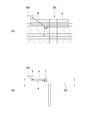
- the self-propelled cleaning robot 1 moves from the solar cell module A to the solar cell module B.
- the target plane SF of the solar cell module A and the target plane SF of the solar cell module B are positioned on substantially the same plane, the solar cell module A and the solar cell When climbing over the frame F of the module B, the tilt angle of the robot body 2 is smaller than the lift angle. Then, since the analysis part 37 judges that the lift has not arisen, even if it moves to the solar cell module B, the self-propelled cleaning robot 1 continues the movement along a longitudinal direction as it is (refer FIG. 6).
- the brush 12 of the cleaning unit 10 at the front part of the robot body 2 is in a state of being lifted on the target plane SF of the solar cell module B (see the inside of FIG. 9B). Then, until the return signal is transmitted to the movement control unit 31, the target plane SF of the solar cell module B is not cleaned by the cleaning unit 10 in the front part of the robot body 2. This uncleaned portion is referred to as a poorly cleaned portion NSA (see FIG. 8).
- the self-propelled cleaning robot 1 stops once and moves in the reverse direction when it moves through the poorly cleaned portion NSA until the rear cleaning portion 10 passes. (See FIGS. 6 and 8). That is, the poorly cleaned part NSA is once cleaned by the cleaning part 10 at the rear part of the self-propelled cleaning robot 1 and then cleaned again by the cleaning part 10 at the rear part. Then, when the cleaning of the poorly cleaned part NSA by the cleaning part 10 at the rear part is finished, the self-propelled cleaning robot 1 temporarily stops and starts moving forward again, so that the solar cell module B is moved along the longitudinal direction. Cleaning of the target plane SF is continued.
- the self-propelled cleaning robot 1 of the present embodiment when the lift occurs and the poorly cleaned portion NSA is formed, the lift is eliminated, and then the poorly cleaned portion NSA is cleaned by the cleaning unit 10. Therefore, even if the lifting occurs, the poorly cleaned portion NSA can be cleaned to the same extent as other portions.
- the movement of the self-propelled cleaning robot 1 is controlled so as to perform cleaning again only when the lift occurs, that is, when the poorly cleaned portion NSA is formed. For this reason, since the time of cleaning work can be shortened compared with the case where it always re-cleans in the place where a lift may occur, work efficiency can be improved and the cost required for cleaning work can be suppressed. .
- the step formed between the solar cell module A and the solar cell module B is 5 mm, and a pair of lateral drives are performed from the shaft portion 12a of the brush 12.
- the distance to the wheels 4a, 4a (the distance in the front-rear direction) is 205 mm, the distance from the intermediate drive wheel 4b to the pair of side drive wheels 4a, 4a is 93 mm, and the diameter of the brush 12 is 110 mm.
- the range of 180 to 280 mm from the frame F is the poorly cleaned portion NSA.
- the cleaning unit 10 As the re-cleaning operation, until the rear end of the self-propelled cleaning robot 1 passes through the poorly cleaned portion NSA, that is, after the rear end of the self-propelled cleaning robot 1 moves from the frame F by 280 mm or more, The backward movement of the self-propelled cleaning robot 1 is stored. Then, when the self-propelled cleaning robot 1 is lifted when moving from one solar cell to another solar cell, the poorly cleaned portion NSA can be cleaned by the cleaning unit 10.
- the lift detection sensor of the attitude control unit 35 is not limited to the tilt sensor 36 as described above.
- an accelerometer a contact distance meter (such as a dial gauge) that can detect the direction of gravity, or a non-contact distance meter (laser distance meter, It is also possible to use an ultrasonic distance meter.
- the traveling surface (target plane SF) is used as a reference. It is also possible to detect the posture of the robot body 2 and use it as a lift detection sensor.
- the brush control unit 32 may have a function of the lift detection sensor without providing the lift detection sensor as described above. That is, the brush control unit 32 may determine whether the front side portion or the rear side portion of the robot body 2 is lifted based on the current value supplied to the brush drive motor 13a.
- the reaction force that the brush portion 12b of the brush 12 receives from the target plane SF is reduced. Further, when the target plane SF is completely separated from the brush portion 12b of the brush 12, the reaction force that the brush portion 12b receives from the target plane SF becomes zero. Then, the frictional force acting between the brush portion 12b and the target plane SF is reduced or becomes zero, so that the current value flowing through the brush drive motor 13a is reduced. Therefore, it is possible to determine whether the front side portion or the rear side portion of the robot body 2 is lifted based on the current value.
- control unit 30 since it is not necessary to provide a special sensor for detecting lift, there is also an advantage that the configuration of the control unit 30 can be simplified.
- the method for removing noise from the current value is not particularly limited. For example, a large current that occurs in a short time by performing low-pass filter processing on the measured current value to remove high-frequency fluctuations or differentiating the current value with respect to time. It is possible to adopt a method of detecting only changes in
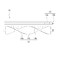
- Some solar cell modules for solar power generation and condensing mirrors for solar power generation change in inclination in order to maintain high power generation efficiency (see FIG. 10).
- the control unit 30 can grasp the inclination angle of the light-receiving surface and the change thereof as follows. Control can be implemented.
- ascertains the inclination angle of the light-receiving surface of a solar cell module or a condensing mirror, and its change is not specifically limited.
- a signal related to the inclination angle of the light receiving surface of the solar cell module or the collecting mirror is transmitted to the control unit 30 from the outside (for example, a control unit that controls the inclination angle of the light receiving surface of the solar cell module or the collecting mirror).
- the control unit 30 may grasp the inclination angle and the change thereof.
- the control unit 30 includes the attitude control unit 35 and the attitude control unit 35 includes the inclination sensor 36 as in the above example, the control unit 30 is based on the inclination detected by the inclination sensor 36. It is also possible for 30 to grasp the inclination angle and its change.
- the control unit 30 may grasp the tilt angle and the change thereof based on both the signal from the outside and the signal detected by the tilt sensor 36.
- a solar cell module for solar power generation and a condensing mirror for solar power generation are collectively referred to as a solar panel SS.
- the solar panel SS has a light receiving surface and an appropriate angle of solar radiation according to the movement of the sun (solar power modules such as solar power modules for solar power generation, trough type or dish type).
- the angle of the light receiving surface with respect to the horizontal (hereinafter referred to as the angle at which solar radiation is collected at the heat collecting part of the heat collecting tower, etc.)
- the inclination angle of the solar panel SS is controlled so as to change from moment to moment. For this reason, the inclination angle of the solar panel SS varies from horizontal to vertical.
- the solar panel SS may be tilted in only one direction (for example, only in the direction in which the right end (or left end) rises with respect to the horizontal in FIG. 10) or in both directions (in FIG. In some cases, both the right and left edges rise.
- the self-propelled cleaning robot 1 performs cleaning in a state where the inclination angle of the solar panel SS is easy to travel (for example, an angle from about 15 degrees from the horizontal).
- the cleaning by the self-propelled cleaning robot 1 is performed when the inclination angle of the solar panel SS is in an easy-to-travel angle, or the inclination angle of the solar panel SS is easy to travel for cleaning. It is implemented when adjusted to.
- the inclination angle of the solar panel SS is not always maintained at an angle at which the self-propelled cleaning robot 1 can easily travel until the entire surface of the light receiving surface is cleaned.
- the inclination angle of the solar panel SS is adjusted to an angle at which it is easy to travel for cleaning, the inclination angle of the solar panel SS is easy to travel until the self-propelled cleaning robot 1 cleans the entire light receiving surface. It does n’t mean that. This is because the time during which the inclination angle of the solar panel SS is easy to travel is in a state in which power generation is practically impossible, and it is preferable that the time during which the solar panel SS is easy to travel is as short as possible. It is.
- the solar panel SS when the inclination angle of the solar panel SS is adjusted for cleaning by the self-propelled cleaning robot 1, even if the self-propelled cleaning robot 1 is cleaning, if the cleaning time becomes long, the solar panel SS
- the inclination angle may change from an angle that is easy to travel to an angle that is suitable for power generation.
- the inclination angle of the solar panel SS is not adjusted for cleaning, as a matter of course, the inclination angle of the solar panel SS changes from an angle at which the solar panel SS can easily travel while the self-propelled cleaning robot 1 is cleaning. there is a possibility.
- the self-propelled cleaning robot 1 may fall from the solar panel SS. Therefore, in order to prevent the self-propelled cleaning robot 1 from falling, it is preferable to operate the self-propelled cleaning robot 1 as follows based on the inclination angle of the solar panel SS.
- the solar panel SS includes a robot base RB that houses the self-propelled cleaning robot 1, the operation of the self-propelled cleaning robot 1 is controlled as follows.
- the robot base RB stores the self-propelled cleaning robot 1 when the self-propelled cleaning robot 1 does not perform cleaning.
- the robot base RB is arranged so that its floor surface is flush with the surface of the solar panel SS, and the self-propelled cleaning robot 1 can move smoothly between the robot base RB and the surface of the solar panel SS. It is formed as follows.
- the analysis unit 37 described above stores the inclination angle of the solar panel SS in the self-propelled cleaning robot 1 in advance based on the signal from the inclination sensor 36. It is determined whether or not it is an angle that can be cleaned (for example, from the horizontal to about 15 degrees, which corresponds to the “state where the inclination angle of the plane of the structure is smaller than a predetermined angle” in the claims)
- the return signal is transmitted to the movement control unit 31 when the cleaning angle is reached from the inclined state.
- the movement control unit 31 keeps the return signal until a new signal (for example, a tilt start notice signal described later) is received.
- the inclination angle of the solar panel SS cannot be cleaned from an angle at which the solar panel SS can be cleaned with respect to the analysis unit 37 (for example, an angle of 15 degrees or more).
- An inclination notification signal for notifying the change (corresponding to “the state where the inclination angle of the plane of the structure becomes a predetermined angle or more” in the claims) is transmitted.
- the analysis unit 37 detects the tilt notification signal
- the tilt start notice signal is transmitted to the movement control unit 31.
- the movement control unit 31 keeps the inclination start notice signal until a new signal (for example, the above-described return signal) is received.
- the movement control unit 31 When the movement control unit 31 receives the cleaning start signal while holding the return signal, the movement control unit 31 moves so that the self-propelled cleaning robot 1 moves along the predetermined route on the solar panel SS.
- the means 4 is activated.
- the movement control unit 31 when the movement control unit 31 receives the tilt start notice signal, the movement control unit 31 operates the moving unit 4 so that the self-propelled cleaning robot 1 returns from the solar panel SS to the robot base RB through the shortest path. Keep it.
- the self-propelled cleaning robot 1 moves from the robot base RB onto the solar panel SS and moves along a predetermined route (arrow a in the figure).
- the surface of the solar panel SS can be cleaned along the route by the self-propelled cleaning robot 1 (see FIGS. 10A and 10B).
- the self-propelled cleaning robot 1 when the solar panel SS starts tilting while the self-propelled cleaning robot 1 is traveling on the surface of the solar panel SS, the self-propelled cleaning robot 1 returns to the robot base RB along the shortest path (arrow b in the figure). Then, when the solar panel SS is tilted, the self-propelled cleaning robot 1 can be prevented from falling from the solar panel SS (see FIGS. 10A and 10B).
- the self-propelled cleaning robot 1 automatically switches between the cleaning of the surface of the solar panel SS and the return to the robot base RB in accordance with the operation of the solar panel SS. Cleaning of the panel SS can be automated.
- the robot before the self-propelled cleaning robot 1 cleans the entire surface of the solar panel SS.
- the cleaning can be started from the previously cleaned position, which is preferable.
- the self-propelled cleaning robot 1 when the solar panel SS is adjusted to an angle at which the self-propelled cleaning robot 1 can easily travel for cleaning, that is, when a period for cleaning is specially provided, the self-propelled cleaning robot 1 is provided with the solar panel.
- the self-propelled cleaning robot 1 transmits a signal (cleaning completion signal) notifying that the movement is completed to an external control unit that controls the operation of the solar panel SS. It is preferable to do so.
- the external control unit starts adjusting the inclination angle of the solar panel SS for power generation. Then, when the solar panel SS starts adjusting the inclination angle, the self-propelled cleaning robot 1 can be prevented from falling from the solar panel SS.
- the analysis unit 37 determines the current inclination angle of the solar panel SS based on the signal of the inclination sensor 36, and the change in the inclination angle of the solar panel SS is based on the inclination notification signal from the external control unit.
- the current inclination angle of the solar panel SS is determined based on a signal from an external control unit, and the change of the inclination angle of the solar panel SS is grasped by the analysis unit 37 based on the signal of the inclination sensor 36.
- both the current inclination angle and the change in the inclination angle may be grasped by the analysis unit 37 based on a signal from the inclination sensor 36 or may be determined based on a signal from an external control unit.
- the cleaning by the self-propelled cleaning robot 1 as described above may be started by a person at an arbitrary time and time, or the cleaning is automatically started and ended at regular intervals. May be.
- the self-propelled cleaning robot 1 may be set to start cleaning when it is determined that the power generation output of the solar panel SS has decreased (that is, the surface of the solar panel SS has become dirty).
- the method for detecting that the power generation output of the solar panel SS has been reduced is not particularly limited, for example, in the case of solar power generation, it can be detected by the following method.
- the generated power (1) is calculated by multiplying the conversion efficiency inherent in the solar cell module being used by the amount of solar radiation detected by a solar radiation meter or the like. Further, the generated power (2) that decreases as the temperature rises is calculated by multiplying the temperature coefficient specific to the solar cell module being used by the surface temperature of the solar cell module. Therefore, by calculating (1)-(2), the generated power expected when the solar cell module is not dirty is obtained. Compare the generated power calculated in this calculation with the actual generated power at that time, and if the actual generated power is lower than a certain value, it is judged that the surface of the solar cell module is dirty. Then, the cleaning by the self-propelled cleaning robot 1 may be started at that time.
- the self-propelled cleaning robot 1 is held by the robot base RB has been described.
- the self-propelled cleaning robot 1 itself may increase the inclination of the solar panel SS. You may have a function which prevents falling. That is, the self-propelled cleaning robot 1 may have fixing means for fixing the self-propelled cleaning robot 1 itself to the solar panel SS.
- the self-propelled cleaning robot 1 stops traveling, and the self-propelled cleaning robot 1 is fixed to the solar panel SS by the fixing means. To do.
- the movement control unit 31 receives the return signal, the self-propelled cleaning robot 1 is released from the solar panel SS, and when the movement control unit 31 receives the cleaning start signal while holding the return signal, the self-propelled cleaning robot 1 The robot 1 starts cleaning. Then, the start stop of cleaning can be quickly switched while preventing the self-propelled cleaning robot 1 from falling.
- the method by which the fixing means prevents the self-propelled cleaning robot 1 from falling is not particularly limited.
- a method of adsorbing and fixing to the surface of the solar panel SS using a suction cup or the like, and a method of fixing by a member that engages with an edge of the solar panel SS such as a hook-shaped hook can be used.
- the structure SP for example, a solar panel SS
- the target plane SF is high in a state where the self-propelled cleaning robot 1 performs cleaning (that is, in a state where the cleaning is possible).
- the self-propelled cleaning robot 1 is disposed on a structure SP whose target plane SF is about 2 m or more from the ground, and whose height is reduced when the inclination angle is increased. Is done.
- the solar panel SS is arranged so that the inclination angle can be changed at the upper end of the column.
- the height of the support column is often about 5 m, and the height of the upper surface is about 5 m from the ground at a cleanable angle.
- the solar panel SS has a square shape with a side of about 10 m, and in this solar panel SS, a support column is connected to the center of the back surface. For this reason, when the inclination angle of the solar panel SS is increased, one end edge thereof is positioned in the vicinity of the ground. The following method is applied when the self-propelled cleaning robot 1 is arranged on such a structure SP.
- a target plane SF of a structure SP (hereinafter referred to as a solar panel SS) such as a solar panel SS has a cleanable angle
- the target plane SF is about 3 m or more from the ground.
- the person cannot arrange the self-propelled cleaning robot 1 on the target plane SF or the like.
- the inclination angle of the target plane SF is increased. That is, the inclination angle is increased so that the target plane SF is nearly vertical.
- a part of the target plane SF is arranged at a position close to the ground.
- the self-propelled cleaning robot 1 has the fixing means as described above, the self-propelled cleaning robot 1 is brought into contact with the target plane SF to operate the fixing means. Then, the self-propelled cleaning robot 1 can be fixed to the target plane SF by the fixing means. Therefore, the self-propelled cleaning robot 1 can be arranged on the target plane SF, and the target plane SF can be cleaned by the self-propelled cleaning robot 1 by setting the target plane SF to an inclination angle from that state.
- the robot base RB when the robot base RB is provided, the robot base RB is provided in a portion that is disposed at a position close to the ground when the inclination angle is increased in the target plane SF. Then, when the inclination angle of the target plane SF is increased, the self-propelled cleaning robot 1 can be disposed on the robot base RB. Therefore, the target plane SF can be cleaned by the self-propelled cleaning robot 1 by setting the target plane SF to an inclination angle from the state where the robot base RB is arranged on the target plane SF.
- the self-propelled cleaning robot 1 described above sequentially has the surface of each structure in a structure SP composed of a plurality of structures like a solar cell array composed of a plurality of solar cell modules. Suitable for cleaning.
- the above-described self-propelled cleaning robot 1 can simultaneously clean the surfaces of a plurality of structures constituting the structure SP, such as a solar cell array including a plurality of solar cell modules. If the traveling cleaning robot 1 has the following structure, cleaning becomes easier.
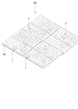
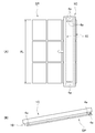
- the structure of the structure SP that is cleaned by the following self-propelled cleaning robots 1B to 1C is not particularly limited. However, it is a structure SP such as a solar cell array formed by arranging a plurality of structures such as solar cell modules in a lattice pattern, and is suitable for a structure SP formed to be longer in the horizontal direction than in the vertical direction. Yes.
- the vertical direction (that is, the direction in which the length is short) of the structure SP is referred to as the minor axis direction of the structure SP.
- the basic structures of the following self-propelled cleaning robots 1B to 1C are substantially the same as the self-propelled cleaning robot 1 described above. Only the part which has is demonstrated.
- the self-propelled cleaning robot 1 ⁇ / b> B has a longer width (that is, the axial direction of the brush 12 in the cleaning unit 10) than the self-propelled cleaning robot 1.
- the length of the brush 12 in the axial direction is longer than the length AL of the structure SP in the short axis direction (hereinafter simply referred to as the length AL of the structure SP). That is, the length of the brush 12 in the axial direction is set to such a length that the brush portion 12b of the brush 12 is in contact with the entire plurality of structures of the structure SP.
- the self-propelled cleaning robot 1B In the case of the self-propelled cleaning robot 1B having such a structure, the self-propelled cleaning robot 1 is placed on the target plane SF, and the axial direction of the brush 12 is matched with the short-axis direction of the structure SP. If the drive wheel 4a of the moving mechanism 4 is operated from this state, the self-propelled cleaning robot 1B can be moved in the width direction of the structure SP (in the left-right direction in FIG. 8). Can be cleaned.
- a self-propelled cleaning robot 1C shown in FIG. 12 is obtained by providing the above-described self-propelled cleaning robot 1B with an edge roller 4e, and other configurations are substantially the same as those of the self-propelled cleaning robot 1B. Is.
- the edge roller 4e is provided at a position in contact with the upper edge of the structure of the structure SP when the self-propelled cleaning robot 1C is disposed on the structure SP. That is, the self-propelled cleaning robot 1C is in a state of being caught on the structure SP by the edge roller 4e. For this reason, 1 C of self-propelled cleaning robots can be arrange
- the edge roller 4e is provided so that the rotation axis thereof is parallel to the target plane SF, and the structure of the structure SP when the self-propelled cleaning robot 1C moves in the width direction of the structure SP. It can be rolled on the upper edge. For this reason, even if the edge roller 4e is provided, the self-propelled cleaning robot 1C can move smoothly on the target plane SF of the structure SP.
- the self-propelled cleaning robot of the present invention is suitable as a robot for cleaning a solar cell array of a large-scale solar power generation facility, a condensing mirror of a solar thermal power generation facility, a light receiving surface of a solar water heater, and the like.
Abstract
段差が形成されていても平面を効率良く掃除することができる自走式掃除ロボットを提供する。 屋外に設置された平面を有する構造物上を自走して、構造物の平面を掃除するロボットであって、自走のための移動手段(4)が設けられたロボット本体(2)と、ロボット本体(2)の前方部および/または後方部に設けられた掃除部(10)と、移動手段(4)の作動を制御する制御部(30)と、を備えており、制御部(30)は、ロボット本体(2)の姿勢を検出する姿勢制御部(35)を備えており、姿勢制御部(35)が、ロボット本体(2)の前方部または後方部の浮き上がりを検出する浮き上がり検出センサ(36)を備えており、制御部(30)は、浮き上がり検出センサがロボット本体(2)の前方部または後方部の浮き上がりを検出すると、浮き上がりが解消された後、浮き上がりを検出した箇所(NSA)を掃除部(10)が通過するように移動手段(4)の作動を制御する。
Description
本発明は、自走式掃除ロボットに関する。さらに詳しくは、太陽光発電に使用する太陽電池アレイや太陽熱発電に使用する集光ミラーなどの表面を掃除するための自走式掃除ロボットに関する。
近年、再生可能エネルギを利用した発電の要求が高まっており、とくに太陽光を利用した太陽光発電や太陽熱発電には大きな注目が集まっている。
例えば、太陽光発電設備には、一般住宅に設けられる3~4キロワット程度の発電容量の設備から、商業用の1メガワットを超える発電容量を有する大規模な発電設備まである。また、太陽熱発電設備においても、1メガワットを超える発電容量を有する大規模な設備が多く、火力発電や原子力発電の代替発電施設として期待されている。
例えば、太陽光発電設備には、一般住宅に設けられる3~4キロワット程度の発電容量の設備から、商業用の1メガワットを超える発電容量を有する大規模な発電設備まである。また、太陽熱発電設備においても、1メガワットを超える発電容量を有する大規模な設備が多く、火力発電や原子力発電の代替発電施設として期待されている。
一方、太陽光発電や太陽熱発電などの太陽光を利用した発電では、太陽からの日射光を受けて発電する。このため、太陽電池アレイ(つまり太陽電池モジュール)や集光ミラーの受光面が汚れると、汚れの程度に応じて、太陽光発電においては太陽電池モジュールの受光面を構成するカバーガラスの光透過率が低下することによって、発電される電力量が減少する。また、太陽熱発電においては、集光ミラーの反射率が低下することによって、発電される電力量が減少する。つまり、太陽光発電や太陽熱発電では、太陽電池モジュールや集光ミラーの受光面が汚れていると、発電性能が大幅に低下する。このため、太陽電池アレイ等の受光面の汚れを除去するために、太陽電池アレイ等を適宜掃除することが重要になる。
一般住宅に設けられている設備であれば、定期的に人が掃除することも可能である。一方、大規模な太陽光発電設備の場合、その表面積は非常に大きくなるため、人が掃除して太陽電池アレイ表面の汚れを除去することは実質的に困難である。例えば、1メガワットの太陽光発電設備の場合、1枚あたり100ワットの発電出力の太陽電池モジュールから構成されているとすると、太陽光発電設備全体では、太陽電池モジュールは1万枚に及ぶ。1枚の太陽電池モジュールの面積が1平方メートルの場合、掃除すべき面積は10000平方メートルに達する。そして、太陽光発電設備の場合、複数枚の太陽電池モジュールを1セットとする太陽電池アレイが複数設けられるのであるが、この太陽電池アレイの面積は、現場の種々の条件によって異なるが、概ね50平方メートルから1000平方メートルになる。したがって、大規模な太陽光発電設備では、自動または遠隔操作で太陽電池アレイ等を走行させることができる自走式掃除ロボットが必要となる。
ところで、自走式掃除ロボットとして、最近では、建物の床などを自動で掃除するものが種々開発されており(例えば特許文献1)、かかる自走式掃除ロボットを、太陽電池アレイ等を掃除するためのロボットとして採用することも考えられる。
しかるに、太陽光発電設備等では、複数枚の太陽電池モジュール等を並べて太陽電池アレイ等が形成されているため、太陽電池モジュール等の間を移動しながら順次太陽電池モジュール等を掃除することが必要になる。しかし、設置する場所の凹凸や施工誤差などによって、隣接する太陽電池モジュール等の間で段差ができてしまう場合がある。
これまで開発されている自走式掃除ロボットは段差がほとんどない状態の床面などを掃除することを前提に設計されている。このため、かかる段差があると、その段差を移動する際に、自走式掃除ロボットの掃除部が太陽電池モジュール等から浮き上がってしまい、浮き上がっている期間は太陽電池モジュール等の表面を掃除できない。
また、段差だけでなく、太陽電池モジュール(集光ミラーも同様)間の隙間(数ミリ~数センチ程度)がある場合、隙間に車輪が嵌る位置にきたときに、ロボットの車体が傾き、ブラシと清掃面の距離が離れて正常に清掃できなくなることも生じる。
つまり、これまで開発されている自走式掃除ロボットに太陽電池アレイや太陽熱発電における集光ミラーを掃除させた場合には、太陽電池アレイや集光ミラーの全面を掃除することは難しく、掃除していない部分ができてしまい、発電性能の大幅な低下をまねく恐れがある。特に太陽電池モジュールは、その表面の一部のみが汚れていても、そのモジュール全体の出力に大きく影響するという特性がある。つまり汚れが付着している面積と発電出力が低下する量は非線形の関係となる。したがって、太陽電池モジュール表面の掃除では、掃除が不十分な領域をつくることなく、太陽電池の表面全体を一様に掃除することが重要である。例えば、汚れた1枚の太陽電池モジュールのうちの半分の面積のみを掃除した場合と、全体を掃除した場合とを比較する。この場合、半分の面積のみを掃除した場合は、掃除によって増加する発電出力(掃除によって回復する発電性能)が全体を掃除した場合に増加する発電出力の半分になるのではなく、それを大きく下回る発電出力の増加しか得られない。
一方、掃除できない部分が形成されることを見越して、自走式掃除ロボットに同じ場所を一度以上往復させて掃除させれば上記のような問題は解決されるものの、掃除作業の時間が長くなってしまい、作業効率が低下してしまい、掃除作業に要するコストも大幅に増大する。
本発明は上記事情に鑑み、段差が形成されていても平面を効率良く掃除することができる自走式掃除ロボットを提供することを目的とする。
第1発明の自走式掃除ロボットは、屋外に設置された平面を有する構造物上を自走して、該構造物の平面を掃除するロボットであって、自走のための移動手段が設けられたロボット本体と、該ロボット本体の前方部および/または後方部に設けられた掃除部と、前記移動手段の作動を制御する制御部と、を備えており、該制御部は、前記ロボット本体の姿勢を検出する姿勢制御部を備えており、該姿勢制御部が、前記ロボット本体の前方部または後方部の浮き上がりを検出する浮き上がり検出センサを備えており、前記制御部は、前記浮き上がり検出センサが前記ロボット本体の前方部または後方部の浮き上がりを検出すると、該浮き上がりが解消された後、浮き上がりを検出した箇所を前記掃除部が通過するように前記移動手段の作動を制御することを特徴とする。
第2発明の自走式掃除ロボットは、第1発明において、前記浮き上がり検出センサは、前記ロボット本体の傾きを検出する傾斜センサであることを特徴とする。
第3発明の自走式掃除ロボットは、第1発明において、前記掃除部が、モータによって回転するブラシを備えており、前記浮き上がり検出センサは、前記モータの作動状態を検出するモータ監視センサであることを特徴とする。
第4発明の自走式掃除ロボットは、平面を有し該平面の水平に対する傾斜角度が変化する屋外に設置された構造物上を自走して、該構造物の平面を掃除するロボットであって、自走のための移動手段が設けられたロボット本体と、該ロボット本体の前方部および/または後方部に設けられた掃除部と、前記移動手段の作動を制御する制御部と、を備えており、該制御部は、前記構造物の平面の傾斜角度が所定の角度より小さい状態では前記平面上を走行し、前記構造物の平面の傾斜角度が所定の角度以上の状態になることを検出すると前記平面上の走行を停止するように前記移動手段を作動させることを特徴とする。
第5発明の自走式掃除ロボットは、第4発明において、前記構造物が該自走式掃除ロボットを保持しておくベースを備えている場合において、前記制御部は、前記構造物の平面の傾斜角度が所定の角度以上の状態になることを検出すると、前記平面上から前記ベースに移動し、前記構造物の平面の傾斜角度が所定の角度より小さくなると前記ベースから前記平面上に移動し該平面上を走行するように前記移動手段を作動させることを特徴とする。
第6発明の自走式掃除ロボットは、第4発明において、前記ロボット本体が、該ロボット本体を前記構造物に固定する固定手段を備えており、前記制御部は、前記構造物の平面の傾斜角度が所定の角度以上の状態になることを検出すると、前記平面上の走行を停止させて前記固定手段によって前記構造物に前記ロボット本体を固定し、前記構造物の平面の傾斜角度が所定の角度より小さくなると前記固定手段による前記構造物に対する前記ロボット本体の固定を解放して該平面上を走行させることを特徴とする。
第7発明の自走式掃除ロボットは、第1乃至第6発明のいずれかにおいて、前記構造物が、複数枚の太陽電池モジュールまたはミラーを並べて形成された太陽電池アレイまたは集光ミラーであることを特徴とする。
第1発明によれば、浮き上がりが解消された後に、浮き上がりの生じた箇所に掃除部を通過させるので、浮き上がりにより掃除できない部分ができることを防止することができる。しかも、浮き上がりが生じた場合にのみ、再度掃除部を浮き上がりの生じた箇所を通過させる。つまり、浮き上がりが生じた場合にのみ再掃除するので、常時浮き上がりが発生する可能性がある場所で常時再掃除する場合に比べて、掃除作業の時間を短くできる。したがって、作業効率を向上させることができ、掃除作業に要するコストを抑えることができる。
第2発明によれば、ロボット本体の傾きを検出するだけであるので、簡単な構成で浮き上がりの発生を検出することができる。
第3発明によれば、モータの負荷トルクを検出して浮き上がりを検出するので、浮き上がりを検出するための特別なセンサを設ける必要がないから、制御部の構成を簡単にすることができる。
第4発明によれば、構造物の傾斜角度が所定の角度以上の状態、つまり、清掃できない角度となることを検出すると平面上の走行を停止するので、平面上からロボットが落下することを防ぐことができる。
第5発明によれば、構造物の傾斜角度が所定の角度以上となる前にロボットがベースに保持される状態となるので、構造物の傾斜角度が大きくなっても、平面上からロボットが落下することを確実に防ぐことができる。また、構造物の傾斜角度が小さくなると、ベースから平面上にロボットが移動するので、平面の掃除を開始することができる。つまり、構造物の傾斜に応じて、平面の掃除とベースへの復帰を自動で切り替えて移動させることができるので、構造物の平面の掃除を自動化することも可能となる。
第6発明によれば、構造物の傾斜角度が所定の角度以上となる前に、ロボットが吸着手段によって構造物に固定された状態となるので、構造物の傾斜角度が大きくなっても、平面上からロボットが落下することを確実に防ぐことができる。また、構造物の傾斜角度が小さくなると、固定手段による固定が解除されて、ロボットが平面上を走行できる状態となるので、平面の掃除を開始することができる。つまり、構造物の傾斜に応じて、平面の掃除と構造物への固定を自動で切り替えることができるので、構造物の平面の掃除を自動化することも可能となる。
第7発明によれば、複数枚の太陽電池モジュールやミラー間に段差や隙間があっても掃除が不十分な部分ができることを防止することができるから、発電性能の低下を防止することができる。
本発明の自走式掃除ロボットは、屋外に設置されている構造物の平面状の部分を掃除するためのロボットであって、平面状の部分に段差などがあっても効率良く掃除作業を行うことができるようにしたことに特徴を有している。
本発明の自走式掃除ロボットが掃除する対象となる構造物は、平面を有する構造物であって、この平面に沿って自走式掃除ロボットが移動できる構造物であればよく、とくに限定されない。例えば、大規模な太陽光発電設備の太陽電池アレイや、太陽熱発電施設における集光ミラー、太陽熱温水器などを挙げることができる。また、掃除する平面は、太陽電池アレイの表面(つまり、太陽電池モジュールの受光面)や集光ミラーの表面(つまり、ミラーの受光面)、太陽熱温水器の受光面等を挙げることができる。なお、本明細書において、平面とは、太陽電池アレイのような平らな面としての平面と、集光ミラーのように曲率半径が大きくほぼ平らに近い曲面も含む概念である。
以下では、太陽電池アレイや、太陽熱発電施設における集光ミラー、太陽熱温水器を構造物SPという。また、掃除する対象となる構造部物SPの表面(つまり上記各受光面)を対象平面SFという。
(自走式掃除ロボット1の説明)
図2に示すように、本実施形態の自走式掃除ロボット1は、構造部物SPの対象平面SF(図5参照)上を走行するための移動手段4を備えたロボット本体部2と、このロボット本体部2に設けられた一対の掃除部10,10と、移動手段4や一対の掃除部10,10の作動を制御する制御部30(図1参照)とを備えている。
図2に示すように、本実施形態の自走式掃除ロボット1は、構造部物SPの対象平面SF(図5参照)上を走行するための移動手段4を備えたロボット本体部2と、このロボット本体部2に設けられた一対の掃除部10,10と、移動手段4や一対の掃除部10,10の作動を制御する制御部30(図1参照)とを備えている。
本実施形態の自走式掃除ロボット1では、制御部30がロボット本体部2の姿勢を検出する姿勢制御部35を備えている。この姿勢制御部35は、ロボット本体部2の浮き上がり、具体的には、一対の掃除部10,10が太陽電池SPの対象平面SFから浮き上がっているか否かを検出することができるものである。
本実施形態の自走式掃除ロボット1は、制御部30がロボット本体部2の浮き上がりを検出できるようにした点に特徴を有しているが、まず、自走式掃除ロボット1の概略を説明する。
(ロボット本体部2)
図2および図3に示すように、ロボット本体部2は、掃除する対象である構造物SPの対象平面SFに沿って自走式掃除ロボット1を移動させるための移動手段4を備えている。
図2および図3に示すように、ロボット本体部2は、掃除する対象である構造物SPの対象平面SFに沿って自走式掃除ロボット1を移動させるための移動手段4を備えている。
この移動手段4は、一対の側方駆動輪4a,4aと、一つの中間駆動輪4bと、を備えている。具体的には、一対の側方駆動輪4a,4aと中間駆動輪4bとによって、平面視で三角形を形成するように配置されている(図2参照)。
このため、自走式掃除ロボット1を対象平面SF上に安定した状態で配置することができる。
このため、自走式掃除ロボット1を対象平面SF上に安定した状態で配置することができる。
また、一対の側方駆動輪4a,4aには、回転軸周りの回転しかできない一般的な車輪を採用しているが、中間駆動輪4bにはオムニホイール(全方向移動車輪)を採用している。しかも、移動手段4の全ての駆動輪4a,4bはそれぞれ駆動モータ4mに接続されており、各駆動モータ4mが独立して各駆動輪4a,4bを駆動させることができるようになっている。そして、全ての駆動モータ4mは、ロボット本体部2に設けられた制御部30によってその作動状態が制御されている。
このため、制御部30によって各駆動モータ4mの作動状態を制御すれば、自走式掃除ロボット1を直線的に移動させたり、旋回移動させたりすることができる。
このため、制御部30によって各駆動モータ4mの作動状態を制御すれば、自走式掃除ロボット1を直線的に移動させたり、旋回移動させたりすることができる。
なお、ロボット本体部2において、一対の側方駆動輪4a,4aが設けられていない側面が存在する方向(図2では上下方向)が、自走式掃除ロボット1の前後方向に相当する。以下では、自走式掃除ロボット1の前後方向において、一対の側方駆動輪4a,4aに対して中間駆動輪4b側(図2では下側)を後方部といい、反対側(図2では上側)を前方部という。
また、制御部30によって各駆動モータ4mの作動状態が制御され、自走式掃除ロボット1の移動が制御される。この自走式掃除ロボット1は、制御部30に移動経路を記憶させておきこの移動経路に沿って自動で対象平面SF上を移動するようにしてもよい。また、制御部30に対して外部から信号を供給して自走式掃除ロボット1の移動を制御してもよい。例えば、リモコン等によって遠隔操作して自走式掃除ロボット1の移動を制御してもよい。
さらに、駆動輪4は上記のごとき構成に限られず、自走式掃除ロボット1を直線的に移動させたり、旋回移動させたりすることができるように構成されていればよい。例えば、中間駆動輪4bであるオムニホイールを駆動輪とせず、一対の駆動輪4a,4aだけを駆動輪としてもよい。また、オムニホイールに代えて、中間駆動輪4bに受動車輪(キャスター)を採用してもよい。この場合でも、一対の駆動輪4a,4aの回転数を調整すれば、自走式掃除ロボット1の移動方向を自在に変更することができる。さらに、通常の車両と同様の構造としてもよい。つまり、車輪を4輪設けて、その前方(または後方)の2輪を操舵輪として他の車輪を駆動輪としたり、4輪駆動としたりしてもよい。
(掃除部10)
図2~図4に示すように、一対の掃除部10,10は、それぞれロボット本体部2の前方部および後方部に設けられている。
図2~図4に示すように、一対の掃除部10,10は、それぞれロボット本体部2の前方部および後方部に設けられている。
図2および図3に示すように、各掃除部10は、フレーム11によってロボット本体部2に連結されている。この掃除部10は、ブラシ12を備えている。このブラシ12は、軸部12aと、この軸部12の外周面に設けられた一対の刷毛部12b,12bと、を備えている(図3)。
軸部12aは、その両端部が掃除部10のフレームに回転可能に支持されている。しかも、自走式掃除ロボット1を対象平面SF上に載せたときに、その軸方向が対象平面SFとほぼ平行となるように設けられている。
一対の刷毛部12b,12bは、複数の刷毛を軸方向に沿って並べて形成されたものである。各刷毛部12bは、刷毛の位置が、軸部12aの軸方向に移動するに従って周方向に沿ってズレるように設けられている(図2および図4参照)。言い換えれば、各刷毛部12bは、軸部12aの側面に螺旋状に形成されている。しかも、一対の刷毛部12b,12bで二重螺旋を形成するように配設されている。つまり、軸部12aの軸方向と直交する断面において、一対の刷毛部12b,12bの各刷毛が互いに180度回転した位置となるように、一対の刷毛部12b,12bが形成されているのである(図4参照)。
また、図4に示すように、掃除部10は、ブラシ12の軸部12aを軸周りに回転させるブラシ駆動部13を備えている。具体的には、このブラシ駆動部13は、ブラシ駆動モータ13aを備えており、ブラシ駆動モータ13aの主軸がブラシ12の軸部12aの端部とベルトプーリ機構13bによって連結されている。そして、ブラシ駆動モータ13aは、制御部30によってその作動状態が制御されている。
このため、制御部30によってブラシ駆動モータ13aを作動させれば、その駆動力がベルトプーリ機構13bを介してブラシ12の軸部12aに伝達され、ブラシ12を回転させることができる。
このため、制御部30によってブラシ駆動モータ13aを作動させれば、その駆動力がベルトプーリ機構13bを介してブラシ12の軸部12aに伝達され、ブラシ12を回転させることができる。
なお、一対の刷毛部12b,12bを構成する刷毛の長さはとくに限定されない。自走式掃除ロボット1が対象平面SFを走行している状態において、刷毛の先端部が対象平面SFを掃いて掃除できる程度の長さに形成されていればよい。例えば、対象平面SFが複数の太陽電池が並んだ太陽電池モジュールの表面の場合には、太陽電池の端縁に形成されているフレーム上に一対の側方駆動輪4a,4aが載った状態でも、刷毛の先端部が対象平面SFを掃いて掃除できる程度の長さに形成されていればよい。具体的には、太陽電池モジュールの表面からフレームの上端までの距離が1.5mmであって、自走式掃除ロボット1を対象平面SF上に載せたときに、対象平面SFから軸部12aの外周面までの距離が37mmであれば、刷毛の長さは45~47mm程度が好ましい。
ただし、これは刷毛の剛性等、自走式掃除ロボット1の他のパラメータに応じて決定されるものであり、上述の寸法に限定されるものでないことはいうまでもない。例えば、刷毛の長さを上述の47mmよりも長くすれば、ロボット本体2の傾きによるブラシ12の浮きは生じにくくなるが、一方で、刷毛の長さを極端に長くすると、自走式掃除ロボット1が対象平面SF上を走行する際(側方駆動輪4a,4aおよび中間駆動輪4bが同一の平面に接触している状態)の掃除能力や自走式掃除ロボット1の走行性能が著しく低下する可能性がある。また、ブラシ駆動モータ13mおよび駆動輪4の各駆動モータ4mにおける負荷トルクが増大し、消費電力の増加を招くという問題が生じる。したがって、自走式掃除ロボット1が掃除する対象平面SFやその環境等に合わせて、刷毛の長さは適宜適切な長さにすればよい。
また、各刷毛部12bの刷毛は螺旋状に配置しなくてもよい。例えば、刷毛を軸部12bの軸方向に沿って直線状に並ぶように配置してもよく、とくに限定されない。
さらに、上記例では、掃除部10が、ブラシ12によって対象平面SFを清掃する場合を説明したが、掃除部10が対象平面SFを清掃する方法はとくに限定されない。例えば、掃除部10に、ブラシ12に加えて散水装置(スプレーノズル等)とワイパーブレード(スクイジー)を設けたり、ブラシ12の代わりに散水装置(スプレーノズル等)とワイパーブレード(スクイジー)を設けたりしてもよい。また、ブラシ12に加えてバキュームクリーナー(吸引式掃除機)を設けてもよいし、ブラシ12を設けずにバキュームクリーナー(吸引式掃除機)だけを設けてもよい。
(制御部30)
つぎに、制御部30について説明する。
図1に示すように、制御部30は、移動制御部31、ブラシ制御部32および姿勢制御部35を備えている。
つぎに、制御部30について説明する。
図1に示すように、制御部30は、移動制御部31、ブラシ制御部32および姿勢制御部35を備えている。
(移動制御部31)
まず、移動制御部31は、移動手段4における一対の側方駆動輪4a,4aおよび中間駆動輪4bを駆動する各駆動モータ4mの作動を制御および監視するものである。この移動制御部31は、3つの駆動モータ4mの作動を制御して、ロボット本体2の移動方向や移動速度、つまり、自走式掃除ロボット1の移動方向や移動速度を制御するものである。例えば、全ての駆動輪4による移動速度(具体的には、回転数(回転速度)×駆動輪の周長)が同じとなるように各駆動モータ4mを作動させた場合には自走式掃除ロボット1を直進移動させることができる。一方、一対の側方駆動輪4a,4a間で移動速度の差が生じるように各駆動モータ4mを作動させた場合には自走式掃除ロボット1を旋回するように移動させることができる。
まず、移動制御部31は、移動手段4における一対の側方駆動輪4a,4aおよび中間駆動輪4bを駆動する各駆動モータ4mの作動を制御および監視するものである。この移動制御部31は、3つの駆動モータ4mの作動を制御して、ロボット本体2の移動方向や移動速度、つまり、自走式掃除ロボット1の移動方向や移動速度を制御するものである。例えば、全ての駆動輪4による移動速度(具体的には、回転数(回転速度)×駆動輪の周長)が同じとなるように各駆動モータ4mを作動させた場合には自走式掃除ロボット1を直進移動させることができる。一方、一対の側方駆動輪4a,4a間で移動速度の差が生じるように各駆動モータ4mを作動させた場合には自走式掃除ロボット1を旋回するように移動させることができる。
また、移動制御部31は、姿勢制御部35がロボット本体部2の浮き上がりを検出すると、浮き上がりが解消された後、浮き上がりを検出した箇所をいずれか一方の掃除部10が通過するように移動手段4の作動を制御する機能を有している。
例えば、図2に示すように、ロボット本体部2の前方部と後方部に一対の掃除部10,10が設けられている場合には、浮き上がりを検出したのち浮き上がりが解消されると、ロボット本体部2が後退するように移動手段4の作動を制御する。すると、浮き上がりを検出した箇所に、後方部の掃除部10を再度通過させることができる。
また、ロボット本体部2の前方部だけに掃除部10が設けられている場合には、浮き上がりを検出したのち浮き上がりが解消されると、ロボット本体部2を180度方向転換してから前進するように移動手段4の作動を制御する。すると、浮き上がりを検出した箇所に、掃除部10を再度通過させることができる。
例えば、図2に示すように、ロボット本体部2の前方部と後方部に一対の掃除部10,10が設けられている場合には、浮き上がりを検出したのち浮き上がりが解消されると、ロボット本体部2が後退するように移動手段4の作動を制御する。すると、浮き上がりを検出した箇所に、後方部の掃除部10を再度通過させることができる。
また、ロボット本体部2の前方部だけに掃除部10が設けられている場合には、浮き上がりを検出したのち浮き上がりが解消されると、ロボット本体部2を180度方向転換してから前進するように移動手段4の作動を制御する。すると、浮き上がりを検出した箇所に、掃除部10を再度通過させることができる。
(ブラシ制御部32)
ブラシ制御部32は、ブラシ駆動モータ13aの作動を制御および監視するものである。
このブラシ制御部32の構成はとくに限定されないが、ブラシ駆動モータ13aに流れる電流値を検出する電流検出機能を有していることが好ましい。具体的には、後述するように、ブラシ制御部32は、ブラシ駆動モータ13aに供給する電流値に基づいて、ブラシ12の回転に対する摩擦力を検出する機能も有していることが好ましい。
ブラシ12の摩擦力を検出するためには、ブラシ駆動モータ13aに流れる電流値を検出する必要がある。なお、この電流値は、清掃面の汚れやブラシの特性などの影響により、ブラシの浮きが発生せずとも若干は変化していることが通常である。また、PWM制御によって、ブラシ駆動モータ13aの回転速度を制御する場合は、ブラシ駆動モータ13aに対して矩形波として電圧を印加しているために、電圧の変化に応じて電流も変化する。このように、ブラシ駆動モータ13aに流れる電流値は種々の要因によって変動しているので、かかる電流値からブラシの接触状態を把握するためには、ブラシ12の摩擦力の変動以外の要因に起因する電流値の変動を除去することが必要になる。かかる変動要因を除去する方法はとくに限定されないが、例えば、計測した電流値にフィルタ処理を行ってブラシの接触状態の変化を示す周波数以外の変動を除去したり、電流値を微分したりすることによって短時間に起こる大きな電流の変化のみを検出し、それをよってブラシの接触状態の変化の発生を検出する方法等を採用することができる。
(姿勢制御部35)
姿勢制御部35は、ロボット本体部2の姿勢を検出するものである。具体的には、ロボット本体部2の浮き上がり、つまり、一対の掃除部10,10のいずれか一方が対象平面SFから浮き上がっているか否かを検出するものである。
姿勢制御部35は、ロボット本体部2の姿勢を検出するものである。具体的には、ロボット本体部2の浮き上がり、つまり、一対の掃除部10,10のいずれか一方が対象平面SFから浮き上がっているか否かを検出するものである。
なお、一対の掃除部10,10のいずれか一方が対象平面SFから浮き上がっているとは、ブラシ12の刷毛部12bの先端が対象平面SFから完全に離れた場合だけなく、若干接触している状態も含む概念である。つまり、ブラシ12の刷毛部12bの先端が対象平面SFから完全に離れなくても、ある一定以上ブラシ12の刷毛部12bのたわみ量(対象平面SFに押し付けられてたわんだブラシ12の刷毛部12bのたわみ量)が減った場合、清掃能力が低下する。このように、ブラシ12の刷毛部12bが対象平面SFに接触していても、ブラシ12による清掃能力が低下した状態は、本明細書における浮き上がりが生じた状態に含まれる。
姿勢制御部35は、一対の掃除部10,10の浮き上がりを検出する浮き上がりセンサとして、ロボット本体部2の傾きを検出する傾斜センサ36を備えている。この傾斜センサ36は、ロボット本体部2の前後方向の傾きが水平に対してどの程度傾いているかを検出するセンサである。この傾斜センサ36は、姿勢制御部35の解析部37に電気的に接続されており、この解析部37によってロボット本体部2の浮き上がりが生じているか否かを検出するように構成されている。そして、この解析部37は、浮き上がりが生じると浮き上がり信号を移動制御部31に送信し、浮き上がりが解消すると復帰信号を移動制御部31に送信する機能を有している。
解析部37が浮き上がりの有無を判断する方法はとくに限定されないが、例えば、以下のような方法を採用することができる。
まず、自走式掃除ロボット1が対象平面SFに載せられると、解析部37は、傾斜センサ36の検出したロボット本体部2の傾きを基準値として記憶する。そして、自走式掃除ロボット1が移動すると、傾斜センサ36の検出した傾きを基準値と比較して、基準値からのズレが所定の角度以上となれば、浮き上がりが生じたと判断する。
まず、自走式掃除ロボット1が対象平面SFに載せられると、解析部37は、傾斜センサ36の検出したロボット本体部2の傾きを基準値として記憶する。そして、自走式掃除ロボット1が移動すると、傾斜センサ36の検出した傾きを基準値と比較して、基準値からのズレが所定の角度以上となれば、浮き上がりが生じたと判断する。
例えば、対象平面SFが、緯度20度程度の地域に設置された太陽光アレイの太陽電池モジュールの表面の場合には、基準値(つまり太陽光アレイの取り付け角度)は通常約15~20度程度である。この場合、基準値から約1度以上傾きが大きくなると、浮き上がりが生じたと判断することができる。基準値から約1度以上傾きが大きくなる状態とは、一対の側方駆動輪4a,4aが太陽電池の表面からフレーム部に移行する際におけるロボット本体部2の傾き程度である(図9(A)参照)。
なお、解析部37が浮き上がりが生じたと判断するロボット本体部2の傾きを、以下では、浮き上がり角度という。
また、太陽光アレイの表面の角度は設置場所や緯度などによって異なるため、基準値が上記角度に限定されないのはいうまでもない。そして、浮き上がり角度も、自走式掃除ロボット1の大きさや形状、また、対象平面の状況などによって適宜設定できることは言うまでもない。
また、太陽光アレイの表面の角度は設置場所や緯度などによって異なるため、基準値が上記角度に限定されないのはいうまでもない。そして、浮き上がり角度も、自走式掃除ロボット1の大きさや形状、また、対象平面の状況などによって適宜設定できることは言うまでもない。
もちろん制御部30が記憶部38を備えており、自走式掃除ロボット1が掃除する対象平面SFの傾きが予め把握できている場合などには、記憶部38に基準値を記憶させておき、その基準値を使用してもよい。
(本実施形態の自走式掃除ロボット1の動作説明)
つぎに、本実施形態の自走式掃除ロボット1において、浮き上がりが発生した場合の動作を説明する。
以下では、対象平面SFが長方形状の太陽電池が並んで配設された太陽電池アレイの表面であって、この太陽電池アレイの表面を自走式掃除ロボット1が太陽電池モジュールの長手方向に沿って移動する場合を説明する。しかも、本実施形態の自走式掃除ロボット1は、ロボット本体部2の前後に一対の掃除部10,10を有しており、通常は両方の掃除部10によって太陽電池モジュールの受光面が掃除されることを前提に説明する。
つぎに、本実施形態の自走式掃除ロボット1において、浮き上がりが発生した場合の動作を説明する。
以下では、対象平面SFが長方形状の太陽電池が並んで配設された太陽電池アレイの表面であって、この太陽電池アレイの表面を自走式掃除ロボット1が太陽電池モジュールの長手方向に沿って移動する場合を説明する。しかも、本実施形態の自走式掃除ロボット1は、ロボット本体部2の前後に一対の掃除部10,10を有しており、通常は両方の掃除部10によって太陽電池モジュールの受光面が掃除されることを前提に説明する。
図7に示すように、自走式掃除ロボット1が太陽電池モジュールAの長手方向に沿って移動すると、まず、ロボット本体部2の前方部に配置された掃除部10によって太陽電池モジュールAの受光面SF(つまり対象平面SF)が掃除される。さらに、自走式掃除ロボット1が移動すると、前方部の掃除部10によって掃除された部分を、ロボット本体部2の後方部に配置された掃除部10が掃除する。つまり、太陽電池モジュールAの対象平面SFは、掃除部10によって2回掃除される。
やがて、自走式掃除ロボット1が隣接する太陽電池モジュールAと太陽電池モジュールBの境界に到達すると、自走式掃除ロボット1は太陽電池モジュールAから太陽電池モジュールBに移動する。
図9(A)に示すように、太陽電池モジュールAの対象平面SFと太陽電池モジュールBの対象平面SFとがほぼ同一平面上に位置するようになっていれば、太陽電池モジュールAおよび太陽電池モジュールBのフレームFを乗り越える際に、ロボット本体部2の傾き角度は浮き上がり角度よりも小さくなる。すると、解析部37は浮き上がりが生じていないと判断するので、自走式掃除ロボット1は、太陽電池モジュールBに移ってからもそのまま長手方向に沿った移動を継続する(図6参照)。この場合、フレームFを乗り越える際にも、ロボット本体部2の前方部の掃除部10による太陽電池モジュールAの対象平面SFの掃除は継続されるので(図9(A)丸囲み内参照)、太陽電池モジュールBの対象平面SFのほぼ全面が掃除部10によって2回掃除される状態は維持される。
図9(A)に示すように、太陽電池モジュールAの対象平面SFと太陽電池モジュールBの対象平面SFとがほぼ同一平面上に位置するようになっていれば、太陽電池モジュールAおよび太陽電池モジュールBのフレームFを乗り越える際に、ロボット本体部2の傾き角度は浮き上がり角度よりも小さくなる。すると、解析部37は浮き上がりが生じていないと判断するので、自走式掃除ロボット1は、太陽電池モジュールBに移ってからもそのまま長手方向に沿った移動を継続する(図6参照)。この場合、フレームFを乗り越える際にも、ロボット本体部2の前方部の掃除部10による太陽電池モジュールAの対象平面SFの掃除は継続されるので(図9(A)丸囲み内参照)、太陽電池モジュールBの対象平面SFのほぼ全面が掃除部10によって2回掃除される状態は維持される。
一方、図9(B)に示すように、太陽電池モジュールAと太陽電池モジュールBとの間に段差が形成されている場合には、太陽電池モジュールAから太陽電池モジュールBに移動する際に、ロボット本体部2の傾き角度は浮き上がり角度よりも大きくなる。すると、解析部37は浮き上がりが生じていると判断し、浮き上がり信号を移動制御部31に送信する。そして、浮き上がりが解消するまで、つまり、傾き角度が浮き上がり角度よりも小さくなり復帰信号が送信されるまでの期間(例えば、時間または移動距離)を移動制御部31が記憶する(図6参照)。この間、ロボット本体部2の前方部の掃除部10のブラシ12は太陽電池モジュールBの対象平面SFに浮き上がった状態となるので(図9(B)丸囲み内参照)。すると、復帰信号が移動制御部31に送信されるまでの間は、太陽電池モジュールBの対象平面SFは、ロボット本体部2の前方部の掃除部10によって掃除されていない状態となる。この掃除されない部分を掃除不良部NSAという(図8参照)。
やがて、ロボット本体部2の傾き角度が浮き上がり角度よりも小さくなり復帰信号が送信される。そして、ロボット本体部2の傾き角度が基準値になった後、掃除不良部NSAを後方部の掃除部10が通過するまで移動すると自走式掃除ロボット1は一旦停止し、その後逆方向に移動する(図6、図8参照)。つまり、掃除不良部NSAは、一旦、自走式掃除ロボット1の後方部の掃除部10によって掃除された後、後方部の掃除部10によって再度掃除される。そして、後方部の掃除部10による掃除不良部NSAの掃除が終了すると、自走式掃除ロボット1は一旦停止し、再び前方に移動を開始するので、太陽電池モジュールBは長手方向に沿ってその対象平面SFの掃除が継続される。
以上のごとく、本実施形態の自走式掃除ロボット1によれば、浮き上がりが発生して掃除不良部NSAができると、浮き上がりが解消された後に、掃除部10によって掃除不良部NSAが掃除されるので、浮き上がりが生じても、掃除不良部NSAを他の部分と同等程度に掃除することができる。
しかも、浮き上がりが生じた場合、つまり、掃除不良部NSAができた場合にのみ再掃除するように自走式掃除ロボット1の移動が制御される。このため、浮き上がりが発生する可能性がある場所で常時再掃除させる場合に比べて、掃除作業の時間を短くできるから、作業効率を向上させることができ、掃除作業に要するコストを抑えることができる。
なお、上記例では、掃除不良部NSAの領域を移動制御部31によって検出するようにした場合を説明した。しかし、掃除不良部NSAとなる可能性がある場所が事前に把握できている場合には、掃除不良部NSAを掃除する動作(再掃除動作)を予め記憶させておき、浮き上がり信号を移動制御部31が受信すると、再掃除動作をするようにしてもよい。
例えば、上述したようなフレームFを有する太陽電池モジュールの場合には、太陽電池モジュールAと太陽電池モジュールBとの間に形成された段差が5mm、ブラシ12の軸部12aから一対の側方駆動輪4a,4aまでの距離(前後方向の距離)が205mm、中間駆動輪4bから一対の側方駆動輪4a,4aまでの距離が93mm、ブラシ12の直径が110mmの場合であって、対象平面SFから軸部12aの外周面までの距離が37mmの条件において、フレームFから180~280mmの範囲が掃除不良部NSAとなる。この場合には、再掃除動作として、自走式掃除ロボット1の後端が掃除不良部NSAを通過するまで、つまり、自走式掃除ロボット1の後端がフレームFから280mm以上移動したのち、自走式掃除ロボット1が後進する動作を記憶させておく。すると、一の太陽電池から他の太陽電池に移動する際に自走式掃除ロボット1に浮き上がりが生じた場合に、掃除不良部NSAを掃除部10によって掃除させることができる。
(他の浮き上がり検出センサ)
姿勢制御部35の浮き上がり検出センサは、上記のごとき傾斜センサ36に限られず、例えば、重力方向を検知できる加速度計や接触式距離計(ダイヤルゲージ等)、非接触式距離計(レーザ距離計、超音波距離計)等を使用することも可能である。
なお、距離計を使用する場合は、少なくとも2つの距離計を、ロボット本体2の前後方向(または一対の掃除部10,10)にそれぞれ取り付けることにより、走行面(対象平面SF)を基準として、ロボット本体2の姿勢を検出し、浮き上がり検出センサとすることも可能である。
姿勢制御部35の浮き上がり検出センサは、上記のごとき傾斜センサ36に限られず、例えば、重力方向を検知できる加速度計や接触式距離計(ダイヤルゲージ等)、非接触式距離計(レーザ距離計、超音波距離計)等を使用することも可能である。
なお、距離計を使用する場合は、少なくとも2つの距離計を、ロボット本体2の前後方向(または一対の掃除部10,10)にそれぞれ取り付けることにより、走行面(対象平面SF)を基準として、ロボット本体2の姿勢を検出し、浮き上がり検出センサとすることも可能である。
また、上述したような浮き上がり検出センサを設けずに、ブラシ制御部32が浮き上がり検出センサの機能を有するようにしてもよい。つまり、ブラシ駆動モータ13aに供給する電流値に基づいて、ブラシ制御部32がロボット本体2の前側部や後側部の浮き上がりを判断してもよい。
ロボット本体2の前側部や後側部が浮き上がれば、ブラシ12の刷毛部12bが対象平面SFからうける反力が小さくなる。また、ブラシ12の刷毛部12bは対象平面SFが完全に離れた場合には刷毛部12bが対象平面SFから受ける反力が零になる。すると、刷毛部12bと対象平面SFの間に作用する摩擦力が減少し、または零になるため、ブラシ駆動モータ13aに流れる電流値が少なくなる。したがって、電流値に基づいてロボット本体2の前側部や後側部の浮き上がりを判断することができる。
そして、この場合には、浮き上がりを検出するための特別なセンサを設ける必要がないから、制御部30の構成を簡単にすることができるという利点も得られる。
なお、ブラシ駆動モータ13aに流れる電流値には、1)対象平面SFの汚れやブラシ12の特性などの影響により若干変化しており(一定ではない)、また、2)他の機器の作動に起因するノイズが重畳されている。このため、ブラシ駆動モータ13aに流れる電流値から反力を検出する場合において、ノイズの影響による浮き上がりの誤検出を防止する上では、電流値からノイズを除去することが必要となる。電流値からノイズの除去する方法はとくに限定されないが、例えば、計測した電流値にローパスフィルタ処理を行って高周波の変動を除去したり、電流値を時間に関して微分することによって短時間に起こる大きな電流の変化のみを検出したりする方法を採用することができる。
(他の実施形態)
また、太陽光発電の太陽電池モジュールや太陽熱発電の集光ミラーは、その発電効率を高く維持するために、その傾きが変化するものがある(図10参照)。かかる傾きが変化する太陽電池モジュールや集光ミラーの受光面を自走式掃除ロボット1が掃除する場合において、受光面の傾斜角度やその変化を制御部30が把握できる場合には、以下のような制御を実施することができる。
また、太陽光発電の太陽電池モジュールや太陽熱発電の集光ミラーは、その発電効率を高く維持するために、その傾きが変化するものがある(図10参照)。かかる傾きが変化する太陽電池モジュールや集光ミラーの受光面を自走式掃除ロボット1が掃除する場合において、受光面の傾斜角度やその変化を制御部30が把握できる場合には、以下のような制御を実施することができる。
なお、太陽電池モジュールや集光ミラーの受光面の傾斜角度やその変化を制御部30が把握する方法はとくに限定されない。例えば、外部(例えば、太陽電池モジュールや集光ミラーの受光面の傾斜角度を制御する制御部など)から太陽電池モジュールや集光ミラーの受光面の傾斜角度に関する信号が制御部30に送信されることによって、傾斜角度やその変化を制御部30が把握するようにしてもよい。また。上記例のように、制御部30が姿勢制御部35を有し、かつ、姿勢制御部35が傾斜センサ36を有している場合には、傾斜センサ36が検出した傾きに基づいて、制御部30が傾斜角度やその変化を把握することも可能である。さらに、外部からの信号と傾斜センサ36の検出した傾きの両方の信号に基づいて、傾斜角度やその変化を制御部30が把握するようにしてもよい。
以下では、外部からの信号と傾斜センサ36の検出した傾きの両方の信号に基づいて、傾斜角度やその変化を制御部30が把握する場合を説明する。
なお、以下では、太陽光発電の太陽電池モジュールや太陽熱発電の集光ミラーを合わせて、ソーラパネルSSという。
なお、以下では、太陽光発電の太陽電池モジュールや太陽熱発電の集光ミラーを合わせて、ソーラパネルSSという。
まず、ソーラパネルSSは、日中の発電中には、太陽の動きにあわせて、受光面と日射が適切な角度(太陽光発電の太陽電池モジュールやトラフ式またはディッシュ式等の太陽熱発電における集光ミラーでは受光面と日射が略直角、タワー式等の太陽熱発電における集光ミラーでは日射を集熱タワーの集熱部に集められる角度等)になるように受光面の水平に対する角度(以下、ソーラパネルSSの傾斜角度という)が時々刻々と変化するように制御されている。このため、ソーラパネルSSの傾斜角度は、水平から垂直に至るまで様々な角度になる。なお、ソーラパネルSSは、一方向だけ(例えば、図10では水平に対して右端(または左端)が上昇する方向だけ)に傾く場合もあれば、両方向に傾く場合(図10では水平に対して右端も左端も上昇する場合)もある。
一方、自走式掃除ロボット1は、ソーラパネルSSの傾斜角度が走行しやすい角度(例えば、水平から15度程度までの角度)となっている状態で掃除を実施する。
したがって、自走式掃除ロボット1による掃除は、ソーラパネルSSの傾斜角度が走行しやすい角度となっている状態となったとき、または、ソーラパネルSSの傾斜角度を掃除のために走行しやすい角度に調整したときに、実施される。
しかし、ソーラパネルSSの傾斜角度は、自走式掃除ロボット1が受光面の全面を掃除するまで走行しやすい角度に維持されているとは限らない。また、ソーラパネルSSの傾斜角度を掃除のために走行しやすい角度に調整する場合でも、自走式掃除ロボット1が受光面の全面を掃除するまで、ソーラパネルSSの傾斜角度が走行しやすい角度となっているわけではない。なぜなら、ソーラパネルSSの傾斜角度が走行しやすい角度となっている時間は、実質的に発電をできない状態となっているからであり、できるだけ走行しやすい角度となっている時間は短いほうが好ましいからである。
このため、自走式掃除ロボット1による掃除のためにソーラパネルSSの傾斜角度を調整する場合、自走式掃除ロボット1が掃除をしている間でも、掃除時間が長くなると、ソーラパネルSSの傾斜角度は走行しやすい角度から発電に適した角度に変化する可能性がある。ソーラパネルSSの傾斜角度を掃除のために調整しない場合には、当然のごとく、自走式掃除ロボット1が掃除をしている間に、ソーラパネルSSの傾斜角度が走行しやすい角度から変化する可能性がある。
そして、ソーラパネルSSの傾斜角度が大きくなれば、自走式掃除ロボット1がソーラパネルSS上から落下してしまう可能性がある。
そこで、自走式掃除ロボット1の落下を防ぐ上では、ソーラパネルSSの傾斜角度に基づいて、以下のように自走式掃除ロボット1を作動することが好ましい。
そこで、自走式掃除ロボット1の落下を防ぐ上では、ソーラパネルSSの傾斜角度に基づいて、以下のように自走式掃除ロボット1を作動することが好ましい。
(ロボットベースRBを設けた場合)
ソーラパネルSSが、自走式掃除ロボット1を収容するロボットベースRBを備えている場合には、以下のように自走式掃除ロボット1の作動が制御される。
ソーラパネルSSが、自走式掃除ロボット1を収容するロボットベースRBを備えている場合には、以下のように自走式掃除ロボット1の作動が制御される。
まず、ロボットベースRBは、自走式掃除ロボット1が掃除を行わない場合において、自走式掃除ロボット1を収納しておくものである。
なお、ロボットベースRBは、その床面がソーラパネルSSの表面と面一となるように配置され、自走式掃除ロボット1がロボットベースRBとソーラパネルSSの表面との間をスムースに移動できるように形成されている。
なお、ロボットベースRBは、その床面がソーラパネルSSの表面と面一となるように配置され、自走式掃除ロボット1がロボットベースRBとソーラパネルSSの表面との間をスムースに移動できるように形成されている。
このようなロボットベースRBを設けている場合には、上述した解析部37が、傾斜センサ36の信号に基づいて、ソーラパネルSSの傾斜角度が予め自走式掃除ロボット1に記憶させておいた、清掃可能な角度(例えば、水平から15度程度まで、特許請求の範囲にいう「構造物の平面の傾斜角度が所定の角度より小さい状態」に相当する)であるか否かを判断して、傾いた状態から清掃可能な角度となった場合に復帰信号を移動制御部31に送信するようにしておく。なお、移動制御部31は、新たな信号(例えば後述する傾斜開始予告信号)を受信するまでの間、復帰信号を保持するようにしておく。
一方、ソーラパネルSSの作動を制御する外部の制御部から、解析部37に対して、ソーラパネルSSの傾斜角度がソーラパネルSSを清掃できる角度から清掃できない状態(たとえば、角度15度以上)に変化すること(特許請求の範囲にいう「構造物の平面の傾斜角度が所定の角度以上の状態になること」に相当する)を通知する傾斜通知信号が送信されるようにしておく。そして、解析部37が、傾斜通知信号を検出すると、傾斜開始予告信号を移動制御部31に送信するようにしておく。なお、移動制御部31は、新たな信号(例えば上述した復帰信号)を受信するまでの間、傾斜開始予告信号を保持するようにしておく。
そして、復帰信号を保持した状態で移動制御部31が清掃開始信号を受信すると、自走式掃除ロボット1がソーラパネルSS上を所定のルートに沿って移動するように、移動制御部31が移動手段4を作動させるようにしておく。
さらに、移動制御部31が傾斜開始予告信号を受信すると、自走式掃除ロボット1がソーラパネルSS上からロボットベースRBに最短径路で戻るように、移動制御部31が移動手段4を作動させるようにしておく。
すると、ソーラパネルSSが傾いた状態から水平となると、ロボットベースRBから自走式掃除ロボット1がソーラパネルSS上に移動し所定のルート(図中矢印a)に沿って移動するので、所定のルートに沿ってソーラパネルSSの表面を自走式掃除ロボット1によって掃除することができる(図10(A)、(B)参照)。
一方、自走式掃除ロボット1がソーラパネルSSの表面を走行中にソーラパネルSSが傾斜を開始すると、自走式掃除ロボット1は最短径路(図中矢印b)でロボットベースRBまで戻る。すると、ソーラパネルSSが傾斜した際に、自走式掃除ロボット1がソーラパネルSS上から落下することを防止することができる(図10(A)、(B)参照)。
以上のごとき構成をしておけば、ソーラパネルSSの作動に応じて、自走式掃除ロボット1がソーラパネルSSの表面の掃除とロボットベースRBへの復帰を自動で切り替えて移動するので、ソーラパネルSSの掃除を自動化することができる。
なお、移動制御部31が、傾斜開始予告信号を受信するまでの移動経路を記憶しておく機能を有していれば、自走式掃除ロボット1がソーラパネルSSの全面を掃除する前にロボットベースRBに戻った場合に、前回掃除をした位置から掃除を開始させることができるので、好ましい。
また、ソーラパネルSSが、自走式掃除ロボット1が掃除のために走行しやすい角度に調整する場合、つまり、掃除のための期間を特別に設ける場合には、自走式掃除ロボット1がソーラパネルSS上からロボットベースRBへの移動を完了すると、自走式掃除ロボット1は移動が完了したことを知らせる信号(清掃完了信号)を、ソーラパネルSSの作動を制御する外部の制御部に送信するようにしておくことが好ましい。この場合、清掃完了信号を受信してから、外部の制御部は、発電のためにソーラパネルSSの傾斜角度調整を始めるようにする。すると、ソーラパネルSSが傾斜角度調整を始めた際に、自走式掃除ロボット1がソーラパネルSS上から落下することを防ぐことができる。
さらに、上記例では、ソーラパネルSSの現在の傾斜角度は傾斜センサ36の信号に基づいて解析部37が判断し、ソーラパネルSSの傾斜角度の変化は外部の制御部からの傾斜通知信号に基づいて把握する場合を説明した。しかし、ソーラパネルSSの現在の傾斜角度を外部の制御部からの信号に基づいて判断し、ソーラパネルSSの傾斜角度の変化は傾斜センサ36の信号に基づいて解析部37が把握するようにしてもよい。もちろん、現在の傾斜角度と傾斜角度の変化の両方を、傾斜センサ36の信号に基づいて解析部37が把握してもよいし、外部の制御部からの信号に基づいて判断してもよい。
また、上述したような自走式掃除ロボット1による掃除は、任意の時期、時刻に、人が清掃を開始させるようにしてもよいし、一定期間ごとに自動的に掃除を開始終了するようにしてもよい。
さらに、ソーラパネルSSの発電出力が低下した(つまりソーラパネルSS表面が汚れた)と判断される際に、自走式掃除ロボット1が掃除を開始するよう設定してもよい。
ソーラパネルSSの発電出力が低下したことを検出する方法はとくに限定されないが、例えば、太陽光発電の場合には、以下のような方法で検出することができる。
まず、使用している太陽電池モジュール固有の変換効率に日射計等によって検出された日射量を乗じて発電電力(1)を算出する。さらに、使用している太陽電池モジュール固有の温度係数に太陽電池モジュールの表面温度を乗じて温度上昇によって減少する発電電力(2)を算出する。そこで、(1)-(2)の演算を行うことにより、太陽電池モジュールが汚れていないときに期待される発電電力が求められる。この計算で求められた発電電力と、そのときの実際の発電電力を比較し、実際の発電電力の方がある一定値以上低くなっている場合、それは太陽電池モジュールの表面が汚れていると判断して、その時に自走式掃除ロボット1による掃除を開始するようにすればよい。
(ロボットベースRBを設けない場合)
上記例では、自走式掃除ロボット1がロボットベースRBに保持される場合を説明したが、ロボットベースRBを設ける代わりに、自走式掃除ロボット1自体がソーラパネルSSの傾斜が大きくなっても落下を防ぐ機能を有していてもよい。つまり、自走式掃除ロボット1が、自走式掃除ロボット1自体をソーラパネルSSに固定する固定手段を有していてもよい。
上記例では、自走式掃除ロボット1がロボットベースRBに保持される場合を説明したが、ロボットベースRBを設ける代わりに、自走式掃除ロボット1自体がソーラパネルSSの傾斜が大きくなっても落下を防ぐ機能を有していてもよい。つまり、自走式掃除ロボット1が、自走式掃除ロボット1自体をソーラパネルSSに固定する固定手段を有していてもよい。
この場合には、傾斜開始予告信号が移動制御部31に送信されると、自走式掃除ロボット1が走行を停止し、固定手段によって自走式掃除ロボット1をソーラパネルSSに固定するようにする。
一方、移動制御部31が復帰信号を受信すると、自走式掃除ロボット1をソーラパネルSSから解放し、復帰信号を保持した状態で移動制御部31が清掃開始信号を受信すると、自走式掃除ロボット1が掃除を開始するようにする。
すると、自走式掃除ロボット1の落下を防止しつつ、掃除の開始中止を迅速に切り替えることができる。
一方、移動制御部31が復帰信号を受信すると、自走式掃除ロボット1をソーラパネルSSから解放し、復帰信号を保持した状態で移動制御部31が清掃開始信号を受信すると、自走式掃除ロボット1が掃除を開始するようにする。
すると、自走式掃除ロボット1の落下を防止しつつ、掃除の開始中止を迅速に切り替えることができる。
なお、固定手段が自走式掃除ロボット1の落下を防ぐ方法はとくに限定されない。例えば、吸盤等を用いてソーラパネルSSの表面に吸着固定する方法や、カギ型のフックなどのようにソーラパネルSSの端縁などに係合する部材によって固定する方法などを挙げることができる。
(自走式掃除ロボット1の配置)
自走式掃除ロボット1を、ソーラパネルSSやソーラパネルSSのロボットベースRBに配置したり交換したりする場合には、以下の方法が採用される。なお、以下に説明する方法は、自走式掃除ロボット1が掃除を実施する状態(つまり清掃可能な角度となった状態)において、対象平面SFが高くなる構造物SP(例えばソーラパネルSSのように対象平面SFが地上から2m以上程度となる構造物SP)であって、傾斜角度を大きくするとその一部の高さが低くなる構造物SPに自走式掃除ロボット1を配置する場合に適用される。
自走式掃除ロボット1を、ソーラパネルSSやソーラパネルSSのロボットベースRBに配置したり交換したりする場合には、以下の方法が採用される。なお、以下に説明する方法は、自走式掃除ロボット1が掃除を実施する状態(つまり清掃可能な角度となった状態)において、対象平面SFが高くなる構造物SP(例えばソーラパネルSSのように対象平面SFが地上から2m以上程度となる構造物SP)であって、傾斜角度を大きくするとその一部の高さが低くなる構造物SPに自走式掃除ロボット1を配置する場合に適用される。
例えば、可動式のソーラパネルSSでは、支柱などの上端に傾斜角度を変えることができるようにソーラパネルSSが配置される。このようなソーラパネルSSでは、支柱の高さは5m程度である場合が多く、清掃可能な角度では、その上面の高さも地上から5m程度となる。一方、ソーラパネルSSは、一辺が10m程度の正方形のものがあり、かかるソーラパネルSSでは、その背面中央部に支柱が連結される。このため、ソーラパネルSSの傾斜角度を大きくすると、その一端縁は地面近傍に位置される。以下の方法は、このような構造物SPに自走式掃除ロボット1を配置する場合に適用される。
まず、ソーラパネルSSなどの構造物SP(以下、ソーラパネルSSという)の対象平面SFが清掃可能な角度となっている場合には、その対象平面SFは地上より3m以上程度となっている。このため、人が対象平面SFなどに自走式掃除ロボット1を配置できない。このため、対象平面SFの高さを低くするために、対象平面SFの傾斜角度を大きくする。つまり、対象平面SFが鉛直に近い状態となるように、傾斜角度を大きくする。すると、対象平面SFの一部は地面に近い位置に配置される。
すると、自走式掃除ロボット1が上述したような固定手段を有するものである場合には、自走式掃除ロボット1を対象平面SFに接触させて固定手段を作動させる。すると、自走式掃除ロボット1は固定手段によって対象平面SFに固定させることができる。したがって、自走式掃除ロボット1を対象平面SFに配置でき、その状態から対象平面SFを傾斜角度にすれば、自走式掃除ロボット1によって対象平面SFを掃除させることができる。
また、ロボットベースRBを設ける場合には、対象平面SFにおいて傾斜角度を大きくしたときに地面に近い位置に配置される部分にロボットベースRBを設けておく。すると、対象平面SFの傾斜角度を大きくしたときに、ロボットベースRBに自走式掃除ロボット1を配置できる。したがって、ロボットベースRBを対象平面SFに配置した状態から対象平面SFを傾斜角度にすれば、自走式掃除ロボット1によって対象平面SFを掃除させることができる。
(ロボット本体部2の他の例)
図7に示すように、上述した自走式掃除ロボット1は、複数の太陽電池モジュールからなる太陽電池アレイのように、複数の構造体をからなる構造物SPにおいて、各構造体の表面を順次掃除する場合に適している。
図7に示すように、上述した自走式掃除ロボット1は、複数の太陽電池モジュールからなる太陽電池アレイのように、複数の構造体をからなる構造物SPにおいて、各構造体の表面を順次掃除する場合に適している。
一方、複数の太陽電池モジュールからなる太陽電池アレイのように、構造物SPを構成する複数の構造体の表面を同時に掃除することは、上述した自走式掃除ロボット1でも可能であるが、自走式掃除ロボット1を以下のような構造とすれば、より掃除が容易になる。
なお、以下の自走式掃除ロボット1B~1Cが掃除する構造物SPの構造はとくに限定されない。しかし、太陽電池モジュール等の構造体を複数格子状に並べて形成された太陽電池アレイ等の構造物SPであって、上下方向よりも横方向に長くなるように形成された構造物SPに適している。以下では、構造物SPの上下方向(つまり長さが短い方向)を、構造物SPの短軸方向という。
また、以下の自走式掃除ロボット1B~1Cも、基本的な構造は、上述した自走式掃除ロボット1と実質的に同等であるので、以下では、自走式掃除ロボット1と異なる構成を有する部分についてのみ説明する。
なお、以下の自走式掃除ロボット1B~1Cが掃除する構造物SPの構造はとくに限定されない。しかし、太陽電池モジュール等の構造体を複数格子状に並べて形成された太陽電池アレイ等の構造物SPであって、上下方向よりも横方向に長くなるように形成された構造物SPに適している。以下では、構造物SPの上下方向(つまり長さが短い方向)を、構造物SPの短軸方向という。
また、以下の自走式掃除ロボット1B~1Cも、基本的な構造は、上述した自走式掃除ロボット1と実質的に同等であるので、以下では、自走式掃除ロボット1と異なる構成を有する部分についてのみ説明する。
(自走式掃除ロボット1B)
図11に示すように、自走式掃除ロボット1Bは、自走式掃除ロボット1に対して、その幅(つまり掃除部10におけるブラシ12の軸方向)を長くしたものである。具体的には、ブラシ12の軸方向の長さが、構造物SPの短軸方向の長さAL(以下単に構造物SPの長さALという)よりも長くなるようにしたものである。つまり、ブラシ12の軸方向の長さを、ブラシ12の刷毛部12bが、構造物SPの複数の構造体全体と接触する程度の長さとしている。
かかる構造の自走式掃除ロボット1Bの場合、自走式掃除ロボット1を対象平面SF上に載せて、ブラシ12の軸方向が構造物SPの短軸方向と一致させる。この状態から移動機構4の駆動輪4aを作動させれば、自走式掃除ロボット1Bを構造物SPの幅方向(図8では左右方向)に移動させることができるので、複数の構造体を同時に掃除することができる。
(自走式掃除ロボット1C)
図12に示す自走式掃除ロボット1Cは、上述した自走式掃除ロボット1Bにエッジローラ4eを設けたものであり、その他の構成は自走式掃除ロボット1Bと実質的に同様の構成を有するものである。
図12に示す自走式掃除ロボット1Cは、上述した自走式掃除ロボット1Bにエッジローラ4eを設けたものであり、その他の構成は自走式掃除ロボット1Bと実質的に同様の構成を有するものである。
エッジローラ4eは、自走式掃除ロボット1Cを構造物SP上に配置したときに、構造物SPの構造体の上端縁と接触する位置に設けられている。つまり、自走式掃除ロボット1Cは、エッジローラ4eによって構造物SPに引っ掛かった状態となっている。このため、自走式掃除ロボット1Cは、自走式掃除ロボット1Bに比べて、構造物SPの対象平面SF上に安定した状態で配置しておくことができる。言い換えれば、自走式掃除ロボット1Cは、自走式掃除ロボット1Bに比べて、構造物SPの対象平面SFから落ちることを防ぐことができる。
しかも、エッジローラ4eは、その回転軸が対象平面SFと平行になるように設けられており、自走式掃除ロボット1Cが構造物SPの幅方向に移動した際に、構造物SPの構造体の上端縁上を転動できるようになっている。このため、エッジローラ4eを設けても、自走式掃除ロボット1Cは構造物SPの対象平面SF上をスムースに移動できる。
本発明の自走式掃除ロボットは、大規模な太陽光発電設備の太陽電池アレイや、太陽熱発電設備の集光ミラー、太陽熱温水器における受光面などを掃除するロボットとして適している。
1 自走式掃除ロボット
2 ロボット本体部
10 掃除部
12 ブラシ
12a 軸部
12b 刷毛部
30 制御部
31 移動制御部
32 ブラシ制御部
35 姿勢制御部
36 傾斜センサ
37 解析部
SF 対象平面
2 ロボット本体部
10 掃除部
12 ブラシ
12a 軸部
12b 刷毛部
30 制御部
31 移動制御部
32 ブラシ制御部
35 姿勢制御部
36 傾斜センサ
37 解析部
SF 対象平面
Claims (7)
- 屋外に設置された平面を有する構造物上を自走して、該構造物の平面を掃除するロボットであって、
自走のための移動手段が設けられたロボット本体と、
該ロボット本体の前方部および/または後方部に設けられた掃除部と、
前記移動手段の作動を制御する制御部と、を備えており、
該制御部は、
前記ロボット本体の姿勢を検出する姿勢制御部を備えており、
該姿勢制御部が、
前記ロボット本体の前方部または後方部の浮き上がりを検出する浮き上がり検出センサを備えており、
前記制御部は、
前記浮き上がり検出センサが前記ロボット本体の前方部または後方部の浮き上がりを検出すると、該浮き上がりが解消された後、浮き上がりを検出した箇所を前記掃除部が通過するように前記移動手段の作動を制御する
ことを特徴とする自走式掃除ロボット。 - 前記浮き上がり検出センサは、
前記ロボット本体の傾きを検出する傾斜センサである
ことを特徴とする請求項1記載の自走式掃除ロボット。 - 前記掃除部が、モータによって回転するブラシを備えており、
前記浮き上がり検出センサは、
前記モータの作動状態を検出するモータ監視センサである
ことを特徴とする請求項1記載の自走式掃除ロボット。 - 平面を有し該平面の水平に対する傾斜角度が変化する屋外に設置された構造物上を自走して、該構造物の平面を掃除するロボットであって、
自走のための移動手段が設けられたロボット本体と、
該ロボット本体の前方部および/または後方部に設けられた掃除部と、
前記移動手段の作動を制御する制御部と、を備えており、
該制御部は、
前記構造物の平面の傾斜角度が所定の角度より小さい状態では前記平面上を走行し、前記構造物の平面の傾斜角度が所定の角度以上の状態になることを検出すると前記平面上の走行を停止するように前記移動手段を作動させる
ことを特徴とする自走式掃除ロボット。 - 前記構造物が該自走式掃除ロボットを保持しておくベースを備えている場合において、
前記制御部は、
前記構造物の平面の傾斜角度が所定の角度以上の状態になることを検出すると、前記平面上から前記ベースに移動し、前記構造物の平面の傾斜角度が所定の角度より小さくなると前記ベースから前記平面上に移動し該平面上を走行するように前記移動手段を作動させる
ことを特徴とする請求項4記載の自走式掃除ロボット。 - 前記ロボット本体が、該ロボット本体を前記構造物に固定する固定手段を備えており、
前記制御部は、
前記構造物の平面の傾斜角度が所定の角度以上の状態になることを検出すると、前記平面上の走行を停止させて前記固定手段によって前記構造物に前記ロボット本体を固定し、前記構造物の平面の傾斜角度が所定の角度より小さくなると前記固定手段による前記構造物に対する前記ロボット本体の固定を解放して該平面上を走行させる
ことを特徴とする請求項4記載の自走式掃除ロボット。 - 前記構造物が、
複数枚の太陽電池モジュールまたはミラーを並べて形成された太陽電池アレイまたは集光ミラーである
ことを特徴とする請求項1乃至6のいずれかに記載の自走式掃除ロボット。
Priority Applications (4)
| Application Number | Priority Date | Filing Date | Title |
|---|---|---|---|
| EP13868191.1A EP2898962A4 (en) | 2012-12-25 | 2013-12-25 | CLEANING ROBOT WITH AUTONOMOUS MOVEMENT |
| IN2484DEN2015 IN2015DN02484A (ja) | 2012-12-25 | 2013-12-25 | |
| JP2014521763A JP5686271B2 (ja) | 2012-12-25 | 2013-12-25 | 自走式掃除ロボット |
| US14/431,253 US9931009B2 (en) | 2012-12-25 | 2013-12-25 | Autonomous-travel cleaning robot |
Applications Claiming Priority (2)
| Application Number | Priority Date | Filing Date | Title |
|---|---|---|---|
| JP2012-281078 | 2012-12-25 | ||
| JP2012281078 | 2012-12-25 |
Publications (1)
| Publication Number | Publication Date |
|---|---|
| WO2014103293A1 true WO2014103293A1 (ja) | 2014-07-03 |
Family
ID=51020410
Family Applications (1)
| Application Number | Title | Priority Date | Filing Date |
|---|---|---|---|
| PCT/JP2013/007564 WO2014103293A1 (ja) | 2012-12-25 | 2013-12-25 | 自走式掃除ロボット |
Country Status (5)
| Country | Link |
|---|---|
| US (1) | US9931009B2 (ja) |
| EP (1) | EP2898962A4 (ja) |
| JP (1) | JP5686271B2 (ja) |
| IN (1) | IN2015DN02484A (ja) |
| WO (1) | WO2014103293A1 (ja) |
Cited By (10)
| Publication number | Priority date | Publication date | Assignee | Title |
|---|---|---|---|---|
| CN104959358A (zh) * | 2015-07-08 | 2015-10-07 | 安徽宝昱电子科技有限公司 | 一种清扫机械的太阳能充电装置 |
| JP2016158446A (ja) * | 2015-02-26 | 2016-09-01 | 株式会社東芝 | 太陽電池モジュールの監視装置 |
| WO2016206204A1 (zh) * | 2014-12-23 | 2016-12-29 | 喀什博思光伏科技有限公司 | 一种光伏组件及其自动清扫装置 |
| JPWO2016016914A1 (ja) * | 2014-07-31 | 2017-04-27 | 株式会社 スカイロボット | 太陽光発電パネルの洗浄装置 |
| CN106712675A (zh) * | 2017-01-02 | 2017-05-24 | 南京国电南自新能源工程技术有限公司 | 水上光伏安装系统 |
| WO2017171046A1 (ja) * | 2016-03-31 | 2017-10-05 | 株式会社未来機械 | 作業ロボットおよびエッジ検出器 |
| CN108742225A (zh) * | 2018-06-14 | 2018-11-06 | 佛山市顺德区欧必德热能科技有限公司 | 一种隐藏式浴室热水装置 |
| KR101920140B1 (ko) | 2017-01-19 | 2018-11-19 | 엘지전자 주식회사 | 로봇 청소기 및 그의 제어방법 |
| CN110560404A (zh) * | 2019-09-30 | 2019-12-13 | 北京中电博顺智能设备技术有限公司 | 一种光伏板清洁机器人及其控制方法 |
| CN112371581A (zh) * | 2020-11-09 | 2021-02-19 | 深圳市凯之成智能装备有限公司 | 一种用于光伏清洗车调节高度和范围的控制系统 |
Families Citing this family (38)
| Publication number | Priority date | Publication date | Assignee | Title |
|---|---|---|---|---|
| US9020636B2 (en) * | 2010-12-16 | 2015-04-28 | Saied Tadayon | Robot for solar farms |
| US9915951B2 (en) * | 2015-12-27 | 2018-03-13 | Toyota Motor Engineering & Manufacturing North America, Inc. | Detection of overhanging objects |
| US20170194906A1 (en) * | 2015-12-31 | 2017-07-06 | UKC Electronics (H.K.) Co., Ltd. | Method and system for determining time point to clean solar cell module and solar cell module system by using the same |
| TWI681748B (zh) * | 2016-01-28 | 2020-01-11 | 原相科技股份有限公司 | 自動清掃機控制方法以及自動清掃機 |
| CN105965510A (zh) * | 2016-06-12 | 2016-09-28 | 合肥中科智翔自动化技术有限公司 | 一种光伏清扫机器人控制方法 |
| CN105881555B (zh) * | 2016-06-17 | 2019-03-19 | 南京仁义机器人有限公司 | 基于风机直接除尘的光伏电站清扫机器人及其工作方法 |
| US10078335B2 (en) * | 2016-06-28 | 2018-09-18 | Toyota Motor Engineering & Manufacturing North America, Inc. | Ray tracing for hidden obstacle detection |
| US10137890B2 (en) | 2016-06-28 | 2018-11-27 | Toyota Motor Engineering & Manufacturing North America, Inc. | Occluded obstacle classification for vehicles |
| US9910442B2 (en) | 2016-06-28 | 2018-03-06 | Toyota Motor Engineering & Manufacturing North America, Inc. | Occluded area detection with static obstacle maps |
| CN211678936U (zh) * | 2016-07-08 | 2020-10-16 | 欧烁灵公司 | 表面清洁设备 |
| CN106325276B (zh) * | 2016-09-21 | 2019-06-25 | 苏州瑞得恩光能科技有限公司 | 机器人在斜坡平面上直线行驶的判定方法及控制方法 |
| CN106301194B (zh) * | 2016-10-27 | 2018-05-08 | 安徽天柱绿色能源科技有限公司 | 光伏阵列清扫设备的提升装置 |
| US10797636B2 (en) | 2017-01-26 | 2020-10-06 | Evermore United S.A. | Waterless cleaning system and method for solar trackers using an autonomous robot |
| US11201583B2 (en) | 2017-01-26 | 2021-12-14 | Evermore United S.A. | Waterless cleaning system and method for solar trackers using an autonomous robot |
| US10498288B2 (en) | 2017-01-26 | 2019-12-03 | Evermore United S.A. | Waterless cleaning system and method for solar trackers using an autonomous robot |
| US10498287B2 (en) * | 2017-01-26 | 2019-12-03 | Evermore United S.A. | Waterless cleaning system and method for solar trackers using an autonomous robot |
| US11357512B2 (en) | 2017-05-12 | 2022-06-14 | Robert Fishel | Mechanism and device for left atrial appendage occlusion with electrical isolation |
| CN107317548B (zh) * | 2017-06-20 | 2019-04-02 | 芜湖中科智捷信息科技有限责任公司 | 一种太阳能路灯光伏板保护装置 |
| US20190009313A1 (en) * | 2017-07-08 | 2019-01-10 | Geetanjali Umesh Choori | Robotic waterless cleaning and inspection system with an assistive robotic docking train system and method |
| CN107257226A (zh) * | 2017-07-31 | 2017-10-17 | 深圳正玺绿色建筑科技工程有限公司 | 一种光伏清洁机器人 |
| CN107553497B (zh) * | 2017-10-20 | 2023-12-22 | 苏州瑞得恩光能科技有限公司 | 太阳能面板清扫机器人的边缘定位装置及其定位方法 |
| EP3732406B1 (en) * | 2017-12-28 | 2023-08-30 | Weismacher Eco Private Limited | Self powered and timer based solar panel cleaning system |
| US10870958B2 (en) * | 2018-03-05 | 2020-12-22 | Dawn Fornarotto | Robotic feces collection assembly |
| CN108371520A (zh) * | 2018-04-08 | 2018-08-07 | 中科新松有限公司 | 斜面清扫机器人及清扫系统 |
| US10277163B1 (en) | 2018-07-11 | 2019-04-30 | Evermore United S.A. | Magnetic parking for robotic cleaner on a solar panel |
| US11326888B2 (en) * | 2018-07-25 | 2022-05-10 | Uatc, Llc | Generation of polar occlusion maps for autonomous vehicles |
| GB2576494B (en) * | 2018-08-06 | 2022-03-23 | Dyson Technology Ltd | A mobile robot and method of controlling thereof |
| EP3878336B1 (en) | 2018-11-06 | 2023-08-02 | Nihon Business Data Processing Center Co., Ltd. | Self-propelled cleaning robot |
| US10873291B1 (en) * | 2018-11-06 | 2020-12-22 | Mary Ethel Parker | Methods for cleaning photovoltaic panels |
| CN111345734B (zh) * | 2018-12-24 | 2021-11-09 | 珠海市一微半导体有限公司 | 扫地机器人作业方法、装置、存储介质及扫地机器人 |
| CN109772841B (zh) | 2019-01-23 | 2021-09-03 | 合肥仁洁智能科技有限公司 | 一种光伏组件清扫机器人及其越障控制方法和装置 |
| CN110125124B (zh) * | 2019-05-14 | 2021-07-20 | 合肥仁洁智能科技有限公司 | 光伏清扫机器倾斜姿态检测方法、控制器及光伏清扫机器 |
| US20220115982A1 (en) * | 2020-09-17 | 2022-04-14 | William Hammack | Autonomous PV Module Array Cleaning Robot |
| CN112058802B (zh) * | 2020-11-10 | 2021-03-23 | 四川宏洋高科光电科技有限公司 | 一种具有自清洁功能的led显示屏 |
| WO2022171146A1 (zh) * | 2021-02-10 | 2022-08-18 | 北京石头世纪科技股份有限公司 | 一种自动清洁设备 |
| CN115349792B (zh) * | 2022-07-29 | 2023-10-20 | 宁波方太厨具有限公司 | 一种用于清洁机的行走模块及清洁机 |
| CN116938118B (zh) * | 2023-07-25 | 2024-03-05 | 水电水利规划设计总院 | 一种光伏组件表面自动清灰设备 |
| CN116966656B (zh) * | 2023-09-21 | 2023-12-15 | 中国农业科学院农田灌溉研究所 | 一种管道输配水自动检测清理装置 |
Citations (6)
| Publication number | Priority date | Publication date | Assignee | Title |
|---|---|---|---|---|
| JPH10202563A (ja) * | 1997-01-17 | 1998-08-04 | Mitsui Eng & Shipbuild Co Ltd | 壁面清掃装置 |
| JP2002273351A (ja) * | 2001-03-19 | 2002-09-24 | Hino Jushi:Kk | 太陽電池パネル外装面クリ−ニング方法及び装置 |
| JP2004166968A (ja) | 2002-11-20 | 2004-06-17 | Zojirushi Corp | 自走式掃除ロボット |
| JP2004186632A (ja) * | 2002-12-06 | 2004-07-02 | Yanmar Agricult Equip Co Ltd | 太陽電池パネル装置 |
| JP2009050294A (ja) * | 2007-08-23 | 2009-03-12 | Panasonic Corp | 電気掃除機 |
| JP4808803B2 (ja) * | 2009-08-18 | 2011-11-02 | 株式会社旭メカニカル | 太陽電池パネル洗浄装置 |
Family Cites Families (14)
| Publication number | Priority date | Publication date | Assignee | Title |
|---|---|---|---|---|
| US20050055792A1 (en) * | 2003-09-15 | 2005-03-17 | David Kisela | Autonomous vacuum cleaner |
| US7389156B2 (en) * | 2005-02-18 | 2008-06-17 | Irobot Corporation | Autonomous surface cleaning robot for wet and dry cleaning |
| US7620476B2 (en) * | 2005-02-18 | 2009-11-17 | Irobot Corporation | Autonomous surface cleaning robot for dry cleaning |
| US7441298B2 (en) * | 2005-12-02 | 2008-10-28 | Irobot Corporation | Coverage robot mobility |
| KR20070101002A (ko) * | 2006-04-10 | 2007-10-16 | 이바도 | 위성 방식의 청소로봇 시스템 |
| US8417383B2 (en) * | 2006-05-31 | 2013-04-09 | Irobot Corporation | Detecting robot stasis |
| KR100755611B1 (ko) | 2006-09-22 | 2007-09-06 | 삼성전기주식회사 | 기울어짐 감지형 자동 운전 청소기 및 그 동작 제어 방법 |
| FR2929311A1 (fr) * | 2008-03-27 | 2009-10-02 | Zodiac Pool Care Europ Soc Par | Appareil roulant nettoyeur de surface immergee a entrainement mixte hydraulique et electrique et procede correspondant |
| KR101677076B1 (ko) * | 2009-06-05 | 2016-11-17 | 가부시키가이샤 한도오따이 에네루기 켄큐쇼 | 광전 변환 디바이스 및 그 제조 방법 |
| KR20110021191A (ko) | 2009-08-25 | 2011-03-04 | 삼성전자주식회사 | 로봇의 슬립 감지 장치 및 방법 |
| FR2954381B1 (fr) * | 2009-12-22 | 2013-05-31 | Zodiac Pool Care Europe | Appareil nettoyeur de surface immergee muni d'un dispositif accelerometrique detectant l'acceleration gravitationnelle |
| EP2366964A1 (en) | 2010-03-15 | 2011-09-21 | Sener Ingenieria Y Sistemas, S.A. | Solar field cleaning system and cleaning method used by said system |
| JP5686270B2 (ja) * | 2012-12-25 | 2015-03-18 | 株式会社未来機械 | 自走式掃除ロボット |
| WO2014103291A1 (ja) * | 2012-12-25 | 2014-07-03 | 株式会社未来機械 | 自走式掃除ロボット |
-
2013
- 2013-12-25 WO PCT/JP2013/007564 patent/WO2014103293A1/ja active Application Filing
- 2013-12-25 IN IN2484DEN2015 patent/IN2015DN02484A/en unknown
- 2013-12-25 US US14/431,253 patent/US9931009B2/en not_active Expired - Fee Related
- 2013-12-25 EP EP13868191.1A patent/EP2898962A4/en not_active Withdrawn
- 2013-12-25 JP JP2014521763A patent/JP5686271B2/ja active Active
Patent Citations (6)
| Publication number | Priority date | Publication date | Assignee | Title |
|---|---|---|---|---|
| JPH10202563A (ja) * | 1997-01-17 | 1998-08-04 | Mitsui Eng & Shipbuild Co Ltd | 壁面清掃装置 |
| JP2002273351A (ja) * | 2001-03-19 | 2002-09-24 | Hino Jushi:Kk | 太陽電池パネル外装面クリ−ニング方法及び装置 |
| JP2004166968A (ja) | 2002-11-20 | 2004-06-17 | Zojirushi Corp | 自走式掃除ロボット |
| JP2004186632A (ja) * | 2002-12-06 | 2004-07-02 | Yanmar Agricult Equip Co Ltd | 太陽電池パネル装置 |
| JP2009050294A (ja) * | 2007-08-23 | 2009-03-12 | Panasonic Corp | 電気掃除機 |
| JP4808803B2 (ja) * | 2009-08-18 | 2011-11-02 | 株式会社旭メカニカル | 太陽電池パネル洗浄装置 |
Non-Patent Citations (1)
| Title |
|---|
| See also references of EP2898962A4 |
Cited By (10)
| Publication number | Priority date | Publication date | Assignee | Title |
|---|---|---|---|---|
| JPWO2016016914A1 (ja) * | 2014-07-31 | 2017-04-27 | 株式会社 スカイロボット | 太陽光発電パネルの洗浄装置 |
| WO2016206204A1 (zh) * | 2014-12-23 | 2016-12-29 | 喀什博思光伏科技有限公司 | 一种光伏组件及其自动清扫装置 |
| JP2016158446A (ja) * | 2015-02-26 | 2016-09-01 | 株式会社東芝 | 太陽電池モジュールの監視装置 |
| CN104959358A (zh) * | 2015-07-08 | 2015-10-07 | 安徽宝昱电子科技有限公司 | 一种清扫机械的太阳能充电装置 |
| WO2017171046A1 (ja) * | 2016-03-31 | 2017-10-05 | 株式会社未来機械 | 作業ロボットおよびエッジ検出器 |
| CN106712675A (zh) * | 2017-01-02 | 2017-05-24 | 南京国电南自新能源工程技术有限公司 | 水上光伏安装系统 |
| KR101920140B1 (ko) | 2017-01-19 | 2018-11-19 | 엘지전자 주식회사 | 로봇 청소기 및 그의 제어방법 |
| CN108742225A (zh) * | 2018-06-14 | 2018-11-06 | 佛山市顺德区欧必德热能科技有限公司 | 一种隐藏式浴室热水装置 |
| CN110560404A (zh) * | 2019-09-30 | 2019-12-13 | 北京中电博顺智能设备技术有限公司 | 一种光伏板清洁机器人及其控制方法 |
| CN112371581A (zh) * | 2020-11-09 | 2021-02-19 | 深圳市凯之成智能装备有限公司 | 一种用于光伏清洗车调节高度和范围的控制系统 |
Also Published As
| Publication number | Publication date |
|---|---|
| US20150272413A1 (en) | 2015-10-01 |
| US9931009B2 (en) | 2018-04-03 |
| EP2898962A1 (en) | 2015-07-29 |
| IN2015DN02484A (ja) | 2015-09-11 |
| EP2898962A4 (en) | 2016-05-25 |
| JPWO2014103293A1 (ja) | 2017-01-12 |
| JP5686271B2 (ja) | 2015-03-18 |
Similar Documents
| Publication | Publication Date | Title |
|---|---|---|
| JP5686271B2 (ja) | 自走式掃除ロボット | |
| JP5686272B2 (ja) | 自走式掃除ロボット | |
| JP5686270B2 (ja) | 自走式掃除ロボット | |
| AU2018211923B2 (en) | Waterless cleaning system and method for solar trackers using an autonomous robot | |
| US11258401B2 (en) | Solar module cleaner | |
| JP6404348B2 (ja) | 自走式ロボット | |
| US9991841B2 (en) | Self-cleaning solar power system | |
| US10797636B2 (en) | Waterless cleaning system and method for solar trackers using an autonomous robot | |
| WO2017171045A1 (ja) | 自走式ロボット | |
| JP6409252B2 (ja) | ソーラーパネル清掃装置 | |
| KR102156916B1 (ko) | 태양광 패널 자동 청소 로봇 | |
| JP6583733B2 (ja) | 自走式ロボットを使用した作業システム | |
| CN117060839A (zh) | 光伏机器人的控制方法 | |
| US20220166375A1 (en) | Solar collector cleaning device | |
| US11201583B2 (en) | Waterless cleaning system and method for solar trackers using an autonomous robot |
Legal Events
| Date | Code | Title | Description |
|---|---|---|---|
| ENP | Entry into the national phase |
Ref document number: 2014521763 Country of ref document: JP Kind code of ref document: A |
|
| 121 | Ep: the epo has been informed by wipo that ep was designated in this application |
Ref document number: 13868191 Country of ref document: EP Kind code of ref document: A1 |
|
| WWE | Wipo information: entry into national phase |
Ref document number: 14431253 Country of ref document: US |
|
| NENP | Non-entry into the national phase |
Ref country code: DE |