WO2014103188A1 - ブロー成形装置 - Google Patents
ブロー成形装置 Download PDFInfo
- Publication number
- WO2014103188A1 WO2014103188A1 PCT/JP2013/007133 JP2013007133W WO2014103188A1 WO 2014103188 A1 WO2014103188 A1 WO 2014103188A1 JP 2013007133 W JP2013007133 W JP 2013007133W WO 2014103188 A1 WO2014103188 A1 WO 2014103188A1
- Authority
- WO
- WIPO (PCT)
- Prior art keywords
- liquid
- preform
- filling head
- blow
- blow molding
- Prior art date
Links
Images


Classifications
-
- B—PERFORMING OPERATIONS; TRANSPORTING
- B29—WORKING OF PLASTICS; WORKING OF SUBSTANCES IN A PLASTIC STATE IN GENERAL
- B29C—SHAPING OR JOINING OF PLASTICS; SHAPING OF MATERIAL IN A PLASTIC STATE, NOT OTHERWISE PROVIDED FOR; AFTER-TREATMENT OF THE SHAPED PRODUCTS, e.g. REPAIRING
- B29C49/00—Blow-moulding, i.e. blowing a preform or parison to a desired shape within a mould; Apparatus therefor
- B29C49/42—Component parts, details or accessories; Auxiliary operations
- B29C49/58—Blowing means
-
- B—PERFORMING OPERATIONS; TRANSPORTING
- B29—WORKING OF PLASTICS; WORKING OF SUBSTANCES IN A PLASTIC STATE IN GENERAL
- B29C—SHAPING OR JOINING OF PLASTICS; SHAPING OF MATERIAL IN A PLASTIC STATE, NOT OTHERWISE PROVIDED FOR; AFTER-TREATMENT OF THE SHAPED PRODUCTS, e.g. REPAIRING
- B29C49/00—Blow-moulding, i.e. blowing a preform or parison to a desired shape within a mould; Apparatus therefor
- B29C49/08—Biaxial stretching during blow-moulding
- B29C49/10—Biaxial stretching during blow-moulding using mechanical means for prestretching
- B29C49/12—Stretching rods
-
- B—PERFORMING OPERATIONS; TRANSPORTING
- B29—WORKING OF PLASTICS; WORKING OF SUBSTANCES IN A PLASTIC STATE IN GENERAL
- B29C—SHAPING OR JOINING OF PLASTICS; SHAPING OF MATERIAL IN A PLASTIC STATE, NOT OTHERWISE PROVIDED FOR; AFTER-TREATMENT OF THE SHAPED PRODUCTS, e.g. REPAIRING
- B29C49/00—Blow-moulding, i.e. blowing a preform or parison to a desired shape within a mould; Apparatus therefor
- B29C49/42—Component parts, details or accessories; Auxiliary operations
- B29C49/46—Component parts, details or accessories; Auxiliary operations characterised by using particular environment or blow fluids other than air
-
- B—PERFORMING OPERATIONS; TRANSPORTING
- B29—WORKING OF PLASTICS; WORKING OF SUBSTANCES IN A PLASTIC STATE IN GENERAL
- B29D—PRODUCING PARTICULAR ARTICLES FROM PLASTICS OR FROM SUBSTANCES IN A PLASTIC STATE
- B29D22/00—Producing hollow articles
- B29D22/003—Containers for packaging, storing or transporting, e.g. bottles, jars, cans, barrels, tanks
-
- B—PERFORMING OPERATIONS; TRANSPORTING
- B29—WORKING OF PLASTICS; WORKING OF SUBSTANCES IN A PLASTIC STATE IN GENERAL
- B29C—SHAPING OR JOINING OF PLASTICS; SHAPING OF MATERIAL IN A PLASTIC STATE, NOT OTHERWISE PROVIDED FOR; AFTER-TREATMENT OF THE SHAPED PRODUCTS, e.g. REPAIRING
- B29C49/00—Blow-moulding, i.e. blowing a preform or parison to a desired shape within a mould; Apparatus therefor
- B29C49/42—Component parts, details or accessories; Auxiliary operations
- B29C49/46—Component parts, details or accessories; Auxiliary operations characterised by using particular environment or blow fluids other than air
- B29C2049/4602—Blowing fluids
- B29C2049/465—Blowing fluids being incompressible
- B29C2049/4664—Blowing fluids being incompressible staying in the final article
-
- B—PERFORMING OPERATIONS; TRANSPORTING
- B29—WORKING OF PLASTICS; WORKING OF SUBSTANCES IN A PLASTIC STATE IN GENERAL
- B29C—SHAPING OR JOINING OF PLASTICS; SHAPING OF MATERIAL IN A PLASTIC STATE, NOT OTHERWISE PROVIDED FOR; AFTER-TREATMENT OF THE SHAPED PRODUCTS, e.g. REPAIRING
- B29C49/00—Blow-moulding, i.e. blowing a preform or parison to a desired shape within a mould; Apparatus therefor
- B29C49/42—Component parts, details or accessories; Auxiliary operations
- B29C49/58—Blowing means
- B29C2049/5858—Distributing blowing fluid to the moulds, e.g. rotative distributor or special connection
-
- B—PERFORMING OPERATIONS; TRANSPORTING
- B29—WORKING OF PLASTICS; WORKING OF SUBSTANCES IN A PLASTIC STATE IN GENERAL
- B29C—SHAPING OR JOINING OF PLASTICS; SHAPING OF MATERIAL IN A PLASTIC STATE, NOT OTHERWISE PROVIDED FOR; AFTER-TREATMENT OF THE SHAPED PRODUCTS, e.g. REPAIRING
- B29C49/00—Blow-moulding, i.e. blowing a preform or parison to a desired shape within a mould; Apparatus therefor
- B29C49/42—Component parts, details or accessories; Auxiliary operations
- B29C49/58—Blowing means
- B29C2049/5893—Mounting, exchanging or centering blowing means
-
- B—PERFORMING OPERATIONS; TRANSPORTING
- B29—WORKING OF PLASTICS; WORKING OF SUBSTANCES IN A PLASTIC STATE IN GENERAL
- B29C—SHAPING OR JOINING OF PLASTICS; SHAPING OF MATERIAL IN A PLASTIC STATE, NOT OTHERWISE PROVIDED FOR; AFTER-TREATMENT OF THE SHAPED PRODUCTS, e.g. REPAIRING
- B29C2949/00—Indexing scheme relating to blow-moulding
- B29C2949/07—Preforms or parisons characterised by their configuration
- B29C2949/0715—Preforms or parisons characterised by their configuration the preform having one end closed
-
- B—PERFORMING OPERATIONS; TRANSPORTING
- B29—WORKING OF PLASTICS; WORKING OF SUBSTANCES IN A PLASTIC STATE IN GENERAL
- B29C—SHAPING OR JOINING OF PLASTICS; SHAPING OF MATERIAL IN A PLASTIC STATE, NOT OTHERWISE PROVIDED FOR; AFTER-TREATMENT OF THE SHAPED PRODUCTS, e.g. REPAIRING
- B29C49/00—Blow-moulding, i.e. blowing a preform or parison to a desired shape within a mould; Apparatus therefor
- B29C49/02—Combined blow-moulding and manufacture of the preform or the parison
- B29C49/06—Injection blow-moulding
-
- B—PERFORMING OPERATIONS; TRANSPORTING
- B29—WORKING OF PLASTICS; WORKING OF SUBSTANCES IN A PLASTIC STATE IN GENERAL
- B29C—SHAPING OR JOINING OF PLASTICS; SHAPING OF MATERIAL IN A PLASTIC STATE, NOT OTHERWISE PROVIDED FOR; AFTER-TREATMENT OF THE SHAPED PRODUCTS, e.g. REPAIRING
- B29C49/00—Blow-moulding, i.e. blowing a preform or parison to a desired shape within a mould; Apparatus therefor
- B29C49/42—Component parts, details or accessories; Auxiliary operations
- B29C49/4289—Valve constructions or configurations, e.g. arranged to reduce blowing fluid consumption
-
- B—PERFORMING OPERATIONS; TRANSPORTING
- B29—WORKING OF PLASTICS; WORKING OF SUBSTANCES IN A PLASTIC STATE IN GENERAL
- B29L—INDEXING SCHEME ASSOCIATED WITH SUBCLASS B29C, RELATING TO PARTICULAR ARTICLES
- B29L2031/00—Other particular articles
- B29L2031/712—Containers; Packaging elements or accessories, Packages
- B29L2031/7158—Bottles
Definitions
- the present invention relates to a blow molding apparatus for a synthetic resin preform using a liquid as a pressure medium.
- Blow-molded casings (so-called PET bottles) made of polyethylene terephthalate (PET) resin exhibit a number of excellent characteristics, and are therefore used in various fields as casing containers.
- PET polyethylene terephthalate
- a preform that has been injection-molded into a bottomed cylinder is heated to a temperature at which a stretching effect can be exerted, and stretched in the longitudinal direction with a stretching rod and blown with pressurized air. That is, it is generally formed by being expanded and deformed in an expanded state by air blow.
- Patent Document 1 describes an invention relating to a method of blow-molding a preform using a liquid instead of air as a pressurized medium.
- a liquid instead of air as a pressurized medium.
- FIG. 8 is a schematic explanatory view of a conventional blow molding apparatus for blow-molding a preform using a liquid instead of air as a pressurizing medium.
- the main part of this apparatus has a mold 101 and a blow nozzle 104, and a pressurized liquid supply part 122 and a liquid circulation part are arranged adjacently as accessory equipment for supplying a pressurized medium.
- the pressurized liquid supply unit 122 is in the form of a plunger pump, which operates using a pressurized medium Fp supplied from a pressure device 121 such as a pressure pump or a compressor via a pipe P1 as a power source, and supplies the pressurized liquid L.
- a pressure device 121 such as a pressure pump or a compressor via a pipe P1 as a power source
- the blow tube 104 is supplied to the inside of the preform 31 where the mouth tube portion 32 is tightly fitted to the tip, and is drawn by the stretching rod 108.
- the preform 31 is shaped along the shape of the cavity 102 of the mold 101 by the longitudinal stretching and the expanding stretching by the pressurized liquid L, and the container 41 is molded.
- the pressurizing medium in order to remove the liquid adhering to the blow nozzle 104 at the time of so-called changeover, the pressurizing medium is changed to a different kind of liquid or air. It takes a lot of time to flush.
- the blow nozzle 104 is actually composed of many parts and requires a process of disassembly ⁇ flushing (cleaning) ⁇ reassembly, and it takes a long time to start production with the next pressurized medium.
- productivity is lowered.
- the present invention has a technical problem of enabling a change-over to a different type of medium in a short time in a blow molding apparatus that uses a liquid as a pressure medium.
- An object of the present invention is to provide a blow molding apparatus that can be implemented with productivity.
- the main configuration of the present invention for solving the above-mentioned problems is that a blow molding mold and a blow nozzle that is in close communication with the mouth tube portion of the preform in a state where a bottomed cylindrical preform is mounted on the mold. And a stretching rod inserted in the axial direction of the blow nozzle, and longitudinal stretching by the stretching rod of the preform, and pressurized liquid supplied via the blow nozzle from a separately disposed pressurized liquid supply unit
- the filling head portion communicates with the mouth tube portion, and the support portion and the filling head portion are detachably connected to each other in the vertical direction.
- the blow nozzle composed of many parts is arranged in the vertical direction to support the posture of the stretching rod, which is a portion where the liquid as the pressurizing medium does not touch, and the liquid supply path is formed so that the liquid It is divided into the adhering and remaining filling head part, and the filling head part is a so-called exchangeable cartridge type. It is possible to start blow molding with the next different medium in a short time by replacing the prepared filling head for the different medium.
- the removed filling head part can be disassembled ⁇ cleaned ⁇ reassembled as necessary to prepare for the next production.
- the support part and the filling head part are integrated.
- the object to be cleaned is compact and is limited to the filling head, so the number of parts is reduced and it can be carried out in a separate process, allowing more efficient cleaning. It becomes possible.
- the contact area of the liquid and the retention of the liquid can be reduced by making the supply path formed in the filling head section short and simple as long as the fluidity of the liquid, flow straightening, and filling to the preform are not impaired.
- the portion can be reduced, and the time required for cleaning the filling head portion can be further shortened.
- a valve mechanism is provided at the downstream end of the supply path of the filling head portion so that the supply path can be opened and closed. In the closed state, the liquid can be circulated in the supply path and the pressurized liquid supply section, and in the open state, the pressurized liquid can be supplied into the preform through the supply path.
- the pressurized liquid is supplied to the preform through the supply path.
- the liquid used as the pressurized medium is circulated between the supply path and the pressurized liquid supply unit at all times or as required. The temperature can be adjusted, the temperature of the liquid supplied into the preform can be controlled with high accuracy, and the shaping of the container can be stably achieved under a certain temperature condition.
- Still another configuration of the present invention for solving the above-described problem is that, in the configuration provided with the circulation function, a liquid circulation unit that adjusts the pressure liquid supply unit to a predetermined temperature and supplies a liquid is disposed.
- the supply path communicates with the pressurized liquid supply section in an openable / closable manner via an introduction path disposed at the upstream end of the supply path, and is a discharge path disposed at the upstream position of the valve mechanism on the downstream side. It is configured to communicate with the liquid circulation part so as to be openable and closable through the liquid mechanism, and configured so that liquid can be circulated between the supply path and the pressurized liquid supply part via the liquid circulation part in a closed state of the valve mechanism. That is, the present invention relates to a configuration for circulating the liquid between the supply path and the pressurized liquid supply unit.
- Still another configuration of the present invention for solving the above-described problem is that, in the main configuration described above, a stretch rod is slidably inserted into a cylindrical rod-shaped shaft body to form a rod-shaped seal body, and this seal body is used as a blow nozzle.
- the supply path can be closed by inserting and disposing the seal body so as to be movable in the axial direction, and abutting the tip of the seal body on the seal step provided on the inner peripheral surface of the filling head.
- the valve mechanism is configured by contacting and disengaging the front end of the seal body with the seal stepped portion.
- the above configuration relates to a valve mechanism that opens and closes the supply path in the filling head section.
- the supply path can be easily opened and closed by the movement of a stick-shaped sealing body that is inserted and movably inserted in the axial direction of the blow nozzle. can do.
- the valve mechanism for stopping the supply of the liquid is provided in the filling head portion.
- the mechanism can also be placed directly above the preform tube, and the amount of liquid remaining in the supply path from directly below the valve mechanism to the upper end of the preform tube is reduced, resulting in high precision liquid.
- the head space can be controlled with higher accuracy.
- Still another configuration of the present invention for solving the above problem is that, in the main configuration described above, the liquid filling head portion is replaced with a separately prepared air blowing filling head portion connected to the support portion, and air blowing is used. It is said that the expansion of the preform can be performed.
- Still another configuration of the present invention for solving the above problem is that, in the main configuration described above, another pressurized filling head portion for pressurized liquid prepared separately from the filling head portion for liquid is supported. It is said that the expansion of the preform can be carried out by a pressurized liquid different from the previously used liquid.
- the blow molding apparatus of the present invention has the above-described configuration, and according to the apparatus having the main configuration of the present invention, the liquid which is the pressurized medium touches the blow nozzle composed of many parts in the vertical direction.
- the filling head portion By dividing the filling head portion into a so-called cartridge type, a support portion that supports the posture of the stretching rod that is not a portion, and a filling head portion in which a liquid supply path is formed and liquid adheres and remains, It is possible to provide a molding blow molding apparatus that can perform setup change to a different medium in a short time and can perform molding with a plurality of pressurized media with high productivity.
- the removed filling head can be disassembled ⁇ washed ⁇ reassembled as needed to prepare for the next production. For this washing as well, the support and filling head are integrated. Compared to conventional devices, the object to be cleaned is compact and is limited to the filling head, so the number of parts is reduced, and it can be performed in a separate process, allowing more efficient cleaning. .
- FIG. 4 is a cross-sectional view showing a state in which the stretching rod is removed from the container in the state of FIG. 3 in the molding process by the apparatus of FIG. 1.
- FIG. 4 shows an example of the filling head part for air blows.
- FIG. 4 shows the blow molding apparatus which replaced with the filling head part in FIG.
- FIGS. 1 to 4 are for explaining an embodiment of the blow molding apparatus of the present invention and a blow molding method using the apparatus.
- FIG. 1 is an explanatory view showing the overall configuration of the blow molding apparatus of the present invention
- FIG. It is sectional drawing to which the filling head part 4B vicinity of the main part of the apparatus shown with a vertical cross section was expanded
- FIG. 1 is an explanatory view showing the overall configuration of the blow molding apparatus of the present invention
- FIG. It is sectional drawing to which the filling head part 4B vicinity of the main part of the apparatus shown with a vertical cross section was expanded
- FIGS. 1 and 2 show a state in which the preform 31 is mounted on the mold 1 and the tip of the blow nozzle 4 is fitted into the mouth tube portion 32 of the preform 31.
- the shape of the preform 31 to be used is a bottomed cylindrical test tube, and a mouth tube portion 32 is erected at the upper end portion, and a neck ring 33 is disposed at the lower end portion of the mouth tube portion 32.
- the part 32 is mounted in the mold 1 in a state of protruding outward (upward in FIGS. 1 and 2).
- the main part of this apparatus has a mold 1 and a blow nozzle 4, and a pressurizing device 21, a pressurized liquid supply unit 22, and a liquid circulation unit 23 are arranged as accessory equipment.
- the blow nozzle 4 has a cylindrical shape as a whole, and a support portion 4A for supporting the posture of a seal body 9 and a stretching rod 8 to be described later, and a supply path Fs for the liquid L to the preform 31 are formed in the axial direction. Is composed of a filling head portion 4B communicating with the mouth tube portion 32 of the preform 31.
- the support portion 4A and the filling head portion 4B are detachably attached to each other in a liquid-tight manner in the up-down direction.
- the lower end portion of the support portion 4A is fitted into the upper end portion of the filling head portion 4B, and both are detachably connected and fixed by screwing.
- the support portion 4A includes a support cylinder portion 6A through which the seal body 9 and the extension rod 8 are inserted along the central axis direction, and an upper rod that is disposed on the support cylinder portion 6A and functions as a guide for the extension rod 8 It has a guide 6 Atg.
- the filling head portion 4B includes a head cylinder portion 6B in which a supply path Fs is formed, a fitting cylinder piece 5 closely connected to the head cylinder portion 6B via a seal member (O-ring) 7b, and a partition wall
- the member 11 is constituted.
- the fitting cylinder piece 5 is provided with a circumferential step portion 5 a having a reduced diameter toward the tip thereof on the outer peripheral wall, and the cylindrical tip portion is formed on the mouth tube portion 32 of the preform 31.
- the filling head portion 4B and the mouth tube portion 32 are connected in close communication with each other by the contact through the seal member (O-ring) 7a on the upper end surface of the peripheral step portion 5a and the mouth tube portion 32. Yes.
- the partition wall member 11 is disposed above the mold 1 so as to surround the outer peripheral surface of the mouth tube portion 32 of the preform 31 protruding above the mold 1 through the space S. Is done.
- the partition wall member 11 is provided with a vent hole 13 for supplying pressurized gas to the space S as required. Further, the support rod 12 provided around the lower end portion of the partition wall member 11 is brought into contact with the neck ring 33 of the preform 31 from above to maintain the mounting posture of the preform 31.
- the head cylinder portion 6B is a cylindrical member having a cylindrical hollow portion as a whole, and as shown in FIGS. 1 and 2, an introduction path 6Ba for the liquid L is disposed through the peripheral wall at the upper end portion.
- the liquid L discharge path 6Bb is also provided below the same through the peripheral wall.
- a seal step portion 6Bs inclined downward in diameter is provided on the inner peripheral surface of the lower end portion of the head tube portion 6B further below the discharge path 6Bb, and the seal step portion 6Bs.
- a diameter-reduced portion 6Bd is disposed immediately below the center.
- a vent hole 6Bc for communicating the outside and inside of the head tube portion 6B is disposed below the seal step portion 6Bs.
- a rod-like seal body 9 elongated in the axial direction (vertical direction in FIG. 1) is inserted and disposed. Yes.
- This seal body 9 has an elongated cylindrical rod-shaped metallic shaft body 9a formed by fitting a short cylindrical seal tube piece 9t coaxially with a lower end portion thereof and a coaxial core at the lower end of the seal tube piece 9t.
- a cylindrical extending rod 8 is inserted through a rod guide 9g made of polyetheretherketone (PEEK) resin and connected in a cylindrical shape.
- PEEK polyetheretherketone
- the extending rod 8 is inserted into the shaft body 9a through a slight gap, while the extending rod 8 is slidably connected to the rod guide 9g. It is set as the structure penetrated in the shape.
- the extending rod 8 is slidably inserted into the upper rod guide 6Atg at the upper end portion of the supporting cylinder portion 6A constituting the supporting portion 4A (see FIG. 1). Further, the outer peripheral edge portion of the lower end surface of the seal tube piece 9t is rounded to form a tapered edge portion 9ta. Further, the rod guide 9g is arranged so as to be slidably inserted into and removed from the reduced diameter portion 6Bd of the filling head portion 4B.
- a cylindrical supply path Fs communicating with the inside of the preform 31 is formed in the filling head portion 4B by the filling head portion 4B and the seal body 9 along the axial direction of the filling head portion 4B.
- the taper edge 9ta of the seal cylinder piece 9t abuts on the seal step 6Bs provided on the inner peripheral surface of the lower end of the head cylinder 6B, as shown in FIGS.
- the communication of Fs into the preform 31 can be closed, and the seal body 9 can be opened by raising the seal body 9 as shown in FIG. 3, and the sealing step of the taper edge 9ta is performed.
- the valve mechanism Vm is configured by contact with and disengagement from the portion 6Bs.
- the rod guide 9g In the closed state of the valve mechanism Vm, the rod guide 9g is fitted into the reduced diameter portion 6Bd immediately below the seal step portion 6Bs of the head cylinder portion 6B, and in the open state of the valve mechanism Vm, the rod guide 9g is reduced in diameter.
- the part 6Bd is detached and inserted upward, and the flow path of the liquid L is opened.
- the pressurizing device 21 is conventionally an essential facility in blow molding, and is a large equipment such as a pressurizing pump and a compressor, and from the pressurizing device 21 via the pipe P1.
- the supplied pressurized fluid Fp serves as a power source for driving the plunger pump-like pressurized liquid supply unit 22 that supplies the pressurized liquid L.
- the pressurized liquid supply unit 22 may be a cylinder with a built-in piston having two chambers in addition to a pump-like one such as a plunger shown in the figure.
- the liquid circulation unit 23 is disposed, and the liquid L is newly supplied from the pipe R1, adjusted to a predetermined temperature, supplied to the pressurized liquid supply unit 22 through the pipe R2, and the liquid A circulation function for circulating between the pressurized liquid supply unit 22 and the supply path Fs in the filling head unit 4B while adjusting L to a predetermined temperature is provided. That is, when the valve mechanism Vm is in the closed state as shown in FIG. 1, the liquid L is supplied from the supply path Fs ⁇ the discharge path 6Bb ⁇ the pipe R3 ⁇ the liquid circulation section 23 ⁇ the pipe R2 ⁇ as necessary.
- the circulation path CR is configured to be circulated as follows: pressurized liquid supply unit 22 ⁇ pipe P2 ⁇ introduction path 6Ba ⁇ supply path Fs.
- a preform 31 in which a portion excluding the mouth tube portion 32 is heated to a temperature suitable for blow molding is attached to the mold 1 for blow molding with the mouth tube portion 32 protruding upward, Tighten the mold.
- the preform 31 is longitudinally stretched by the stretching rod 8 as shown by the two-dot chain line in FIG.
- the orientation of the stretching rod 8 is firmly supported by the upper rod guide 6Atg located at the upper part of the supporting cylinder part 6A and the rod guide 9g supported by the reduced diameter part 6Bd of the head cylinder part 6B.
- the longitudinal stretching of the preform 31 can be carried out stably in a state free from core blur and core misalignment.
- the stretching rod 8 is configured to stretch vertically until the bottom wall of the preform 31 comes into contact with the bottom wall of the mold 1.
- the productivity of blow molding and the meat of the container 41 to be molded are In consideration of the thickness distribution and the like, it may be configured to be longitudinally stretched to an intermediate height.
- the tip of the stretching rod 8 is removed from the container 41 as shown in FIG.
- all the liquid L remaining in the supply path Fs below the valve mechanism Vm flows into the container 41 along with the insertion / removal of the distal end portion of the stretching rod 8, and the liquid level Ls further drops in the container 41.
- it can be adjusted to a predetermined head space Hs set in advance.
- the inside of the container 41 is in a reduced pressure state and the container 41 is deformed into a reduced volume during the insertion / removal operation of the distal end portion of the stretching rod 8, it is disposed in the head cylinder portion 6B of the filling head portion 4B.
- the valve mechanism Vm for stopping the supply of the liquid L is disposed in the vicinity of the lower end portion of the filling head portion 4B, so this valve mechanism Vm is disposed.
- the amount of liquid L remaining in the supply path Fs portion from the position to the upper end of the mouth tube portion 32 of the preform 31 can be reduced and measured with high accuracy, and the head space Hs can be controlled with higher accuracy. It becomes possible.
- the mouth tube portion 32 of the container 41 is detached from the fitting tube piece 5, the mold 1 is opened, and the container 41 filled with the liquid L is taken out.
- the cylindrical portion 32 is sealed with a cap to obtain a product.
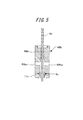
- FIG. 5 is a longitudinal sectional view of a filling head portion 4Br for air blowing connected to the lower end portion of the support portion 4A in place of the filling head portion 4B in the apparatus shown in FIG. 1 prepared separately.
- the filling head portion 4Br is composed of a head tube portion 6Br, a fitting tube piece 5r, and a partition wall member 11r.
- the head tube portion 6Br has a simpler shape than the head tube portion 6B for liquid and penetrates the tube wall.
- an air introduction path 6Bar and a discharge path 6Bbr are provided.
- FIG. 6 shows an outline of a device in which the filling head portion 4Br is connected and fixed to the support portion 4A in FIG. 1 in place of the filling head portion 4B as described above, from the pressurizing device 21r to the valve V2r and the introduction path 6Bar.
- the container can be molded by blowing pressurized air into the preform 31 via the, that is, by air blowing, the preform 31 is expanded in a stretched manner together with the longitudinal stretching by the stretching rod 8.
- the stretching rod 8 is also replaced with a separately prepared stretching rod 8r.
- the pressurization apparatus 21 shown by FIG. 1 can also be utilized in common as the pressurization apparatus 21r.
- the removed filling head portion 4B is moved to an appropriate place, and the steps of disassembly ⁇ cleaning ⁇ reassembly are performed as necessary to prepare for the next production using the liquid as a pressurized medium. be able to.
- cleaning the liquid adhering and remaining by flushing is removed, but since the object to be cleaned is compact and limited to the filling head portion 4B, the number of parts is reduced, and it can be carried out in a separate process, It can be implemented more efficiently.
- FIG. 7 is an explanatory view showing a blow molding apparatus as a comparative example of the blow molding apparatus shown in FIG.
- the apparatus of this comparative example uses liquid as a pressurized medium, similar to the apparatus of FIG. 1, and has substantially the same functions as the apparatus shown in FIG. 1, such as the circulation mechanism of the liquid L, the valve mechanism Vm, and peripheral devices.
- the blow nozzle 4 is an integrated device without being divided into the support portion 4A and the filling head portion 4B.
- the liquid L supplied from the pressurized liquid supply part 22 is supplied in the preform 31 from the introduction path 6a of the supply cylinder part 6 which comprises the blow nozzle 4 via the supply path Fs. Further, the liquid L can be circulated by the circulation path CR through the discharge path 6b.
- this invention is not limited to an above-described Example.
- the setup change in which the pressurized medium is changed from the liquid to the air has been described.
- a configuration in which the liquid is changed to a different kind of liquid may be employed.
- the liquid L is circulated by the circulation path CR.
- an apparatus without this circulation mechanism can be used.
- it was set as the structure which supplies the liquid L to the supply path Fs via the introduction path 6Ba from the pressurized liquid supply part 22, However, About this supply aspect, it can select suitably from various aspects. .
- the valve mechanism Vm can also be appropriately selected from various aspects.
- the stretching rod 8 longitudinal stretching is performed by the stretching rod 8, and then the pressurized liquid L is supplied into the preform 31 with the valve mechanism Vm opened.
- the supply of the pressurized liquid L into the preform 31 can be performed substantially simultaneously with the longitudinal stretching by the stretching rod 8.
- the stretching rod 8 is longitudinally stretched. It is also possible to employ a method in which the container 41 is pulled up to a predetermined height position in the container 41 at an appropriate timing such as immediately before the completion of the shaping of the container 41 with the pressurized liquid L.
- the blow molding apparatus of the present invention can perform changeover to a different type of medium in a short time, and in the field of blow molding using a different type of pressurized liquid from the viewpoint of improving productivity. Is expected to be used widely.
- Mold 2 Cavity 4: Blow nozzle 4A: Support part 4B: Filling head part 5, 5r: Insertion cylinder piece 5a: Circumferential step part 6: Supply cylinder part 6A: Support cylinder part 6Atg, 6tg: Upper rod guide 6B , 6Br: head cylinder portions 6a, 6Ba, 6Bar: introduction passages 6b, 6Bb, 6Bbr: discharge passage 6Bs: seal step portion 6Bc: vent hole 6Bd: reduced diameter portion 7a, 7b: seal member 8, 8r: extending rod 9: Seal body 9a: Shaft body 9t: Seal cylinder piece 9ta: Tapered edge portion 9g: Rod guide 11, 11r: Partition member 12: Support flange 13: Vent hole 14: Seal member 21, 21r: Pressurizing device 22: Pressurization Liquid supply part 23: Liquid circulation part CR: Circulation path Fs: Supply path Hs: Head space L: Liquid Ls: Liquid level P1, P2, P3:
Landscapes
- Engineering & Computer Science (AREA)
- Mechanical Engineering (AREA)
- Manufacturing & Machinery (AREA)
- Blow-Moulding Or Thermoforming Of Plastics Or The Like (AREA)
Abstract
ブロー成形用の金型(1)と、有底筒状のプリフォーム(31)を前記金型(1)に装着した状態で該プリフォーム(31)の口筒部(32)に密に連通するブローノズル(4)と、該ブローノズル(4)の軸方向に挿通する延伸ロッド(8)とを有し、前記プリフォーム(31)の延伸ロッド(8)による縦延伸と、別途配設した加圧液体供給部(22)から前記ブローノズル(4)を介して供給される加圧した液体(L)による膨張状の延伸とにより容器(41)を賦形するブロー成形装置であって、前記ブローノズル(4)は、前記延伸ロッド(8)の姿勢を支持する支持部(4A)と、前記液体(L)のプリフォーム(31)への供給路(Fs)が軸方向に形成され、前記プリフォーム(31)の口筒部(32)に連通する充填ヘッド部(4B)とを有し、該支持部(4A)と充填ヘッド部(4B)を相互に着脱可能に上下方向に連結する構成としたことを特徴とする。
Description
本発明は、加圧媒体として液体を使用する合成樹脂製プリフォームのブロー成形装置に関するものである。
ポリエチレンテレフタレート(PET)樹脂製のブロー成形壜体(所謂、ペットボトル)が、数多くの優れた特性を発揮することから、壜体容器として多方面で使用されている。この種の容器は、有底筒状に射出成形されたプリフォームを、延伸効果を発現させることのできる温度に加熱した状態で、延伸ロッドで縦方向に延伸すると共に加圧したエアを吹き込んで、すなわちエアブローにより膨張状に延伸変形させて成形されるのが一般的である。
一方、特許文献1には加圧媒体としてエアの替わりに液体を使用してプリフォームをブロー成形する方法に係る発明が記載されている。このような成形方法では、液体として、飲料、化粧品、薬品等の最終的に製品に充填される内容液を使用すれば、充填工程を省略することができ生産ラインを簡略化することが可能となる。
図8は加圧媒体としてエアの替わりに液体を使用してプリフォームをブロー成形する、従来のブロー成形装置の概略説明図である。この装置の主部は金型101とブローノズル104を有し、隣接して加圧媒体を供給するための付属設備として加圧液体供給部122と液体循環部を配置している。
加圧液体供給部122はプランジャーポンプ状で、加圧ポンプやコンプレッサー等の加圧装置121から配管P1を介して供給される加圧媒体Fpを動力源として作動し、加圧した液体Lを配管P2、電磁バルブV101を介してブローノズル104内の供給路Fsを経て、ブローノズル104の先端部に口筒部32が密に外嵌するプリフォーム31の内部に供給し、延伸ロッド108による縦延伸と加圧した液体Lによる膨張状の延伸により、プリフォーム31を金型101のキャビティ102の形状に沿って賦形し、容器41を成形する。
ここで、上記のように加圧媒体として液体を使用する装置では、加圧媒体を異種の液体に替える、あるいはエアに替える、所謂、段取り替え時に特にブローノズル104に付着した液体を除去するためのフラッシングに多大な時間を要する。特にブローノズル104は実際には多くの部品から構成されており、分解→フラッシング(洗浄)→再組立て、と云う工程が必要で、次の加圧媒体による生産を開始するのに長時間を要し生産性が低下してしまうと云う問題がある。
そこで本発明は、加圧媒体として液体を使用するブロー成形装置において、異種の媒体への段取り替えを短時間に実施できるようにすることを技術的課題とし、複数の加圧媒体による成形を高い生産性で実施できるブロー成形装置を提供することを目的とするものである。
上記課題を解決するための本発明の主たる構成は、ブロー成形用の金型と、有底筒状のプリフォームを金型に装着した状態でプリフォームの口筒部に密に連通するブローノズルと、このブローノズルの軸方向に挿通する延伸ロッドとを有し、プリフォームの延伸ロッドによる縦延伸と、別途配設した加圧液体供給部からブローノズルを介して供給される加圧した液体による膨張状の延伸とにより容器を賦形するブロー成形装置であって、ブローノズルは、延伸ロッドの姿勢を支持する支持部と、液体のプリフォームへの供給路が軸方向に形成されプリフォームの口筒部に連通する充填ヘッド部とを有し、これら支持部と充填ヘッド部を相互に着脱可能に上下方向に連結する構成とする、と云うものである。
上記構成は、多くの部品から構成されるブローノズルを上下方向に、加圧媒体である液体が触れない部分である延伸ロッドの姿勢を支持する支持部と、液体の供給路が形成され液体が付着、残留する充填ヘッド部とに分割し、充填ヘッド部を、謂わば、交換可能なカートリッジタイプとすることにより、異種媒体への段取り替え時には、これまで使用してきた充填ヘッド部を取り外し、別途用意した異種媒体用の充填ヘッド部と取り替えて次の異種媒体によるブロー成形を短時間でスタートすることができる。
そして、取り外した充填ヘッド部は必要に応じて分解→洗浄→再組立て、をして次の生産に備えておくことができるが、この洗浄についても、支持部と充填ヘッド部が一体となった従来の装置に比較して、洗浄の対象がコンパクトで、また充填ヘッド部に限定されるので、部品点数も減り、別工程で実施できることも相俟って、より効率的に洗浄をすることが可能となる。さらに、液体の流動性、整流性、プリフォームへの充填性を損なわない範囲で充填ヘッド部に形成される供給路を短く、またシンプルに構成することにより、液体の接触面積や、液体の滞留部分を少なくすることができ、充填ヘッド部の洗浄に要する時間をより短縮化することができる。
上記課題を解決するための本発明の他の構成は、上記主たる構成において、充填ヘッド部の供給路の下流側端部にこの供給路の開閉が可能にバルブ機構を配設し、バルブ機構の閉状態で供給路と加圧液体供給部で液体の循環が可能に、また開状態で供給路を経てプリフォーム内への加圧した液体の供給が可能に構成する、と云うものである。
上記構成の装置によれば、プリフォームを金型へセットする工程から成形した容器を金型から取り外す工程に至るブロー成形の全工程のうち、加圧した液体を、供給路を経てプリフォームの内部に供給し容器を賦形する工程を除いた他の工程で、加圧媒体として使用する液体を常時、あるいは必要に応じて供給路と加圧液体供給部との間で循環させて所定の温度に調整することができ、プリフォーム内に供給する液体の温度を高い精度で制御することでき、容器の賦形を一定の温度条件で安定して達成することができる。
ここで、上記構成のような液体の循環機構を付設する構成では、バブル機構を配設したり、供給路と加圧液体供給部で循環路を配設したりする必要があり、ブローノズルの部品点数がさらに増加すると共に、内部構造が複雑になるため、洗浄により時間を要する。従ってこのような循環機能を付設した装置では、前述した主たる構成の、充填ヘッド部を取り替えカートリッジタイプとすることによる作用効果が極めて効果的に発揮される。
上記課題を解決するための本発明のさらに他の構成は、上記循環機能を付設した構成において、加圧液体供給部に所定の温度に調整して液体を供給する液体循環部を配設し、供給路は、この供給路の上流側端部に配設される導入路を介して加圧液体供給部と開閉可能に連通し、下流側でバルブ機構の上流側位置に配設される排出路を介して開閉可能に液体循環部に連通するものとし、バルブ機構の閉状態で、液体循環部を介して、供給路と加圧液体供給部の間で液体の循環が可能に構成する、と云うものであり、供給路と加圧液体供給部の間で液体を循環するための構成に関するものである。
上記課題を解決するための本発明のさらに他の構成は、上記主たる構成において、筒棒状の軸体に摺動可能に延伸ロッドを挿通して棒状のシール体とし、このシール体をブローノズルの軸方向に移動可能に挿通、配設し、このシール体の先端部の、充填ヘッド部の内周面に配設したシール段部への当接により供給路を閉状態とすることが可能に構成し、このシール体の先端部のシール段部への当接と脱当接によりバルブ機構を構成する、と云うものである。
上記構成は、充填ヘッド部内の供給路の開閉をするバルブ機構に関するものであり、ブローノズルの軸方向に移動可能に挿通、配設した棒状のシール体の移動動作により、供給路を容易に開閉することができる。また、加圧液体として飲料、化粧品、薬品等の、最終的に製品に充填される液体を使用し、これら液体を最終的に充填した製品を製造する場合には、成形と同時に、内容液が充填された容器におけるヘッドスペースを所定の量に高精度に制御する必要があるが、上記構成では、液体の供給を停止するためのバルブ機構が充填ヘッド部内に配設されているので、このバルブ機構をプリフォームの口筒部の直上にも配設することもでき、バルブ機構直下からプリフォームの口筒部の上端にかけての供給路部分に残留する液の量を少なくして液体を高精度で計量することができ、ヘッドスペースをより高精度に制御することが可能となる。
上記課題を解決するための本発明のさらに他の構成は、上記主たる構成において、液体用の充填ヘッド部と交換して、別途用意したエアブロー用の充填ヘッド部を支持部に連結し、エアブローによるプリフォームの膨張状の延伸を実施可能に構成すると云うものである。
上記課題を解決するための本発明のさらに他の構成は、上記主たる構成において、液体用の充填ヘッド部と交換して、別途用意したもう一つの加圧した液体用の充填ヘッド部を支持部に連結し、先に使用した液体とは異種の加圧した液体によるプリフォームの膨張状の延伸を実施可能に構成すると云うものである。
本発明のブロー成形装置は、上記した構成となっており、本発明の主たる構成を有する装置によれば、多くの部品から構成されるブローノズルを上下方向に、加圧媒体である液体が触れない部分である延伸ロッドの姿勢を支持する支持部と、液体の供給路が形成され液体が付着、残留する充填ヘッド部に分割し、充填ヘッド部を、謂わば、カートリッジタイプとすることにより、異種の媒体への段取り替えを短時間に実施でき、複数の加圧媒体による成形を高い生産性で実施できる成形ブロー成形装置を提供することができる。
また、取り外した充填ヘッド部は必要に応じて分解→洗浄→再組立て、をして次の生産に備えておくことができるが、この洗浄についても、支持部と充填ヘッド部が一体となった従来の装置に比較し、洗浄の対象がコンパクトで、また充填ヘッド部に限定されるので、部品点数も減り、別工程で実施できることも相俟って、より効率的に洗浄をすることができる。
以下、本発明の実施形態を実施例に沿って図面を参照しながら説明する。図1~4は本発明のブロー成形装置の一実施例、さらにはこの装置を使用したブロー成形方法を説明するためのものである。まず、図1と図2を参照しながら装置の全体的な構成を説明するが、図1は本発明のブロー成形装置の全体的な構成を示す説明図であり、図2は図1中、縦断面で示される装置の主部の充填ヘッド部4B近傍を拡大した断面図で、細かい構成部位については図2を参照する。
図1、2は、金型1にプリフォーム31を装着し、ブローノズル4の先端をこのプリフォーム31の口筒部32に嵌入した状態を示している。使用するプリフォーム31の形状は有底円筒の試験管状で、上端部に口筒部32を起立設し、この口筒部32の下端部にはネックリング33が配設されており、口筒部32を外部に(図1、2中では上方に)突出させた状態で金型1内に装着されている。
この装置の主部は金型1、ブローノズル4を有し、付属設備として加圧装置21、加圧液体供給部22、液体循環部23を配置している。ブローノズル4は全体として筒状で、後述するシール体9や延伸ロッド8の姿勢を支持する支持部4Aと、液体Lのプリフォーム31への供給路Fsが軸方向に形成され、その下端部がプリフォーム31の口筒部32に連通する充填ヘッド部4Bから構成されており、この支持部4Aと充填ヘッド部4Bは、相互に着脱可能にシール部材14により液密状に、上下方向に連結されており、本実施例では支持部4Aの下端部が充填ヘッド部4Bの上端部に嵌入するようにして螺合により両者が着脱可能に連結固定している。
支持部4Aは中心軸方向に沿ってシール体9や延伸ロッド8が挿通する支持筒部6Aと、この支持筒部6Aの上部に配設され延伸ロッド8のガイドとしての機能を発揮する上部ロッドガイド6Atgを有する。
一方、充填ヘッド部4Bは、内部に供給路Fsを形成したヘッド筒部6Bと、このヘッド筒部6Bにシール部材(Oリング)7bを介して密に連結される嵌入筒片5と、隔壁部材11から構成されている。嵌入筒片5は、図2に示されるように外周壁には先端に向かって縮径する周段部5aが周設されており、円筒状の先端部がプリフォーム31の口筒部32に嵌入し、周段部5aと口筒部32の上端面のシール部材(Oリング)7aを介した当接により、充填ヘッド部4Bと口筒部32が密に連通状に連結するようにしている。
隔壁部材11は、図2に示されるように金型1の上方に突出したプリフォーム31の口筒部32の外周面を、空間Sを介して囲繞するように金型1の上方に配設される。また、隔壁部材11には必要に応じて空間Sに加圧気体を供給するための通気孔13が配設されている。また隔壁部材11の下端部に周設した支持鍔片12をプリフォーム31のネックリング33に上方から当接させて、プリフォーム31の装着姿勢を保持するようにしている。
ヘッド筒部6Bは全体として円柱状の中空部を有する筒状の部材で、図1、2に示されるように、上端部に周壁を貫通して液体Lの導入路6Baが配設されており、下方には同じく周壁を貫通して液体Lの排出路6Bbが配設されている。また、この排出路6Bbのさらに下方、このヘッド筒部6Bの下端部の内周面には下方に向かって縮径状に傾斜したシール段部6Bsが周設されており、このシール段部6Bsの直下には縮径部6Bdが配設されている。また、このシール段部6Bsの下にはこのヘッド筒部6Bの外部と内部を連通するための通気孔6Bcが配設されている。
また、上記のように支持部4Aと充填ヘッド部4Bから構成されるブローノズル4の中には、軸方向(図1中では上下方向)に細長い棒状のシール体9が挿通、配設されている。このシール体9は、下端部に短円筒状のシール筒片9tが同軸心状に嵌合組み付きして構成される細長い円筒棒状の金属性の軸体9aとシール筒片9tの下端に同軸心状に連結する短円筒状でポリエーテルエーテルケトン(PEEK)樹脂製のロッドガイド9gに、円柱状の延伸ロッド8を挿通したものである。ここで、耐摩耗性や滑り性等の観点から、延伸ロッド8は若干の隙間を介して軸体9aに挿通しており、一方、ロッドガイド9gには延伸ロッド8が摺動可能に周接状に挿通する構成としている。
なお、延伸ロッド8は支持部4Aを構成する支持筒部6Aの上端部で上部ロッドガイド6Atgに摺動可能に周接状に挿通している(図1参照)。また、シール筒片9tの下端面の外周縁部は角取りしてテーパー縁部9taとなっている。また、ロッドガイド9gは充填ヘッド部4Bの縮径部6Bdへの摺動状の嵌入、脱嵌入が可能に配設されている。
そして、充填ヘッド部4Bとシール体9により充填ヘッド部4B内に、この充填ヘッド部4Bの軸方向に沿って、プリフォーム31内に連通する円筒状の供給路Fsが形成され、シール体9を下降させることにより図1、2に示されるようにシール筒片9tのテーパー縁部9taがヘッド筒部6Bの下端部の内周面に周設されるシール段部6Bsに当接して供給路Fsのプリフォーム31内部への連通を閉状態とすることができ、またシール体9を図3に示されるように上昇させることにより開状態とすることができ、このテーパー縁部9taのシール段部6Bsへの当接と、脱当接によりバルブ機構Vmが構成される。
また、バルブ機構Vmの閉状態では、ロッドガイド9gが、ヘッド筒部6Bのシール段部6Bs直下の縮径部6Bdに嵌入した状態となり、バルブ機構Vmの開状態では、ロッドガイド9gが縮径部6Bdから上方に脱嵌入した状態となり、液体Lの流路が開放される。
次に、付属設備についてみると、加圧装置21は、従来からブロー成形では必須の設備であり、加圧ポンプやコンプレッサー等の大型の設備であり、この加圧装置21から配管P1を介して供給される加圧流体Fpが、加圧した液体Lを供給するプランジャーポンプ状の加圧液体供給部22を駆動するための動力源となる。また、加圧液体供給部22には、図示したプランジャー等ポンプ状のものの他にも2部屋を有するピストン内蔵のシリンダー等のものを使用することができる。
また、本実施例の装置では液体循環部23を配設し、液体Lを配管R1から新たに補給しながら所定の温度に調整して配管R2により加圧液体供給部22に供給すると共に、液体Lを、所定の温度に調整しながら加圧液体供給部22と充填ヘッド部4B内の供給路Fsとの間を循環させる循環機能を付設している。すなわち、図1に示される状態のようにバルブ機構Vmが閉状態にある際には、必要に応じて、液体Lを供給路Fs→排出路6Bb→配管R3→液体循環部23→配管R2→加圧液体供給部22→配管P2→導入路6Ba→供給路Fsと云うように構成される循環路CRを循環させることができる構成としている。そして、このような循環機能を付設することにより、プリフォーム31内に供給する液体Lの温度を高い精度で制御することができ、成形される容器41の品質を安定化し、生産性を高めることができる。
次に、図1~図4を参照しながら、上記説明したブロー成形装置を使用した合成樹脂製容器のブロー成形の工程の一例について説明する。ブロー成形は次の(1)~(7)に記載した工程を順次、実施する。
(1)まず、口筒部32を除く部分をブロー成形に適した温度に加熱したプリフォーム31を、口筒部32を上方に突出させた状態でブロー成形用の金型1に装着し、型締めする。
(2)次に、支持部4Aと充填ヘッド部4Bを連結固定したブローノズル4を口筒部32の上方から下降させ、嵌入筒片5の先端部を口筒部32に嵌入し図1、2に示す状態とする。ここで、シール体9の下端部を構成するシール筒片9tのテーパー縁部9taはヘッド筒部6Bのシール段部6Bsに当接しており、バルブ機構Vmが閉状態となっており、また延伸ロッド8がプリフォーム31内に挿入した状態となっている。また、バルブV1、V2、V3はいずれも開状態とし、液体Lは、液体循環部23で温度調整されながら前述した循環路CRを循環している。
(3)次に、図2中、二点鎖線で示したように延伸ロッド8によりプリフォーム31を縦延伸する。この縦延伸工程では、延伸ロッド8の姿勢は、支持筒部6Aの上部に位置する上部ロッドガイド6Atgとヘッド筒部6Bの縮径部6Bdに支持されたロッドガイド9gによりしっかりと支持されており、プリフォーム31の縦延伸を、芯ブレおよび芯ズレのない状態で安定して実施することができる。ここで、本実施例では延伸ロッド8によりプリフォーム31の底壁が金型1の底壁に当接するまで縦延伸する構成としているが、ブロー成形の生産性や、成形される容器41の肉厚分布等を考慮して途中の高さまで縦延伸する構成とすることもできる。
(4)次に、図2の縦延伸した状態から、図3に示されるように軸体9aを上昇させてバルブ機構Vmを開状態とし、バルブV1、V3を閉状態として循環路CRに沿った液体Lの循環を停止し、加圧液体供給部22から供給される加圧した液体Lを、充填ヘッド部4B内の供給路Fsを介して口筒部32からプリフォーム31内に供給して金型1のキャビティ2の形状に沿って膨張状に延伸して容器41を賦形する。なお、この工程で、液体Lの圧力により口筒部32が拡径変形するような場合には、配管P3を介して隔壁部材11に配設した通気孔13から加圧気体を隔壁部材11内に導入し、口筒部32の外周面を囲繞する空間Sを加圧することにより、このような拡径変形を効果的に抑制することができる。
(5)次に、上記のように容器41が賦形された後に、図4に示されるように軸体9aを下降させてバルブ機構Vmを閉状態とし、バルブV1、V2、V3を開状態として、液体Lを再び循環路CRに沿って循環させる。
(6)そして(5)の工程と同時に、あるいは少し遅れて、図4に示されるように延伸ロッド8の先端部を容器41内から脱挿入する。ここで、延伸ロッド8の先端部の脱挿入に伴って、バルブ機構Vmより下方の供給路Fsに残存する液体Lは全て容器41内に流入し、さらに容器41内で液面Lsが下降し、図4に示されるように予め設定した所定のヘッドスペースHsに調整することができる。なお、延伸ロッド8の先端部の脱挿入動作の際に、容器41内が減圧状態になり容器41が減容状に変形する場合には、充填ヘッド部4Bのヘッド筒部6Bに配設した通気孔6BcをバルブV4により開状態とすることにより、容器41内の減圧状態を緩和することができ、上記のような容器41の変形を効果的に防ぐことができる。
ここで、本実施例の上記構成では、液体Lの供給を停止するためのバルブ機構Vmが充填ヘッド部4Bの下端部近傍に配設されているので、このバルブ機構Vmが配設されている位置からプリフォーム31の口筒部32の上端にかけての供給路Fs部分に残留する液体Lの量を少なくして高精度で計量することができ、ヘッドスペースHsをより高精度に制御することが可能となる。
(7)そして、図示は省略しているが容器41の口筒部32を嵌入筒片5から脱嵌合し、さらに金型1を型開きして液体Lが充填した容器41を取り出し、口筒部32をキャップでシールし、製品とする。
次に、上記のように加圧媒体として液体Lを使用するブロー成形装置で、加圧媒体を異種の流体に替えてブロー成形をする際の段取り替えの一例、ここでは加圧媒体を液体からエアに替える際の段取り替えの例について説明する。図5は、別途用意した図1に示される装置中の充填ヘッド部4Bに替えて支持部4Aの下端部に連結するエアブロー用の充填ヘッド部4Brの縦断面図である。この充填ヘッド部4Brはヘッド筒部6Brと嵌入筒片5rと隔壁部材11rから構成されており、ヘッド筒部6Brは液体用のヘッド筒部6Bに比較してシンプルな形状で、筒壁を貫通してエアの導入路6Barと排出路6Bbrが配設されている。
段取り替えの際には、図1に示した装置において、支持部4Aから充填ヘッド部4Bを螺脱して取り外し、替わりに上記のエアブロー用の充填ヘッド部4Brを支持部4Aの下端部に螺合により連結固定する。図6は上記のように図1中の支持部4Aに充填ヘッド部4Bの替わりに充填ヘッド部4Brを連結固定した装置の概要を示すものであり、加圧装置21rからバルブV2r、導入路6Barを介して、プリフォーム31に加圧したエアを吹き込んで、すなわちエアブローにより、延伸ロッド8による縦延伸と共にプリフォーム31を延伸状に膨張させて容器を成形することができる。なお、延伸ロッド8も別途準備した延伸ロッド8rに交換している。また、加圧装置21rとして図1に示される加圧装置21を共通的に利用することもできる。
一方、取り外した充填ヘッド部4Bについては、適宜の場所に移動させて、必要に応じて分解→洗浄→再組立て、の工程を実施し、液体を加圧媒体とする次の生産に備えておくことができる。洗浄にあたっては、フラッシングにより付着、残留した液体を除去するが、洗浄の対象がコンパクトで、また充填ヘッド部4Bに限定されるので、部品点数も減り、別工程で実施できることも相俟って、より効率的に実施することができる。
ここで、図7は図1に示すブロー成形装置の比較例となるブロー成形装置を示す説明図である。この比較例の装置は図1の装置と同様、液体を加圧媒体として使用するもので、液体Lの循環機構、バルブ機構Vm、周辺装置等、図1に示す装置と略同様な機能を有するものであるが、ブローノズル4を支持部4Aと充填ヘッド部4Bに分割することなく、一体とした装置である。そして加圧液体供給部22から供給される液体Lは、ブローノズル4を構成する供給筒部6の導入路6aから供給路Fsを経てプリフォーム31内に供給される。また液体Lを、排出路6bを経て循環路CRにより循環させることができる。
但し、この比較例の装置を利用して、前述したようにエアブローによるブロー成形を実施しようとすると、段取り替え時に、特にブローノズル4の内部に付着した液体を除去するため、分解→洗浄→再組立て、と云う工程に多大な時間を要し、エアブローによる生産を開始するのに長時間を要し生産性が低下してしまう。
なお、図1の実施例の装置と、図7の比較例の装置を比較すると分かるように、図1の装置ではブローノズル4を支持部4Aと充填ヘッド部4Bに分割するにあたって、液体Lの流動性、整流性、プリフォーム31への充填性を損なわない範囲で充填ヘッド部4Bに形成される供給路Fsを可能な範囲で短くして、充填ヘッド部4Bを短くしコンパクトな構成としている。そしてこのように、充填ヘッド部4Bをコンパクト化することにより、充填ヘッド部4Bの交換作業が容易になり、また分解→洗浄→再組立の作業をより簡便にすることができる。
以上、実施例に沿って本発明のブロー成形装置の実施形態について説明したが、本発明は上記した実施例に限定されるものではない。上記実施例では、加圧媒体を液体からエアに替える段取り替えについて説明したが、液体から異種の液体に替える構成とすることもできる。また、上記実施例の装置では液体Lを循環路CRにより循環させる構成としたが、この循環機構のない装置とすることもできる。また、上記実施例では加圧液体供給部22から導入路6Baを介して供給路Fsへ液体Lを供給する構成としたが、この供給態様についても様々な態様の中から適宜選択することができる。バルブ機構Vmについても様々な態様の中から適宜選択することができる。
また、本発明の装置を使用したブロー成形の工程の例では、まず延伸ロッド8による縦延伸を実施し、その後にバルブ機構Vmを開状態として加圧した液体Lをプリフォーム31内に供給するものとしたが、加圧した液体Lのプリフォーム31内への供給を延伸ロッド8による縦延伸と略同時に実施することもできる。また、ヘッドスペースHsの調整や、生産性を含めたブロー成形性、減容変形の有無、成形した容器41における残留歪みの有無、周壁の均一性等を考慮して、延伸ロッド8を縦延伸が終了した位置から、加圧した液体Lによる容器41の賦形が完了する直前等の適宜のタイミングで容器41内の所定の高さ位置まで引き上げておく方法を採用することもできる。
以上説明したように、本発明のブロー成形装置は異種の媒体への段取り替えを短時間に実施できるものであり、生産性の向上の観点から異種の加圧液体を使用するブロー成形の分野での幅広い利用展開が期待される。
1 :金型
2 :キャビティ
4 :ブローノズル
4A:支持部
4B:充填ヘッド部
5、5r:嵌入筒片
5a:周段部
6 :供給筒部
6A:支持筒部
6Atg、6tg:上部ロッドガイド
6B、6Br:ヘッド筒部
6a、6Ba、6Bar:導入路
6b、6Bb、6Bbr:排出路
6Bs:シール段部
6Bc:通気孔
6Bd:縮径部
7a、7b:シール部材
8、8r:延伸ロッド
9 :シール体
9a:軸体
9t:シール筒片
9ta:テーパー縁部
9g:ロッドガイド
11、11r:隔壁部材
12:支持鍔片
13:通気孔
14:シール部材
21、21r:加圧装置
22:加圧液体供給部
23:液体循環部
CR:循環路
Fs:供給路
Hs:ヘッドスペース
L :液体
Ls:液面
P1、P2、P3:配管
R1、R2:配管
S :空間
V1、V2、V2r、V3、V3r、V4:バルブ
Vm:バルブ機構
31:プリフォーム
32:口筒部
33:ネックリング
41:容器
101:金型
102:キャビティ
104:ブローノズル
108:ロッド
121:加圧装置
122:加圧液体供給部
V101:バルブ
Claims (6)
- ブロー成形用の金型(1)と、有底筒状のプリフォーム(31)を前記金型(1)に装着した状態で該プリフォーム(31)の口筒部(32)に密に連通するブローノズル(4)と、該ブローノズル(4)の軸方向に挿通する延伸ロッド(8)とを有し、前記プリフォーム(31)の延伸ロッド(8)による縦延伸と、別途配設した加圧液体供給部(22)から前記ブローノズル(4)を介して供給される加圧した液体(L)による膨張状の延伸とにより容器(41)を賦形するブロー成形装置であって、
前記ブローノズル(4)は、前記延伸ロッド(8)の姿勢を支持する支持部(4A)と、前記液体(L)のプリフォーム(31)への供給路(Fs)が軸方向に形成され、前記プリフォーム(31)の口筒部(32)に連通する充填ヘッド部(4B)とを有し、
該支持部(4A)と充填ヘッド部(4B)を相互に着脱可能に上下方向に連結する構成としたことを特徴とするブロー成形装置。 - 充填ヘッド部(4B)において、供給路(Fs)の下流側端部に該供給路(Fs)の開閉が可能にバルブ機構(Vm)を配設し、前記バルブ機構(Vm)の閉状態で供給路(Fs)と加圧液体供給部(22)で液体(L)の循環が可能に、また開状態で供給路(Fs)を経てプリフォーム(31)内への加圧した液体(L)の供給が可能に構成した請求項1記載のブロー成形装置。
- 加圧液体供給部(22)に所定の温度に調整して液体(L)を供給する液体循環部(23)を配設し、供給路(Fs)は、充填ヘッド部(4B)の該供給路(Fs)の上流側端部に配設される導入路(6Ba)を介して加圧液体供給部(22)と開閉可能に連通し、下流側でバルブ機構(Vm)の上流側位置に配設される排出路(6Bb)を介して開閉可能に前記液体循環部(23)に連通するものとし、前記バルブ機構(Vm)の閉状態で、前記液体循環部(23)を介して、供給路(Fs)と加圧液体供給部(22)の間で液体(L)の循環が可能に構成した請求項2記載のブロー成形装置。
- 筒棒状の軸体(9a)に摺動可能に延伸ロッド(8)を挿通して棒状のシール体(9)とし、該シール体(9)をブローノズル(4)の軸方向に移動可能に挿通、配設し、該シール体(9)の先端部の、充填ヘッド部(4B)の内周面に配設したシール段部(6Bs)への当接により供給路(Fs)を閉状態とすることが可能に構成し、該シール体(9)の先端部のシール段部(6Bs)への当接と脱当接によりバルブ機構(Vm)を構成した請求項1に記載のブロー成形装置。
- 液体(L)用の充填ヘッド部(4B)と交換して、別途用意したエアブロー用の充填ヘッド部(4Br)を支持部(4A)に連結し、エアブローによるプリフォーム(31)の膨張状の延伸を実施可能に構成した請求項1に記載のブロー成形装置。
- 液体(L)用の充填ヘッド部(4B)と交換して、別途用意したもう一つの加圧した液体(L)用の充填ヘッド部(4B)を支持部(4A)に連結し、先に使用した液体(L)とは異種の加圧した液体(L)によるプリフォーム(31)の膨張状の延伸を実施可能に構成した請求項1に記載のブロー成形装置。
Priority Applications (3)
| Application Number | Priority Date | Filing Date | Title |
|---|---|---|---|
| CN201380068200.4A CN104870165B (zh) | 2012-12-28 | 2013-12-04 | 吹塑成型装置 |
| US14/758,394 US9579841B2 (en) | 2012-12-28 | 2013-12-04 | Blow molding device |
| EP13867189.6A EP2939815B1 (en) | 2012-12-28 | 2013-12-04 | Blow-molding device |
Applications Claiming Priority (2)
| Application Number | Priority Date | Filing Date | Title |
|---|---|---|---|
| JP2012-287493 | 2012-12-28 | ||
| JP2012287493A JP5808733B2 (ja) | 2012-12-28 | 2012-12-28 | ブロー成形装置 |
Publications (1)
| Publication Number | Publication Date |
|---|---|
| WO2014103188A1 true WO2014103188A1 (ja) | 2014-07-03 |
Family
ID=51020312
Family Applications (1)
| Application Number | Title | Priority Date | Filing Date |
|---|---|---|---|
| PCT/JP2013/007133 WO2014103188A1 (ja) | 2012-12-28 | 2013-12-04 | ブロー成形装置 |
Country Status (5)
| Country | Link |
|---|---|
| US (1) | US9579841B2 (ja) |
| EP (1) | EP2939815B1 (ja) |
| JP (1) | JP5808733B2 (ja) |
| CN (1) | CN104870165B (ja) |
| WO (1) | WO2014103188A1 (ja) |
Cited By (6)
| Publication number | Priority date | Publication date | Assignee | Title |
|---|---|---|---|---|
| EP2810763A4 (en) * | 2012-01-31 | 2015-10-28 | Discma Ag | blow molding |
| EP2987606A1 (de) * | 2014-08-20 | 2016-02-24 | Krones AG | Verfahren zum Ausformen und Füllen von Behältern und Formfüllmaschine |
| EP2987732A1 (de) * | 2014-08-20 | 2016-02-24 | Krones AG | Formfüllmaschine |
| EP2987622A1 (de) * | 2014-08-20 | 2016-02-24 | Krones AG | Formfüllmaschine und Verfahren zum Ausformen und Füllen von Behältern |
| CN107635745A (zh) * | 2015-04-30 | 2018-01-26 | 帝斯克玛股份有限公司 | 液体吹塑成型装置 |
| CN107708964A (zh) * | 2015-03-31 | 2018-02-16 | 帝斯克玛股份有限公司 | 液体吹塑成型装置 |
Families Citing this family (22)
| Publication number | Priority date | Publication date | Assignee | Title |
|---|---|---|---|---|
| EP2821204B1 (en) * | 2013-07-02 | 2017-12-27 | Discma AG | Container-fabricating apparatus and a method for the cleaning thereof |
| JP6356556B2 (ja) | 2014-09-24 | 2018-07-11 | 株式会社吉野工業所 | ブロー成形装置 |
| JP6450590B2 (ja) * | 2014-12-26 | 2019-01-09 | 株式会社吉野工業所 | 液体ブロー成形装置 |
| JP6450616B2 (ja) * | 2015-03-13 | 2019-01-09 | 株式会社吉野工業所 | ブロー成形装置 |
| EP3269530B1 (en) | 2015-03-13 | 2019-12-04 | Discma AG | Blow molding device |
| JP6401086B2 (ja) * | 2015-03-13 | 2018-10-03 | 株式会社吉野工業所 | ブロー成形装置 |
| JP6450617B2 (ja) * | 2015-03-13 | 2019-01-09 | 株式会社吉野工業所 | ブロー成形装置 |
| US10315408B2 (en) * | 2015-04-28 | 2019-06-11 | General Electric Company | Additive manufacturing apparatus and method |
| DE102015007690A1 (de) * | 2015-06-11 | 2016-12-15 | Kocher-Plastik Maschinenbau Gmbh | Verfahren zum Herstellen eines befüllten und geschlossenen Behälters sowie Vorrichtung zum Durchführen des Verfahrens und ein danach hergestellter Behälter |
| CN105172107B (zh) * | 2015-10-08 | 2018-02-27 | 湖南科伦制药有限公司 | 一种吹瓶机及吹瓶方法 |
| EP3370945B1 (en) * | 2015-11-03 | 2019-11-13 | Discma AG | Forming head with integrated seal pin/stretch rod and various sealing gometries |
| CN108430736A (zh) * | 2015-11-16 | 2018-08-21 | 帝斯克玛股份有限公司 | 喷嘴活塞及操作所述喷嘴活塞的方法 |
| JP6629647B2 (ja) * | 2016-03-11 | 2020-01-15 | 株式会社吉野工業所 | 液体ブロー成形装置及び液体ブロー成形方法 |
| JP6594823B2 (ja) * | 2016-04-28 | 2019-10-23 | 株式会社吉野工業所 | 液体ブロー成形方法 |
| JP6654110B2 (ja) | 2016-06-30 | 2020-02-26 | 株式会社吉野工業所 | 液体ブロー成形装置 |
| MX2019012314A (es) * | 2017-04-26 | 2019-11-28 | Amcor Rigid Plastics Usa Llc | Modulo portatil para sistema de formacion y llenado de envases. |
| EP3685985B1 (en) * | 2017-09-20 | 2022-01-26 | Yoshino Kogyosho Co., Ltd. | Liquid-containing container manufacturing method |
| DE102018106779A1 (de) * | 2018-03-22 | 2019-09-26 | Krones Ag | Vorrichtung zum Expandieren von Kunststoffbehältnissen mit Absperrventil zwischen Druckerzeugungseinrichtung und Einfülleinrichtung |
| DE102018106932A1 (de) * | 2018-03-23 | 2019-09-26 | Krones Aktiengesellschaft | Vorrichtung zum Expandieren von Kunststoffbehältnissen mit doppelt wirkender Druckerzeugungseinrichtung |
| EP3784465B1 (en) * | 2018-04-25 | 2023-03-29 | LiquiForm Group LLC | Nozzle shaft assembly |
| JP7482333B2 (ja) * | 2021-09-08 | 2024-05-13 | 八千代工業株式会社 | 燃料タンク |
| DE102022119880B3 (de) * | 2022-08-08 | 2023-06-01 | Khs Gmbh | Vorrichtung und Verwendung einer Vorrichtung sowie Anlage und Verfahren zum Herstellen eines mit flüssigem Füllgut befüllten Behälters aus einem thermisch konditionierten Vorformling |
Citations (4)
| Publication number | Priority date | Publication date | Assignee | Title |
|---|---|---|---|---|
| JPH11138619A (ja) * | 1997-11-07 | 1999-05-25 | Hokkai Can Co Ltd | 合成樹脂製ボトルの製造装置 |
| JP2000043129A (ja) | 1998-07-29 | 2000-02-15 | Ishikawajima Harima Heavy Ind Co Ltd | プラスチック容器の成形方法 |
| WO2012051368A2 (en) * | 2010-10-15 | 2012-04-19 | Amcor Limited | Blow nozzle to control liquid flow with pre-stretch rod assembly |
| JP2013132861A (ja) * | 2011-12-27 | 2013-07-08 | Yoshino Kogyosho Co Ltd | 2軸延伸ブロー成形装置及び容器の製造方法 |
Family Cites Families (11)
| Publication number | Priority date | Publication date | Assignee | Title |
|---|---|---|---|---|
| US4552527A (en) * | 1984-10-09 | 1985-11-12 | Sewell Plastics, Inc. | Nozzle assembly |
| US5474735A (en) * | 1993-09-24 | 1995-12-12 | Continental Pet Technologies, Inc. | Pulse blow method for forming container with enhanced thermal stability |
| FR2848905B1 (fr) * | 2002-12-19 | 2006-07-28 | Sidel Sa | Installation de soufflage a tuyere-cloche |
| ATE423670T1 (de) * | 2003-11-06 | 2009-03-15 | Nestle Waters Man & Technology | Herstellungsverfahren von behältern aus polyesterharz |
| FR2909028B1 (fr) * | 2006-11-28 | 2009-02-13 | Sidel Participations | Installation de soufflage de corps creux. |
| DE102007032434B4 (de) * | 2007-07-10 | 2019-08-22 | Krones Aktiengesellschaft | Blasvorrichtung zum Expandieren von Behältnissen |
| US8017064B2 (en) * | 2007-12-06 | 2011-09-13 | Amcor Limited | Liquid or hydraulic blow molding |
| EP2143542A1 (fr) | 2008-07-07 | 2010-01-13 | Nestec S.A. | Procédé et dispositif de conditionnement d'un liquide alimentaire |
| US10696434B2 (en) | 2011-01-31 | 2020-06-30 | Khs Gmbh | Method and device for producing containers which are filled with a liquid filling substance |
| BR112013021068B1 (pt) * | 2011-02-16 | 2021-09-14 | Amcor Limited | Bocal de sopro para controlar o fluxo de líquido com montagem de haste de pré- estiramento e pino de vedação de assentamento metálico |
| EP2810763B1 (en) * | 2012-01-31 | 2018-03-07 | Discma AG | Blow molding device |
-
2012
- 2012-12-28 JP JP2012287493A patent/JP5808733B2/ja active Active
-
2013
- 2013-12-04 CN CN201380068200.4A patent/CN104870165B/zh active Active
- 2013-12-04 EP EP13867189.6A patent/EP2939815B1/en active Active
- 2013-12-04 WO PCT/JP2013/007133 patent/WO2014103188A1/ja active Application Filing
- 2013-12-04 US US14/758,394 patent/US9579841B2/en active Active
Patent Citations (4)
| Publication number | Priority date | Publication date | Assignee | Title |
|---|---|---|---|---|
| JPH11138619A (ja) * | 1997-11-07 | 1999-05-25 | Hokkai Can Co Ltd | 合成樹脂製ボトルの製造装置 |
| JP2000043129A (ja) | 1998-07-29 | 2000-02-15 | Ishikawajima Harima Heavy Ind Co Ltd | プラスチック容器の成形方法 |
| WO2012051368A2 (en) * | 2010-10-15 | 2012-04-19 | Amcor Limited | Blow nozzle to control liquid flow with pre-stretch rod assembly |
| JP2013132861A (ja) * | 2011-12-27 | 2013-07-08 | Yoshino Kogyosho Co Ltd | 2軸延伸ブロー成形装置及び容器の製造方法 |
Non-Patent Citations (1)
| Title |
|---|
| See also references of EP2939815A4 |
Cited By (9)
| Publication number | Priority date | Publication date | Assignee | Title |
|---|---|---|---|---|
| EP2810763A4 (en) * | 2012-01-31 | 2015-10-28 | Discma Ag | blow molding |
| EP2987606A1 (de) * | 2014-08-20 | 2016-02-24 | Krones AG | Verfahren zum Ausformen und Füllen von Behältern und Formfüllmaschine |
| EP2987732A1 (de) * | 2014-08-20 | 2016-02-24 | Krones AG | Formfüllmaschine |
| EP2987622A1 (de) * | 2014-08-20 | 2016-02-24 | Krones AG | Formfüllmaschine und Verfahren zum Ausformen und Füllen von Behältern |
| CN105383044A (zh) * | 2014-08-20 | 2016-03-09 | 克朗斯股份公司 | 成型并灌装容器的方法和成形灌装机 |
| US10279939B2 (en) | 2014-08-20 | 2019-05-07 | Krones Ag | Form fill machine and method for molding and filling containers |
| CN107708964A (zh) * | 2015-03-31 | 2018-02-16 | 帝斯克玛股份有限公司 | 液体吹塑成型装置 |
| CN107635745A (zh) * | 2015-04-30 | 2018-01-26 | 帝斯克玛股份有限公司 | 液体吹塑成型装置 |
| CN107635745B (zh) * | 2015-04-30 | 2020-02-18 | 帝斯克玛股份有限公司 | 液体吹塑成型装置 |
Also Published As
| Publication number | Publication date |
|---|---|
| EP2939815A4 (en) | 2016-09-28 |
| CN104870165A (zh) | 2015-08-26 |
| CN104870165B (zh) | 2017-09-01 |
| EP2939815A1 (en) | 2015-11-04 |
| JP5808733B2 (ja) | 2015-11-10 |
| US20150328824A1 (en) | 2015-11-19 |
| US9579841B2 (en) | 2017-02-28 |
| JP2014128911A (ja) | 2014-07-10 |
| EP2939815B1 (en) | 2018-07-11 |
Similar Documents
| Publication | Publication Date | Title |
|---|---|---|
| JP5808733B2 (ja) | ブロー成形装置 | |
| JP5872361B2 (ja) | ブロー成形装置及び合成樹脂製容器の製造方法 | |
| WO2013099108A1 (ja) | ブロー成形装置及び容器の製造方法 | |
| WO2013114796A1 (ja) | ブロー成形装置 | |
| JP5765657B2 (ja) | ブロー成形装置 | |
| JP6142049B2 (ja) | ブロー成形装置 | |
| JP5980576B2 (ja) | ブロー成形装置 | |
| AU743369B2 (en) | Nozzle for blow moulding plastic containers and installation provided with same | |
| JP5870001B2 (ja) | ブロー成形装置及び容器の製造方法 | |
| EP3053727B1 (en) | Blow molding device | |
| JP5747413B2 (ja) | 2軸延伸ブロー成形装置及び容器の製造方法 | |
| JP5829566B2 (ja) | ブロー成形装置 | |
| JP6246332B2 (ja) | 容器を製造するための装置及び方法 | |
| JP6184660B2 (ja) | ブロー成形装置及び容器の製造方法 | |
| EP2799207B1 (en) | Blow-molding device and method for manufacturing a blow-molded container | |
| JP5989874B2 (ja) | ブロー成形装置 | |
| JP2013132856A (ja) | ブロー成形装置及び容器の製造方法 | |
| US10471643B2 (en) | Mold fitted with an interchangeable counter stretch molding rod | |
| JP7026595B2 (ja) | 液体入り容器の製造方法及び製造装置 |
Legal Events
| Date | Code | Title | Description |
|---|---|---|---|
| 121 | Ep: the epo has been informed by wipo that ep was designated in this application |
Ref document number: 13867189 Country of ref document: EP Kind code of ref document: A1 |
|
| NENP | Non-entry into the national phase |
Ref country code: DE |
|
| WWE | Wipo information: entry into national phase |
Ref document number: 14758394 Country of ref document: US Ref document number: 2013867189 Country of ref document: EP |