WO2014103104A1 - ブザー出力制御装置およびブザー出力制御方法 - Google Patents
ブザー出力制御装置およびブザー出力制御方法 Download PDFInfo
- Publication number
- WO2014103104A1 WO2014103104A1 PCT/JP2013/005483 JP2013005483W WO2014103104A1 WO 2014103104 A1 WO2014103104 A1 WO 2014103104A1 JP 2013005483 W JP2013005483 W JP 2013005483W WO 2014103104 A1 WO2014103104 A1 WO 2014103104A1
- Authority
- WO
- WIPO (PCT)
- Prior art keywords
- buzzer
- pulse signal
- frequency pulse
- signal
- synthesized
- Prior art date
- Legal status (The legal status is an assumption and is not a legal conclusion. Google has not performed a legal analysis and makes no representation as to the accuracy of the status listed.)
- Ceased
Links
Images


Classifications
-
- G—PHYSICS
- G10—MUSICAL INSTRUMENTS; ACOUSTICS
- G10K—SOUND-PRODUCING DEVICES; METHODS OR DEVICES FOR PROTECTING AGAINST, OR FOR DAMPING, NOISE OR OTHER ACOUSTIC WAVES IN GENERAL; ACOUSTICS NOT OTHERWISE PROVIDED FOR
- G10K9/00—Devices in which sound is produced by vibrating a diaphragm or analogous element, e.g. fog horns, vehicle hooters or buzzers
- G10K9/12—Devices in which sound is produced by vibrating a diaphragm or analogous element, e.g. fog horns, vehicle hooters or buzzers electrically operated
-
- G—PHYSICS
- G10—MUSICAL INSTRUMENTS; ACOUSTICS
- G10K—SOUND-PRODUCING DEVICES; METHODS OR DEVICES FOR PROTECTING AGAINST, OR FOR DAMPING, NOISE OR OTHER ACOUSTIC WAVES IN GENERAL; ACOUSTICS NOT OTHERWISE PROVIDED FOR
- G10K9/00—Devices in which sound is produced by vibrating a diaphragm or analogous element, e.g. fog horns, vehicle hooters or buzzers
- G10K9/18—Details, e.g. bulbs, pumps, pistons, switches or casings
-
- H—ELECTRICITY
- H04—ELECTRIC COMMUNICATION TECHNIQUE
- H04R—LOUDSPEAKERS, MICROPHONES, GRAMOPHONE PICK-UPS OR LIKE ACOUSTIC ELECTROMECHANICAL TRANSDUCERS; ELECTRIC HEARING AIDS; PUBLIC ADDRESS SYSTEMS
- H04R3/00—Circuits for transducers
-
- H—ELECTRICITY
- H04—ELECTRIC COMMUNICATION TECHNIQUE
- H04R—LOUDSPEAKERS, MICROPHONES, GRAMOPHONE PICK-UPS OR LIKE ACOUSTIC ELECTROMECHANICAL TRANSDUCERS; ELECTRIC HEARING AIDS; PUBLIC ADDRESS SYSTEMS
- H04R2430/00—Signal processing covered by H04R, not provided for in its groups
- H04R2430/01—Aspects of volume control, not necessarily automatic, in sound systems
-
- H—ELECTRICITY
- H04—ELECTRIC COMMUNICATION TECHNIQUE
- H04R—LOUDSPEAKERS, MICROPHONES, GRAMOPHONE PICK-UPS OR LIKE ACOUSTIC ELECTROMECHANICAL TRANSDUCERS; ELECTRIC HEARING AIDS; PUBLIC ADDRESS SYSTEMS
- H04R2499/00—Aspects covered by H04R or H04S not otherwise provided for in their subgroups
- H04R2499/10—General applications
- H04R2499/13—Acoustic transducers and sound field adaptation in vehicles
Definitions
- the present invention relates to a buzzer output control device that outputs a beep sound and a buzzer output control method.
- a beep is generated. This beep sound is generated by inputting a rectangular wave having a frequency corresponding to the frequency of the sound to be output (for example, 2 kHz) to the buzzer drive circuit and applying it to the buzzer.
- Such a buzzer driving circuit is generally configured to input a rectangular wave, and a large inrush current is generated in the buzzer driving circuit at the moment when the rectangular wave is input.
- an abnormal noise is instantaneously generated in the sound output from the buzzer.
- abnormal noise may be instantaneously generated due to the influence of the counter electromotive force generated in the buzzer which is an inductive load.
- a low-pass filter for example, a CR filter consisting of a resistor and a capacitor
- the level of the signal input to the buzzer is prevented from abruptly changing by inserting and smoothing the rectangular wave by the action of the low-pass filter (for example, Patent Document 1).
- the present invention has been made in view of the above circumstances, and provides a buzzer output control device and a buzzer output control method capable of blowing a buzzer without mixing a noise without inserting a low-pass filter in the buzzer drive circuit. With the goal.
- the buzzer output control device and the buzzer output control method according to the present invention are configured to cause the buzzer to sound without mixing noise without using a low-pass filter in the buzzer drive circuit.
- the buzzer output control device includes a buzzer that outputs a sound having a pitch corresponding to the frequency of the input buzzer driving signal and a volume corresponding to the duty ratio of the buzzer driving signal, and a predetermined non-buzzer.
- a non-audible frequency signal generating unit that generates a non-audible frequency pulse signal having an audible frequency; an audible frequency signal generating unit that generates an audible frequency pulse signal having a predetermined audible frequency lower than the non-audible frequency;
- a signal synthesizing unit that synthesizes the frequency pulse signal and the audible frequency pulse signal to obtain a synthesized frequency pulse signal in which the inaudible frequency pulse signal is synthesized during the ON time of the audible frequency pulse signal;
- the duty ratio of the inaudible frequency pulse signal synthesized with the frequency pulse signal is the first predetermined period of the synthesized frequency pulse signal.
- having a first duty ratio setting unit that generates a buzzer drive signal is set to gradually increase over, and a buzzer drive unit for sounding the buzzer by the buzzer driving signal.
- the non-audible frequency signal generation unit generates a non-audible frequency pulse signal having a predetermined non-audible frequency
- the audio frequency signal generation unit is lower than the non-audible frequency.
- An audio frequency pulse signal having an audible frequency is generated, and the signal synthesis unit synthesizes the non-audible frequency pulse signal and the audio frequency pulse signal.
- the first duty ratio setting unit calculates the duty ratio of the inaudible frequency pulse signal synthesized in the synthesized frequency pulse signal for the first predetermined period of the synthesized frequency pulse signal.
- the buzzer drive signal is generated so as to gradually increase over time, and the buzzer drive unit detects the pitch of the sound according to the frequency of the buzzer drive signal.
- the buzzer drive unit detects the pitch of the sound according to the frequency of the buzzer drive signal.
- the peak value of the voltage applied to the buzzer gradually increases with time immediately after the buzzer drive signal is applied, and inrush current is generated. Therefore, the buzzer can be sounded without mixing any abnormal noise without inserting a low-pass filter in the buzzer driving unit.
- the buzzer output control device includes a buzzer that outputs a sound having a pitch corresponding to the frequency of the input buzzer driving signal and a volume corresponding to the duty ratio of the buzzer driving signal, and a predetermined non-buzzer.
- a non-audible frequency signal generating unit that generates a non-audible frequency pulse signal having an audible frequency; an audible frequency signal generating unit that generates an audible frequency pulse signal having a predetermined audible frequency lower than the non-audible frequency;
- a signal synthesizing unit that synthesizes the frequency pulse signal and the audible frequency pulse signal to obtain a synthesized frequency pulse signal in which the inaudible frequency pulse signal is synthesized during the ON time of the audible frequency pulse signal;
- the duty ratio of the non-audible frequency pulse signal synthesized with the frequency pulse signal is maintained over the last predetermined period of the synthesized frequency pulse signal.
- the second duty ratio setting unit for generating a set buzzer drive signal gradually decreases, to have a buzzer drive unit for sounding the buzzer by the buzzer driving signal Te.
- the non-audible frequency signal generation unit generates a non-audible frequency pulse signal having a predetermined non-audible frequency
- the audio frequency signal generation unit is lower than the non-audible frequency.
- An audio frequency pulse signal having an audible frequency is generated, and the signal synthesis unit synthesizes the non-audible frequency pulse signal and the audio frequency pulse signal.
- the first duty ratio setting unit calculates the duty ratio of the inaudible frequency pulse signal synthesized in the synthesized frequency pulse signal for the first predetermined period of the synthesized frequency pulse signal.
- the buzzer driving signal is generated so as to gradually decrease over time, and the buzzer driving unit determines the pitch of the sound according to the frequency of the buzzer driving signal. Since the buzzer is sounded with a sound having a volume corresponding to the duty ratio of the buzzer drive signal, the peak value of the voltage applied to the buzzer gradually decreases with time immediately after the buzzer drive signal ends. Since it is possible to prevent the occurrence of back electromotive force when a certain buzzer is turned off, the buzzer can be sounded without mixing noise without inserting a low-pass filter in the buzzer driving unit.
- the buzzer output control method generates a non-audible frequency pulse signal having a predetermined non-audible frequency, and generates an audio frequency pulse signal having a predetermined audible frequency lower than the non-audible frequency.
- the duty ratio of the non-audible frequency pulse signal synthesized in the synthesized frequency pulse signal by synthesizing the non-audible frequency pulse signal during the ON time of the audio frequency pulse signal to generate a synthesized frequency pulse signal Generates a buzzer drive signal that is set to gradually increase over the first predetermined period of the synthesized frequency pulse signal, and the buzzer drive signal generated in this manner is used in accordance with the frequency of the buzzer drive signal.
- the buzzer is sounded with a sound having a volume corresponding to the pitch of the sound and the duty ratio of the buzzer driving signal.
- the duty ratio of the inaudible frequency pulse signal synthesized in the synthesized frequency pulse signal is gradually increased over the first predetermined period of the synthesized frequency pulse signal.
- the buzzer output control method generates a non-audible frequency pulse signal having a predetermined non-audible frequency, and generates an audio frequency pulse signal having a predetermined audible frequency lower than the non-audible frequency.
- the duty ratio of the non-audible frequency pulse signal synthesized in the synthesized frequency pulse signal by synthesizing the non-audible frequency pulse signal during the ON time of the audio frequency pulse signal to generate a synthesized frequency pulse signal Generates a buzzer driving signal that is set to be gradually reduced over the last predetermined period of the synthesized frequency pulse signal, and the buzzer driving signal thus generated corresponds to the frequency of the buzzer driving signal.
- the buzzer is sounded with a sound having a volume corresponding to the pitch of the sound and the duty ratio of the buzzer driving signal.
- the duty ratio of the inaudible frequency pulse signal synthesized in the synthesized frequency pulse signal is gradually reduced over the last predetermined period of the synthesized frequency pulse signal.
- the buzzer can be blown without generating an abnormal sound at the beginning or end of the ring without using a CR filter in the buzzer drive circuit. An effect is obtained.
- (D) is a figure which shows the waveform of the synthetic
- (E) is a figure which shows the waveform of the buzzer drive signal set so that the duty ratio of the non-audible frequency pulse signal in a synthetic frequency pulse signal may change according to time. It is a figure which shows the structure of CR filter.
- (A) shows a voltage waveform output from the buzzer drive unit immediately after the input of the buzzer drive signal when a buzzer drive signal set so that the duty ratio changes with time is input to the buzzer drive unit. It is a voltage waveform.
- Example 1 of this invention shows a voltage waveform output from the buzzer drive unit immediately after the end of the buzzer drive signal when a buzzer drive signal set so that the duty ratio changes with time is input to the buzzer drive unit. It is a voltage waveform.
- Example 1 of this invention it is a figure which shows the actual example of the voltage waveform applied to a buzzer, (a) is a voltage when blowing a buzzer in the buzzer drive circuit without a low-pass filter using the conventional method. It is a figure which shows a waveform.
- (B) is a figure which shows a voltage waveform when a buzzer is sounded by the buzzer drive circuit without a low-pass filter using the buzzer drive signal set so that a duty ratio may change according to time. It is a flowchart explaining the flow of the process in Example 1 of this invention.
- a buzzer output control device 100 to which the present invention is applied is provided in a vehicle (not shown), and notifies a buzzer 60 that forgets to forget to tighten a door of a vehicle or forget to turn off a light.
- a clock signal generator 10 that generates a reference clock signal Pc that is a pulse signal of a predetermined frequency, which is a source of a buzzer drive signal P3 that is a signal to be generated, and a buzzer that generates a buzzer drive signal P3 based on the reference clock signal Pc
- the drive signal generation unit 20 and the buzzer drive unit 40 that applies the buzzer drive signal P3 generated by the buzzer drive signal generation unit 20 to the buzzer 60 to sound the buzzer 60 are configured.
- the buzzer 60 is constituted by a piezoelectric buzzer, for example.
- a piezoelectric buzzer has a structure in which a piezoelectric element and a metal plate are bonded to each other. When a voltage is applied to the piezoelectric element from the outside, the piezoelectric element undergoes expansion / contraction deformation, and the expansion / contraction deformation is transmitted to the metal plate. The metal plate bends and generates sound.
- the buzzer drive signal generation unit 20 further divides the reference clock signal Pc to generate a non-audible frequency pulse signal P0 having a predetermined non-audible frequency, and a non-audible frequency signal generation unit 22.
- the pulse count unit 24 that counts the number of pulses of the non-audible frequency pulse signal P0 generated in step S4, and the number of pulses of the non-audible frequency pulse signal P0 counted by the pulse count unit 24 is lower than the non-audible frequency.
- An audio frequency signal generator 26 that generates an audio frequency pulse signal P1 having a predetermined audio frequency, and an audio frequency pulse signal P1 and a non-audible frequency pulse signal P0 are synthesized, and the audio frequency pulse signal P1 is turned on.
- a signal synthesizer 28 for generating a synthesized frequency pulse signal P2 obtained by synthesizing the non-audible frequency pulse signal P0;
- a first duty ratio setting unit 30 for generating a buzzer driving signal P3 by setting a duty ratio of a first predetermined period of the inaudible frequency pulse signal P0 synthesized in the several pulse signal P2 to a predetermined value, and a synthesized frequency
- the second duty ratio setting unit 32 generates the buzzer drive signal P3 by setting the duty ratio of the last non-audible frequency pulse signal of the pulse signal P2 to a predetermined value.
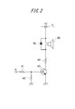
- FIG. 2 shows an example of a circuit diagram showing the buzzer driving unit 40 and the buzzer 60 connected thereto.
- the buzzer drive signal P3 generated by the buzzer drive signal generation unit 20 (see FIG. 1) is input to the terminal A in FIG.
- the buzzer drive signal P3 input from the terminal A is divided by the resistors 41 and 42 and applied to the base of the transistor 43 (switching element).
- the transistor 43 becomes conductive, and a current flows in a direction from the DC power source Vs of the voltage V to the buzzer 60, the resistor 44, and the transistor 43.
- the buzzer 60 sounds with a sound having a frequency corresponding to the audible frequency of the buzzer drive signal P3 applied to the base of the transistor 43.
- the volume of the sound that sounds at this time corresponds to the duty ratio of the buzzer drive signal P3, and the buzzer 60 sounds louder as the duty ratio is larger (the pulse ON time is longer).
- the diode 45 is inserted to absorb the counter electromotive force generated in the buzzer 60.
- the clock signal generation unit 10 generates a reference clock signal Pc having a predetermined frequency.
- the predetermined frequency is a predetermined frequency.
- the generation of the reference clock signal Pc may be performed by software, or may be performed by hardware using an oscillation circuit.
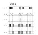
- the non-audible frequency signal generation unit 22 divides the reference clock signal Pc and has a predetermined non-audible frequency (for example, 500 kHz) sufficiently higher than 2 kHz that is the frequency of the sound output from the buzzer 60.
- a non-audible frequency pulse signal P0 is generated (FIG. 3A). This frequency division may be performed by software or may be performed using hardware having a frequency divider function.
- the inaudible frequency pulse signal P0 generated in this way is input to the pulse count unit 24, and is counted until the number of pulses reaches a predetermined value n (126 in this embodiment).
- n a predetermined value
- the count value is returned to 0 and the counting of the number of pulses of the inaudible frequency pulse signal P0 is repeated again.
- the counter signal Ct shown in FIG. 3B is generated.
- the audible frequency signal generator 26 maintains the high level (ON) or the low level (OFF) until the number of pulses constituting the non-audible frequency pulse signal P0 reaches the predetermined value n, When a pulse having a value n is measured, a signal for switching between a high level and a low level is generated. As a result, an audible frequency pulse signal P1 shown in FIG. 3C is generated.
- the signal synthesizer 28 synthesizes the non-audible frequency pulse signal P0 and the audible frequency pulse signal P1 by calculating the logical product of the non-audible frequency pulse signal P0 and the audible frequency pulse signal P1, and then synthesizes the synthesized frequency pulse signal. P2 is generated.
- a non-audible frequency pulse signal is synthesized in a section where the audible frequency pulse signal is at a high level (ON).
- the buzzer drive signal P3 is generated by changing the duty ratio Di of the inaudible frequency pulse signal P0 synthesized in the synthesized frequency pulse signal P2.
- This generation method will be described with reference to FIGS.
- the duty ratio Di is changed in order to prevent abnormal noises generated at the beginning and end of the buzzer as described above.
- the duty ratio Di is changed in order to prevent abnormal noises generated at the beginning and end of the buzzer as described above.
- by changing the duty ratio Di and gradually increasing the voltage applied to the buzzer 60 at the beginning of the buzzer 60 it is possible to prevent a large inrush current from flowing through the buzzer 60 and By gradually lowering the voltage applied to the buzzer 60 at the end of the ringing, large back electromotive force is prevented from being generated in the buzzer 60.
- the synthesized frequency pulse signal P2 includes a section including the inaudible frequency pulse signal P0 and a low level section.
- sections including the non-audible frequency pulse signal P0 are defined as sections R1, R2,..., Ri,..., Rn in order from the left side of FIG.
- the first duty ratio setting unit 30 stores in advance the duty ratios D1, D2,..., Di,..., Dn set for each section R1, R2,. Has been.
- the duty ratio Di corresponding to the section Ri is the first.
- the duty ratio of the section Ri is changed to Di based on the value of the duty ratio Di read out from the 1 duty ratio setting unit 30 and read out.
- the number of pulses constituting the non-audible frequency pulse signal P0 included in the section Ri is included in the section Ri since the frequency of the non-audible frequency pulse signal P0 and the length (time) of the section Ri are known in advance.
- the duty ratio in the section Ri can be changed to a predetermined value by thinning out the number of pulses constituting the non-audible frequency pulse signal P0 according to the set duty ratio.
- the value of the duty ratio Di corresponding to each section Ri stored in advance in the first duty ratio setting unit 30 is read at high speed by the DMA function, and the duty ratio with respect to the composite frequency pulse signal P2 is read.
- the duty ratio is changed by using the value of the duty ratio Di transferred to the memory used for the setting.
- FIG. 4 shows a CR filter, which is a typical low-pass filter, in which a DC power supply 55 having a voltage E is connected to a resistor 50 having a resistance value R and a capacitor 49 having a capacitance C via a switch 52.
- the circuit of FIG. 4 acts as a low-pass filter, when an AC power supply having a certain frequency is connected instead of the DC power supply 55, the frequency f c calculated by (Equation 3) among the frequencies of the AC power supply.
- the above components are cut.
- f c 1 / 2 ⁇ RC (Formula 3)
- the frequency f c is called the cutoff frequency.
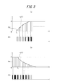
- FIG. 5A is a diagram showing a waveform of the voltage e applied to the buzzer 60 when the buzzer drive signal P3 shown in FIG. 3E is input to the buzzer drive unit 40 of FIG. .
- FIG. 5B is a diagram illustrating a waveform of the voltage e applied to the buzzer 60 when the buzzer drive signal P3 input to the buzzer drive unit 40 is stopped.
- FIGS. 5A and 5B also show the voltage e 0 (t) appearing at both ends of the capacitor 49 in FIG.
- the duty ratio Di of the buzzer drive signal P3 is set to gradually increase as described above, immediately after the time t0 when the buzzer drive signal P3 is input, the duty ratio is increased.
- the amplitude of the voltage e applied to the buzzer 60 is reduced, and as the duty ratio Di is gradually increased, the amplitude of the voltage e applied to the buzzer 60 is increased.
- the duty ratio Di becomes a predetermined constant value, and the amplitude of the voltage e applied to the buzzer 60 becomes a constant magnitude.
- the duty ratio Di of the section Ri is ( by setting according to equation 4), in a pseudo manner, composed of CR filter, be via a low-pass filter having a cut-off frequency f c, produce a state equivalent to the case of inputting the audio frequency pulse signal P1 it can.
- Di (E / gh) * ⁇ 1-exp ( ⁇ 2 ⁇ f c t) ⁇ (Formula 4)
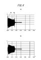
- FIG. 6A shows the voltage e applied to the buzzer 60 when the audible frequency pulse signal P1 having a constant duty ratio is input to the buzzer driving unit 40 without passing through the low-pass filter and the buzzer 60 is blown. It is a waveform showing the amplitude of.
- FIG. 6B shows that the buzzer driving signal P3 set to the predetermined duty ratio Di in the first duty ratio setting unit 30 is input to the buzzer driving unit 40 without passing through the low-pass filter, and the buzzer 60 is blown. It is a waveform showing the amplitude of the voltage e applied to the buzzer 60 when
- spike-like noise N1 is generated at the beginning of the voltage e applied to the buzzer 60, and spike-like noise N2 is further added to the end of the voltage e applied to the buzzer 60. You can see that it has occurred. Then, when the noises N1 and N2 are applied to the buzzer 60, instantaneous noise is generated from the buzzer 60.
- the amplitude of the voltage e applied to the buzzer 60 is such that the rising voltage at the first part and the falling voltage at the last part change slowly, The output waveform when the rectangular wave is passed through the CR filter is reproduced. And the noise N1, N2 which generate
- Step S10 The clock signal generator 10 generates the reference clock signal Pc.
- Step S20 The non-audible frequency signal generator 22 divides the reference clock signal Pc to generate a non-audible frequency pulse signal P0 having a predetermined non-audible frequency.
- Step S30 In the pulse count unit 24, the number of inaudible frequency pulse signals P0 is counted to generate a counter signal Ct.
- Step S40 The audible frequency signal generator 26 generates an audible frequency pulse signal P1 based on the non-audible frequency pulse signal P0 and the counter signal Ct.
- Step S50 In the signal synthesizer 28, a logical product of the non-audible frequency pulse signal P0 and the audible frequency pulse signal P1 is calculated to generate a synthesized frequency pulse signal P2.
- Step S60 In the first duty ratio setting unit 30, the duty ratio of the non-audible frequency pulse signal P0 synthesized in the synthesized frequency pulse signal P2 is changed to a preset Di over the first predetermined period. Further, in the second duty ratio setting unit 32, the signal whose duty ratio is set by the first duty ratio setting unit 30 is changed to a preset Di over the last predetermined period of the signal. Then, the buzzer drive signal P3 is generated.
- Step S70 The buzzer driving signal P3 is input to the buzzer driving unit 40 and the buzzer 60 is sounded.
- the non-audible frequency signal generation unit 22 generates the non-audible frequency pulse signal P0 having a predetermined non-audible frequency, and generates the audible frequency signal.
- the unit 26 generates an audible frequency pulse signal P1 having an audible frequency having a predetermined audible frequency lower than the non-audible frequency from the non-audible frequency pulse signal P0.
- the signal synthesizer 28 synthesizes the inaudible frequency pulse signal P0 and the audible frequency pulse signal P1, and the synthesized frequency pulse signal in which the inaudible frequency pulse signal P0 is synthesized during the ON time of the audible frequency pulse signal P1.
- the first duty ratio setting unit 30 gradually changes the duty ratio Di of the inaudible frequency pulse signal P0 synthesized in the synthesized frequency pulse signal P2 over the first predetermined period of the synthesized frequency pulse signal P2.
- the buzzer driving signal P3 is generated by setting it to be large.
- the buzzer drive unit 40 is applied to the buzzer 60 in order to sound the buzzer 60 with a sound having a volume corresponding to the pitch of the buzzer drive signal P3 and a duty ratio Di of the buzzer drive signal P3.
- the peak value of the voltage e gradually increases with time immediately after the application of the buzzer drive signal P3, whereby the occurrence of an inrush current can be prevented. For this reason, the buzzer 60 can be sounded without mixing noise without inserting a low-pass filter into the buzzer driving unit 40.
- the non-audible frequency signal generation unit 22 generates a non-audible frequency pulse signal P0 having a predetermined non-audible frequency
- the audible frequency signal generation unit 26 is non-audible.
- An audible frequency pulse signal P1 having an audible frequency having a predetermined audible frequency lower than the non-audible frequency is generated from the frequency pulse signal P0.
- the signal synthesizer 28 synthesizes the inaudible frequency pulse signal P0 and the audible frequency pulse signal P1, and the synthesized frequency pulse in which the inaudible frequency pulse signal P0 is synthesized during the ON time of the audible frequency pulse signal P1.
- a signal P2 is generated.
- the first duty ratio setting unit 30 gradually changes the duty ratio Di of the inaudible frequency pulse signal P0 synthesized in the synthesized frequency pulse signal P2 over the last predetermined period of the synthesized frequency pulse signal P2.
- the buzzer driving signal P3 is generated by setting it to be small.
- the buzzer driving unit 40 is applied to the buzzer 60 in order to sound the buzzer 60 with a sound having a sound level corresponding to the frequency of the buzzer driving signal P3 and a volume corresponding to the duty ratio Di of the buzzer driving signal P3.
- the buzzer 60 Since the peak value of the voltage e gradually decreases with time immediately after the end of the buzzer driving signal P3, it is possible to prevent the occurrence of back electromotive force when the buzzer 60, which is an inductive load, is turned off. . For this reason, the buzzer 60 can be sounded without mixing noise without inserting a low-pass filter into the buzzer driving unit 40.
- the duty ratio Di of the inaudible frequency pulse signal P0 synthesized in the synthesized frequency pulse signal P2 is the synthesized frequency pulse signal.
- the duty ratio Di of the inaudible frequency pulse signal P0 synthesized in the synthesized frequency pulse signal P2 is the synthesized frequency pulse signal.
- the buzzer 60 which is an inductive load, is turned off by blowing the buzzer 60 using the buzzer drive signal P3 set to gradually decrease over the last predetermined period of P2. Generation of electric power can be prevented. For this reason, the buzzer 60 can be blown without mixing abnormal noise without passing the buzzer drive signal P3 through the low-pass filter.
- the duty ratio Di of the inaudible frequency pulse signal P0 synthesized in the synthesized frequency pulse signal P2 is set individually for each of the sections R1, R2,..., Ri,.
- This duty ratio is collectively set in the time axis direction with respect to the non-audible frequency pulse signal P0, and the non-audible frequency pulse signal P0 thus set with the duty ratio is synthesized with the audio frequency pulse signal P1.
- the buzzer drive signal P3 may be generated. In this case, it is not necessary to prepare the first duty ratio setting unit 30 and the second duty ratio setting unit 32 individually as shown in FIG. 1, and this duty ratio setting unit is used as one duty ratio setting unit.
- the buzzer 60 is an example of a case where is sounding with 2 kHz, (Equation 4) using a cut-off frequency f c corresponding to the frequency f 0 of the sound you wish to sounding buzzer 60 Since the value can be set, the number of pulses counted by the pulse counting unit 24 is changed according to the frequency f 0 , and the audio frequency signal generating unit 26 generates the audio frequency pulse signal P 1 having the frequency f 0 , inaudible frequency pulse signal P 0 audible frequency pulse signals P1 and combined by the combining unit 28, a duty ratio so as to duty ratio Di setting pattern corresponding to the cut-off frequency f c which is set in accordance with the frequency f 0 By generating the buzzer driving signal P3 in which Di is changed and causing the buzzer 60 to ring by the buzzer driving signal P3 thus generated, the buzzer 60 The frequency f 0, can be sounding without contamination of noise.
- the duty ratio Di of the buzzer drive signal P3 is set in the first duty ratio setting unit 30 and / or the second duty ratio setting unit 32, and thus the duty ratio is set.
- the voltage waveform e generated when the buzzer driving signal P3 with the ratio Di set is input to the buzzer driving unit 40 is the same as the voltage waveform generated when the audio frequency pulse signal P1 is passed through the low-pass filter. Therefore, the same effect as that obtained when the low-pass filter is inserted into the buzzer driving unit 40 can be exhibited. And thereby, the buzzer 60 can be sounded without mixing of an abnormal sound, without inserting a low-pass filter in the buzzer drive part 40.
Landscapes
- Physics & Mathematics (AREA)
- Engineering & Computer Science (AREA)
- Acoustics & Sound (AREA)
- Multimedia (AREA)
- Signal Processing (AREA)
- Amplifiers (AREA)
- Control Of Washing Machine And Dryer (AREA)
- Catching Or Destruction (AREA)
- Telephone Function (AREA)
Abstract
ブザーを、異音の混入なく吹鳴させる。 非可聴周波数信号生成部22が非可聴周波数を有する非可聴周波数パルス信号P0を生成し、可聴周波数信号生成部26が非可聴周波数パルス信号P0から、可聴周波数を有する可聴周波数パルス信号P1を生成して、信号合成部28が、可聴周波数パルス信号P1のON時間の中に非可聴周波数パルス信号P0が合成された合成周波数パルス信号P2を生成し、第1デューティー比設定部30が、合成周波数パルス信号P2の中に合成された非可聴周波数パルス信号P0のデューティー比Diを、合成周波数パルス信号P2の最初の所定の期間に亘って徐々に大きくなるように設定してブザー駆動信号P3を生成し、ブザー駆動部40が、ブザー駆動信号P3の周波数に応じた音の高さとブザー駆動信号P3のデューティー比に応じた音量でブザー60を吹鳴させる。
Description
本出願は、日本国特許出願2012-282746号(2012年12月26日出願)の優先権を主張するものであり、当該出願の開示全体を、ここに参照のために取り込む。
本発明は、ビープ音を出力するブザー出力制御装置及びブザー出力制御方法に関するものである。
自動車などの車両では、予期せぬ様々な事象の発生(例えば、ドアの締め忘れやライトの消し忘れ等)を即時に運転者に伝達して注意を喚起するために、ブザーを吹鳴させることによってビープ音を発生させている。このビープ音は、出力したい音の周波数(例えば2kHz)に対応した周波数を有する矩形波をブザーの駆動回路に入力して、ブザーに与えることによって発生させていた。
このようなブザー駆動回路は、一般的に矩形波を入力する構成になっており、矩形波の入力を行った瞬間にブザーの駆動回路に大きな突入電流が発生して、その突入電流の影響によって、ブザーから出力される音に瞬間的に異音が発生してしまう場合があった。また、矩形波の入力が終了した瞬間には、誘導性負荷であるブザーに発生する逆起電力の影響によって、瞬間的に異音が発生する場合があった。
そこで、ブザーに入力される信号のレベルの急激な変動を緩和して、この異音の発生を防止するために、矩形波の入力段にローパスフィルタ(例えば、抵抗とコンデンサからなるCRフィルタ)を挿入して、このローパスフィルタの作用によって矩形波をなまらせることにより、ブザーに入力される信号のレベルが急激に変動しないようにしている(例えば、特許文献1)。
しかしながら、特許文献1に記載されたブザー駆動回路によると、矩形波の入力段にローパスフィルタ(例えばCRフィルタ)の挿入が必要になるため、ブザー駆動回路を構成する部品点数が増えてしまうという問題があった。
本発明は上記事情に鑑みなされたもので、ブザー駆動回路にローパスフィルタを挿入することなく、ブザーを、異音の混入なく吹鳴させることができるブザー出力制御装置およびブザー出力制御方法を提供することを目的とする。
本発明に係るブザー出力制御装置およびブザー出力制御方法は、ブザー駆動回路にローパスフィルタを用いることなく、ブザーを、異音の混入なく吹鳴させるものである。
すなわち、本発明に係るブザー出力制御装置は、入力されたブザー駆動信号の周波数に応じた音の高さと前記ブザー駆動信号のデューティー比に応じた音量を有する音を出力するブザーと、所定の非可聴周波数を有する非可聴周波数パルス信号を生成する非可聴周波数信号生成部と、前記非可聴周波数よりも低い所定の可聴周波数を有する可聴周波数パルス信号を生成する可聴周波数信号生成部と、前記非可聴周波数パルス信号と前記可聴周波数パルス信号とを合成して、前記可聴周波数パルス信号のON時間の中に、前記非可聴周波数パルス信号が合成された合成周波数パルス信号とする信号合成部と、前記合成周波数パルス信号に合成された非可聴周波数パルス信号のデューティー比が、前記合成周波数パルス信号の最初の所定の期間に亘って徐々に大きくなるように設定されたブザー駆動信号を生成する第1デューティー比設定部と、前記ブザー駆動信号によって前記ブザーを吹鳴させるブザー駆動部と、を有することを特徴とする。
このように構成されたブザー出力制御装置によれば、非可聴周波数信号生成部が所定の非可聴周波数を有する非可聴周波数パルス信号を生成し、可聴周波数信号生成部が非可聴周波数よりも低い所定の可聴周波数を有する可聴周波数パルス信号を生成して、信号合成部が非可聴周波数パルス信号と可聴周波数パルス信号とを合成して、可聴周波数パルス信号のON時間の中に、非可聴周波数パルス信号が合成された合成周波数パルス信号を生成し、第1デューティー比設定部が、合成周波数パルス信号の中に合成された非可聴周波数パルス信号のデューティー比を、合成周波数パルス信号の最初の所定の期間に亘って徐々に大きくなるように設定してブザー駆動信号を生成し、ブザー駆動部が、ブザー駆動信号の周波数に応じた音の高さとブザー駆動信号のデューティー比に応じた音量を有する音でブザーを吹鳴させるため、ブザーに印加される電圧の波高値が、ブザー駆動信号の印加直後に時間とともに徐々に高くなることによって突入電流の発生を防止することができるため、ブザー駆動部にローパスフィルタを挿入することなく、ブザーを異音の混入なしに吹鳴させることができる。
また、本発明に係るブザー出力制御装置は、入力されたブザー駆動信号の周波数に応じた音の高さと前記ブザー駆動信号のデューティー比に応じた音量を有する音を出力するブザーと、所定の非可聴周波数を有する非可聴周波数パルス信号を生成する非可聴周波数信号生成部と、前記非可聴周波数よりも低い所定の可聴周波数を有する可聴周波数パルス信号を生成する可聴周波数信号生成部と、前記非可聴周波数パルス信号と前記可聴周波数パルス信号とを合成して、前記可聴周波数パルス信号のON時間の中に、前記非可聴周波数パルス信号が合成された合成周波数パルス信号とする信号合成部と、前記合成周波数パルス信号に合成された非可聴周波数パルス信号のデューティー比が、前記合成周波数パルス信号の最後の所定の期間に亘って徐々に小さくなるように設定されたブザー駆動信号を生成する第2デューティー比設定部と、前記ブザー駆動信号によって前記ブザーを吹鳴させるブザー駆動部と、を有することを特徴とする。
このように構成されたブザー出力制御装置によれば、非可聴周波数信号生成部が所定の非可聴周波数を有する非可聴周波数パルス信号を生成し、可聴周波数信号生成部が非可聴周波数よりも低い所定の可聴周波数を有する可聴周波数パルス信号を生成して、信号合成部が非可聴周波数パルス信号と可聴周波数パルス信号とを合成して、可聴周波数パルス信号のON時間の中に、非可聴周波数パルス信号が合成された合成周波数パルス信号を生成し、第1デューティー比設定部が、合成周波数パルス信号の中に合成された非可聴周波数パルス信号のデューティー比を、合成周波数パルス信号の最初の所定の期間に亘って徐々に小さくなるように設定してブザー駆動信号を生成し、ブザー駆動部が、ブザー駆動信号の周波数に応じた音の高さとブザー駆動信号のデューティー比に応じた音量を有する音でブザーを吹鳴させるため、ブザーに印加される電圧の波高値が、ブザー駆動信号の終了直後に時間とともに徐々に低くなることによって誘導性負荷であるブザーがOFFになったときの逆起電力の発生を防止することができるため、ブザー駆動部にローパスフィルタを挿入することなく、ブザーを異音の混入なしに吹鳴させることができる。
また、本発明に係るブザー出力制御方法は、所定の非可聴周波数を有する非可聴周波数パルス信号を生成して、前記非可聴周波数よりも低い所定の可聴周波数を有する可聴周波数パルス信号を生成して、前記可聴周波数パルス信号のON時間の中に前記非可聴周波数パルス信号を合成して合成周波数パルス信号を生成して、前記合成周波数パルス信号の中に合成された非可聴周波数パルス信号のデューティー比が、前記合成周波数パルス信号の最初の所定の期間に亘って徐々に大きくなるように設定されたブザー駆動信号を生成して、こうして生成されたブザー駆動信号によって、前記ブザー駆動信号の周波数に応じた音の高さと前記ブザー駆動信号のデューティー比に応じた音量を有する音でブザーを吹鳴させることを特徴とする。
このように構成されたブザー出力制御方法によれば、合成周波数パルス信号の中に合成された非可聴周波数パルス信号のデューティー比が、合成周波数パルス信号の最初の所定の期間に亘って徐々に大きくなるように設定されたブザー駆動信号を用いてブザーを吹鳴させることにより、突入電流の発生を防止することができるため、ブザー駆動信号をローパスフィルタに通すことなしに、異音の混入なくブザーを吹鳴させることができる。
また、本発明に係るブザー出力制御方法は、所定の非可聴周波数を有する非可聴周波数パルス信号を生成して、前記非可聴周波数よりも低い所定の可聴周波数を有する可聴周波数パルス信号を生成して、前記可聴周波数パルス信号のON時間の中に前記非可聴周波数パルス信号を合成して合成周波数パルス信号を生成して、前記合成周波数パルス信号の中に合成された非可聴周波数パルス信号のデューティー比が、前記合成周波数パルス信号の最後の所定の期間に亘って徐々に小さくなるように設定されたブザー駆動信号を生成して、こうして生成されたブザー駆動信号によって、前記ブザー駆動信号の周波数に応じた音の高さと前記ブザー駆動信号のデューティー比に応じた音量を有する音でブザーを吹鳴させることを特徴とする。
このように構成されたブザー出力制御方法によれば、合成周波数パルス信号の中に合成された非可聴周波数パルス信号のデューティー比が、合成周波数パルス信号の最後の所定の期間に亘って徐々に小さくなるように設定されたブザー駆動信号を用いてブザーを吹鳴させることにより、誘導性負荷であるブザーがOFFになったときの逆起電力の発生を防止することができるため、ブザー駆動信号をローパスフィルタに通すことなしに、異音の混入なくブザーを吹鳴させることができる。
本発明に係るブザー出力制御装置およびブザー出力制御方法によれば、ブザー駆動回路にCRフィルタを用いることなく、ブザーを、その鳴り初めや鳴り終わりに異音を生じることなく吹鳴させることができるという効果が得られる。
以下、本発明に係るブザー出力制御装置およびブザー出力制御方法の実施例について、図面を参照して説明する。
[実施例1の構成の説明]
以下、本発明の第1の実施例について説明する。本発明を適用したブザー出力制御装置100は、図1に示すように、図示しない車両に備えられて、車両のドアの締め忘れやライトの消し忘れ等を報知するブザー60と、ブザー60を吹鳴させる信号であるブザー駆動信号P3の元になる、所定の周波数のパルス信号である基準クロック信号Pcを発生するクロック信号生成部10と、基準クロック信号Pcに基づいてブザー駆動信号P3を生成するブザー駆動信号生成部20と、ブザー駆動信号生成部20で生成されたブザー駆動信号P3をブザー60に印加して、ブザー60を吹鳴させるブザー駆動部40とから構成されている。
以下、本発明の第1の実施例について説明する。本発明を適用したブザー出力制御装置100は、図1に示すように、図示しない車両に備えられて、車両のドアの締め忘れやライトの消し忘れ等を報知するブザー60と、ブザー60を吹鳴させる信号であるブザー駆動信号P3の元になる、所定の周波数のパルス信号である基準クロック信号Pcを発生するクロック信号生成部10と、基準クロック信号Pcに基づいてブザー駆動信号P3を生成するブザー駆動信号生成部20と、ブザー駆動信号生成部20で生成されたブザー駆動信号P3をブザー60に印加して、ブザー60を吹鳴させるブザー駆動部40とから構成されている。
ブザー60は、例えば圧電ブザーによって構成されている。圧電ブザーは、圧電素子と金属板が貼り合わされた構造を有しており、圧電素子に外部から電圧を引加することによって、圧電素子が伸縮変形を起こし、この伸縮変形が金属板に伝わって金属板が撓んで音を発生する。
ブザー駆動信号生成部20は、さらに、基準クロック信号Pcを分周して所定の非可聴周波数を有する非可聴周波数パルス信号P0とする非可聴周波数信号生成部22と、非可聴周波数信号生成部22で生成された非可聴周波数パルス信号P0のパルス数をカウントするパルスカウント部24と、パルスカウント部24でカウントされた非可聴周波数パルス信号P0のパルス数に基づいて、前記非可聴周波数よりも低い所定の可聴周波数を有する可聴周波数パルス信号P1を生成する可聴周波数信号生成部26と、可聴周波数パルス信号P1と非可聴周波数パルス信号P0を合成して、可聴周波数パルス信号P1がONである区間に非可聴周波数パルス信号P0が合成された合成周波数パルス信号P2を生成する信号合成部28と、合成周波数パルス信号P2の中に合成された非可聴周波数パルス信号P0の最初の所定期間のデューティー比を所定の値に設定してブザー駆動信号P3を生成する第1デューティー比設定部30と、合成周波数パルス信号P2の非可聴周波数パルス信号の最後の所定期間のデューティー比を所定の値に設定してブザー駆動信号P3を生成する第2デューティー比設定部32と、から構成されている。
次に、図2を参照して、ブザー駆動部40の構成について説明する。
図2は、ブザー駆動部40と、そこに接続されたブザー60を示す回路図の一例を示すものである。ブザー駆動信号生成部20(図1参照)で生成されたブザー駆動信号P3は、図2の端子Aに入力される。
端子Aから入力されたブザー駆動信号P3は、抵抗41,42で分圧されてトランジスタ43(スイッチング素子)のベースに印加される。これによって、トランジスタ43が導通状態となり、電圧Vの直流電源Vsから、ブザー60,抵抗44,トランジスタ43に至る方向に電流が流れる。そして、このとき、トランジスタ43のベースに印加されたブザー駆動信号P3の可聴周波数に応じた周波数の音でブザー60が吹鳴する。そして、このときに吹鳴する音の大きさは、ブザー駆動信号P3のデューティー比に対応し、デューティー比が大きいほど(パルスのON時間が長いほど)ブザー60は大きい音で吹鳴する。なお、ダイオード45は、ブザー60に発生する逆起電力を吸収するために挿入されたものである。
[合成周波数パルス信号P2の生成方法の説明]
ここで、ブザー60から2kHzの周波数のビープ音を発生させる場合を例にあげて、ブザー駆動信号P3の生成方法について、図1,図3を用いて説明する。
ここで、ブザー60から2kHzの周波数のビープ音を発生させる場合を例にあげて、ブザー駆動信号P3の生成方法について、図1,図3を用いて説明する。
まず、クロック信号生成部10において、所定の周波数を有する基準クロック信号Pcを発生する。所定周波数は予め決められた周波数である。基準クロック信号Pcの生成はソフトウェアで行ってもよいし、発振回路を用いたハードウェアで行ってもよい。
次に、非可聴周波数信号生成部22において、基準クロック信号Pcを分周して、ブザー60から出力させる音の周波数である2kHzよりも十分に高い、所定の非可聴周波数(例えば500kHz)を有する非可聴周波数パルス信号P0を生成する(図3(a))。この分周はソフトウェアで行ってもよいし、分周器の機能を有するハードウェアを用いて行ってもよい。
こうして生成された非可聴周波数パルス信号P0はパルスカウント部24に入力されて、パルスカウント部24において、パルス数が所定の値n(本実施例の場合126個)になるまでの間、カウントされる。そして、パルス数が所定の値nになったら、カウント値を0に戻して、再び非可聴周波数パルス信号P0のパルス数のカウントを繰り返す。このようにして、図3(b)に示すカウンタ信号Ctが生成される。
そして、可聴周波数信号生成部26において、非可聴周波数パルス信号P0を構成するパルス数が所定の値nになるまでの間はハイレベル(ON)、またはローレベル(OFF)を維持して、所定の値nのパルスが計測されたら、ハイレベルとローレベルが切り替わる信号を生成する。これによって、図3(c)に示す可聴周波数パルス信号P1が生成される。
次に、信号合成部28において、非可聴周波数パルス信号P0と可聴周波数パルス信号P1の論理積を計算することによって、非可聴周波数パルス信号P0と可聴周波数パルス信号P1を合成し、合成周波数パルス信号P2を生成する。こうして合成された合成周波数パルス信号P2の中には、図3(d)に示すように、可聴周波数パルス信号がハイレベル(ON)の区間に、非可聴周波数パルス信号が合成される。
[ブザー駆動信号P3の生成方法の説明]
次に、合成周波数パルス信号P2の中に合成された非可聴周波数パルス信号P0のデューティー比Diを変更して、ブザー駆動信号P3を生成する。この生成方法について、図1,図3を用いて説明する。なお、デューティー比Diを変更するのは、前述したように、ブザーの鳴り始めと鳴り終わりに発生する異音を防止するためである。そして、デューティー比Diを変更して、ブザー60の鳴り始めにはブザー60に引加される電圧を徐々に高くすることによって、ブザー60に大きな突入電流が流れることを防止するとともに、ブザー60の鳴り終わりにはブザー60に印加される電圧を徐々に低くすることによって、ブザー60に大きな逆起電力が発生することを防止する。
次に、合成周波数パルス信号P2の中に合成された非可聴周波数パルス信号P0のデューティー比Diを変更して、ブザー駆動信号P3を生成する。この生成方法について、図1,図3を用いて説明する。なお、デューティー比Diを変更するのは、前述したように、ブザーの鳴り始めと鳴り終わりに発生する異音を防止するためである。そして、デューティー比Diを変更して、ブザー60の鳴り始めにはブザー60に引加される電圧を徐々に高くすることによって、ブザー60に大きな突入電流が流れることを防止するとともに、ブザー60の鳴り終わりにはブザー60に印加される電圧を徐々に低くすることによって、ブザー60に大きな逆起電力が発生することを防止する。
ここで、ブザー60に入力するブザー駆動信号P3のデューティー比Diを小さくすると(パルスのON時間を短くすると)、ブザー60に加えられる電力が小さくなるため、ブザー60に印加される電圧が低くなることによって、ブザー60から出力される音量も小さくなる。逆に、ブザー60に入力するブザー駆動信号P3のデューティー比Diを大きくすると(パルスのON時間を長くすると)、ブザー60に加えられる電力が大きくなるため、ブザー60に印加される電圧が高くなることによって、ブザー60から出力される音量が大きくなる。
次に、このデューティー比Diの変更方法について説明する。合成周波数パルス信号P2は、非可聴周波数パルス信号P0を含む区間と、ローレベルの区間とからなる。ここで、非可聴周波数パルス信号P0を含む区間を、図3(d)の左側から順に、区間R1,R2,…,Ri,…,Rnとする。
第1デューティー比設定部30には、合成周波数パルス信号P2の各区間R1,R2…,Ri,…,Rnに対して設定するデューティー比D1,D2,…,Di,…,Dnが、予め記憶されている。
そして、第1デューティー比設定部30に入力された合成周波数パルス信号P2の各区間R1,R2,…,Ri,…,Rnが検出されるたびに、その区間Riに対応するデューティー比Diが第1デューティー比設定部30から読み出されて、読み出されたデューティー比Diの値に基づいて、区間Riのデューティー比がDiに変更される。
このとき、区間Riに含まれている非可聴周波数パルス信号P0を構成するパルス数は、非可聴周波数パルス信号P0の周波数と、区間Riの長さ(時間)が予めわかるため、区間Riに含まれる非可聴周波数パルス信号P0を構成するパルス数を、設定するデューティー比に応じて間引くことにより、区間Riにおけるデューティー比を所定の値に変更することができる。
なお、非可聴周波数パルス信号P0の周波数は高いため、第1デューティー比設定部30に記憶されたデューティー比Diの読み出しと合成周波数パルス信号P2のデューティー比の変更は高速で行う必要がある。そのため、この読み出しと変更は、例えば、メモリに記憶した情報をCPUから読み出すのではなく、メモリ間で直接情報をやり取りすることができる機能、所謂DMA(Direct Memory Access)機能を利用することによって、高速に実行することができる。
すなわち、予め第1デューティー比設定部30に記憶しておいた、各区間Riに対応するデューティー比Diの値が、DMA機能によって高速に読み出されて、合成周波数パルス信号P2に対してデューティー比の設定を行う際に使用するメモリに転送されて、こうして転送されたデューティー比Diの値を用いてデューティー比の変更が行われる。
[ブザー駆動信号P3のデューティー比の設定方法の説明]
次に、デューティー比D1,D2,…,Di,…,Dnの具体的な設定方法について説明する。前述したように、デューティー比Diを小さくすると、ブザー60から出力される音量が小さくなり、逆にデューティー比Diを大きくすると、ブザー60から出力される音量が大きくなる。そして、音量の大きくなる程度と小さくなる程度は、従来、ブザー駆動部に挿入していたローパスフィルタの周波数応答の程度を表わす時定数τと等しくなるように設定するのが望ましい。
次に、デューティー比D1,D2,…,Di,…,Dnの具体的な設定方法について説明する。前述したように、デューティー比Diを小さくすると、ブザー60から出力される音量が小さくなり、逆にデューティー比Diを大きくすると、ブザー60から出力される音量が大きくなる。そして、音量の大きくなる程度と小さくなる程度は、従来、ブザー駆動部に挿入していたローパスフィルタの周波数応答の程度を表わす時定数τと等しくなるように設定するのが望ましい。
図4は、電圧Eの直流電源55が、スイッチ52を介して、抵抗値Rを有する抵抗50と、容量Cを有するコンデンサ49と接続された、代表的なローパスフィルタであるCRフィルタを示す。
図4において、スイッチ52を閉じたときに、コンデンサ49の両端に発生する電圧は、時刻をtとして、e0(t)で表わされるものとする。このとき、電圧e0(t)は(式1)で表わされる。
e0(t)=E*{1-exp(-t/RC)} (式1)
e0(t)=E*{1-exp(-t/RC)} (式1)
すなわち、コンデンサ49の両端に発生する電圧e0(t)は、スイッチ52の投入後に、時定数τ=RCによって定まる時間に応じた速度で徐々に増加する。
一方、図4において、一度閉じたスイッチ52を開いたときに、コンデンサ49の両端に発生する電圧e0(t)は、時刻をtとして、(式2)で表わされる。
e0(t)=E*exp(-t/RC) (式2)
e0(t)=E*exp(-t/RC) (式2)
すなわち、コンデンサ49の両端に発生する電圧e0(t)は、スイッチ52の開放後に、時定数τ=RCによって定まる時間に応じた速度で徐々に減少する。
そして、このようにして生成した、コンデンサ49の両端に発生する電圧e0(t)をブザー60に印加してブザー60を吹鳴させることにより、急激な電圧の変化が緩和されるため、前述した突入電流による異音の発生を防止することができる。
なお、図4の回路はローパスフィルタとして作用するため、直流電源55の代わりに、ある周波数の交流電源を接続したときには、その交流電源の周波数のうち、(式3)で算出される周波数fc以上の成分がカットされる。
fc=1/2πRC (式3)
ここで、周波数fcはカットオフ周波数と呼ばれる。
fc=1/2πRC (式3)
ここで、周波数fcはカットオフ周波数と呼ばれる。
すなわち、ブザーで吹鳴させたい音である可聴周波数パルス信号P1の周波数をf0としたとき、この周波数f0の音を減衰させないために、周波数fcは周波数f0に対して十分高い周波数になるように、抵抗50の抵抗値Rとコンデンサ49の容量Cを選択する必要がある。
図5(a)は、図3(e)に示したブザー駆動信号P3を、図1のブザー駆動部40に入力したときに、ブザー60に印加される電圧eの波形を示した図である。また、図5(b)は、ブザー駆動部40に入力していたブザー駆動信号P3を停止したときに、ブザー60に印加される電圧eの波形を示した図である。
そして、図5(a),(b)には、それぞれ、図4のコンデンサ49の両端に表れる電圧e0(t)を合わせて図示している。
図5(a)に示すように、ブザー駆動信号P3のデューティー比Diを、前述したように徐々に大きくなるように設定することによって、ブザー駆動信号P3を入力した時刻t0の直後は、デューティー比Diが小さいブザー駆動信号P3が入力されることによって、ブザー60に印加される電圧eの振幅は小さくなり、徐々にデューティー比Diが大きくなるにつれて、ブザー60に印加される電圧eの振幅が大きくなり、所定の時間が経つと、デューティー比Diは所定の一定値になるため、ブザー60に印加される電圧eの振幅は一定の大きさとなる。
また、図5(b)に示すように、ブザー駆動信号P3のデューティー比Diを、前述したように徐々に小さくなるように設定することによって、ブザー駆動信号P3の入力を停止する時刻t1の直前には、デューティー比Diが一定の大きい値を有する波形が入力されることによってブザー60に印加される電圧eの振幅は一定の大きさとなっており、時刻t1においてブザー駆動信号P3の入力を停止した後は、デューティー比Diが徐々に小さくなるにつれて、ブザー60に印加される電圧eの振幅が小さくなり、所定の時間が経つと、デューティー比Diが0になって、ブザー60に印加される電圧eの振幅も0になる。
そして、ブザー駆動信号P3のデューティー比Diを適切に設定することによって、このブザー60に印加される電圧eの振幅が、前述したコンデンサ49の両端に表れる電圧e0(t)と同様の時間変化をするように設定することができる。
すなわち、ブザー駆動信号P3のある区間Riのデューティー比をDiとし、ブザー駆動部40が備えるスイッチング素子のゲインをg、ブザー駆動信号P3のパルス電圧をhとすると、区間Riのデューティー比Diを(式4)に従って設定することにより、擬似的に、CRフィルタで構成された、カットオフ周波数fcを有するローパスフィルタを介して、可聴周波数パルス信号P1を入力した場合と等価な状態を作り出すことができる。
Di=(E/gh)*{1-exp(-2πfct)} (式4)
Di=(E/gh)*{1-exp(-2πfct)} (式4)
[本発明の効果の説明]
次に、本発明の効果について、図6を用いて説明する。図6(a)は、デューティー比が一定の可聴周波数パルス信号P1を、ローパスフィルタを介さずにブザー駆動部40に入力してブザー60を吹鳴させたときに、ブザー60に印加される電圧eの振幅を表わす波形である。
次に、本発明の効果について、図6を用いて説明する。図6(a)は、デューティー比が一定の可聴周波数パルス信号P1を、ローパスフィルタを介さずにブザー駆動部40に入力してブザー60を吹鳴させたときに、ブザー60に印加される電圧eの振幅を表わす波形である。
そして、図6(b)は、第1デューティー比設定部30において所定のデューティー比Diに設定されたブザー駆動信号P3を、ローパスフィルタを介さずにブザー駆動部40に入力してブザー60を吹鳴させたときに、ブザー60に印加される電圧eの振幅を表わす波形である。
図6(a)では、ブザー60に印加される電圧eの最初に、スパイク状のノイズN1が発生しており、さらに、ブザー60に印加される電圧eの最後に、スパイク状のノイズN2が発生していることがわかる。そして、このノイズN1,N2がブザー60に印加されることによって、ブザー60からは瞬間的な異音が発生する。
一方、図6(b)では、ブザー60に印加される電圧eの振幅は、その最初の部分の立ち上がり電圧と、最後の部分の立下り電圧が、それぞれ緩やかに変化しており、これは、矩形波をCRフィルタに通したときの出力波形を再現している。そして、図6(a)で発生していたノイズN1,N2の混入もなく、ブザー60を、異音の混入なく吹鳴させることができる。
[実施例1の作用説明]
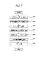
次に、実施例1においてブザー60を吹鳴させる手順について、図7のフローチャートを用いて説明する。
次に、実施例1においてブザー60を吹鳴させる手順について、図7のフローチャートを用いて説明する。
(ステップS10) クロック信号生成部10において基準クロック信号Pcを生成する。
(ステップS20) 非可聴周波数信号生成部22において、基準クロック信号Pcを分周して、所定の非可聴周波数を有する非可聴周波数パルス信号P0を生成する。
(ステップS30) パルスカウント部24において、非可聴周波数パルス信号P0の数がカウントされて、カウンタ信号Ctを生成する。
(ステップS40) 可聴周波数信号生成部26において、非可聴周波数パルス信号P0とカウンタ信号Ctに基づいて可聴周波数パルス信号P1を生成する。
(ステップS50) 信号合成部28において、非可聴周波数パルス信号P0と可聴周波数パルス信号P1の論理積を演算して、合成周波数パルス信号P2を生成する。
(ステップS60) 第1デューティー比設定部30において、合成周波数パルス信号P2の中に合成された非可聴周波数パルス信号P0のデューティー比を、その最初の所定の期間にわたって、予め設定されたDiに変更して、さらに、第2デューティー比設定部32において、第1デューティー比設定部30でデューティー比が設定された信号に対して、その信号の最後の所定の期間にわたって、予め設定されたDiに変更して、ブザー駆動信号P3を生成する。
(ステップS70) ブザー駆動信号P3をブザー駆動部40に入力して、ブザー60を吹鳴させる。
以上、説明したように、実施例1に係るブザー出力制御装置100によれば、非可聴周波数信号生成部22が所定の非可聴周波数を有する非可聴周波数パルス信号P0を生成し、可聴周波数信号生成部26が非可聴周波数パルス信号P0から、非可聴周波数よりも低い所定の可聴周波数を有する可聴周波数を有する可聴周波数パルス信号P1を生成する。そして信号合成部28が非可聴周波数パルス信号P0と可聴周波数パルス信号P1とを合成して、可聴周波数パルス信号P1のON時間の中に、非可聴周波数パルス信号P0が合成された合成周波数パルス信号P2を生成する。そして、第1デューティー比設定部30が、合成周波数パルス信号P2の中に合成された非可聴周波数パルス信号P0のデューティー比Diを、合成周波数パルス信号P2の最初の所定の期間に亘って徐々に大きくなるように設定してブザー駆動信号P3を生成する。ここでブザー駆動部40が、ブザー駆動信号P3の周波数に応じた音の高さとブザー駆動信号P3のデューティー比Diに応じた音量を有する音でブザー60を吹鳴させるため、ブザー60に印加される電圧eの波高値が、ブザー駆動信号P3の印加直後に時間とともに徐々に高くなることによって突入電流の発生を防止することができる。そのため、ブザー駆動部40にローパスフィルタを挿入することなく、ブザー60を異音の混入なしに吹鳴させることができる。
また、実施例1に係るブザー出力制御装置100によれば、非可聴周波数信号生成部22が所定の非可聴周波数を有する非可聴周波数パルス信号P0を生成し、可聴周波数信号生成部26が非可聴周波数パルス信号P0から、非可聴周波数よりも低い所定の可聴周波数を有する可聴周波数を有する可聴周波数パルス信号P1を生成する。そして、信号合成部28が非可聴周波数パルス信号P0と可聴周波数パルス信号P1とを合成して、可聴周波数パルス信号P1のON時間の中に、非可聴周波数パルス信号P0が合成された合成周波数パルス信号P2を生成する。そして、第1デューティー比設定部30が、合成周波数パルス信号P2の中に合成された非可聴周波数パルス信号P0のデューティー比Diを、合成周波数パルス信号P2の最後の所定の期間に亘って徐々に小さくなるように設定してブザー駆動信号P3を生成する。ここで、ブザー駆動部40が、ブザー駆動信号P3の周波数に応じた音の高さとブザー駆動信号P3のデューティー比Diに応じた音量を有する音でブザー60を吹鳴させるため、ブザー60に印加される電圧eの波高値が、ブザー駆動信号P3の終了直後に時間とともに徐々に低くなることによって、誘導性負荷であるブザー60がOFFになったときの逆起電力の発生を防止することができる。そのため、ブザー駆動部40にローパスフィルタを挿入することなく、ブザー60を異音の混入なしに吹鳴させることができる。
また、実施例1に係るブザー出力制御装置100を用いたブザー出力制御方法によれば、合成周波数パルス信号P2の中に合成された非可聴周波数パルス信号P0のデューティー比Diが、合成周波数パルス信号P2の最初の所定の期間に亘って徐々に大きくなるように設定されたブザー駆動信号P3を用いてブザー60を吹鳴させることにより、突入電流の発生を防止することができる。そのため、ブザー駆動信号P3をローパスフィルタに通すことなしに、異音の混入なくブザー60を吹鳴させることができる。
また、実施例1に係るブザー出力制御装置100を用いたブザー出力制御方法によれば、合成周波数パルス信号P2の中に合成された非可聴周波数パルス信号P0のデューティー比Diが、合成周波数パルス信号P2の最後の所定の期間に亘って徐々に小さくなるように設定されたブザー駆動信号P3を用いてブザー60を吹鳴させることにより、誘導性負荷であるブザー60がOFFになったときの逆起電力の発生を防止することができる。そのため、ブザー駆動信号P3をローパスフィルタに通すことなしに、異音の混入なくブザー60を吹鳴させることができる。
なお、本実施例では、合成周波数パルス信号P2の中に合成された非可聴周波数パルス信号P0のデューティー比Diを、区間R1,R2,…,Ri,…,Rn毎に個別に設定したが、このデューティー比は、非可聴周波数パルス信号P0に対して、時間軸方向に亘って一括して設定し、こうしてデューティー比が設定された非可聴周波数パルス信号P0を可聴周波数パルス信号P1と合成して、ブザー駆動信号P3を生成するようにしてもよい。この場合は、図1のように第1デューティー比設定部30と第2デューティー比設定部32をそれぞれ個別に用意する必要はなく、1つのデューティー比設定部として、このデューティー比設定部を、非可聴周波数信号生成部22と信号合成部28の間に設置する構成とすればよい。すなわち、同じブザー駆動信号P3の波形が得られるのであれば、信号処理の手順は、図1に示したブザー駆動信号生成部20の内部構成に限定されるものではない。
なお、本実施例では、合成周波数パルス信号P2の中に合成された非可聴周波数パルス信号P0のデューティー比Diを、区間R1,R2,…,Ri,…,Rn毎に個別に設定したが、このデューティー比は、非可聴周波数パルス信号P0に対して、時間軸方向に亘って一括して設定し、こうしてデューティー比が設定された非可聴周波数パルス信号P0を可聴周波数パルス信号P1と合成して、ブザー駆動信号P3を生成するようにしてもよい。この場合は、図1のように第1デューティー比設定部30と第2デューティー比設定部32をそれぞれ個別に用意する必要はなく、1つのデューティー比設定部として、このデューティー比設定部を、非可聴周波数信号生成部22と信号合成部28の間に設置する構成とすればよい。すなわち、同じブザー駆動信号P3の波形が得られるのであれば、信号処理の手順は、図1に示したブザー駆動信号生成部20の内部構成に限定されるものではない。
また、本実施例は、ブザー60を2kHzで吹鳴させた場合の例であるが、(式4)を用いて、ブザー60で吹鳴させたい音の周波数f0に応じたカットオフ周波数fcの値を設定することができるため、周波数f0に応じてパルスカウント部24でカウントするパルス数を変更して、可聴周波数信号生成部26で周波数f0の可聴周波数パルス信号P1を生成し、信号合成部28で非可聴周波数パルス信号P0と可聴周波数パルス信号P1を合成して、周波数f0に応じて設定したカットオフ周波数fcに応じたデューティー比Diの設定パターンになるようにデューティー比Diが変更されたブザー駆動信号P3を生成して、こうして生成したブザー駆動信号P3によってブザー60を吹鳴させることにより、ブザー60を、任意の周波数f0で、異音の混入なく吹鳴させることができる。
また、このように構成されたブザー出力制御方法によれば、ブザー駆動信号P3のデューティー比Diが、第1デューティー比設定部30および/または第2デューティー比設定部32において設定されて、こうしてデューティー比Diが設定されたブザー駆動信号P3をブザー駆動部40に入力したときに発生する電圧波形eを、可聴周波数パルス信号P1をローパスフィルタに通したときに生成される電圧波形と同じ波形になるように設定することができるため、ブザー駆動部40にローパスフィルタを挿入したのと同様の効果を発揮させることができる。そして、これによって、ブザー駆動部40にローパスフィルタを挿入することなく、ブザー60を、異音の混入なく吹鳴させることができる。
以上、この発明の実施例を図面により詳述してきたが、実施例はこの発明の例示にしか過ぎないものであるため、この発明は実施例の構成にのみ限定されるものではなく、この発明の要旨を逸脱しない範囲の設計の変更等があってもこの発明に含まれることは勿論である。
10 クロック信号生成部
20 ブザー駆動信号生成部
22 非可聴周波数信号生成部
24 パルスカウント部
26 可聴周波数信号生成部
28 信号合成部
30 第1デューティー比設定部
32 第2デューティー比設定部
40 ブザー駆動部
60 ブザー
100 ブザー出力制御装置
20 ブザー駆動信号生成部
22 非可聴周波数信号生成部
24 パルスカウント部
26 可聴周波数信号生成部
28 信号合成部
30 第1デューティー比設定部
32 第2デューティー比設定部
40 ブザー駆動部
60 ブザー
100 ブザー出力制御装置
Claims (4)
- 入力されたブザー駆動信号の周波数に応じた音の高さと前記ブザー駆動信号のデューティー比に応じた音量を有する音を出力するブザーと、
所定の非可聴周波数を有する非可聴周波数パルス信号を生成する非可聴周波数信号生成部と、
前記非可聴周波数よりも低い所定の可聴周波数を有する可聴周波数パルス信号を生成する可聴周波数信号生成部と、
前記非可聴周波数パルス信号と前記可聴周波数パルス信号とを合成して、前記可聴周波数パルス信号のON時間の中に、前記非可聴周波数パルス信号が合成された合成周波数パルス信号とする信号合成部と、
前記合成周波数パルス信号に合成された非可聴周波数パルス信号のデューティー比が、前記合成周波数パルス信号の最初の所定の期間に亘って徐々に大きくなるように設定されたブザー駆動信号を生成する第1デューティー比設定部と、
前記ブザー駆動信号によって前記ブザーを吹鳴させるブザー駆動部と、を有することを特徴とするブザー出力制御装置。 - 入力されたブザー駆動信号の周波数に応じた音の高さと前記ブザー駆動信号のデューティー比に応じた音量を有する音を出力するブザーと、
所定の非可聴周波数を有する非可聴周波数パルス信号を生成する非可聴周波数信号生成部と、
前記非可聴周波数よりも低い所定の可聴周波数を有する可聴周波数パルス信号を生成する可聴周波数信号生成部と、
前記非可聴周波数パルス信号と前記可聴周波数パルス信号とを合成して、前記可聴周波数パルス信号のON時間の中に、前記非可聴周波数パルス信号が合成された合成周波数パルス信号とする信号合成部と、
前記合成周波数パルス信号に合成された非可聴周波数パルス信号のデューティー比が、前記合成周波数パルス信号の最後の所定の期間に亘って徐々に小さくなるように設定されたブザー駆動信号を生成する第2デューティー比設定部と、
前記ブザー駆動信号によって前記ブザーを吹鳴させるブザー駆動部と、を有することを特徴とするブザー出力制御装置。 - 所定の非可聴周波数を有する非可聴周波数パルス信号を生成して、
前記非可聴周波数よりも低い所定の可聴周波数を有する可聴周波数パルス信号を生成して、
前記可聴周波数パルス信号のON時間の中に前記非可聴周波数パルス信号を合成して合成周波数パルス信号を生成して、
前記合成周波数パルス信号の中に合成された非可聴周波数パルス信号のデューティー比が、前記合成周波数パルス信号の最初の所定の期間に亘って徐々に大きくなるように設定されたブザー駆動信号を生成して、
こうして生成されたブザー駆動信号によって、前記ブザー駆動信号の周波数に応じた音の高さと前記ブザー駆動信号のデューティー比に応じた音量を有する音でブザーを吹鳴させることを特徴とするブザー出力制御方法。 - 所定の非可聴周波数を有する非可聴周波数パルス信号を生成して、
前記非可聴周波数よりも低い所定の可聴周波数を有する可聴周波数パルス信号を生成して、
前記可聴周波数パルス信号のON時間の中に前記非可聴周波数パルス信号を合成して合成周波数パルス信号を生成して、
前記合成周波数パルス信号の中に合成された非可聴周波数パルス信号のデューティー比が、前記合成周波数パルス信号の最後の所定の期間に亘って徐々に小さくなるように設定されたブザー駆動信号を生成して、
こうして生成されたブザー駆動信号によって、前記ブザー駆動信号の周波数に応じた音の高さと前記ブザー駆動信号のデューティー比に応じた音量を有する音でブザーを吹鳴させることを特徴とするブザー出力制御方法。
Priority Applications (2)
| Application Number | Priority Date | Filing Date | Title |
|---|---|---|---|
| CN201380066701.9A CN104870255B (zh) | 2012-12-26 | 2013-09-17 | 蜂鸣器输出控制装置以及蜂鸣器输出控制方法 |
| US14/647,256 US9583089B2 (en) | 2012-12-26 | 2013-09-17 | Buzzer output control device and buzzer output control method |
Applications Claiming Priority (2)
| Application Number | Priority Date | Filing Date | Title |
|---|---|---|---|
| JP2012282746A JP5974369B2 (ja) | 2012-12-26 | 2012-12-26 | ブザー出力制御装置およびブザー出力制御方法 |
| JP2012-282746 | 2012-12-26 |
Publications (1)
| Publication Number | Publication Date |
|---|---|
| WO2014103104A1 true WO2014103104A1 (ja) | 2014-07-03 |
Family
ID=51020247
Family Applications (1)
| Application Number | Title | Priority Date | Filing Date |
|---|---|---|---|
| PCT/JP2013/005483 Ceased WO2014103104A1 (ja) | 2012-12-26 | 2013-09-17 | ブザー出力制御装置およびブザー出力制御方法 |
Country Status (4)
| Country | Link |
|---|---|
| US (1) | US9583089B2 (ja) |
| JP (1) | JP5974369B2 (ja) |
| CN (1) | CN104870255B (ja) |
| WO (1) | WO2014103104A1 (ja) |
Cited By (2)
| Publication number | Priority date | Publication date | Assignee | Title |
|---|---|---|---|---|
| CN105279916A (zh) * | 2015-11-17 | 2016-01-27 | 来安县信隆机械科技有限公司 | 一种报警控制电路及报警器 |
| CN114360481A (zh) * | 2021-11-26 | 2022-04-15 | 惠州华阳通用智慧车载系统开发有限公司 | 一种蜂鸣器的去噪驱动方法 |
Families Citing this family (8)
| Publication number | Priority date | Publication date | Assignee | Title |
|---|---|---|---|---|
| JP5974369B2 (ja) * | 2012-12-26 | 2016-08-23 | カルソニックカンセイ株式会社 | ブザー出力制御装置およびブザー出力制御方法 |
| CN105513584B (zh) * | 2015-12-30 | 2023-05-05 | 苏州蓝博控制技术有限公司 | 蜂鸣输出方法及装置 |
| CN105719633B (zh) * | 2016-03-22 | 2019-10-11 | 奇瑞汽车股份有限公司 | 报警声音产生方法和装置 |
| CN108780636A (zh) * | 2017-09-15 | 2018-11-09 | 深圳和而泰智能控制股份有限公司 | 蜂鸣器控制电路及蜂鸣器 |
| US10629180B2 (en) * | 2017-10-10 | 2020-04-21 | Hangzhou Boon Electronics Co., LTD. | Driving circuit for electronic device and associated system and method |
| CN110689870A (zh) * | 2019-08-28 | 2020-01-14 | 广东美的厨房电器制造有限公司 | 一种蜂鸣器控制电路及蜂鸣装置 |
| US12066499B2 (en) | 2021-09-28 | 2024-08-20 | Carrier Corporation | Piezo sounder self-test using feedback pin |
| TWI902618B (zh) * | 2024-09-30 | 2025-10-21 | 新唐科技股份有限公司 | 蜂鳴器之驅動系統及其方法 |
Citations (4)
| Publication number | Priority date | Publication date | Assignee | Title |
|---|---|---|---|---|
| JPH10214090A (ja) * | 1997-01-31 | 1998-08-11 | Kansei Corp | ブザー駆動回路 |
| JP2003058164A (ja) * | 2001-08-10 | 2003-02-28 | Denso Corp | 音響出力システム、音響発生装置、制御装置及びキーレスエントリーシステム |
| JP2009260544A (ja) * | 2008-04-15 | 2009-11-05 | Nippon Seiki Co Ltd | 車両用警報駆動装置 |
| JP2012171462A (ja) * | 2011-02-21 | 2012-09-10 | Anden | 車両接近警報装置 |
Family Cites Families (8)
| Publication number | Priority date | Publication date | Assignee | Title |
|---|---|---|---|---|
| GB2068185B (en) * | 1980-01-21 | 1983-06-22 | Philips Electronic Associated | Frequency synthesiser of the phase lock loop type |
| JPH08279090A (ja) | 1995-04-07 | 1996-10-22 | Shinko Electric Co Ltd | 警報音発生装置 |
| FR2850781B1 (fr) * | 2003-01-30 | 2005-05-06 | Jean Luc Crebouw | Procede pour le traitement numerique differencie de la voix et de la musique, le filtrage du bruit, la creation d'effets speciaux et dispositif pour la mise en oeuvre dudit procede |
| DE102006015332A1 (de) * | 2005-04-04 | 2006-11-16 | Denso Corp., Kariya | Gastservice-System für Fahrzeugnutzer |
| JP4509042B2 (ja) * | 2006-02-13 | 2010-07-21 | 株式会社デンソー | 自動車用もてなし情報提供システム |
| JP5325053B2 (ja) * | 2009-09-04 | 2013-10-23 | 矢崎総業株式会社 | 自動車用ターン音の吹鳴方法及び自動車用ターン音の吹鳴装置 |
| CN102298340A (zh) * | 2011-08-29 | 2011-12-28 | 力帆实业(集团)股份有限公司 | 汽车提示音控制系统及方法 |
| JP5974369B2 (ja) * | 2012-12-26 | 2016-08-23 | カルソニックカンセイ株式会社 | ブザー出力制御装置およびブザー出力制御方法 |
-
2012
- 2012-12-26 JP JP2012282746A patent/JP5974369B2/ja active Active
-
2013
- 2013-09-17 WO PCT/JP2013/005483 patent/WO2014103104A1/ja not_active Ceased
- 2013-09-17 CN CN201380066701.9A patent/CN104870255B/zh active Active
- 2013-09-17 US US14/647,256 patent/US9583089B2/en active Active
Patent Citations (4)
| Publication number | Priority date | Publication date | Assignee | Title |
|---|---|---|---|---|
| JPH10214090A (ja) * | 1997-01-31 | 1998-08-11 | Kansei Corp | ブザー駆動回路 |
| JP2003058164A (ja) * | 2001-08-10 | 2003-02-28 | Denso Corp | 音響出力システム、音響発生装置、制御装置及びキーレスエントリーシステム |
| JP2009260544A (ja) * | 2008-04-15 | 2009-11-05 | Nippon Seiki Co Ltd | 車両用警報駆動装置 |
| JP2012171462A (ja) * | 2011-02-21 | 2012-09-10 | Anden | 車両接近警報装置 |
Cited By (3)
| Publication number | Priority date | Publication date | Assignee | Title |
|---|---|---|---|---|
| CN105279916A (zh) * | 2015-11-17 | 2016-01-27 | 来安县信隆机械科技有限公司 | 一种报警控制电路及报警器 |
| CN114360481A (zh) * | 2021-11-26 | 2022-04-15 | 惠州华阳通用智慧车载系统开发有限公司 | 一种蜂鸣器的去噪驱动方法 |
| CN114360481B (zh) * | 2021-11-26 | 2024-06-04 | 惠州华阳通用智慧车载系统开发有限公司 | 一种蜂鸣器的去噪驱动方法 |
Also Published As
| Publication number | Publication date |
|---|---|
| CN104870255B (zh) | 2016-10-26 |
| US9583089B2 (en) | 2017-02-28 |
| CN104870255A (zh) | 2015-08-26 |
| US20150317971A1 (en) | 2015-11-05 |
| JP2014125088A (ja) | 2014-07-07 |
| JP5974369B2 (ja) | 2016-08-23 |
Similar Documents
| Publication | Publication Date | Title |
|---|---|---|
| JP5974369B2 (ja) | ブザー出力制御装置およびブザー出力制御方法 | |
| JP3141816B2 (ja) | 発振回路 | |
| JP6371189B2 (ja) | クロック信号生成回路 | |
| JP5325053B2 (ja) | 自動車用ターン音の吹鳴方法及び自動車用ターン音の吹鳴装置 | |
| CN1327614C (zh) | 振荡电路 | |
| DE102007000651A1 (de) | Aktives Schwingungsreduktionssystem | |
| WO2014184827A1 (ja) | 車両接近通報装置 | |
| CN105450015A (zh) | 电流模式控制型开关电源装置 | |
| JP2014035323A (ja) | 送信回路、半導体装置、超音波センサ、車両 | |
| EP1045371A2 (en) | Sounding-body driving circuit and method of operating sound generating apparatus using the same | |
| JP4602231B2 (ja) | 発音制御装置 | |
| US8674817B1 (en) | Electronic sound level control in audible signaling devices | |
| JP6314496B2 (ja) | 警報音発生装置 | |
| JP6119545B2 (ja) | 車両用警報装置 | |
| CN101065194B (zh) | 复调声音产生方法 | |
| JP5645363B2 (ja) | コンデンサで電子ホーンの駆動信号周波数を調整する方法及び回路 | |
| JP4349195B2 (ja) | スイッチング電源回路 | |
| JP2011082785A (ja) | パワーオンリセット回路 | |
| JP6250503B2 (ja) | コンデンサで電子ホーンの駆動信号周波数を調整する方法及び回路 | |
| EP3415243A1 (en) | Acoustic device for warning sound and acoustic system | |
| KR20170047719A (ko) | 차량용 도난 경보음 레벨 조정 장치 및 방법 | |
| SU817745A1 (ru) | Синтезатор музыкальной фразы | |
| JP2004153813A (ja) | パルス発生装置、パルス発生方法、制御プログラム、並びに、記憶媒体 | |
| WO2021172330A1 (ja) | 車両用発音体制御装置及び車両用表示装置及び車両用発音体制御方法 | |
| CN114448296A (zh) | 一种音乐磁悬浮电机驱动电路 |
Legal Events
| Date | Code | Title | Description |
|---|---|---|---|
| 121 | Ep: the epo has been informed by wipo that ep was designated in this application |
Ref document number: 13868510 Country of ref document: EP Kind code of ref document: A1 |
|
| WWE | Wipo information: entry into national phase |
Ref document number: 14647256 Country of ref document: US |
|
| NENP | Non-entry into the national phase |
Ref country code: DE |
|
| 122 | Ep: pct application non-entry in european phase |
Ref document number: 13868510 Country of ref document: EP Kind code of ref document: A1 |