WO2014098057A1 - 掘削ツース取付け体及び掘削ツース - Google Patents
掘削ツース取付け体及び掘削ツース Download PDFInfo
- Publication number
- WO2014098057A1 WO2014098057A1 PCT/JP2013/083691 JP2013083691W WO2014098057A1 WO 2014098057 A1 WO2014098057 A1 WO 2014098057A1 JP 2013083691 W JP2013083691 W JP 2013083691W WO 2014098057 A1 WO2014098057 A1 WO 2014098057A1
- Authority
- WO
- WIPO (PCT)
- Prior art keywords
- tooth
- adapter
- pair
- convex portion
- insertion hole
- Prior art date
- Legal status (The legal status is an assumption and is not a legal conclusion. Google has not performed a legal analysis and makes no representation as to the accuracy of the status listed.)
- Ceased
Links
Images





Classifications
-
- E—FIXED CONSTRUCTIONS
- E02—HYDRAULIC ENGINEERING; FOUNDATIONS; SOIL SHIFTING
- E02F—DREDGING; SOIL-SHIFTING
- E02F9/00—Component parts of dredgers or soil-shifting machines, not restricted to one of the kinds covered by groups E02F3/00 - E02F7/00
- E02F9/28—Small metalwork for digging elements, e.g. teeth scraper bits
- E02F9/2808—Teeth
-
- E—FIXED CONSTRUCTIONS
- E02—HYDRAULIC ENGINEERING; FOUNDATIONS; SOIL SHIFTING
- E02F—DREDGING; SOIL-SHIFTING
- E02F9/00—Component parts of dredgers or soil-shifting machines, not restricted to one of the kinds covered by groups E02F3/00 - E02F7/00
- E02F9/28—Small metalwork for digging elements, e.g. teeth scraper bits
- E02F9/2808—Teeth
- E02F9/2816—Mountings therefor
- E02F9/2825—Mountings therefor using adapters
-
- E—FIXED CONSTRUCTIONS
- E02—HYDRAULIC ENGINEERING; FOUNDATIONS; SOIL SHIFTING
- E02F—DREDGING; SOIL-SHIFTING
- E02F9/00—Component parts of dredgers or soil-shifting machines, not restricted to one of the kinds covered by groups E02F3/00 - E02F7/00
- E02F9/28—Small metalwork for digging elements, e.g. teeth scraper bits
- E02F9/2808—Teeth
- E02F9/2816—Mountings therefor
- E02F9/2833—Retaining means, e.g. pins
-
- E—FIXED CONSTRUCTIONS
- E02—HYDRAULIC ENGINEERING; FOUNDATIONS; SOIL SHIFTING
- E02F—DREDGING; SOIL-SHIFTING
- E02F9/00—Component parts of dredgers or soil-shifting machines, not restricted to one of the kinds covered by groups E02F3/00 - E02F7/00
- E02F9/28—Small metalwork for digging elements, e.g. teeth scraper bits
- E02F9/2808—Teeth
- E02F9/2858—Teeth characterised by shape
Definitions
- the present invention relates to a drilling tooth mounting body and a drilling tooth used for a work machine.
- Work machines such as hydraulic excavators are generally equipped with excavating tools such as buckets and rippers.
- An adapter having a convex portion is fixed to the tip of a drilling tool, for example, a bucket.
- the tooth which is a cutting blade, has an insertion hole, and the drilling tooth is attached to the adapter, that is, the bucket, by inserting the convex portion of the adapter into the insertion hole.
- the drilling tooth wears on the inner and outer surfaces as it is used, it is replaced as appropriate.
- the inner surface of the drilling tooth is worn. This is because, when an external force is applied to the drilling tooth, (i) a large stress is generated between the adapter and the drilling tooth, (ii) the drilling tooth can be slightly swung with respect to the adapter, (iii) ) It depends on the contact surface between the adapter and the tooth being worn out, and the contact surface between the adapter and the tooth being worn out. And if the contact surface of an adapter and a tooth wears out, a tooth will become still easier to rock
- the excavation tooth attachment body according to the first aspect of the present invention includes an adapter, an excavation tooth inserted into the adapter, and a retainer assembly that holds the excavation tooth on the adapter.
- the adapter includes a front surface facing the excavation tooth, a recess formed in the front surface, an insertion portion protruding from the front surface, and an insertion hole formed in the insertion portion and through which the retainer assembly is inserted.
- the drilling tooth is formed on the back surface facing the front surface of the adapter, on the back surface, the convex portion inserted into the concave portion, formed on the back surface, the insertion hole into which the insertion portion is inserted, and on both sides of the insertion hole, And a pair of shaft holes for inserting the retainer assembly.
- the back surface has a rectangular outer edge composed of a pair of long sides and a pair of short sides.
- the pair of shaft holes is formed along the pair of long sides.
- the outer peripheral surface of the convex portion is separated from the inner bottom surface and the inner side surface of the concave portion facing the outer peripheral surface.
- the excavation tooth attachment body when the excavation tooth with respect to the adapter of the excavation tooth having a holding portion by the retainer assembly is small, the outer peripheral surface including the bottom surface and the side surface of the convex portion and the outer periphery thereof There is no contact with the inner surface of the recess facing the surface.
- the wear of the contact surface advances and the swing of the excavation tooth with respect to the adapter increases, the outer peripheral surface of the convex portion and the inner surface of the concave portion come into contact with each other, and the progress of the swing and wear can be suppressed.
- the excavation tooth attachment according to the second aspect of the present invention is related to the first aspect, and the distance between the inner bottom surface of the concave portion and the outer peripheral surface of the convex portion is larger toward the tip side of the convex portion.
- the portion that contacts the adapter of the drilling tooth gradually shifts from the proximal end side of the convex portion to the distal end side, Oscillation and wear progress can be suppressed.
- the excavation tooth attachment according to the third aspect of the present invention relates to the first aspect or the second aspect, and the back surface of the excavation tooth is a rectangle whose outer edge is composed of a long side and a short side. A convex part is formed on the long side of the back surface.
- the swing length can be increased. It can be effectively suppressed.
- the excavation tooth attachment body according to the fourth aspect of the present invention relates to any one of the first to third aspects, and the convex portion is separated from the pair of shaft holes.
- the convex portion is easy to swing with respect to the concave portion, and both are subject to wear. Owing to the contact between the surface and the inner surface of the recess, it is possible to effectively suppress the progress of the swing and wear.
- the drilling tooth according to the fifth aspect of the present invention is a drilling tooth held on the adapter by the retainer assembly.
- the drilling tooth includes a tooth main body, a convex portion, an insertion hole, and a pair of shaft holes for inserting the retainer assembly.
- the tooth body has a back surface having a rectangular outer edge composed of a pair of long sides and a pair of short sides.
- the convex portions are formed on the pair of long sides on the back surface of the excavation tooth body.
- the insertion hole is formed on the back surface and the adapter is inserted.
- the pair of shaft holes are formed on both sides of the insertion hole.
- the convex portion has a tapered cross-sectional shape.
- the pair of shaft holes is formed along the pair of long sides.
- the excavation tooth according to the fifth aspect of the present invention when attaching the excavator, it is possible to contact the adapter not only in the insertion hole of the tooth but also in the convex portion on the back surface. And increase in play can be suppressed. Moreover, since the convex portion is on the long side of the back surface, the excavation tooth can be effectively prevented from swinging with respect to the adapter.
- the excavation tooth attachment body according to the sixth aspect of the present invention relates to the fifth aspect, and the convex portion is separated from the pair of shaft holes.
- the convex portion is more likely to swing with respect to the concave portion than the case where the shaft hole is formed in the convex portion. Owing to the contact between the surface and the inner surface of the recess, it is possible to effectively suppress the progress of the swing and wear.
- the excavation tooth according to the seventh aspect of the present invention relates to the fifth or sixth aspect, and the convex portion is formed at the center of the long side of the back surface of the excavation tooth body.
- the excavation tooth according to the seventh aspect of the present invention since the convex portion is at the center in the excavation tooth width direction, the excavation tooth can be prevented from swinging without being affected by the difference in the swing direction in the width direction. .
- the excavation tooth according to the eighth aspect of the present invention relates to any of the fifth to seventh aspects, and the recess is provided at the bottom of the insertion hole.
- the width of the recess is shorter than the width of the bottom of the insertion hole.
- the excavation tooth which concerns on the 8th aspect of this invention, since the earth and sand etc. which penetrate
- a drilling bucket 100 used in a work machine such as a hydraulic excavator will be described as an example of a drilling tool.
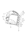
- FIGS. 1 and 2 are perspective views of the bucket 100.
- the bucket 100 includes a bucket body 10 and a plurality of excavation tooth attachments 15.
- the bucket body 10 includes a first side wall 11, a second side wall 12, and a wrapper 13.
- the first side wall 11 and the second side wall 12 face each other.
- Each of the first side wall 11 and the second side wall 12 is a flat plate having a shape surrounded by a substantially arc and a string in a side view.
- the wrapper 13 is a curved plate disposed along a substantially arc of the first side wall 11 and the second side wall 12.
- the wrapper 13 is fixed to the first side wall 11 and the second side wall 12 by welding.
- the wrapper 13 includes a lower edge portion 13a (that is, a bucket tip portion).
- the lower edge portion 13a is generally called a lip.
- the 1st side wall 11, the 2nd side wall 12, and the wrapper 13 form the accommodation space 10V for accommodating earth and sand.
- Each of the plurality of excavation tooth attachment bodies 15 includes an adapter 20, an excavation tooth 30 (hereinafter abbreviated as “tooth”), and a retainer assembly 40.
- the plurality of adapters 20 are fixed to the lower edge portion 13a of the wrapper 13 of the bucket body 10 at a predetermined interval.
- the adapter 20 may be welded to the lower edge portion 13a.
- the adapter 20 that has been worn out due to long-term use is removed from the lower edge portion 13 a and replaced with a new adapter 20.
- the side of the adapter 20 that is fixed to the wrapper 13 is the proximal end of the adapter 20, and the opposite side of the proximal end is the distal end of the adapter 20.
- the tooth 30 is attached to the tip of the adapter 20.
- the tooth 30 has a claw-like outer shape and is formed so as to become gradually thinner toward the tip.
- the cutting edge of the tooth 30 works as a cutting edge during excavation.
- the tooth 30 that has been worn by long-term use is removed from the adapter 20 and replaced with a new tooth 30.
- the side of the tooth 30 with the cutting edge is the tip of the tooth 30, and the side attached to the adapter 20 is the base end of the tooth 30.
- the retainer assembly 40 is used for attaching the tooth 30 to the adapter 20.
- the retainer assembly 40 is accommodated inside the adapter 20 and the tooth 30.
- the worn tooth 30 can be removed from the adapter 20 by disassembling the retainer assembly 40.
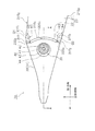
- FIG. 3 is a top view of the tooth attachment 15.
- FIG. 4 is a side view of the tooth attachment 15.
- FIG. 5 is an exploded perspective view of the tooth attachment 15.
- FIG. 6 is a perspective view of the tooth 30.
- first direction A direction extending flatly is referred to as a “second direction”
- second direction a direction orthogonal to the first direction and the second direction
- third direction The second direction of the tooth main body 31 is the width direction of the excavating tooth 30.
- the adapter 20 includes a fixing portion 21 and an insertion portion 22.
- the fixing portion 21 is formed by dividing the proximal end side of the adapter 20 into two.
- the fixing portion 21 sandwiches the lower edge portion 13a of the bucket body 10.
- the fixing portion 21 is fixed to the lower edge portion 13a by welding or the like.
- Fixing unit 21 includes, as shown in FIGS. 3 to 5, the front 21S 1, the upper surface 21S 2, the lower surface 21S 3, a first recess 21T 1, a second recess 21T 2, a.
- the front surface 21S 1 faces the tooth 30 when the tooth 30 is attached to the adapter 20.
- the upper surface 21S 2 continues to the front surface 21S 1 .
- the lower surface 21S 3 continues to the front surface 21S 1 and is provided opposite to the upper surface 21S 2 .
- the first recess 21T 1 is formed on the front surface 21S 1 and the upper surface 21S 2 .
- the first recess 21T 1 is continuous with the front surface 21S 1 and the upper surface 21S 2 and opens.
- a first convex portion 31T 1 of a tooth 30 described later is inserted into the first concave portion 21T 1 .
- the second recess 21T 2 is formed on the front surface 21S 1 and the lower surface 21S 3 .
- the second recess 21T 2 opens to the front surface 21S 1 and the lower surface 21S 3 .
- a second convex portion 31T 2 of a tooth 30 described later is inserted into the second concave portion 21T 2 .
- the first convex portion 31T 1 is inserted into the first concave portion 21T 1 and the second convex portion 31T 2 is inserted into the second concave portion 21T 2 , thereby suppressing the swing of the tooth 30 in the second direction.
- a conventionally well-known tooth that does not include the first convex portion 31T 1 and the second convex portion 31T 2 can be attached to such a fixing portion 21.
- Insertion portion 22 protrudes from the front surface 21S 1 of the fixed portion 21.
- the insertion portion 22 is inserted into an insertion hole 32 (see FIG. 6) of the tooth body 30 described later.
- the insertion portion 22 includes a first side surface 22S 1 , a second side surface 22S 2 , an upper surface 22S 3 , a lower surface 22S 4 , a front end surface 22S 5 , an insertion hole 22a,
- the first side surface 22S 1 and the second side surface 22S 2 are provided on opposite sides.
- the upper surface 22S 3 and the lower surface 22S 4 are provided on opposite sides.
- the distal end surface 22S 5 is continuous with the first side surface 22S 1 , the second side surface 22S 2 , the upper surface 22S 3 and the lower surface 22S 4 .
- the distal end surface 22S 5 is smoothly curved from the upper surface 22S 3 to the lower surface 22S 4 , but is not limited thereto.
- Tip surface 22S 5 may be, for example, flat.
- Insertion hole 22a is an insertion portion 22 penetrates from the first side surface 22S 1 to the second side surface 22S 2. A pin 41 of a retainer assembly 40 to be described later is inserted into the insertion hole 22a.
- FIG. 6 is a view of the tooth 30 as viewed from the base end side.
- the tooth 30 includes a tooth main body 31, an insertion hole 32, a sign pocket 33 (hole), a first extension hole 34, a second extension hole 35, and a first shaft hole. with a 36, and the second shaft hole 37, the first convex portion 31T 1, the second convex portion 31T 2, a.
- the tooth main body 31 is formed in a tapered shape in the second direction and the third direction, as shown in FIGS. 3 and 4. Moreover, the tooth main body 31 is formed in a cup shape as shown in FIG.
- the tooth main body 31 includes a first inner side surface 31S 1 , a second inner side surface 31S 2 , an inner upper surface 31S 3 , an inner lower surface 31S 4, and a rear surface 31S 5 (an example of an outer surface) has a first convex portion 31T 1, the second convex portion 31T 2, a first support portion 101, a second support portion 102, a.
- the first inner side surface 31S 1 faces the first side surface 22S 1 of the insertion portion 22.
- a minute gap may be provided between the first inner side surface 31S 1 and the first side surface 22S 1 .
- the second inner side surface 31S 2 faces the second side surface 22S 2 of the insertion portion 22.
- a minute gap may be provided between the second inner side surface 31S 2 and the second side surface 22S 2 .
- the inner upper surface 31S 3 is in contact with the upper surface 22S 3 of the insertion portion 22.
- the inner and lower surfaces 31S 4 are in contact with the lower surface 22S 4 of the insertion portion 22.
- Rear 31S 5 is a proximal end face of the tooth body 31.
- Rear 31S 5 has an end face of rectangular shape composed of a pair of long sides and a pair of short sides to the outer edge, the insertion hole 32 on the inner side of the end surface is formed.
- the direction of the long side of the rear 31S 5 of tooth 30 (second direction) are substantially parallel to the lower edge portion 13a of the bucket body 10, the direction of the short sides (the third direction) of The direction intersects the lower edge portion 13a.
- the back surface 31S 5 faces the front surface 21S 1 of the fixed portion 21.
- a gap may be provided between the back surface 31S 5 and the front surface 21S 1 .
- a pair of first convex portion 31T 1 second protrusions 31T 2 is formed on each side of the pair of long sides of the rear 31S 5 excavation tooth body 31.
- the first convex portion 31T 1 is a rectangular plate-like portion that is formed so as to protrude from the end surface on the outer edge long side side of the back surface 31S 5 .
- the thickness of the first convex portion 31T 1 is substantially the same as the rear 31S 5.
- the first convex portion 31T 1 is located in the center in the second direction of the outer edge long side end surface of the rear 31S 5.
- the first convex portion 31T 1 is inserted into the first concave portion 21T 1 of the fixed portion 21.
- the second convex portion 31T 2 protrudes from the end surface on the outer edge long side side of the back surface 31S 5 on the opposite side of the first convex portion 31T 1 across the insertion hole 32.
- the second convex portion 31T 2 is inserted into the second concave portion 21T 2 of the fixed portion 21.
- the second convex portion 31T 2 are positioned substantially have the same shape, also the center of the long side end surface and the first convex portion T 1.
- the first convex portion 31T 1 is formed in a tapered shape toward the tip. Therefore, when the first convex portion 31T 1 is cut in the third direction, the cross-sectional shape of the first convex portion 31T 1 is tapered toward the tip.
- the outer peripheral surface Q1 of the first convex portion 31T 1 is separated from the inner bottom surface R1 of the first concave portion 21T 1 . Distance between the inner bottom surface R1 and the outer circumferential surface Q1 is greater extent toward the first distal end side of the convex portion 31T 1. That is, the interval between the inner bottom surface R1 and the outer circumferential surface Q1, the first distal end side of the convex portion 31T 1 is larger than the proximal end side.
- the outer peripheral surface Q1 is spaced from the first recess 21T 1 of the inner surface R2.
- the second convex portion 31T 2 is tapered toward the tip.
- the outer peripheral surface Q2 of the second convex portion 31T 2 is spaced apart from the inner bottom surface R3 of the second recess 21T 2.
- Distance between the inner bottom surface R3 and the outer circumferential surface Q2 is large enough toward the second distal end side of the convex portion 31T 2. That is, the interval between the inner bottom surface R3 and the outer circumferential surface Q2, the tip side of the second convex portion 31T 2 is larger than the proximal end side.
- the outer peripheral surface Q2 is separated from the inside surface R4 of the second concave portion 21T 2.
- the shallowest portion from the base end surface of the tooth main body 31 forms the deepest portion of the insertion hole 32.
- a sign pocket 33 is formed between the first support portion 101 and the second support portion 102.
- the sign pocket 33 is a hole formed at the bottom of the insertion hole 32 and has a width shorter than the width of the bottom of the insertion hole 32 in the longitudinal direction of the tooth body 31.
- the first support portion 101 has a first support surface 101S.
- the first support surface 101 ⁇ / b> S forms part of the bottom surface of the insertion hole 32.
- First supporting surface 101S is opposed to the tip end surface 22S 5 of the insertion portion 22. Between the first supporting surface 101S and the tip surface 22S 5, may be very small gap is provided.
- the second support portion 102 has a second support surface 102S.
- the second support surface 102 ⁇ / b> S forms a part of the bottom surface of the insertion hole 32.
- Second supporting surface 102S is opposed to the tip end surface 22S 5 of the insertion portion 22. Between the second supporting surface 102S and the tip surface 22S 5, it may be very small gap is provided.
- FIG. 7 is a top perspective view of the tooth attachment 15.
- FIG. 7 shows the tooth 30 and the adapter 20 that have been used for a considerable period of time in excavation work.
- an external force F is applied to the tooth 30, and the tooth 30 swings with respect to the adapter 20 in the second direction.
- a first side surface 22S 1 of the first inner surface 31S 1 and the insertion portion 22 of the tooth main body 31 comes into contact at point X.
- the tip surface 22S 5 of the second supporting surface 102S and the insertion portion 22 of the tooth main body 31 comes into contact at point Y.
- the outer peripheral surface Q1 of the first convex portion 31T 1 and the inner side surface R2 of the first concave portion 21T 1 abut at the point Z.
- the second inner side surface 31S 2 of the tooth main body 31 and the second side surface 22S 2 of the insertion portion 22 are separated from each other.
- the tooth 30 inclined with respect to the insertion portion 22 is supported by the adapter 20 at three points.
- the second inner side surface 31S 2 and the second side surface 22S 2 are separated from each other by the outer peripheral surface Q1 coming into contact with the inner side surface R2.
- the point Z at which the outer peripheral surface Q1 contacts the inner side surface R2 is more than the virtual point (between the point X and the point Z) at which the second inner side surface 31S 2 contacts the second side surface 22S 2 in the first direction. Is also spaced from point X. Therefore, the stress applied between the tooth 30 and the adapter 20 can be reduced as compared with the case where the second inner side surface 31S 2 is in contact with the second side surface 22S 2 .
- the second inner side surface 31S 2 of the tooth main body 31 and the second side surface 22S 2 of the insertion portion 22 come into contact with each other.
- a first supporting surface 101S and the tip surface 22S 5 of the insertion portion 22 abuts, the first outer peripheral surface Q1 of the convex portion 31T 1 and the first inner surface of the recess 21T 1 R2 abuts the.
- the first inner side surface 31S 1 of the tooth main body 31 and the first side surface 22S 1 of the insertion portion 22 are separated from each other. Even in this case, the stress applied between the tooth 30 and the adapter 20 can be reduced as described above.
- Insertion holes 32 is formed on the back surface 31S 5 of the tooth main body 31.
- the insertion hole 32 is a hole for inserting the insertion portion 22 of the adapter 20.
- the insertion hole 32 is formed in a tapered shape corresponding to the outer shape of the adapter 20.
- the bottom surfaces of the insertion holes 32 are a first support surface 101S and a second support surface 102S.
- the side surfaces of the insertion hole 32 are a first inner side surface 31S 1 , a second inner side surface 31S 2 , an inner upper surface 31S 3 and an inner lower surface 31S 4 .
- the sign pocket 33 (hole) is formed on the bottom surface of the insertion hole 32 as shown in FIG. That is, the sign pocket 33 is formed so as to be connected to the back of the insertion hole 32.
- the sign pocket 33 is formed between the first support portion 101 and the second support portion 102 of the tooth body 31. In other words, the sign pocket 33 is a gap between the first support part 101 and the second support part 102.
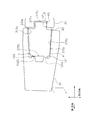
- FIG. 8 is a cross-sectional view taken along the line AA in FIG.
- the tooth 30 and the adapter 20 that have been used for an excavation time are illustrated, and the tooth 30 swings with respect to the adapter 20 in the second direction.
- the sign pocket 33 has a function of accommodating earth and sand that has entered from the gap between the adapter 20 and the tooth 30. Accordingly, it is possible to suppress the intrusion of earth and sand between the adapter 20 and the tooth 30, specifically, between the insertion portion 22 and the first support portion 101 and the second support portion 102.
- the sign pocket 33 suppresses intrusion of earth and sand, wear of the insertion portion of the tooth 30 and the adapter 20 can be suppressed.
- the broken line in FIG. 8 is a wear line that virtually shows how the tooth 30 is worn.
- the distal end of the tooth 30 is worn at a similar speed as a whole.
- the sign pocket 33 is exposed at the tip of the tooth 30.
- the operator recognizes that the signature pocket 33 is exposed at the tip of the tooth 30, that is, confirms that a hole is opened at the tip of the tooth 30, and recognizes that the service life of the tooth 30 is approaching.
- the sign pocket 33 is designed to be exposed before the first extending hole 34 and the second extending hole 35 in a normal use environment. The positional relationship between the sign pocket 33 and the first extending hole 34 and the second extending hole 35 will be described later.
- the first extending hole 34 and the second extending hole 35 are part of the insertion hole 32 (see FIG. 9).
- the first extension hole 34 and the second extension hole 35 are formed on both sides in the second direction of the first support portion 101 and the second support portion 102.
- the first extending hole 34 is formed on the opposite side of the sign pocket 33 across the first support portion 101.
- the second extending hole 35 is formed on the opposite side of the sign pocket 33 across the second support portion 102.
- Each of the first extending hole 34 and the second extending hole 35 is shallower and narrower than the sign pocket 33.
- the first extending hole 34 and the second extending hole 35 are provided so that the corner portions of the adapter 20 (that is, both end portions in the second direction at the tip of the adapter 20) do not hit the inner wall of the insertion hole 32. ing. In particular, even when the tooth 30 is inclined with respect to the adapter 20, it is preferable that the corner portion of the adapter 20 does not hit the inner wall of the tooth 30 (see FIG. 8).
- Each of the first shaft hole 36 and the second shaft hole 37 penetrates the tooth body 31 as shown in FIG.
- Each of the first shaft hole 36 and the second shaft hole 37 is connected to the insertion hole 32.
- the first shaft hole 36 and the second shaft hole 37 are formed in a straight line along the second direction. That is, the first shaft hole 36 and the second shaft hole 37 is formed along the long sides of the outer edge of the rear 31S 5. Therefore, the first shaft hole 36 and the second shaft hole 37 are separated from the first convex portion 31T 1 and the second convex portion 31T 2 .
- the center line AX of the first shaft hole 36 and the second shaft hole 37 is shown by a one-dot chain line. As shown in FIG. 8, both end portions of the retainer assembly 40 are accommodated in the first shaft hole 36 and the second shaft hole 37.
- the retainer assembly 40 includes a pin 41, a bolt 42, a washer 43, and a bush 44.
- the pin 41 is inserted through the insertion hole 22 a of the insertion portion 22.
- the center axis of the pin 41 substantially coincides with the center line AX of the first shaft hole 36 and the second shaft hole 37.
- the bolt 42 is fixed to one end of the pin 41 via a washer 43 and a bush 44.
- the washer 43 and the bush 44 are accommodated inside the first shaft hole 36.
- the tooth 30 With the tooth 30 inserted into the adapter 20, the tooth 30 is held by the adapter 20 by inserting the pin 41 into the insertion hole 22 a of the adapter 20 and assembling the retainer assembly 40.
- the retainer assembly 40 has the above-described configuration, but the retainer assembly of the present invention is not limited to this, and various generally known retainer assemblies can be applied.
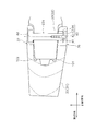
- FIG. 9 is a cross-sectional view taken along the line AA in FIG. However, in FIG. 9, unlike FIG. 8, a state where the tooth 30 does not swing with respect to the adapter 20 in the second direction is illustrated.
- the center position on the center line AX of the first support part 101 and the second support part 102 is shown as a “reference point P”. That is, the reference point P is the center in the second direction of the tooth main body 31 on the center line AX.
- the interval m1 between the reference point P and the deepest part of the sign pocket 33 is larger than the interval m2 between the reference point P and the deepest part of the second extending hole 35.
- the distance between the reference point P and the deepest part of the first extending hole 34 is approximately the same as the distance m2 between the reference point P and the deepest part of the second extending hole 35.
- the deepest part of the first extension hole 34 or the second extension hole 35 is an example of the deepest part of the insertion hole 32.
- the interval m1 is preferably 1.05 times or more of the interval m2, and more preferably 1.10 times or more.
- the minute interval n1 between the distal end of the insertion portion 22 and the first support portion 101 and the second support portion 102 is the center line AX and the first support portion 101 and the second support portion 102.
- the distance n2 is preferably 5% or less, more preferably 2% or less.
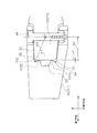
- the adapter 20 includes a first recess 21T 1 formed in the front surface 21S 1, tooth 30 has a first convex portion 31T 1 which is formed on the rear 31S 5.
- the first convex portion 31T 1 is inserted into the first concave portion 21T 1 .
- the outer peripheral surface Q1 of the first convex portion 31T 1 is separated from the inner bottom surface R1 and the inner side surface R2 (an example of the inner surface) of the first concave portion 21T 1 . Accordingly, there are gaps between the outer peripheral surface Q1, the inner bottom surface R1, and the inner side surface R2. Therefore, when the external force F is not acting on the tooth 30, it can suppress that the outer peripheral surface Q1 contact
- the bucket 100 has been described as an example of the excavating tool, but is not limited thereto.
- the excavating tool include a ripper attached to a bulldozer or the like.
- the insertion hole 32 of the tooth 30 decided to have the 1st extension hole 34 and the 2nd extension hole 35, it is not restricted to this. As shown in FIG. 10, the insertion hole 32 may not have the first extension hole 34 and the second extension hole 35. In this case, the corner between the first support portion 101 and the first inner side surface 31S 1 and the corner between the second support portion 102 and the second inner side surface 31S 2 become the deepest portion of the insertion hole 32.
- the tooth main body 31 is set to have a first convex portion 31T 1 and the second convex portion 31T 2 on the end face of the rear 31S 5 long side, but is not limited thereto. Tooth body 31 may not have a first convex portion 31T 1 and the second convex portion 31T 2, may have only one of the first convex portion 31T 1 and the second convex portion 31T 2 . Or you may provide a convex part further in a short side end surface in addition to a long side end surface.
- an excavation tooth attachment body and an excavation tooth that can suppress wear and swinging, which is useful in the field of work machines.
- bucket body 11 first sidewall 12 second sidewall 13 wrapper 15 drilling tooth mounting member 20 adapter 21 fixing portion 21T 1, 21T 2 recesses 22 insertion portion 30 digging tooth 31 drilling tooth body 31T 1, 31T 2 protrusions 31S 5 back 32 Insertion hole 33 Sign pocket (hole) 34, 35 Extension hole 36, 37 Shaft hole 40 Retainer assembly 100 Bucket (excavator) 101 1st support part 102 2nd support part P Reference point
Landscapes
- Engineering & Computer Science (AREA)
- Mining & Mineral Resources (AREA)
- Civil Engineering (AREA)
- General Engineering & Computer Science (AREA)
- Structural Engineering (AREA)
- Component Parts Of Construction Machinery (AREA)
Abstract
Description
上述の通り掘削ツースはその内面が摩耗する。これは、掘削ツースに外力が働いた場合、(i)アダプタと掘削ツースとの間に大きな応力が発生すること、(ii)掘削ツースはアダプタに対しわずかに揺動可能であること、(iii)アダプタと掘削ツースの当接面に土砂等が侵入すること、からアダプタとツースとの当接面が摩耗することに依る。そして、アダプタとツースの当接面が摩耗すれば、ツースが更に揺動しやすくなる。揺動が大きくなると、当接面は更に摩耗しやすくなり、摩耗促進の悪循環が生じる。その結果、部品寿命が短くなる。
(課題を解決するための手段)
本発明の第1態様に係る掘削ツース取付け体は、アダプタと、アダプタに挿入される掘削ツースと、掘削ツースをアダプタに保持させるリテーナアッセンブリと、を備える。アダプタは、掘削ツースと対向する前面と、前面に形成される凹部と、前面から突出する挿入部と、挿入部に形成されリテーナアッセンブリを挿通するための挿通孔と、を有する。掘削ツースは、アダプタの前面と対向する背面と、背面に形成され、凹部に挿入される凸部と、背面に形成され、挿入部が挿入される挿入穴と、挿入穴の両側に形成され、リテーナアッセンブリを挿通するための一対の軸孔と、を有する。背面は、一対の長辺と一対の短辺からなる矩形の外縁を有する。一対の軸孔は、一対の長辺に沿って形成される。凸部の外周面は、外周面に対向する凹部の内底面及び内側面から離間している。
(発明の効果)
本発明によれば、摩耗や揺動を抑制可能な掘削ツース取付け体及び掘削ツースを提供することができる。
図1及び図2は、バケット100の斜視図である。図1及び図2に示すように、バケット100は、バケット本体10と、複数の掘削ツース取付け体15と、を備える。
図3は、ツース取付け体15の上面図である。図4は、ツース取付け体15の側面図である。図5は、ツース取付け体15の分解斜視図である。図6は、ツース30の斜視図である。なお、以下の説明では、図3及び図4に示すように、ツース本体31が延びる方向(すなわち、ツース30の基端と先端を結ぶ方向)を“第1方向”と称し、ツース本体31が平たく延びる方向を“第2方向”と称し、第1方向と第2方向に直交する方向を“第3方向”と称する。ツース本体31の第2方向が、掘削ツース30の幅方向となる。
次に、アダプタ20とツース30の位置関係について、図面を参照しながら説明する。図9は、図4のA-A断面図である。ただし、図9では、図8と異なり、第2方向においてツース30がアダプタ20に対して揺動していない状態が図示されている。
(1)アダプタ20は、前面21S1に形成される第1凹部21T1を有し、ツース30は、背面31S5に形成される第1凸部31T1を有する。第1凸部31T1は、第1凹部21T1に挿入される。
本発明は以上のような実施形態に限定されるものではなく、本発明の範囲を逸脱することなく種々の変形又は修正が可能である。
11 第1側壁
12 第2側壁
13 ラッパー
15 掘削ツース取付け体
20 アダプタ
21 固定部
21T1,21T2 凹部
22 挿入部
30 掘削ツース
31 掘削ツース本体
31T1、31T2 凸部
31S5 背面
32 挿入穴
33 サインポケット(穴部)
34,35 延在穴
36,37 軸孔
40 リテーナアッセンブリ
100 バケット(掘削具)
101 第1の支持部
102 第2の支持部
P 基準点
Claims (8)
- アダプタと、
前記アダプタに挿入される掘削ツースと、
前記掘削ツースを前記アダプタに保持させるリテーナアッセンブリと、
を備え、
前記アダプタは、前記掘削ツースと対向する前面と、前記前面に形成される凹部と、前記前面から突出する挿入部と、前記挿入部に形成され前記リテーナアッセンブリを挿通するための挿通孔と、を有し、
前記掘削ツースは、前記アダプタの前記前面と対向する背面と、前記背面に形成され前記凹部に挿入される凸部と、前記背面に形成され前記挿入部が挿入される挿入穴と、前記挿入穴の両側に形成され前記リテーナアッセンブリを挿通するための一対の軸孔と、を有し、
前記背面は、一対の長辺と一対の短辺からなる矩形の外縁を有し、
前記一対の軸孔は、前記一対の長辺に沿って形成されており、
前記凸部の外周面は、前記外周面に対向する前記凹部の内底面及び内側面から離間している、
掘削ツース取付け体。 - 前記凹部の前記内底面と前記凸部の前記外周面との間隔は、前記凸部の先端側に向かうほど大きい、
請求項1に記載の掘削ツース取付け体 - 前記凸部は前記背面の前記長辺の側に形成される、
請求項1又は2に記載の掘削ツース取付け体。 - 前記凸部は、前記一対の軸孔から離間している、
請求項1乃至3のいずれかに記載の掘削ツース取付け体。 - リテーナアッセンブリによってアダプタに保持される掘削ツースであって、
一対の長辺と一対の短辺からなる矩形の外縁を有する背面を持つ掘削ツース本体と、
前記掘削ツース本体の背面の前記一対の長辺の側に形成される凸部と、
前記背面に形成され前記アダプタが挿入される挿入穴と、
前記挿入穴の両側に形成され、前記リテーナアッセンブリを挿通するための一対の軸孔と、
を備え、
前記凸部は、先細の断面形状を有し、
前記一対の軸孔は、前記一対の長辺に沿って形成されている、
掘削ツース。 - 前記凸部は、前記一対の軸孔から離間している、
請求項5に記載の掘削ツース。 - 前記凸部は前記掘削ツース本体の前記背面の前記長辺の側の中心に形成される、
請求項5又は6に記載の掘削ツース。 - 前記挿入穴の底部に設けられ、前記挿入穴の前記底部の幅より短い幅を有する穴部を、更に備える、
請求項5乃至7のいずれかに記載の掘削ツース。
Priority Applications (6)
| Application Number | Priority Date | Filing Date | Title |
|---|---|---|---|
| JP2014525233A JP5701455B2 (ja) | 2012-12-18 | 2013-12-17 | 掘削ツース取付け体及び掘削ツース |
| DE112013001664.8T DE112013001664B4 (de) | 2012-12-18 | 2013-12-17 | Befestigungsanordnung für einen Grabzahn und Grabzahn |
| IN1533DEN2015 IN2015DN01533A (ja) | 2012-12-18 | 2013-12-17 | |
| KR1020157006305A KR101718774B1 (ko) | 2012-12-18 | 2013-12-17 | 굴삭 투스 장착체 및 굴삭 투스 |
| CN201380009172.9A CN104160098B (zh) | 2012-12-18 | 2013-12-17 | 挖掘齿安装体及挖掘齿 |
| US14/379,578 US9617718B2 (en) | 2012-12-18 | 2013-12-17 | Digging tooth mounting assembly and digging tooth |
Applications Claiming Priority (2)
| Application Number | Priority Date | Filing Date | Title |
|---|---|---|---|
| JP2012-275320 | 2012-12-18 | ||
| JP2012275320 | 2012-12-18 |
Publications (1)
| Publication Number | Publication Date |
|---|---|
| WO2014098057A1 true WO2014098057A1 (ja) | 2014-06-26 |
Family
ID=50978384
Family Applications (1)
| Application Number | Title | Priority Date | Filing Date |
|---|---|---|---|
| PCT/JP2013/083691 Ceased WO2014098057A1 (ja) | 2012-12-18 | 2013-12-17 | 掘削ツース取付け体及び掘削ツース |
Country Status (7)
| Country | Link |
|---|---|
| US (1) | US9617718B2 (ja) |
| JP (1) | JP5701455B2 (ja) |
| KR (1) | KR101718774B1 (ja) |
| CN (1) | CN104160098B (ja) |
| DE (1) | DE112013001664B4 (ja) |
| IN (1) | IN2015DN01533A (ja) |
| WO (1) | WO2014098057A1 (ja) |
Families Citing this family (12)
| Publication number | Priority date | Publication date | Assignee | Title |
|---|---|---|---|---|
| JP5885648B2 (ja) | 2012-12-18 | 2016-03-15 | 株式会社小松製作所 | 掘削ツース及び掘削具 |
| US9441351B2 (en) * | 2013-08-01 | 2016-09-13 | Caterpillar Inc. | Ground engaging tool assembly |
| US9441349B2 (en) * | 2013-08-01 | 2016-09-13 | Caterpillar Inc. | Ground engaging tool assembly |
| US9290914B2 (en) * | 2013-08-01 | 2016-03-22 | Caterpillar Inc. | Ground engaging tool assembly |
| BR112018016138B1 (pt) * | 2016-02-08 | 2022-11-16 | Esco Group Llc | Conjunto de desgaste para equipamento de trabalho na terra |
| US10494793B2 (en) | 2016-12-15 | 2019-12-03 | Caterpillar Inc. | Implement tip assembly having tip with support rib |
| US10480161B2 (en) | 2016-12-15 | 2019-11-19 | Caterpillar Inc. | Implement tip assembly having tip with wear indicator |
| US10480162B2 (en) | 2016-12-15 | 2019-11-19 | Caterpillar Inc. | Implement ground engaging tip assembly having tip with tapered retention channel |
| CA3120898C (en) | 2018-11-23 | 2024-06-11 | Torsch Inc. | Sleeve valve |
| USD894971S1 (en) | 2019-04-26 | 2020-09-01 | Caterpillar Inc. | Tip for a ground engaging machine implement |
| JP7197450B2 (ja) * | 2019-09-13 | 2022-12-27 | 株式会社小松製作所 | バケット用のツースアダプタ、バケット用のツース取付構造、及びバケット |
| US20250092645A1 (en) * | 2021-06-04 | 2025-03-20 | Talon Engineering Sdn. Bhd | Attachment of a wear member |
Citations (4)
| Publication number | Priority date | Publication date | Assignee | Title |
|---|---|---|---|---|
| JPS6076149U (ja) * | 1983-10-28 | 1985-05-28 | 株式会社小松製作所 | バケツトツ−スのポイント取付装置 |
| US6477796B1 (en) * | 2000-07-06 | 2002-11-12 | Caterpillar Inc | Tooth assembly for implements |
| US20110000109A1 (en) * | 2008-02-08 | 2011-01-06 | Cqms Razer (Usa) Llc | Excavation retention assembly |
| JP2011099322A (ja) * | 2003-04-30 | 2011-05-19 | Esco Corp | 解放自在のカップリングアッセンブリ |
Family Cites Families (25)
| Publication number | Priority date | Publication date | Assignee | Title |
|---|---|---|---|---|
| US1808311A (en) * | 1929-09-11 | 1931-06-02 | Sabby Madonna | Excavator |
| US3012346A (en) * | 1958-09-15 | 1961-12-12 | Esco Corp | Excavating tooth and base support therefor |
| US3197894A (en) * | 1962-07-26 | 1965-08-03 | American Brake Shoe Co | Digging tooth with screws set into resilient pockets |
| US3191323A (en) * | 1962-08-13 | 1965-06-29 | American Brake Shoe Co | Digging tooth with nut and bolt connecting means |
| US3277592A (en) * | 1963-09-17 | 1966-10-11 | Richard L Launder | Reinforced replaceable tooth for digging machines |
| US4577423A (en) * | 1984-12-24 | 1986-03-25 | Esco Corporation | Excavating tooth system |
| US5144762A (en) * | 1990-04-16 | 1992-09-08 | Gh Hensley Industries, Inc. | Wear indicating and tooth stabilizing systems for excavating tooth and adapter assemblies |
| US5068986A (en) * | 1990-08-30 | 1991-12-03 | Esco Corporation | Excavating tooth point particularly suited for large dragline buckets |
| US5423138A (en) * | 1994-04-04 | 1995-06-13 | Caterpillar, Inc. | Tip to adapter interface |
| US5987787A (en) * | 1998-02-11 | 1999-11-23 | Wright Equipment Company (Proprietary) Limited | Ground engaging tool components |
| US6374521B1 (en) * | 1999-04-05 | 2002-04-23 | Trn Business Trust | Apparatus and method for coupling an excavation tooth assembly |
| FR2792343B1 (fr) * | 1999-04-19 | 2001-06-22 | Charles Pasqualini | Dispositif de liaison entre des pieces d'usure aux extremites d'outils et receptacles en usage sur les engins et materiels de travaux publics |
| CA2312550C (en) * | 2000-06-27 | 2010-01-05 | Quality Steel Foundries Ltd. | Torque locking system for fastening a wear member to a support structure |
| AR046804A1 (es) | 2003-04-30 | 2005-12-28 | Esco Corp | Conjunto de acoplamiento desenganchable para pala de excavadora |
| US7036249B2 (en) * | 2003-05-22 | 2006-05-02 | Trn Business Trust | Tooth adapter having an elastomeric clamp assembly and method for using same |
| CA2443168A1 (en) * | 2003-09-26 | 2004-10-26 | Quality Steel Foundries Ltd. | Insert for locking mechanism for ground engaging tools |
| US7032334B2 (en) * | 2004-05-28 | 2006-04-25 | Trn Business Trust | System and method for coupling excavation equipment components |
| US7523572B2 (en) * | 2004-12-02 | 2009-04-28 | Predac | Assembly for coupling wear parts to support tools for heavy-construction machinery |
| US7788830B2 (en) * | 2008-02-08 | 2010-09-07 | Cqms Razer (Usa) Llc | Excavation retention assembly |
| US20110058894A1 (en) * | 2008-04-18 | 2011-03-10 | Cqms Pty Ltd | A lock assembly for an excavator wear member |
| WO2010065982A1 (en) * | 2008-12-10 | 2010-06-17 | Cqms Pty Ltd | A lock for an excavator wear assembly |
| CN102510923B (zh) * | 2010-03-31 | 2013-11-13 | 株式会社小松制作所 | 工作装置以及安装销组件 |
| JP2011246974A (ja) * | 2010-05-27 | 2011-12-08 | Komatsu Ltd | 作業機および取付けピン組立て体 |
| KR101941601B1 (ko) * | 2011-10-20 | 2019-01-23 | 트리티니인더스트리이즈인코포레이티드 | 희토류 재료를 갖춘 굴착 장치용 치형 조립체 |
| JP5885648B2 (ja) * | 2012-12-18 | 2016-03-15 | 株式会社小松製作所 | 掘削ツース及び掘削具 |
-
2013
- 2013-12-17 WO PCT/JP2013/083691 patent/WO2014098057A1/ja not_active Ceased
- 2013-12-17 IN IN1533DEN2015 patent/IN2015DN01533A/en unknown
- 2013-12-17 DE DE112013001664.8T patent/DE112013001664B4/de not_active Expired - Fee Related
- 2013-12-17 KR KR1020157006305A patent/KR101718774B1/ko not_active Expired - Fee Related
- 2013-12-17 JP JP2014525233A patent/JP5701455B2/ja not_active Expired - Fee Related
- 2013-12-17 CN CN201380009172.9A patent/CN104160098B/zh not_active Expired - Fee Related
- 2013-12-17 US US14/379,578 patent/US9617718B2/en not_active Expired - Fee Related
Patent Citations (4)
| Publication number | Priority date | Publication date | Assignee | Title |
|---|---|---|---|---|
| JPS6076149U (ja) * | 1983-10-28 | 1985-05-28 | 株式会社小松製作所 | バケツトツ−スのポイント取付装置 |
| US6477796B1 (en) * | 2000-07-06 | 2002-11-12 | Caterpillar Inc | Tooth assembly for implements |
| JP2011099322A (ja) * | 2003-04-30 | 2011-05-19 | Esco Corp | 解放自在のカップリングアッセンブリ |
| US20110000109A1 (en) * | 2008-02-08 | 2011-01-06 | Cqms Razer (Usa) Llc | Excavation retention assembly |
Also Published As
| Publication number | Publication date |
|---|---|
| JP5701455B2 (ja) | 2015-04-15 |
| US20150013198A1 (en) | 2015-01-15 |
| KR20150038642A (ko) | 2015-04-08 |
| CN104160098A (zh) | 2014-11-19 |
| CN104160098B (zh) | 2017-09-01 |
| IN2015DN01533A (ja) | 2015-07-03 |
| DE112013001664T5 (de) | 2014-12-18 |
| JPWO2014098057A1 (ja) | 2017-01-12 |
| DE112013001664B4 (de) | 2020-09-24 |
| US9617718B2 (en) | 2017-04-11 |
| KR101718774B1 (ko) | 2017-03-22 |
Similar Documents
| Publication | Publication Date | Title |
|---|---|---|
| JP5701455B2 (ja) | 掘削ツース取付け体及び掘削ツース | |
| JP5885648B2 (ja) | 掘削ツース及び掘削具 | |
| ES2759935T3 (es) | Sistema de refuerzo mejorado para un adaptador de herramientas | |
| JP5362074B2 (ja) | 建設機械の掘削バケット | |
| AU2014296579B2 (en) | Ground engaging tool assembly | |
| CN110073062A (zh) | 具有带有锥形固位通道的尖端的器具地面接合尖端组件 | |
| JP5373169B1 (ja) | 掘削爪および掘削爪用ボディ | |
| CN110073063A (zh) | 具有带有支承肋部的末端的器具末端组件 | |
| CN106687646A (zh) | 机具切割边缘磨损构件 | |
| JP5318993B1 (ja) | 建設機械の掘削バケット | |
| CN106715805A (zh) | 机具磨损构件 | |
| US20150013197A1 (en) | Wear collar for tool retention system | |
| CN106715804A (zh) | 机具端部刀头磨损构件 | |
| BR112019012191B1 (pt) | Ponta de engate ao solo | |
| JP2023001280A (ja) | バケット用のツースアダプタ、バケット用のツース取付構造、及びバケット | |
| CN104024542B (zh) | 挖掘斗齿及挖掘工具 | |
| AU2012268793B2 (en) | Ground engaging tools | |
| JP5877430B1 (ja) | ツース盤 | |
| JP6166121B2 (ja) | バケット先端の隠蔽用アダプタ及び掘削等を行う作業機械に取り付けられるバケット | |
| AU2014101036A4 (en) | Ground Engaging Tools | |
| JP2005171612A (ja) | 建設機械の掘削用ツース | |
| JP2006045769A (ja) | 掘削用バケット |
Legal Events
| Date | Code | Title | Description |
|---|---|---|---|
| ENP | Entry into the national phase |
Ref document number: 2014525233 Country of ref document: JP Kind code of ref document: A |
|
| WWE | Wipo information: entry into national phase |
Ref document number: 14379578 Country of ref document: US |
|
| 121 | Ep: the epo has been informed by wipo that ep was designated in this application |
Ref document number: 13865913 Country of ref document: EP Kind code of ref document: A1 |
|
| WWE | Wipo information: entry into national phase |
Ref document number: 1120130016648 Country of ref document: DE Ref document number: 112013001664 Country of ref document: DE |
|
| ENP | Entry into the national phase |
Ref document number: 20157006305 Country of ref document: KR Kind code of ref document: A |
|
| 122 | Ep: pct application non-entry in european phase |
Ref document number: 13865913 Country of ref document: EP Kind code of ref document: A1 |