WO2014091852A1 - 半導体チップ温度推定装置及び過熱保護装置 - Google Patents
半導体チップ温度推定装置及び過熱保護装置 Download PDFInfo
- Publication number
- WO2014091852A1 WO2014091852A1 PCT/JP2013/080409 JP2013080409W WO2014091852A1 WO 2014091852 A1 WO2014091852 A1 WO 2014091852A1 JP 2013080409 W JP2013080409 W JP 2013080409W WO 2014091852 A1 WO2014091852 A1 WO 2014091852A1
- Authority
- WO
- WIPO (PCT)
- Prior art keywords
- temperature
- semiconductor chip
- estimation
- estimated
- semiconductor
- Prior art date
- Legal status (The legal status is an assumption and is not a legal conclusion. Google has not performed a legal analysis and makes no representation as to the accuracy of the status listed.)
- Ceased
Links
Images



Classifications
-
- G—PHYSICS
- G01—MEASURING; TESTING
- G01K—MEASURING TEMPERATURE; MEASURING QUANTITY OF HEAT; THERMALLY-SENSITIVE ELEMENTS NOT OTHERWISE PROVIDED FOR
- G01K1/00—Details of thermometers not specially adapted for particular types of thermometer
- G01K1/08—Protective devices, e.g. casings
- G01K1/12—Protective devices, e.g. casings for preventing damage due to heat overloading
-
- G—PHYSICS
- G01—MEASURING; TESTING
- G01K—MEASURING TEMPERATURE; MEASURING QUANTITY OF HEAT; THERMALLY-SENSITIVE ELEMENTS NOT OTHERWISE PROVIDED FOR
- G01K7/00—Measuring temperature based on the use of electric or magnetic elements directly sensitive to heat ; Power supply therefor, e.g. using thermoelectric elements
- G01K7/16—Measuring temperature based on the use of electric or magnetic elements directly sensitive to heat ; Power supply therefor, e.g. using thermoelectric elements using resistive elements
-
- G—PHYSICS
- G01—MEASURING; TESTING
- G01K—MEASURING TEMPERATURE; MEASURING QUANTITY OF HEAT; THERMALLY-SENSITIVE ELEMENTS NOT OTHERWISE PROVIDED FOR
- G01K7/00—Measuring temperature based on the use of electric or magnetic elements directly sensitive to heat ; Power supply therefor, e.g. using thermoelectric elements
- G01K7/16—Measuring temperature based on the use of electric or magnetic elements directly sensitive to heat ; Power supply therefor, e.g. using thermoelectric elements using resistive elements
- G01K7/22—Measuring temperature based on the use of electric or magnetic elements directly sensitive to heat ; Power supply therefor, e.g. using thermoelectric elements using resistive elements the element being a non-linear resistance, e.g. thermistor
-
- G—PHYSICS
- G01—MEASURING; TESTING
- G01K—MEASURING TEMPERATURE; MEASURING QUANTITY OF HEAT; THERMALLY-SENSITIVE ELEMENTS NOT OTHERWISE PROVIDED FOR
- G01K7/00—Measuring temperature based on the use of electric or magnetic elements directly sensitive to heat ; Power supply therefor, e.g. using thermoelectric elements
- G01K7/42—Circuits effecting compensation of thermal inertia; Circuits for predicting the stationary value of a temperature
-
- H—ELECTRICITY
- H02—GENERATION; CONVERSION OR DISTRIBUTION OF ELECTRIC POWER
- H02M—APPARATUS FOR CONVERSION BETWEEN AC AND AC, BETWEEN AC AND DC, OR BETWEEN DC AND DC, AND FOR USE WITH MAINS OR SIMILAR POWER SUPPLY SYSTEMS; CONVERSION OF DC OR AC INPUT POWER INTO SURGE OUTPUT POWER; CONTROL OR REGULATION THEREOF
- H02M1/00—Details of apparatus for conversion
- H02M1/32—Means for protecting converters other than automatic disconnection
-
- H—ELECTRICITY
- H02—GENERATION; CONVERSION OR DISTRIBUTION OF ELECTRIC POWER
- H02P—CONTROL OR REGULATION OF ELECTRIC MOTORS, ELECTRIC GENERATORS OR DYNAMO-ELECTRIC CONVERTERS; CONTROLLING TRANSFORMERS, REACTORS OR CHOKE COILS
- H02P29/00—Arrangements for regulating or controlling electric motors, appropriate for both AC and DC motors
- H02P29/60—Controlling or determining the temperature of the motor or of the drive
- H02P29/68—Controlling or determining the temperature of the motor or of the drive based on the temperature of a drive component or a semiconductor component
-
- H—ELECTRICITY
- H02—GENERATION; CONVERSION OR DISTRIBUTION OF ELECTRIC POWER
- H02H—EMERGENCY PROTECTIVE CIRCUIT ARRANGEMENTS
- H02H7/00—Emergency protective circuit arrangements specially adapted for specific types of electric machines or apparatus or for sectionalised protection of cable or line systems, and effecting automatic switching in the event of an undesired change from normal working conditions
- H02H7/10—Emergency protective circuit arrangements specially adapted for specific types of electric machines or apparatus or for sectionalised protection of cable or line systems, and effecting automatic switching in the event of an undesired change from normal working conditions for converters; for rectifiers
- H02H7/12—Emergency protective circuit arrangements specially adapted for specific types of electric machines or apparatus or for sectionalised protection of cable or line systems, and effecting automatic switching in the event of an undesired change from normal working conditions for converters; for rectifiers for static converters or rectifiers
-
- H—ELECTRICITY
- H02—GENERATION; CONVERSION OR DISTRIBUTION OF ELECTRIC POWER
- H02M—APPARATUS FOR CONVERSION BETWEEN AC AND AC, BETWEEN AC AND DC, OR BETWEEN DC AND DC, AND FOR USE WITH MAINS OR SIMILAR POWER SUPPLY SYSTEMS; CONVERSION OF DC OR AC INPUT POWER INTO SURGE OUTPUT POWER; CONTROL OR REGULATION THEREOF
- H02M1/00—Details of apparatus for conversion
- H02M1/32—Means for protecting converters other than automatic disconnection
- H02M1/327—Means for protecting converters other than automatic disconnection against abnormal temperatures
-
- H—ELECTRICITY
- H02—GENERATION; CONVERSION OR DISTRIBUTION OF ELECTRIC POWER
- H02M—APPARATUS FOR CONVERSION BETWEEN AC AND AC, BETWEEN AC AND DC, OR BETWEEN DC AND DC, AND FOR USE WITH MAINS OR SIMILAR POWER SUPPLY SYSTEMS; CONVERSION OF DC OR AC INPUT POWER INTO SURGE OUTPUT POWER; CONTROL OR REGULATION THEREOF
- H02M7/00—Conversion of AC power input into DC power output; Conversion of DC power input into AC power output
- H02M7/42—Conversion of DC power input into AC power output without possibility of reversal
- H02M7/44—Conversion of DC power input into AC power output without possibility of reversal by static converters
- H02M7/48—Conversion of DC power input into AC power output without possibility of reversal by static converters using discharge tubes with control electrode or semiconductor devices with control electrode
- H02M7/53—Conversion of DC power input into AC power output without possibility of reversal by static converters using discharge tubes with control electrode or semiconductor devices with control electrode using devices of a triode or transistor type requiring continuous application of a control signal
- H02M7/537—Conversion of DC power input into AC power output without possibility of reversal by static converters using discharge tubes with control electrode or semiconductor devices with control electrode using devices of a triode or transistor type requiring continuous application of a control signal using semiconductor devices only, e.g. single switched pulse inverters
- H02M7/5387—Conversion of DC power input into AC power output without possibility of reversal by static converters using discharge tubes with control electrode or semiconductor devices with control electrode using devices of a triode or transistor type requiring continuous application of a control signal using semiconductor devices only, e.g. single switched pulse inverters in a bridge configuration
-
- H—ELECTRICITY
- H10—SEMICONDUCTOR DEVICES; ELECTRIC SOLID-STATE DEVICES NOT OTHERWISE PROVIDED FOR
- H10D—INORGANIC ELECTRIC SEMICONDUCTOR DEVICES
- H10D89/00—Aspects of integrated devices not covered by groups H10D84/00 - H10D88/00
- H10D89/60—Integrated devices comprising arrangements for electrical or thermal protection, e.g. protection circuits against electrostatic discharge [ESD]
Definitions
- the present invention relates to, for example, a temperature estimation device for a semiconductor chip constituting a semiconductor module, and an overheat protection device for protecting a power converter from an overheat accident using the temperature estimation device.
- FIG. 7 is a block diagram showing the prior art described in Patent Document 1.
- 101 is a rectifier circuit connected to a three-phase AC power source (not shown)
- 102 is a smoothing capacitor
- 103 is a heat sink in which an inverter 104 and a thermistor 105 are installed
- 106 is a motor driven by the inverter 104.
- 200 is a control device that controls the semiconductor switching element of the inverter 104
- 201 and 202 are first and second set temperatures
- 203 is a current detector
- 204 and 205 are comparators
- 206 is a current cutoff function
- 207 is current.
- 208 is a PWM control unit
- 209 is a temperature detection unit
- 210 is a T j (junction temperature) estimation unit.
- the temperature detection value of the heat sink 103 obtained by the thermistor 105 and the temperature detection unit 209, the current detection value of the motor 106 by the current detector 203, and the drive signal (carrier frequency) by the PWM control unit 208 are estimated as T j.
- the T j estimating unit 210 obtains a temperature rise corresponding to the conduction loss and the switching loss based on the current detection value and the drive signal, and adds this temperature rise to the temperature detection value of the heat sink 103 to obtain the temperature of the semiconductor switching element.
- Junction temperature semiconductor chip temperature
- the current of the inverter 104 is limited by the current limiting function 207, and the second set temperature 202 is higher than the first set temperature 201. If it exceeds, the current interruption function 206 interrupts the current of the inverter 104 to realize overheat protection.
- Patent Document 2 discloses a control device for a power converter that limits the output current of the inverter so that the estimated semiconductor chip temperature does not exceed the allowable value when the synchronous motor enters a stalled state. ing.
- FIG. 8 is a conceptual diagram showing the temperature estimation function of the semiconductor chip in the T j estimation unit 210 of FIG. 7, where 210a is a temperature rise estimation unit, 210b is an addition / subtraction unit, 210c is a semiconductor chip loss calculation unit, and 210d is a semiconductor. This is a chip temperature rise calculation unit.
- the T j estimation unit 210 outputs an added value of the estimated temperature rise value due to the loss of the semiconductor chip and the temperature detection value by the thermistor 105 as the estimated temperature value of the semiconductor chip.
- Japanese Patent No. 3075303 (paragraph [0006], FIG. 1 etc.)
- Japanese Patent Laying-Open No. 2005-124387 (paragraphs [0021] to [0030], FIG. 1 etc.)
- Patent Documents 1 and 2 are based on the premise that a cooling body temperature or a refrigerant temperature that is a reference temperature for estimating a semiconductor chip temperature is detected.
- a temperature sensor such as a thermistor is installed in the cooling body.
- a method of estimating the temperature of a cooling body or the like with a thermistor built in a semiconductor module without installing a thermistor separately in the cooling body or the like by incorporating a thermistor in a semiconductor module composed of a plurality of semiconductor chips is.
- the thermistor may not be able to accurately estimate the temperature of the cooling body or the like due to the influence of heat generated by the semiconductor chip near the thermistor.
- the problem to be solved by the present invention is that even when a semiconductor chip in the vicinity of a temperature sensor such as a thermistor generates heat, a cooling body or a refrigerant (hereinafter collectively referred to as “cooling element”) that serves as a base temperature for estimating the semiconductor chip temperature.
- a semiconductor chip temperature estimation device that eliminates the need for a temperature sensor for detecting the temperature of the cooling element and reduces the cost and size of the power converter.
- Another object of the present invention is to provide an overheat protection device that protects a semiconductor chip and a power converter from an overheat accident by a current limiting operation based on an estimated value of the semiconductor chip temperature.
- a semiconductor chip temperature estimation device of the present invention relates to a semiconductor chip temperature estimation device that estimates the temperature of a semiconductor chip built in a semiconductor module together with a temperature sensor such as a thermistor.
- a semiconductor chip temperature estimation device includes first estimation means for estimating a loss of a semiconductor chip by calculation using at least a current and a switching frequency of a semiconductor switching element in the semiconductor chip, A storage means in which a correlation between a temperature rise value which is a difference between a temperature detection value by a temperature sensor and a temperature of a cooling element such as a refrigerant or a cooling body for cooling the semiconductor module and a loss of the semiconductor chip is stored in advance; , Second estimation means for estimating the temperature rise of the temperature sensor using the estimated loss value of the semiconductor chip output from the first estimation means and the correlation; A third estimation means for subtracting the temperature rise estimated value of the temperature sensor output from the second estimation means from the temperature detection value by the temperature sensor to estimate the cooling element temperature, The temperature estimation means for estimating a temperature rise value which
- the semiconductor chip temperature estimation apparatus is characterized in that the correlation in claim 1 approximates the relationship between the temperature rise of the temperature sensor and the loss of the semiconductor chip by a first order lag element. To do.
- a semiconductor chip temperature estimation device wherein the first estimation unit, the storage unit, and the second estimation unit according to the first aspect are provided corresponding to a plurality of semiconductor chips, respectively.
- the cooling element temperature is estimated by subtracting the sum of the temperature rise estimated values output from the plurality of second estimating means from the temperature detection value by the temperature sensor.
- the semiconductor chip temperature estimating apparatus wherein the correlation in the first aspect approximates the relationship between the temperature rise of the temperature sensor and the loss of the semiconductor chip by the sum of a plurality of first-order lag elements. It is characterized by that.
- a semiconductor chip temperature estimation device is the semiconductor chip temperature estimation device according to any one of claims 1 to 4, further comprising fourth estimation means for estimating a temperature rise of the semiconductor chip by calculation.
- the semiconductor chip temperature estimated value output from the fourth estimating means and the cooling element temperature estimated value output from the third estimating means are added to obtain the semiconductor chip temperature estimated value.
- the semiconductor chip temperature estimation device according to the fifth aspect, wherein the fourth estimation means in the fifth aspect estimates the loss of the semiconductor chip by calculation using at least the current and switching frequency of the semiconductor switching element in the semiconductor chip. And 6th estimation means for estimating the temperature rise of the semiconductor chip by calculation using the estimated loss value of the semiconductor chip output from the fifth estimation means. .
- the semiconductor chip temperature estimation device is the semiconductor chip temperature estimation device according to any one of claims 1 to 4, wherein the cooling element is a refrigerant that cools the semiconductor module. To do.
- An overheat protection device provides a semiconductor chip in which the estimated temperature of the semiconductor chip output from the estimated temperature of the semiconductor chip according to any one of the first to fourth aspects exceeds a set value. Means for limiting the current flowing through the semiconductor switching element by controlling the operation of the semiconductor switching element is provided.
- the present invention it is possible to estimate the cooling element temperature without separately installing a temperature sensor such as a thermistor on a cooling element such as a refrigerant or a cooling body. For this reason, it is possible to reduce the number of parts and achieve downsizing and cost reduction of the power converter. Even if the temperature sensor is affected by the heat generated by a nearby semiconductor chip, the temperature of the cooling element can be estimated with high accuracy by subtracting the temperature rise based on the predetermined correlation from the temperature detection value by the temperature sensor. Can do. As described above, since the reliability of the cooling element temperature estimation value is high in the present invention, the reliability of the semiconductor chip temperature estimation value based on the cooling element temperature estimation value is also high, and the reliability of the semiconductor chip and the power converter is increased. Overheat protection can be performed safely and reliably.
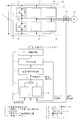
- FIG. 1 shows the principal part of the 1st Example of the semiconductor chip temperature estimation apparatus in embodiment. It is a block diagram which shows the principal part of 2nd Example of the semiconductor chip temperature estimation apparatus in embodiment. It is a block diagram which shows the principal part of 3rd Example of the semiconductor chip temperature estimation apparatus in embodiment. It is a block diagram which shows the principal part of the 4th Example of the semiconductor chip temperature estimation apparatus in embodiment. It is a block diagram which shows the 5th Example of the semiconductor chip temperature estimation apparatus in embodiment. It is a block diagram of the prior art described in patent document 1. FIG. It is a conceptual diagram which shows the temperature estimation function of the semiconductor chip in the Tj estimation part of FIG.
- FIG. 1 is a block diagram of a power conversion device to which an embodiment of the present invention is applied.
- This power converter is composed of a main circuit that drives a motor by a power converter composed of a three-phase inverter, and a control device for the inverter.
- 10 is a smoothing capacitor to which a DC voltage is applied
- 11 to 16 are semiconductor switching elements such as IGBTs and other semiconductor switching elements
- a semiconductor chip comprising a free-wheeling diode 17 is a thermistor as a temperature sensor
- 18 is a semiconductor module
- 20 is a motor which is a load of the inverter
- 21 is a heat sink for cooling the semiconductor chips 11-16.
- the type and number of semiconductor switching elements, the type of power converter, and the number of phases are not particularly limited.
- the control device estimates the temperature of the semiconductor chip of the present embodiment, in which the temperature detection value from the thermistor 17, the current detection value of the motor 20 by the current detector 19, and the carrier frequency from the PWM circuit 8 described later are input. It has a device 6.
- the semiconductor chip temperature estimation device 6 includes a cooling element temperature estimation unit 1, a semiconductor chip temperature increase estimation unit 4, and an addition / subtraction means 5 that adds the outputs of both, and outputs from the semiconductor chip temperature estimation device 6.
- the estimated semiconductor chip temperature is input to the current limit command circuit 7.
- the current limit command circuit 7 generates a current limit command for limiting the current flowing through the semiconductor switching element (inverter output current) when the estimated semiconductor chip temperature exceeds the set value.
- the current limit command includes a command to limit the current to zero (turn off the semiconductor switching element).
- the current limit command is input to the PWM circuit 8.
- the PWM circuit 8 generates a PWM signal based on a voltage command from a control circuit (not shown) and outputs the PWM signal to the subsequent gate drive circuit 9.
- the gate drive circuit 9 generates a gate signal and turns on and off the semiconductor switching elements in the semiconductor chips 11 to 16, thereby causing the motor 20 to supply three-phase AC power by the DC / AC conversion operation of the inverter composed of the semiconductor chips 11 to 16. Supply.
- the cooling element for cooling the semiconductor module 18 in FIG. 1 is a refrigerant such as water for forcibly cooling the heat sink 21, and the cooling element temperature estimation unit 1 in FIG. 1 is used as the refrigerant temperature estimation unit 1B. It is embodied as 1D.
- the cooling element a cooling body such as a cooling fin may be used in addition to the refrigerant. In that case, the cooling body temperature is estimated as the cooling element temperature.
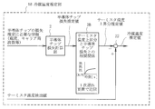
- FIG. 2 is a block diagram showing a refrigerant temperature estimation unit 1A, which is a main part of the first embodiment of the semiconductor chip temperature estimation device 6.
- the refrigerant temperature estimation unit 1A includes a semiconductor chip loss calculation unit 2, a correlation storage unit 3A that stores the correlation between the thermistor temperature rise and the semiconductor chip loss, and the output of the correlation storage unit 3A.
- Addition / subtraction means 22 for adding / subtracting the thermistor temperature detection value with the sign shown in the figure.
- the refrigerant temperature estimation unit 1A is configured by hardware such as a CPU and a memory and software for executing a predetermined calculation.
- the semiconductor chip loss calculation unit 2 constitutes the first estimation unit in the claims
- the correlation storage unit 3A constitutes the storage unit and the second estimation unit in the claims
- the addition / subtraction unit 22 corresponds to the first estimation unit in the claims.
- 3 estimation means are configured.
- the semiconductor chip loss calculation unit 2 has a function of estimating and calculating the loss of one semiconductor chip, such as a current detection value by the current detector 19 and a carrier frequency (switching frequency) from the PWM circuit 8. Information necessary for loss estimation is entered. In addition to the current detection value and the carrier frequency described above, the characteristics of the switching element and the free wheel diode are input to the semiconductor chip loss calculation unit 2, and the conduction calculated by using each of the switching element and the free wheel diode is estimated. It is desirable to output the total value of the loss and the switching loss as the semiconductor chip loss estimated value.
- the correlation between the thermistor temperature rise and the semiconductor chip loss is stored in advance.
- the correlation stored in the correlation storage unit 3 ⁇ / b> A in this way, the thermistor temperature rise is estimated from the semiconductor chip loss estimated value 2, and the thermistor temperature rise estimated value is input to the addition / subtraction means 22.
- a temperature detection value by the thermistor 17 built in the semiconductor module 18 is also input to the addition / subtraction means 22.
- the semiconductor chip temperature estimated value can be obtained by adding the refrigerant temperature estimated value and the output (semiconductor chip temperature rising estimated value) of the semiconductor chip temperature rising estimation unit 4 in FIG. it can.
- the current limit command circuit 7 outputs a current limit command when the estimated semiconductor chip temperature exceeds the set value, and changes the on-duty of the semiconductor switching element or turns off the semiconductor switching element via the PWM circuit 8.
- a protective operation is performed by a current limiting operation such as The configuration of the semiconductor chip temperature rise estimation unit 4 will be described with reference to a fifth embodiment to be described later, but may basically be the same as the temperature rise estimation means 210a shown in FIG.
- the temperature detection value is input to the refrigerant temperature estimating unit 1A together with information necessary for estimating the loss of the semiconductor chip.
- the refrigerant temperature can be estimated without being installed separately. Thereby, overheat protection can be performed without increasing the number of parts, and the cost and size of the power converter can be reduced.
- the thermistor temperature detection value (temperature detection value of the cooling body or refrigerant) is used as the reference temperature of the semiconductor chip temperature estimation value, and this reference temperature is added / subtracted by the adding / subtracting means 210b.
- the semiconductor chip temperature estimated value is calculated by adding to the estimated increase value.
- the thermistor is affected by the heat generation of the semiconductor chip, and thus correctly estimates the temperature of the cooling body or the refrigerant. I can't. Therefore, when the temperature of the semiconductor chip is estimated using the thermistor temperature detection value as it is as the reference temperature as shown in FIG. 8, the estimation error of the semiconductor chip becomes large, and overheating protection may not be performed safely and reliably. Arise.
- the thermistor temperature rise is estimated using a correlation that takes into account the influence of the heat generation of the semiconductor chip on the thermistor, so that the estimated temperature rise is the thermistor temperature detection value.
- the refrigerant temperature can be accurately estimated, and as a result, the semiconductor chip temperature can be estimated with high accuracy.
- FIG. 3 is a block diagram of the refrigerant temperature estimation unit 1B, which is the main part of the second embodiment of the semiconductor chip temperature estimation device 6.
- the correlation between the thermistor temperature rise stored in the correlation storage unit 3B and the semiconductor chip loss is approximated by a first-order lag element as specifically expressed by Formula 1. .
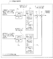
- FIG. 4 is a block diagram showing a refrigerant temperature estimation unit 1 ⁇ / b> C that is a main part of the third embodiment of the semiconductor chip temperature estimation device 6.
- the losses of a plurality of semiconductor chips that affect the temperature rise of the thermistor are estimated, and the estimated values of the thermistor temperature rise are obtained using the correlation between the thermistor temperature rise and the semiconductor chip loss.
- the refrigerant temperature is estimated by adding the estimated values of the thermistor temperature rises and subtracting them from the thermistor temperature detection value.
- the semiconductor chip loss calculation units 2C 1 and 2C 2 estimate the losses of two semiconductor chips, such as the semiconductor chips 11 and 12 in FIG. 1, for example, and the calculation units 2C 1 and 2C, respectively. 2 features 2, is the same as that of the semiconductor chip loss calculation unit 2 in FIG.
- the correlation storage units 3C 1 and 3C 2 approximate the correlation between the thermistor temperature rise and the semiconductor chip loss by, for example, a first order lag element.
- the correlation stored in the correlation storage units 3C 1 and 3C 2 is not necessarily the same.
- the thermistor temperature rise estimated values estimated using the respective correlations in the same manner as in the second embodiment are added by the addition / subtraction means 23, and the addition value is subtracted from the thermistor temperature detection value in the subsequent addition / subtraction means 22.
- the estimated refrigerant temperature value is obtained.
- the semiconductor chip in the vicinity of the thermistor 17 but also the heat generated by the semiconductor chip disposed far from the thermistor 17 affects the temperature rise of the thermistor 17.
- By estimating the thermistor temperature rise by using the correlation between the individual loss and the thermistor temperature rise it is possible to estimate the refrigerant temperature more accurately and thus the semiconductor chip temperature with high accuracy. .
- FIG. 5 is a block diagram showing a refrigerant temperature estimation unit 1D which is a main part of the fourth embodiment of the semiconductor chip temperature estimation device 6.
- the correlation between the thermistor temperature rise stored in the correlation storage unit 3D and the semiconductor chip loss is approximated by the sum of a plurality of first-order lag elements as shown in Equation 2, for example. .
- This Formula 2 is a total of n first-order lag elements shown in Formula 1.
- an actual correlation can be obtained by combining a plurality of first-order lag elements.
- the refrigerant temperature can be estimated with higher accuracy.
- FIG. 6 is a block diagram showing a fifth embodiment of the semiconductor chip temperature estimating device 6.
- the fifth embodiment includes the refrigerant temperature estimation section 1A shown in the first embodiment of FIG. 2, the semiconductor chip temperature rise estimation section 4 and the addition / subtraction means 5 in FIG. 1, and the semiconductor of FIG. This corresponds to a specific implementation of the overall configuration of the chip temperature estimation device 6.
- the semiconductor chip temperature rise estimation unit 4 has substantially the same configuration as the temperature rise estimation unit 210a in FIG. 8, and includes a semiconductor chip loss calculation unit 41 and a semiconductor chip temperature rise calculation unit. Similar to the semiconductor chip loss calculation unit 2 of the refrigerant temperature estimation unit 1A, the semiconductor chip loss calculation unit 41 has a function of estimating and calculating the loss of one semiconductor chip, and current detection by the current detector 19 in FIG. The loss of the semiconductor chip is estimated based on information necessary for estimating the loss of the semiconductor chip, such as the value and the carrier frequency from the PWM circuit 8.
- the semiconductor chip temperature rise calculation unit 42 estimates the temperature rise due to heat generation according to the loss from the semiconductor chip loss estimated value, and outputs it as the semiconductor chip temperature rise estimated value.
- the semiconductor chip temperature rise estimation unit 4 constitutes the fourth estimation means in the claims
- the semiconductor chip loss calculation unit 41 constitutes the fifth estimation means
- the semiconductor chip temperature rise calculation unit 42 6th estimation means is comprised.
- the semiconductor chip temperature estimation is performed.
- the value can be determined.
- the semiconductor chip temperature estimated value is input to the current limit command circuit 7 of FIG. 1 and compared with a set value, so that a current limit operation or the like may be performed as necessary.
- the refrigerant temperature estimation unit 1A can estimate the refrigerant temperature in real time and with high accuracy without being affected by the heat generation of the semiconductor chip. By adding the estimated value of the refrigerant temperature and the estimated value of the semiconductor chip temperature rise, the semiconductor chip temperature can be estimated with high accuracy, which can be used for overheating protection of the semiconductor chip and the power converter.
- the refrigerant temperature estimation units 1B to 1D in FIGS. 3 to 5 may be used.
- the semiconductor chip temperature estimation device can be used for temperature estimation of a semiconductor chip having various semiconductor switching elements such as IGBT, FET, thyristor and the like.
- the overheat protection device can be used for overheat protection of various power converters such as inverters, converters, and choppers in which the semiconductor chip is mounted as a semiconductor module.
- cooling element temperature estimation unit 1A, 1B, 1C, 1D refrigerant temperature estimation unit 2,2C 1, 2C 2: semiconductor chip loss calculation unit 3A, 3B, 3C 1, 3C 2, 3D: correlation storing section 4: Semiconductor chip temperature rise estimation unit 5, 22, 23: addition / subtraction means 6: semiconductor chip temperature estimation device 7: current limit command circuit 8: PWM circuit 9: gate drive circuit 10: smoothing capacitors 11 to 16: semiconductor chip 17: thermistor 18: Semiconductor module 19: Current detector 20: Motor 21: Heat sink 41: Semiconductor chip loss calculator 42: Semiconductor chip temperature rise calculator
Landscapes
- Physics & Mathematics (AREA)
- General Physics & Mathematics (AREA)
- Engineering & Computer Science (AREA)
- Power Engineering (AREA)
- Nonlinear Science (AREA)
- Power Conversion In General (AREA)
- Inverter Devices (AREA)
- Semiconductor Integrated Circuits (AREA)
- Cooling Or The Like Of Semiconductors Or Solid State Devices (AREA)
Abstract
半導体モジュールにサーミスタと共に内蔵された半導体チップの温度を推定する半導体チップ温度推定装置において、半導体チップ内の半導体スイッチング素子の電流及びスイッチング周波数等を用いて、演算により半導体チップの損失を推定する損失計算部2と、サーミスタによる温度検出値と半導体モジュールを冷却する冷媒等の冷却要素の温度との差である温度上昇分と、半導体チップの損失との相関関係が予め記憶された記憶部3Aと、損失計算部2から出力される半導体チップ損失推定値と前記相関関係とを用いて、演算によりサーミスタの温度上昇分を推定する手段と、サーミスタ温度上昇分推定値をその温度検出値から差し引いて冷却要素温度を推定する加減算手段22と、を備え、冷却要素温度推定値を基礎温度として半導体チップの温度を推定する。これにより、冷却要素温度を検出するサーミスタを不要にし、電力変換器の小型化、低コスト化を図る。
Description
本発明は、例えば、半導体モジュールを構成する半導体チップの温度推定装置、及び、この温度推定装置を用いて電力変換器を過熱事故から保護するための過熱保護装置に関するものである。
半導体モジュールが搭載された電力変換器において、半導体モジュールを構成する半導体チップの温度を推定し、推定した温度が許容温度を超えて破壊に至るまでに半導体チップに流れる電流を制限して半導体チップや電力変換器の過熱保護を実現する方法がある。このような半導体チップの温度を推定する従来技術が、特許文献1や特許文献2に開示されている。
図7は、特許文献1に記載された従来技術を示すブロック図である。
図7において、101は三相交流電源(図示せず)に接続された整流回路、102は平滑コンデンサ、103は、インバータ104及びサーミスタ105が設置されたヒートシンク、106はインバータ104により駆動されるモータである。また、200はインバータ104の半導体スイッチング素子を制御する制御装置、201,202は第1,第2の設定温度、203は電流検出器、204,205はコンパレータ、206は電流遮断機能、207は電流制限機能、208はPWM制御部、209は温度検出部、210はTj(ジャンクション温度)推定部である。
図7において、101は三相交流電源(図示せず)に接続された整流回路、102は平滑コンデンサ、103は、インバータ104及びサーミスタ105が設置されたヒートシンク、106はインバータ104により駆動されるモータである。また、200はインバータ104の半導体スイッチング素子を制御する制御装置、201,202は第1,第2の設定温度、203は電流検出器、204,205はコンパレータ、206は電流遮断機能、207は電流制限機能、208はPWM制御部、209は温度検出部、210はTj(ジャンクション温度)推定部である。
この従来技術では、サーミスタ105及び温度検出部209により得たヒートシンク103の温度検出値、電流検出器203によるモータ106の電流検出値、及びPWM制御部208によるドライブ信号(キャリア周波数)がTj推定部210に入力される。Tj推定部210では、電流検出値とドライブ信号とに基づいて導通損失及びスイッチング損失に応じた温度上昇分を求め、この温度上昇分をヒートシンク103の温度検出値に加算して半導体スイッチング素子のジャンクション温度(半導体チップ温度)を推定している。
そして、推定した半導体チップ温度が第1の設定温度201を超えたら、電流制限機能207によりインバータ104の電流を制限し、半導体チップ温度が第1の設定温度201より高い第2の設定温度202を超えたら、電流遮断機能206によりインバータ104の電流を遮断して過熱保護を実現している。
そして、推定した半導体チップ温度が第1の設定温度201を超えたら、電流制限機能207によりインバータ104の電流を制限し、半導体チップ温度が第1の設定温度201より高い第2の設定温度202を超えたら、電流遮断機能206によりインバータ104の電流を遮断して過熱保護を実現している。
なお、特許文献2には、同期電動機がストール状態になった時に、半導体チップ温度推定値が許容値を超えないようにインバータの出力電流を制限するようにした電力変換器の制御装置が開示されている。
特許文献1,2に記載された従来技術では、サーミスタ等の温度センサによる温度検出値を、半導体チップを冷却するための冷却体または冷媒の温度検出値とみなし、この温度検出値に、半導体チップの損失に起因した温度上昇分を加算することによって半導体チップの温度を推定している。
例えば図8は、図7のTj推定部210における半導体チップの温度推定機能を示す概念図であり、210aは温度上昇推定手段、210bは加減算手段、210cは半導体チップ損失計算部、210dは半導体チップ温度上昇分計算部である。図示するように、Tj推定部210では、半導体チップの損失に起因した温度上昇分推定値とサーミスタ105による温度検出値との加算値を、半導体チップの温度推定値として出力する。
例えば図8は、図7のTj推定部210における半導体チップの温度推定機能を示す概念図であり、210aは温度上昇推定手段、210bは加減算手段、210cは半導体チップ損失計算部、210dは半導体チップ温度上昇分計算部である。図示するように、Tj推定部210では、半導体チップの損失に起因した温度上昇分推定値とサーミスタ105による温度検出値との加算値を、半導体チップの温度推定値として出力する。
前述したように、特許文献1,2では、半導体チップ温度を推定する基準温度となる冷却体温度や冷媒温度を検出することが前提であり、そのためにサーミスタ等の温度センサを冷却体に設置する必要がある。
このため、上記温度センサによって部品点数が増加し、電力変換器のコスト増加や大型化を招くという問題があった。
このため、上記温度センサによって部品点数が増加し、電力変換器のコスト増加や大型化を招くという問題があった。
上記問題に対して、複数の半導体チップからなる半導体モジュールにサーミスタを内蔵することにより、冷却体等に別途、サーミスタを設置せずに、半導体モジュール内蔵のサーミスタによって冷却体等の温度を推定する方法がある。しかし、この方法によると、サーミスタ近傍の半導体チップの発熱の影響により、サーミスタが冷却体等の温度を正確に推定できない場合がある。
また、半導体モジュールに内蔵したサーミスタによって半導体チップの温度を推定し、過熱保護を行う方法もある。しかしながら、この方法では、サーミスタから遠い位置にある半導体チップが発熱してサーミスタ近傍の半導体チップが殆ど発熱しない状態において、サーミスタは遠い位置にある半導体チップの発熱の影響を殆ど受けないため、過熱保護を有効に行なえないという問題があった。
そこで、本発明の解決課題は、サーミスタ等の温度センサ近傍の半導体チップが発熱した場合でも、半導体チップ温度を推定する基礎温度となる冷却体や冷媒(以下、これらを総称して「冷却要素」ともいう)の温度を正確に推定することにより、冷却要素の温度を検出する温度センサを不要にして電力変換器のコストの低減及び小型化を図った半導体チップ温度推定装置を提供することにある。また、本発明の別の解決課題は、半導体チップ温度推定値に基づく電流制限動作により、半導体チップや電力変換器を過熱事故から保護するようにした過熱保護装置を提供することにある。
上記課題を解決するため、本発明の半導体チップ温度推定装置は、半導体モジュールにサーミスタ等の温度センサと共に内蔵された半導体チップの温度を推定する半導体チップ温度推定装置に関するものである。
まず、請求項1に係る半導体チップ温度推定装置は、半導体チップ内の半導体スイッチング素子の電流及びスイッチング周波数を少なくとも用いて、演算により半導体チップの損失を推定する第1の推定手段と、
温度センサによる温度検出値と半導体モジュールを冷却するための冷媒や冷却体等の冷却要素の温度との差である温度上昇分と、半導体チップの損失との相関関係が予め記憶された記憶手段と、
第1の推定手段から出力される半導体チップの損失推定値と前記相関関係とを用いて、温度センサの温度上昇分を推定する第2の推定手段と、
第2の推定手段から出力される温度センサの温度上昇分推定値を、温度センサによる温度検出値から差し引いて冷却要素温度を推定する第3の推定手段と、を備え、
第3の推定手段から出力される冷却要素温度の推定値を基礎温度として、半導体チップの温度を推定するものである。
まず、請求項1に係る半導体チップ温度推定装置は、半導体チップ内の半導体スイッチング素子の電流及びスイッチング周波数を少なくとも用いて、演算により半導体チップの損失を推定する第1の推定手段と、
温度センサによる温度検出値と半導体モジュールを冷却するための冷媒や冷却体等の冷却要素の温度との差である温度上昇分と、半導体チップの損失との相関関係が予め記憶された記憶手段と、
第1の推定手段から出力される半導体チップの損失推定値と前記相関関係とを用いて、温度センサの温度上昇分を推定する第2の推定手段と、
第2の推定手段から出力される温度センサの温度上昇分推定値を、温度センサによる温度検出値から差し引いて冷却要素温度を推定する第3の推定手段と、を備え、
第3の推定手段から出力される冷却要素温度の推定値を基礎温度として、半導体チップの温度を推定するものである。
請求項2に係る半導体チップ温度推定装置は、請求項1における前記相関関係が、温度センサの温度上昇分と半導体チップの損失との関係を1次遅れ要素により近似したものであることを特徴とする。
請求項3に係る半導体チップ温度推定装置は、請求項1における第1の推定手段、記憶手段、及び第2の推定手段を、複数の半導体チップに対応させてそれぞれ設け、第3の推定手段は、複数の第2の推定手段から出力される温度上昇分推定値の合計値を、温度センサによる温度検出値から差し引いて冷却要素温度を推定するものである。
請求項4に係る半導体チップ温度推定装置は、請求項1における前記相関関係が、温度センサの温度上昇分と半導体チップの損失との関係を複数の1次遅れ要素の和により近似したものであることを特徴とする。
請求項5に係る半導体チップ温度推定装置は、請求項1~4の何れか1項に記載した半導体チップ温度推定装置において、半導体チップの温度上昇分を演算により推定する第4の推定手段を設け、この第4の推定手段から出力される半導体チップ温度上昇分推定値と第3の推定手段から出力される冷却要素温度推定値とを加算して半導体チップの温度推定値を求めるものである。
請求項6に係る半導体チップ温度推定装置は、請求項5における第4の推定手段が、半導体チップ内の半導体スイッチング素子の電流及びスイッチング周波数を少なくとも用いて、演算により半導体チップの損失を推定する第5の推定手段と、この第5の推定手段から出力される半導体チップの損失推定値を用いて、演算により半導体チップの温度上昇分を推定する第6の推定手段と、を備えたものである。
請求項7に係る半導体チップ温度推定装置は、請求項1~4の何れか1項に記載した半導体チップ温度推定装置において、前記冷却要素が、前記半導体モジュールを冷却する冷媒であることを特徴とする。
請求項8に係る過熱保護装置は、請求項1~4の何れか1項に記載した半導体チップ温度推定値から出力される半導体チップの温度推定値が設定値を超えた時に、半導体チップ内の半導体スイッチング素子の動作を制御して半導体スイッチング素子に流れる電流を制限する手段を備えたものである。
本発明によれば、サーミスタ等の温度センサを冷媒や冷却体等の冷却要素に別途、設置することなく冷却要素温度を推定することができる。このため、部品点数を削減して電力変換器の小型化、低コスト化を達成することができる。
また、温度センサが近傍の半導体チップの発熱の影響を受けたとしても、所定の相関関係に基づく温度上昇分を温度センサによる温度検出値から差し引くことで、冷却要素温度を高精度に推定することができる。
上記のように、本発明では冷却要素温度推定値の信頼性が高いため、この冷却要素温度推定値を基礎温度とした半導体チップ温度推定値の信頼性も高くなり、半導体チップや電力変換器の過熱保護を安全かつ確実に行うことができる。
また、温度センサが近傍の半導体チップの発熱の影響を受けたとしても、所定の相関関係に基づく温度上昇分を温度センサによる温度検出値から差し引くことで、冷却要素温度を高精度に推定することができる。
上記のように、本発明では冷却要素温度推定値の信頼性が高いため、この冷却要素温度推定値を基礎温度とした半導体チップ温度推定値の信頼性も高くなり、半導体チップや電力変換器の過熱保護を安全かつ確実に行うことができる。
以下、図に沿って本発明の実施形態を説明する。
まず、図1は、本発明の実施形態が適用される電力変換装置のブロック図である。この電力変換装置は、三相インバータからなる電力変換器によりモータを駆動する主回路と、前記インバータの制御装置とによって構成されている。
まず、図1は、本発明の実施形態が適用される電力変換装置のブロック図である。この電力変換装置は、三相インバータからなる電力変換器によりモータを駆動する主回路と、前記インバータの制御装置とによって構成されている。
図1の主回路において、10は直流電圧が印加される平滑コンデンサ、11~16はIGBT等の半導体スイッチング素子及び還流ダイオードからなる半導体チップ、17は温度センサとしてのサーミスタ、18は半導体モジュール、19は電流検出器、20はインバータの負荷であるモータ、21は半導体チップ11~16を冷却するヒートシンクである。
なお、半導体スイッチング素子の種類や個数、電力変換器の種類や相数は特に限定されるものではない。
なお、半導体スイッチング素子の種類や個数、電力変換器の種類や相数は特に限定されるものではない。
一方、制御装置は、サーミスタ17からの温度検出値と、電流検出器19によるモータ20の電流検出値と、後述するPWM回路8からのキャリア周波数とが入力される本実施形態の半導体チップ温度推定装置6を有する。半導体チップ温度推定装置6は、冷却要素温度推定部1と、半導体チップ温度上昇分推定部4と、両者の出力を加算する加減算手段5とを備えており、この半導体チップ温度推定装置6から出力される半導体チップ温度推定値は、電流制限指令回路7に入力されている。
電流制限指令回路7は、半導体チップ温度推定値が設定値を超えた場合に、半導体スイッチング素子を流れる電流(インバータの出力電流)を制限するための電流制限指令を生成する。ここで、電流制限指令には、電流をゼロに制限する(半導体スイッチング素子をオフさせる)指令も含む。
上記電流制限指令は、PWM回路8に入力される。このPWM回路8は、図示されていない制御回路からの電圧指令に基づきPWM信号を生成して後続のゲート駆動回路9に出力する。ゲート駆動回路9は、ゲート信号を生成して半導体チップ11~16内の半導体スイッチング素子をオンオフさせることにより、半導体チップ11~16からなるインバータの直流/交流変換動作によってモータ20に三相交流電力を供給する。
次に、この実施形態に係る半導体チップ温度推定装置6の実施例を、図2~図6に従って説明する。
なお、以下の実施例では、図1の半導体モジュール18を冷却する冷却要素がヒートシンク21を強制冷却する水などの冷媒であるものとし、図1における冷却要素温度推定部1を冷媒温度推定部1B~1Dとして具体化してある。ここで、冷却要素としては、冷媒以外に冷却フィン等の冷却体を用いても良く、その場合には冷却要素温度として冷却体温度を推定することになる。
なお、以下の実施例では、図1の半導体モジュール18を冷却する冷却要素がヒートシンク21を強制冷却する水などの冷媒であるものとし、図1における冷却要素温度推定部1を冷媒温度推定部1B~1Dとして具体化してある。ここで、冷却要素としては、冷媒以外に冷却フィン等の冷却体を用いても良く、その場合には冷却要素温度として冷却体温度を推定することになる。
まず、図2は、半導体チップ温度推定装置6の第1実施例の主要部である冷媒温度推定部1Aを示すブロック図である。
図2において、冷媒温度推定部1Aは、半導体チップ損失計算部2と、サーミスタ温度上昇分と半導体チップ損失との相関関係が記憶された相関関係記憶部3Aと、相関関係記憶部3Aの出力とサーミスタ温度検出値とを図示の符号で加減算する加減算手段22と、を備えている。この冷媒温度推定部1Aは、CPU及びメモリ等のハードウェアと所定の演算を実行するソフトウェアとによって構成されており、この点は、後述の冷媒温度推定部1B~1D及び半導体チップ温度上昇分推定部4についても同様である。
なお、半導体チップ損失計算部2は請求項における第1の推定手段を構成し、相関関係記憶部3Aは請求項における記憶手段及び第2の推定手段を構成し、加減算手段22は請求項における第3の推定手段を構成している。
図2において、冷媒温度推定部1Aは、半導体チップ損失計算部2と、サーミスタ温度上昇分と半導体チップ損失との相関関係が記憶された相関関係記憶部3Aと、相関関係記憶部3Aの出力とサーミスタ温度検出値とを図示の符号で加減算する加減算手段22と、を備えている。この冷媒温度推定部1Aは、CPU及びメモリ等のハードウェアと所定の演算を実行するソフトウェアとによって構成されており、この点は、後述の冷媒温度推定部1B~1D及び半導体チップ温度上昇分推定部4についても同様である。
なお、半導体チップ損失計算部2は請求項における第1の推定手段を構成し、相関関係記憶部3Aは請求項における記憶手段及び第2の推定手段を構成し、加減算手段22は請求項における第3の推定手段を構成している。
半導体チップ損失計算部2は、1個の半導体チップの損失を推定演算する機能を有し、電流検出器19による電流検出値やPWM回路8からのキャリア周波数(スイッチング周波数)等の、半導体チップの損失推定に必要な情報が入力されている。なお、半導体チップ損失計算部2には、上述した電流検出値やキャリア周波数の他にスイッチング素子や還流ダイオードの特性等を入力し、これらを用いてスイッチング素子や還流ダイオードの各々について推定演算した導通損失とスイッチング損失との合計値を、半導体チップ損失推定値として出力することが望ましい。
図2の相関関係記憶部3Aには、サーミスタ温度上昇分と半導体チップ損失との相関関係が予め記憶されている。
ここで、サーミスタ温度上昇分(=サーミスタ温度検出値-冷媒温度)とは、冷媒温度を基準温度とした、半導体チップの発熱によるサーミスタ17の温度検出値であり、予め測定可能である。なお、冷媒温度は一定とする。
また、半導体チップ損失に起因する発熱とサーミスタ温度検出値との関係も予め測定可能であるから、半導体チップ損失とサーミスタ温度上昇分との相関関係を予め求めて相関関係記憶部3Aに記憶しておくことができる。
このようにして相関関係記憶部3Aに記憶された相関関係を用いることにより、半導体チップ損失推定値2からサーミスタ温度上昇分を推定し、そのサーミスタ温度上昇分推定値を加減算手段22に入力する。
ここで、サーミスタ温度上昇分(=サーミスタ温度検出値-冷媒温度)とは、冷媒温度を基準温度とした、半導体チップの発熱によるサーミスタ17の温度検出値であり、予め測定可能である。なお、冷媒温度は一定とする。
また、半導体チップ損失に起因する発熱とサーミスタ温度検出値との関係も予め測定可能であるから、半導体チップ損失とサーミスタ温度上昇分との相関関係を予め求めて相関関係記憶部3Aに記憶しておくことができる。
このようにして相関関係記憶部3Aに記憶された相関関係を用いることにより、半導体チップ損失推定値2からサーミスタ温度上昇分を推定し、そのサーミスタ温度上昇分推定値を加減算手段22に入力する。
一方、半導体モジュール18に内蔵されたサーミスタ17による温度検出値も、加減算手段22に入力されている。加減算手段22では、このサーミスタ温度検出値(前述のごとく、サーミスタ温度検出値=サーミスタ温度上昇分+冷媒温度)から前記サーミスタ温度上昇分推定値を差し引くことにより、冷媒温度を推定することができる。
なお、この冷媒温度推定値と、図1における半導体チップ温度上昇分推定部4の出力(半導体チップ温度上昇分推定値)とを加減算手段5により加算すれば、半導体チップ温度推定値を求めることができる。電流制限指令回路7は、この半導体チップ温度推定値が設定値を超えたときに電流制限指令を出力し、PWM回路8を介して半導体スイッチング素子のオンデューティを変化させたり半導体スイッチング素子をオフさせる等の電流制限動作によって保護動作を行う。
半導体チップ温度上昇分推定部4の構成は、後述する第5実施例により説明するが、基本的には、図8に示した温度上昇推定手段210aと同一で良い。
なお、この冷媒温度推定値と、図1における半導体チップ温度上昇分推定部4の出力(半導体チップ温度上昇分推定値)とを加減算手段5により加算すれば、半導体チップ温度推定値を求めることができる。電流制限指令回路7は、この半導体チップ温度推定値が設定値を超えたときに電流制限指令を出力し、PWM回路8を介して半導体スイッチング素子のオンデューティを変化させたり半導体スイッチング素子をオフさせる等の電流制限動作によって保護動作を行う。
半導体チップ温度上昇分推定部4の構成は、後述する第5実施例により説明するが、基本的には、図8に示した温度上昇推定手段210aと同一で良い。
上記のように、第1実施例によれば、サーミスタ内蔵の半導体モジュール18を用いてその温度検出値を半導体チップの損失推定に必要な情報と共に冷媒温度推定部1Aに入力することにより、サーミスタを別途、設置することなく冷媒温度を推定することができる。これにより、部品点数を増加させずに過熱保護を行うことができ、電力変換器の低コスト化、小型化が可能になる。
ここで、図8に示した従来技術では、サーミスタ温度検出値(冷却体または冷媒の温度検出値)を半導体チップ温度推定値の基準温度として用い、この基準温度を加減算手段210bにて半導体チップ温度上昇分推定値に加算して半導体チップ温度推定値を演算している。
この場合、冷却体または冷媒の温度を検出するためのサーミスタの近傍に配置された半導体チップが発熱すると、サーミスタは当該半導体チップの発熱の影響を受けるため、冷却体または冷媒の温度を正しく推定することができない。従って、図8のようにサーミスタ温度検出値をそのまま基準温度に用いて半導体チップの温度を推定する場合には、半導体チップ温度の推定誤差が大きくなり、過熱保護を安全、確実に行えない場合が生じる。
この場合、冷却体または冷媒の温度を検出するためのサーミスタの近傍に配置された半導体チップが発熱すると、サーミスタは当該半導体チップの発熱の影響を受けるため、冷却体または冷媒の温度を正しく推定することができない。従って、図8のようにサーミスタ温度検出値をそのまま基準温度に用いて半導体チップの温度を推定する場合には、半導体チップ温度の推定誤差が大きくなり、過熱保護を安全、確実に行えない場合が生じる。
これに対し、本実施例によれば、サーミスタに及ぼす半導体チップの発熱の影響を考慮した相関関係を用いてサーミスタ温度上昇分を推定しているため、その温度上昇分推定値をサーミスタ温度検出値から差し引くことにより冷媒温度を正確に推定し、結果として半導体チップ温度を高精度に推定することができる。
次に、図3は、半導体チップ温度推定装置6の第2実施例の主要部である冷媒温度推定部1Bのブロック図である。この第2実施例では、相関関係記憶部3Bに記憶されるサーミスタ温度上昇分と半導体チップ損失との相関関係を、具体的に数式1で表されるような1次遅れ要素により近似している。

上記のような方法とは別に、サーミスタ温度上昇分と半導体チップ損失との相関関係をテーブルデータとして表す方法も挙げられるが、この方法では、サーミスタ温度上昇分における熱時定数Tcの影響を無視せざるを得ず、例えば負荷であるモータ20の低速回転時や加減速運転時において電流が過渡的に変化する場合のサーミスタ温度上昇分を推定することができない。
このような観点から、前記相関関係を数式1のような1次遅れ要素によって近似することにより、冷媒温度ひいては半導体チップ温度を正確かつリアルタイムに推定することができる。
なお、数式1における定常熱抵抗Rは、R≒半導体チップ温度上昇分/半導体チップ損失という関係にあるから、半導体チップ損失推定値から数式1の相関関係Rthを介してサーミスタ温度上昇分を推定することは容易である。
このような観点から、前記相関関係を数式1のような1次遅れ要素によって近似することにより、冷媒温度ひいては半導体チップ温度を正確かつリアルタイムに推定することができる。
なお、数式1における定常熱抵抗Rは、R≒半導体チップ温度上昇分/半導体チップ損失という関係にあるから、半導体チップ損失推定値から数式1の相関関係Rthを介してサーミスタ温度上昇分を推定することは容易である。
図4は、半導体チップ温度推定装置6の第3実施例の主要部である冷媒温度推定部1Cを示すブロック図である。
この第3実施例では、サーミスタの温度上昇に影響を及ぼす複数個の半導体チップの損失を推定し、サーミスタ温度上昇分と半導体チップ損失との相関関係を用いてサーミスタ温度上昇分推定値をそれぞれ求め、これら複数のサーミスタ温度上昇分推定値を加算してサーミスタ温度検出値から差し引くことにより、冷媒温度を推定する。
この第3実施例では、サーミスタの温度上昇に影響を及ぼす複数個の半導体チップの損失を推定し、サーミスタ温度上昇分と半導体チップ損失との相関関係を用いてサーミスタ温度上昇分推定値をそれぞれ求め、これら複数のサーミスタ温度上昇分推定値を加算してサーミスタ温度検出値から差し引くことにより、冷媒温度を推定する。
図4において、半導体チップ損失計算部2C1,2C2は、例えば図1における半導体チップ11,12のように2個の半導体チップの損失をそれぞれ推定するものであり、各計算部2C1,2C2の機能は図2,図3における半導体チップ損失計算部2と同様である。
また、相関関係記憶部3C1,3C2は、第2実施例のように、サーミスタ温度上昇分と半導体チップ損失との相関関係を例えば1次遅れ要素により近似している。但し、一般的に各半導体チップとサーミスタ17との位置関係によって上記相関関係が異なるので、相関関係記憶部3C1,3C2に記憶される相関関係は必ずしも同一ではない。
また、相関関係記憶部3C1,3C2は、第2実施例のように、サーミスタ温度上昇分と半導体チップ損失との相関関係を例えば1次遅れ要素により近似している。但し、一般的に各半導体チップとサーミスタ17との位置関係によって上記相関関係が異なるので、相関関係記憶部3C1,3C2に記憶される相関関係は必ずしも同一ではない。
第2実施例と同様にしてそれぞれの相関関係を用いて推定したサーミスタ温度上昇分推定値は、加減算手段23により加算され、その加算値が、後続の加減算手段22においてサーミスタ温度検出値から差し引かれることにより、冷媒温度推定値が求められる。
この第2実施例によれば、サーミスタ17の近傍の半導体チップだけでなく、サーミスタ17の遠くに配置された半導体チップによる発熱がサーミスタの温度上昇に影響を及ぼす場合においても、これら複数の半導体チップについて個々の損失とサーミスタ温度上昇分との相関関係を用いてサーミスタ温度上昇分を推定することにより、冷媒温度を一層正確に推定し、ひいては半導体チップ温度を高精度に推定することが可能となる。
なお、図4ではサーミスタ温度上昇に影響を及ぼす半導体チップが2個の場合を示しているが、3個以上の半導体チップについてそれぞれ損失を推定すると共に相関関係を設定し、前記同様にサーミスタ温度上昇分を推定しても良いことは言うまでもない。
この第2実施例によれば、サーミスタ17の近傍の半導体チップだけでなく、サーミスタ17の遠くに配置された半導体チップによる発熱がサーミスタの温度上昇に影響を及ぼす場合においても、これら複数の半導体チップについて個々の損失とサーミスタ温度上昇分との相関関係を用いてサーミスタ温度上昇分を推定することにより、冷媒温度を一層正確に推定し、ひいては半導体チップ温度を高精度に推定することが可能となる。
なお、図4ではサーミスタ温度上昇に影響を及ぼす半導体チップが2個の場合を示しているが、3個以上の半導体チップについてそれぞれ損失を推定すると共に相関関係を設定し、前記同様にサーミスタ温度上昇分を推定しても良いことは言うまでもない。
次に、図5は、半導体チップ温度推定装置6の第4実施例の主要部である冷媒温度推定部1Dを示すブロック図である。
この第4実施例では、相関関係記憶部3Dに記憶されるサーミスタ温度上昇分と半導体チップ損失との相関関係を、例えば数式2に示すような複数の1次遅れ要素の和によって近似している。なお、この数式2は、数式1に示した1次遅れ要素をn個合計したものである。
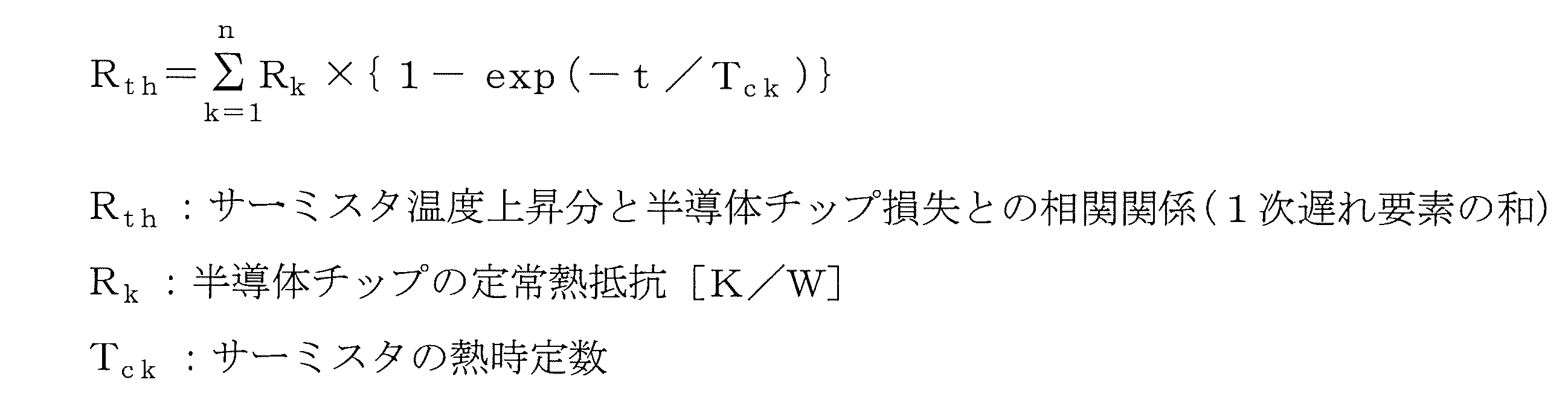
この第4実施例では、相関関係記憶部3Dに記憶されるサーミスタ温度上昇分と半導体チップ損失との相関関係を、例えば数式2に示すような複数の1次遅れ要素の和によって近似している。なお、この数式2は、数式1に示した1次遅れ要素をn個合計したものである。
この第4実施例によれば、第2実施例のように単一の1次遅れ要素では厳密には近似できない相関関係であっても、複数の1次遅れ要素を組み合わせることで実際の相関関係に近づけて模擬することができ、より高精度に冷媒温度を推定することが可能になる。
更に、図6は、半導体チップ温度推定装置6の第5実施例を示すブロック図である。
この第5実施例は、図2の第1実施例に示した冷媒温度推定部1Aと、図1における半導体チップ温度上昇分推定部4及び加減算手段5と、を備えており、図1の半導体チップ温度推定装置6の全体的な構成を具体化したものに相当する。
この第5実施例は、図2の第1実施例に示した冷媒温度推定部1Aと、図1における半導体チップ温度上昇分推定部4及び加減算手段5と、を備えており、図1の半導体チップ温度推定装置6の全体的な構成を具体化したものに相当する。
ここで、冷媒温度推定部1Aの構成、機能は第1実施例と同一である。
半導体チップ温度上昇分推定部4は、図8における温度上昇推定手段210aと実質的に同様の構成であり、半導体チップ損失計算部41と半導体チップ温度上昇分計算部42とを備えている。
半導体チップ損失計算部41は、冷媒温度推定部1Aの半導体チップ損失計算部2と同様に、1個の半導体チップの損失を推定演算する機能を有し、図1の電流検出器19による電流検出値やPWM回路8からのキャリア周波数等の、半導体チップの損失推定に必要な情報に基づいて半導体チップの損失を推定する。半導体チップ温度上昇分計算部42は、半導体チップ損失推定値から、その損失に応じた発熱による温度上昇分を推定し、半導体チップ温度上昇分推定値として出力する。
上記構成において、半導体チップ温度上昇分推定部4は請求項における第4の推定手段を構成し、半導体チップ損失計算部41は第5の推定手段を構成し、半導体チップ温度上昇分計算部42は第6の推定手段を構成している。
半導体チップ温度上昇分推定部4は、図8における温度上昇推定手段210aと実質的に同様の構成であり、半導体チップ損失計算部41と半導体チップ温度上昇分計算部42とを備えている。
半導体チップ損失計算部41は、冷媒温度推定部1Aの半導体チップ損失計算部2と同様に、1個の半導体チップの損失を推定演算する機能を有し、図1の電流検出器19による電流検出値やPWM回路8からのキャリア周波数等の、半導体チップの損失推定に必要な情報に基づいて半導体チップの損失を推定する。半導体チップ温度上昇分計算部42は、半導体チップ損失推定値から、その損失に応じた発熱による温度上昇分を推定し、半導体チップ温度上昇分推定値として出力する。
上記構成において、半導体チップ温度上昇分推定部4は請求項における第4の推定手段を構成し、半導体チップ損失計算部41は第5の推定手段を構成し、半導体チップ温度上昇分計算部42は第6の推定手段を構成している。
そして、冷媒温度推定部1Aから出力される冷媒温度推定値と半導体チップ温度上昇分推定部4から出力される半導体チップ温度上昇分推定値とを加減算手段5にて加算すれば、半導体チップ温度推定値を求めることができる。この半導体チップ温度推定値を図1の電流制限指令回路7に入力して設定値と比較することにより、必要に応じて電流制限動作等を行えば良い。
この第5実施例においても、サーミスタ17の近傍の半導体チップが発熱した場合に冷媒温度推定部1Aが上記半導体チップの発熱に影響されることなくリアルタイムかつ高精度に冷媒温度を推定することができ、この冷媒温度推定値と半導体チップ温度上昇分推定値とを加算することによって半導体チップ温度を高精度に推定し、半導体チップや電力変換器の過熱保護に役立てることができる。
なお、図6における冷媒温度推定部1Aの代わりに、図3~図5(第2~第4実施例)における冷媒温度推定部1B~1Dを用いても良い。
なお、図6における冷媒温度推定部1Aの代わりに、図3~図5(第2~第4実施例)における冷媒温度推定部1B~1Dを用いても良い。
本発明に係る半導体チップ温度推定装置は、IGBT,FET,サイリスタ等、各種の半導体スイッチング素子を有する半導体チップの温度推定に利用可能である。また、本発明に係る過熱保護装置は、上記半導体チップを半導体モジュールとして搭載したインバータ、コンバータ、チョッパ等の各種の電力変換器の過熱保護に利用することができる。
1:冷却要素温度推定部
1A,1B,1C,1D:冷媒温度推定部
2,2C1,2C2:半導体チップ損失計算部
3A,3B,3C1,3C2,3D:相関関係記憶部
4:半導体チップ温度上昇分推定部
5,22,23:加減算手段
6:半導体チップ温度推定装置
7:電流制限指令回路
8:PWM回路
9:ゲート駆動回路
10:平滑コンデンサ
11~16:半導体チップ
17:サーミスタ
18:半導体モジュール
19:電流検出器
20:モータ
21:ヒートシンク
41:半導体チップ損失計算部
42:半導体チップ温度上昇分計算部
1A,1B,1C,1D:冷媒温度推定部
2,2C1,2C2:半導体チップ損失計算部
3A,3B,3C1,3C2,3D:相関関係記憶部
4:半導体チップ温度上昇分推定部
5,22,23:加減算手段
6:半導体チップ温度推定装置
7:電流制限指令回路
8:PWM回路
9:ゲート駆動回路
10:平滑コンデンサ
11~16:半導体チップ
17:サーミスタ
18:半導体モジュール
19:電流検出器
20:モータ
21:ヒートシンク
41:半導体チップ損失計算部
42:半導体チップ温度上昇分計算部
Claims (8)
- 半導体モジュールに温度センサと共に内蔵された半導体チップの温度を推定する半導体チップ温度推定装置において、
前記半導体チップ内の半導体スイッチング素子の電流及びスイッチング周波数を少なくとも用いて、演算により前記半導体チップの損失を推定する第1の推定手段と、
前記温度センサによる温度検出値と前記半導体モジュールを冷却する冷却要素の温度である冷却要素温度との差である温度上昇分と、前記半導体チップの損失との相関関係が予め記憶された記憶手段と、
前記第1の推定手段から出力される前記半導体チップの損失推定値と前記相関関係とを用いて、演算により前記温度センサの温度上昇分を推定する第2の推定手段と、
前記第2の推定手段から出力される前記温度センサの温度上昇分推定値を、前記温度センサによる温度検出値から差し引いて前記冷却要素温度を推定する第3の推定手段と、
を備え、
前記第3の推定手段から出力される前記冷却要素温度の推定値を基礎温度として、前記半導体チップの温度を推定することを特徴とする半導体チップ温度推定装置。 - 請求項1に記載した半導体チップ温度推定装置において、
前記記憶手段に記憶される相関関係が、前記温度センサの温度上昇分と前記半導体チップの損失との関係を1次遅れ要素により近似したものであることを特徴とする半導体チップ温度推定装置。 - 請求項1に記載した半導体チップ温度推定装置において、
前記第1の推定手段、前記記憶手段、及び前記第2の推定手段を、複数の半導体チップに対応させてそれぞれ設け、前記第3の推定手段は、複数の前記第2の推定手段から出力される前記温度センサの温度上昇分推定値の合計値を、前記温度センサによる温度検出値から差し引いて前記冷却要素温度を推定することを特徴とする半導体チップ温度推定装置。 - 請求項1に記載した半導体チップ温度推定装置において、
前記記憶手段に記憶される相関関係が、前記温度センサの温度上昇分と前記半導体チップの損失との関係を複数の1次遅れ要素の和により近似したものであることを特徴とする半導体チップ温度推定装置。 - 請求項1~4の何れか1項に記載した半導体チップ温度推定装置において、
前記半導体チップの温度上昇分を演算により推定する第4の推定手段を設け、この第4の推定手段から出力される半導体チップ温度上昇分推定値と前記第3の推定手段から出力される冷却要素温度推定値とを加算して前記半導体チップの温度推定値を求めることを特徴とする半導体チップ温度推定装置。 - 請求項5に記載した半導体チップ温度推定装置において、
前記第4の推定手段は、
前記半導体チップ内の半導体スイッチング素子の電流及びスイッチング周波数を少なくとも用いて、演算により前記半導体チップの損失を推定する第5の推定手段と、
前記第5の推定手段から出力される前記半導体チップの損失推定値を用いて、演算により前記半導体チップの温度上昇分を推定する第6の推定手段と、
を備えたことを特徴とする半導体チップ温度推定装置。 - 請求項1~4の何れか1項に記載した半導体チップ温度推定装置において、
前記冷却要素が、前記半導体モジュールを冷却する冷媒であることを特徴とする半導体チップ温度推定装置。 - 請求項1~4の何れか1項に記載した半導体チップ温度推定値から出力される前記半導体チップの温度推定値が設定値を超えた時に、前記半導体スイッチング素子の動作を制御して前記半導体スイッチング素子に流れる電流を制限する手段を備えたことを特徴とする過熱保護装置。
Priority Applications (4)
| Application Number | Priority Date | Filing Date | Title |
|---|---|---|---|
| EP13861990.3A EP2933618A4 (en) | 2012-12-12 | 2013-11-11 | DEVICE FOR TEMPERATURE ESTIMATION OF A SEMICONDUCTOR CHIP AND OVERHEAT PROTECTION DEVICE |
| JP2014551932A JP5880734B2 (ja) | 2012-12-12 | 2013-11-11 | 半導体チップ温度推定装置及び過熱保護装置 |
| CN201380052097.4A CN104736981B (zh) | 2012-12-12 | 2013-11-11 | 半导体芯片温度推定装置及过热保护装置 |
| US14/680,056 US10156482B2 (en) | 2012-12-12 | 2015-04-06 | Semiconductor chip temperature estimation device and overheat protection device |
Applications Claiming Priority (2)
| Application Number | Priority Date | Filing Date | Title |
|---|---|---|---|
| JP2012270863 | 2012-12-12 | ||
| JP2012-270863 | 2012-12-12 |
Related Child Applications (1)
| Application Number | Title | Priority Date | Filing Date |
|---|---|---|---|
| US14/680,056 Continuation US10156482B2 (en) | 2012-12-12 | 2015-04-06 | Semiconductor chip temperature estimation device and overheat protection device |
Publications (1)
| Publication Number | Publication Date |
|---|---|
| WO2014091852A1 true WO2014091852A1 (ja) | 2014-06-19 |
Family
ID=50934150
Family Applications (1)
| Application Number | Title | Priority Date | Filing Date |
|---|---|---|---|
| PCT/JP2013/080409 Ceased WO2014091852A1 (ja) | 2012-12-12 | 2013-11-11 | 半導体チップ温度推定装置及び過熱保護装置 |
Country Status (5)
| Country | Link |
|---|---|
| US (1) | US10156482B2 (ja) |
| EP (1) | EP2933618A4 (ja) |
| JP (1) | JP5880734B2 (ja) |
| CN (1) | CN104736981B (ja) |
| WO (1) | WO2014091852A1 (ja) |
Cited By (12)
| Publication number | Priority date | Publication date | Assignee | Title |
|---|---|---|---|---|
| JP2014239631A (ja) * | 2013-06-10 | 2014-12-18 | ファナック株式会社 | パワー半導体チップの温度を推定する温度推定装置及びそれを備えるモータ制御装置 |
| CN105527035A (zh) * | 2016-01-13 | 2016-04-27 | 中国东方电气集团有限公司 | 一种igbt模块温度检测电路 |
| CN105628237A (zh) * | 2016-01-13 | 2016-06-01 | 中国东方电气集团有限公司 | 一种igbt模块温度检测方法 |
| JP2017003342A (ja) * | 2015-06-08 | 2017-01-05 | ルネサスエレクトロニクス株式会社 | 半導体集積回路装置および電子装置 |
| JP2017195758A (ja) * | 2016-04-19 | 2017-10-26 | エルエス産電株式会社Lsis Co., Ltd. | インバータスイッチング素子の温度推定のためのパラメータ決定装置 |
| JP2018096970A (ja) * | 2016-12-15 | 2018-06-21 | 現代自動車株式会社Hyundai Motor Company | パワーモジュールのジャンクション温度測定方法 |
| KR20190080764A (ko) | 2017-12-28 | 2019-07-08 | 르네사스 일렉트로닉스 가부시키가이샤 | 전력 변환 장치 및 반도체 장치 |
| CN110569175A (zh) * | 2019-09-17 | 2019-12-13 | 美特科技(苏州)有限公司 | 一种温度保护方法、装置、芯片、设备以及存储介质 |
| JP2020198662A (ja) * | 2019-05-31 | 2020-12-10 | 三菱電機株式会社 | 電力変換装置 |
| US20240044724A1 (en) * | 2022-08-02 | 2024-02-08 | Borgwarner Inc. | Thermistor self-heating compensation |
| WO2024201638A1 (ja) * | 2023-03-27 | 2024-10-03 | 東芝三菱電機産業システム株式会社 | 制御装置及び制御方法 |
| WO2025062727A1 (ja) * | 2023-09-19 | 2025-03-27 | 株式会社日立産機システム | 電力変換装置、電力変換装置の遠隔監視システム及び電力変換装置の寿命推定方法 |
Families Citing this family (28)
| Publication number | Priority date | Publication date | Assignee | Title |
|---|---|---|---|---|
| CN104736981B (zh) * | 2012-12-12 | 2017-12-22 | 富士电机株式会社 | 半导体芯片温度推定装置及过热保护装置 |
| CA2909130C (en) | 2013-04-10 | 2021-06-08 | Cardinal Ig Company | Multilayer film with electrically switchable optical properties |
| JP6279898B2 (ja) * | 2013-12-26 | 2018-02-14 | 株式会社東芝 | スイッチング制御装置 |
| KR101755793B1 (ko) * | 2015-06-16 | 2017-07-10 | 현대자동차주식회사 | 차량의 컨버터 정션 온도 추정 방법 |
| JP6180576B1 (ja) * | 2016-04-12 | 2017-08-16 | 三菱電機株式会社 | Dc−dc電圧変換装置 |
| DE102016207381A1 (de) | 2016-04-29 | 2017-11-02 | Robert Bosch Gmbh | Schaltelement mit einer Temperaturüberwachung und Verfahren zur Temperaturüberwachung |
| KR102484878B1 (ko) * | 2016-11-16 | 2023-01-04 | 현대자동차주식회사 | 스위칭 소자 온도 추정 시스템 및 방법 |
| CN106533283B (zh) * | 2016-12-05 | 2019-01-22 | 广东美的制冷设备有限公司 | 永磁同步电机的控制装置和空调器 |
| CN106712655B (zh) * | 2016-12-05 | 2019-01-22 | 广东美的制冷设备有限公司 | 永磁同步电机的控制装置和空调器 |
| CN106533284B (zh) * | 2016-12-05 | 2019-01-22 | 广东美的制冷设备有限公司 | 永磁同步电机的控制装置和空调器 |
| JP6665802B2 (ja) * | 2017-01-27 | 2020-03-13 | 株式会社デンソー | 回転電機制御装置、および、これを用いた電動パワーステアリング装置 |
| DE112017007279T5 (de) * | 2017-03-17 | 2019-11-28 | Mitsubishi Electric Corporation | Temperatur-Schätzeinrichtung und elektrische Einrichtung |
| US11171640B2 (en) * | 2018-05-02 | 2021-11-09 | Texas Instruments Incorporated | Temperature-sensitive transistor gate driver |
| CN111413604B (zh) * | 2018-12-18 | 2022-01-07 | 比亚迪股份有限公司 | 结温估算方法、装置、电机控制器和车辆 |
| JP7135879B2 (ja) * | 2019-01-18 | 2022-09-13 | 株式会社デンソー | 電力変換装置 |
| CN109855758B (zh) * | 2019-03-29 | 2024-04-30 | 安科瑞电气股份有限公司 | 一种用于igbt模块的温度检测电路 |
| CN111371301B (zh) * | 2020-03-13 | 2021-11-02 | 中南大学 | 一种两电平牵引逆变器igbt结温控制方法及系统 |
| IT202000012100A1 (it) * | 2020-05-22 | 2021-11-22 | Torino Politecnico | Metodo e sistema per caratterizzare le temperature di giunzione di interruttori di potenza di un inverter a tensione impressa trifase |
| JP7472663B2 (ja) * | 2020-06-05 | 2024-04-23 | 富士電機株式会社 | 電力変換装置 |
| JP7385538B2 (ja) * | 2020-07-31 | 2023-11-22 | 株式会社安川電機 | 電力変換装置、温度推定方法及びプログラム |
| DE112021003307T5 (de) * | 2020-08-25 | 2023-04-20 | Sanden Corporation | Wechselrichtervorrichtung und damit ausgerüsteter elektrischer kompressor für fahrzeuge |
| DE102020213626A1 (de) | 2020-10-29 | 2022-05-05 | Zf Friedrichshafen Ag | Vorrichtung und Verfahren zur Temperaturerfassung eines Kühlmediums für einen Inverter, Inverter mit einer solchen Vorrichtung |
| JP7574695B2 (ja) | 2021-02-26 | 2024-10-29 | トヨタ自動車株式会社 | 電力変換システム |
| JP7199469B2 (ja) * | 2021-05-07 | 2023-01-05 | 三菱電機株式会社 | 電力変換装置 |
| CN113848444A (zh) * | 2021-09-02 | 2021-12-28 | 上海大学 | 基于电压上升时间及其损耗的电力电子器件的结温在线标定与估计系统 |
| DE102021214350A1 (de) | 2021-12-15 | 2023-06-15 | Robert Bosch Gesellschaft mit beschränkter Haftung | Detektion von Kurzschlussströmen in stromgeregelten Endstufen |
| BE1029972B1 (nl) * | 2021-12-17 | 2023-10-18 | Atlas Copco Airpower Nv | Werkwijze voor het regelen van elektrische voeding voor een magneetlagerscontrolesysteem |
| JP7796593B2 (ja) | 2022-06-01 | 2026-01-09 | 三菱電機株式会社 | 電力変換装置 |
Citations (6)
| Publication number | Priority date | Publication date | Assignee | Title |
|---|---|---|---|---|
| JPH0375303B2 (ja) | 1982-01-20 | 1991-11-29 | ||
| JP2001318008A (ja) * | 2000-05-09 | 2001-11-16 | Toyota Motor Corp | 温度推定方法および装置 |
| JP2005124387A (ja) | 2003-09-26 | 2005-05-12 | Fuji Electric Systems Co Ltd | 同期電動機駆動装置の制御方法 |
| JP2008151739A (ja) * | 2006-12-20 | 2008-07-03 | Yamatake Corp | 温度推定方法および装置 |
| JP2011135713A (ja) * | 2009-12-25 | 2011-07-07 | Toyota Motor Corp | 電動機駆動制御装置 |
| JP2012075234A (ja) * | 2010-09-28 | 2012-04-12 | Nissan Motor Co Ltd | 温度保護装置、モータ制御装置及び温度保護方法 |
Family Cites Families (18)
| Publication number | Priority date | Publication date | Assignee | Title |
|---|---|---|---|---|
| JP3075303B2 (ja) * | 1991-09-06 | 2000-08-14 | 株式会社安川電機 | 電力用半導体素子の保護方式 |
| JPH10248175A (ja) * | 1997-03-06 | 1998-09-14 | J N T:Kk | 二次電池の充電方法及び充電装置 |
| JP4112770B2 (ja) * | 2000-03-31 | 2008-07-02 | 富士通株式会社 | 冷却ファン制御装置および電子装置 |
| US6711017B2 (en) * | 2001-07-17 | 2004-03-23 | Hitachi Kokusai Electric Inc. | Cooling apparatus for electronic unit |
| FI116492B (fi) * | 2003-10-30 | 2005-11-30 | Abb Oy | Menetelmä ja järjestely vaihtosuuntaajan yhteydessä |
| JP3963175B2 (ja) * | 2004-03-19 | 2007-08-22 | 日産自動車株式会社 | 温度検出装置および温度検出用プログラム |
| US7562234B2 (en) * | 2005-08-25 | 2009-07-14 | Apple Inc. | Methods and apparatuses for dynamic power control |
| US7643941B2 (en) * | 2006-01-11 | 2010-01-05 | Science Engineering Associates, Inc. | Cloud water characterization system |
| US7784705B2 (en) * | 2006-02-27 | 2010-08-31 | Honeywell International Inc. | Controller with dynamic temperature compensation |
| US8327656B2 (en) * | 2006-08-15 | 2012-12-11 | American Power Conversion Corporation | Method and apparatus for cooling |
| JP5016967B2 (ja) * | 2007-04-20 | 2012-09-05 | 株式会社日立産機システム | 電力変換装置及びパワーサイクル寿命予測方法 |
| WO2009095854A2 (en) * | 2008-01-28 | 2009-08-06 | Nxp B.V. | Led driver circuit and method, and system and method for estimating the junction temperature of a light emitting diode |
| JP5443946B2 (ja) * | 2009-11-02 | 2014-03-19 | 株式会社東芝 | インバータ装置 |
| US8154353B2 (en) * | 2009-11-03 | 2012-04-10 | Arm Limited | Operating parameter monitor for an integrated circuit |
| WO2011077720A1 (ja) * | 2009-12-22 | 2011-06-30 | ダイキン工業株式会社 | 冷凍装置 |
| WO2012059983A1 (ja) * | 2010-11-02 | 2012-05-10 | 三菱電機株式会社 | 電源装置およびプログラマブルコントローラ |
| DE102011007491A1 (de) * | 2011-04-15 | 2012-10-18 | Robert Bosch Gmbh | Steuervorrichtung und Verfahren zum Betrieb einer durch einen Wechselrichter angesteuerten elektrischen Maschine |
| CN104736981B (zh) * | 2012-12-12 | 2017-12-22 | 富士电机株式会社 | 半导体芯片温度推定装置及过热保护装置 |
-
2013
- 2013-11-11 CN CN201380052097.4A patent/CN104736981B/zh active Active
- 2013-11-11 JP JP2014551932A patent/JP5880734B2/ja active Active
- 2013-11-11 WO PCT/JP2013/080409 patent/WO2014091852A1/ja not_active Ceased
- 2013-11-11 EP EP13861990.3A patent/EP2933618A4/en not_active Withdrawn
-
2015
- 2015-04-06 US US14/680,056 patent/US10156482B2/en active Active
Patent Citations (6)
| Publication number | Priority date | Publication date | Assignee | Title |
|---|---|---|---|---|
| JPH0375303B2 (ja) | 1982-01-20 | 1991-11-29 | ||
| JP2001318008A (ja) * | 2000-05-09 | 2001-11-16 | Toyota Motor Corp | 温度推定方法および装置 |
| JP2005124387A (ja) | 2003-09-26 | 2005-05-12 | Fuji Electric Systems Co Ltd | 同期電動機駆動装置の制御方法 |
| JP2008151739A (ja) * | 2006-12-20 | 2008-07-03 | Yamatake Corp | 温度推定方法および装置 |
| JP2011135713A (ja) * | 2009-12-25 | 2011-07-07 | Toyota Motor Corp | 電動機駆動制御装置 |
| JP2012075234A (ja) * | 2010-09-28 | 2012-04-12 | Nissan Motor Co Ltd | 温度保護装置、モータ制御装置及び温度保護方法 |
Non-Patent Citations (1)
| Title |
|---|
| See also references of EP2933618A4 |
Cited By (19)
| Publication number | Priority date | Publication date | Assignee | Title |
|---|---|---|---|---|
| US9203340B2 (en) | 2013-06-10 | 2015-12-01 | Fanuc Corporation | Temperature estimation device estimating temperature of power semiconductor chip, and motor control device including the same |
| JP2014239631A (ja) * | 2013-06-10 | 2014-12-18 | ファナック株式会社 | パワー半導体チップの温度を推定する温度推定装置及びそれを備えるモータ制御装置 |
| JP2017003342A (ja) * | 2015-06-08 | 2017-01-05 | ルネサスエレクトロニクス株式会社 | 半導体集積回路装置および電子装置 |
| US10175275B2 (en) | 2015-06-08 | 2019-01-08 | Renesas Electronics Corporation | Semiconductor integrated circuit device and electronics device |
| CN105527035A (zh) * | 2016-01-13 | 2016-04-27 | 中国东方电气集团有限公司 | 一种igbt模块温度检测电路 |
| CN105628237A (zh) * | 2016-01-13 | 2016-06-01 | 中国东方电气集团有限公司 | 一种igbt模块温度检测方法 |
| US10466114B2 (en) | 2016-04-19 | 2019-11-05 | Lsis Co., Ltd. | Parameter determining apparatus for estimating temperature of switching element of inverter |
| JP2017195758A (ja) * | 2016-04-19 | 2017-10-26 | エルエス産電株式会社Lsis Co., Ltd. | インバータスイッチング素子の温度推定のためのパラメータ決定装置 |
| JP2018096970A (ja) * | 2016-12-15 | 2018-06-21 | 現代自動車株式会社Hyundai Motor Company | パワーモジュールのジャンクション温度測定方法 |
| KR20190080764A (ko) | 2017-12-28 | 2019-07-08 | 르네사스 일렉트로닉스 가부시키가이샤 | 전력 변환 장치 및 반도체 장치 |
| EP3537603A1 (en) | 2017-12-28 | 2019-09-11 | Renesas Electronics Corporation | Power conversion device and semiconductor device |
| US11029740B2 (en) | 2017-12-28 | 2021-06-08 | Renesas Electronics Corporation | Power conversion device and semiconductor device |
| JP2020198662A (ja) * | 2019-05-31 | 2020-12-10 | 三菱電機株式会社 | 電力変換装置 |
| CN110569175A (zh) * | 2019-09-17 | 2019-12-13 | 美特科技(苏州)有限公司 | 一种温度保护方法、装置、芯片、设备以及存储介质 |
| CN110569175B (zh) * | 2019-09-17 | 2023-03-17 | 美特科技(苏州)有限公司 | 一种温度保护方法、装置、芯片、设备以及存储介质 |
| US20240044724A1 (en) * | 2022-08-02 | 2024-02-08 | Borgwarner Inc. | Thermistor self-heating compensation |
| US12523548B2 (en) * | 2022-08-02 | 2026-01-13 | Borgwarner Inc. | Thermistor self-heating compensation |
| WO2024201638A1 (ja) * | 2023-03-27 | 2024-10-03 | 東芝三菱電機産業システム株式会社 | 制御装置及び制御方法 |
| WO2025062727A1 (ja) * | 2023-09-19 | 2025-03-27 | 株式会社日立産機システム | 電力変換装置、電力変換装置の遠隔監視システム及び電力変換装置の寿命推定方法 |
Also Published As
| Publication number | Publication date |
|---|---|
| JP5880734B2 (ja) | 2016-03-09 |
| US10156482B2 (en) | 2018-12-18 |
| EP2933618A4 (en) | 2016-07-13 |
| CN104736981B (zh) | 2017-12-22 |
| CN104736981A (zh) | 2015-06-24 |
| EP2933618A1 (en) | 2015-10-21 |
| JPWO2014091852A1 (ja) | 2017-01-05 |
| US20150211938A1 (en) | 2015-07-30 |
Similar Documents
| Publication | Publication Date | Title |
|---|---|---|
| JP5880734B2 (ja) | 半導体チップ温度推定装置及び過熱保護装置 | |
| JP6274077B2 (ja) | モータ制御装置 | |
| RU2699073C1 (ru) | Способ обнаружения анормальностей температуры для устройства преобразования мощности и устройство обнаружения анормальностей температуры для устройства преобразования мощности | |
| US11025157B2 (en) | Control circuit, electric driving system, inverter system and method for controlling thereof | |
| JP6299368B2 (ja) | 半導体素子温度推定装置 | |
| WO2011052623A1 (ja) | インバータ装置 | |
| KR20140047758A (ko) | 전력 반도체의 온도 측정 시스템 및 방법, 그리고 이의 저장 매체 | |
| JP6277114B2 (ja) | 電力変換装置 | |
| van der Broeck et al. | Active thermal management for enhancing peak-current capability of three-phase inverters | |
| JP2012210012A (ja) | パワーモジュール | |
| KR102484878B1 (ko) | 스위칭 소자 온도 추정 시스템 및 방법 | |
| JP6029796B1 (ja) | 電力変換装置 | |
| JP2011083135A5 (ja) | ||
| CN117156793A (zh) | 功率转换装置 | |
| CN110506389B (zh) | 马达驱动装置和电动助力转向装置 | |
| JP2014096886A (ja) | 電源装置 | |
| CN110495093B (zh) | 马达驱动装置和电动助力转向装置 | |
| US12506403B2 (en) | Electric-power conversion apparatus | |
| CN104300845A (zh) | 一种车用无刷直流电机驱动器 |
Legal Events
| Date | Code | Title | Description |
|---|---|---|---|
| 121 | Ep: the epo has been informed by wipo that ep was designated in this application |
Ref document number: 13861990 Country of ref document: EP Kind code of ref document: A1 |
|
| WWE | Wipo information: entry into national phase |
Ref document number: 2013861990 Country of ref document: EP |
|
| ENP | Entry into the national phase |
Ref document number: 2014551932 Country of ref document: JP Kind code of ref document: A |
|
| NENP | Non-entry into the national phase |
Ref country code: DE |