WO2014087787A1 - 媒体結束装置及び媒体整理装置 - Google Patents
媒体結束装置及び媒体整理装置 Download PDFInfo
- Publication number
- WO2014087787A1 WO2014087787A1 PCT/JP2013/080046 JP2013080046W WO2014087787A1 WO 2014087787 A1 WO2014087787 A1 WO 2014087787A1 JP 2013080046 W JP2013080046 W JP 2013080046W WO 2014087787 A1 WO2014087787 A1 WO 2014087787A1
- Authority
- WO
- WIPO (PCT)
- Prior art keywords
- bundle
- medium
- medium bundle
- roller
- banknote
- Prior art date
- Legal status (The legal status is an assumption and is not a legal conclusion. Google has not performed a legal analysis and makes no representation as to the accuracy of the status listed.)
- Ceased
Links
Images


Classifications
-
- B—PERFORMING OPERATIONS; TRANSPORTING
- B65—CONVEYING; PACKING; STORING; HANDLING THIN OR FILAMENTARY MATERIAL
- B65B—MACHINES, APPARATUS OR DEVICES FOR, OR METHODS OF, PACKAGING ARTICLES OR MATERIALS; UNPACKING
- B65B27/00—Bundling particular articles presenting special problems using string, wire, or narrow tape or band; Baling fibrous material, e.g. peat, not otherwise provided for
- B65B27/08—Bundling paper sheets, envelopes, bags, newspapers, or other thin flat articles
-
- G—PHYSICS
- G07—CHECKING-DEVICES
- G07D—HANDLING OF COINS OR VALUABLE PAPERS, e.g. TESTING, SORTING BY DENOMINATIONS, COUNTING, DISPENSING, CHANGING OR DEPOSITING
- G07D11/00—Devices accepting coins; Devices accepting, dispensing, sorting or counting valuable papers
- G07D11/40—Device architecture, e.g. modular construction
Definitions
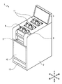
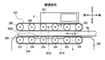
- a cash center of a financial institution or the like has a banknote arranging device 1 installed.
- the banknote sorting device 1 sorts banknotes in accordance with the operation of a financial institution staff or the like (hereinafter referred to as an operator).
- the direction toward the front facing the operator is defined as the front direction
- the opposite is defined as the rear direction
- the left and right direction and the up and down direction when viewed facing the front side of the banknote organizing device 1 are defined. Each is defined and explained.
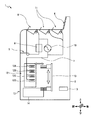
- the transport unit 7 When the transport unit 7 receives the banknote from the banknote take-in unit 5, the transport unit 7 transports the banknote to the discrimination unit 8.
- the discriminating unit 8 discriminates the denomination, authenticity, front and back, the degree of damage, and the like of the bill while conveying the bill inside, and notifies the control unit 3 of the discrimination result.
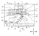
- the direction from the right side to the left side in the figure is the front direction
- the direction from the left side to the right side in the figure is the rear direction
- the direction from the front side to the back side in the figure is the left direction
- from the back side to the front side in the figure is defined as the right direction.
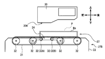
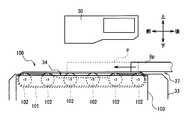
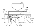
- the banknote binding unit 14 is provided with a conveyance path 27 extending in the front-rear direction above the roller 22D.
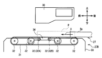
- the banknote binding section 14 first converts the banknote bundle Bp carried into the transport path 27 from the rear end side of the transport path 27 to the upper transport belt 28. It is clamped between the lower conveyor belt 31.
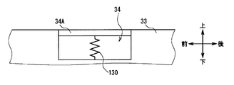
- the lower conveyance belt 31 positioned on the right extension of the depression 34 as if the depression 34 extends from the left end to the right end of the conveyance path 27. And two retracting rollers 32A and 32B are retracted downward. A retraction mechanism for retreating these will be described later.
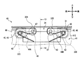
- the rear retracting roller 32B is also urged upward by the torsion spring 48 and supports the lower conveying belt 31 from below.
- the torsion spring 48 may be attached not only to the right end of the shaft 42 of the rear roller 32D but also to the left end.
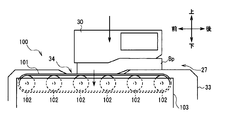
- a part of the lower conveyance belt 31, the front side retracting roller 32A, and the rear side retracting roller 32B have the lower surface front part of the banknote bundle Bp as the upper guide 30 presses the upper surface front part of the banknote bundle Bp.
- the retracting mechanism 40 is operated by this force to retract downward.
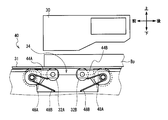
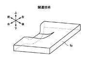
- the banknote bundling portion 14 can bend the banknote bundle Bp in a step shape as a whole so as to have a crease along the longitudinal direction, and can be bound by the paper band 20 in this state.
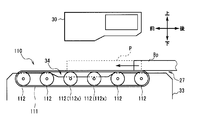
- the lower conveying belt 101 and the plurality of rollers 102 move downward together with the frame 103. Therefore, when the lower conveying belt 101 and the plurality of rollers 102 are retracted, the lower conveying belt 101 and the plurality of rollers 102 move downward. It is also possible to prevent the side conveyance belt 101 from extending.
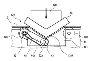
- FIG. 15A and FIG. 15B show an upper guide 120, a lower guide 121, and a retracting mechanism 122 according to the fourth embodiment.
- FIG. 15A and FIG. 15B the same parts as those in the first embodiment are denoted by the same reference numerals.
- a portion of the entire lower conveyance belt 31 that is located on the extension of the recess 121A and the retraction roller 32A can retreat downward.
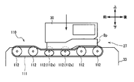
- the frame 103 is divided into a first frame that supports the roller 102 that is positioned on the right side of the recess 34 and a second frame that supports the other roller 102, and only the first frame is By moving downward, among the plurality of rollers 102, only the roller 102 positioned on the right-hand extension from the recess 34 may be retracted.
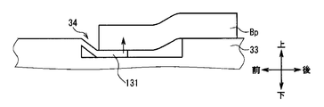
- the banknote bundle Bp is bent in a step shape with the tip of the leaf spring member 131 entering under the front part of the lower surface.
- the lower side conveyance belt 31 and the some roller which supports the lower side conveyance belt 31 as an example of the 2nd surface side conveyance part located in the 2nd surface side of a banknote bundle. 32.
- the present invention is not limited to this, and a pressing portion having a configuration different from that of the upper guide 30 may be used as long as the upper guide 30 functions as a pressing portion.
- a pressing portion having a configuration different from that of the upper guide 30 may be used as long as the upper guide 30 functions as a pressing portion. The same applies to the second to fourth embodiments.
Landscapes
- Engineering & Computer Science (AREA)
- Mechanical Engineering (AREA)
- Physics & Mathematics (AREA)
- General Physics & Mathematics (AREA)
- Basic Packing Technique (AREA)
Priority Applications (1)
| Application Number | Priority Date | Filing Date | Title |
|---|---|---|---|
| CN201380060895.1A CN104822594B (zh) | 2012-12-05 | 2013-11-06 | 介质捆扎装置及介质整理装置 |
Applications Claiming Priority (2)
| Application Number | Priority Date | Filing Date | Title |
|---|---|---|---|
| JP2012266258A JP6064562B2 (ja) | 2012-12-05 | 2012-12-05 | 媒体結束装置 |
| JP2012-266258 | 2012-12-05 |
Publications (1)
| Publication Number | Publication Date |
|---|---|
| WO2014087787A1 true WO2014087787A1 (ja) | 2014-06-12 |
Family
ID=50883214
Family Applications (1)
| Application Number | Title | Priority Date | Filing Date |
|---|---|---|---|
| PCT/JP2013/080046 Ceased WO2014087787A1 (ja) | 2012-12-05 | 2013-11-06 | 媒体結束装置及び媒体整理装置 |
Country Status (3)
| Country | Link |
|---|---|
| JP (1) | JP6064562B2 (enExample) |
| CN (1) | CN104822594B (enExample) |
| WO (1) | WO2014087787A1 (enExample) |
Citations (5)
| Publication number | Priority date | Publication date | Assignee | Title |
|---|---|---|---|---|
| GB2049607A (en) * | 1979-03-28 | 1980-12-31 | Tokyo Shibaura Electric Co | Paper sheet bundling apparatus |
| JPS61203320A (ja) * | 1985-02-25 | 1986-09-09 | グローリー工業株式会社 | 紙葉類結束装置 |
| JPS6335930Y2 (enExample) * | 1981-11-18 | 1988-09-22 | ||
| EP0941930A1 (de) * | 1998-03-11 | 1999-09-15 | Ferag Verpakkingstechniek B.V. | Verfahren und Vorrichtung zum Umreifen von Stapeln |
| JP2011165100A (ja) * | 2010-02-12 | 2011-08-25 | Oki Electric Industry Co Ltd | 紙幣整理装置 |
Family Cites Families (4)
| Publication number | Priority date | Publication date | Assignee | Title |
|---|---|---|---|---|
| US4457126A (en) * | 1979-03-28 | 1984-07-03 | Tokyo Shibaura Denki Kabushiki Kaisha | Paper sheet bundling apparatus |
| CN2138096Y (zh) * | 1992-10-09 | 1993-07-14 | 郝稳企业有限公司 | 数钞机的捆钞装置 |
| CN2755007Y (zh) * | 2003-06-10 | 2006-02-01 | 上海古鳌电子机械有限公司 | 纸币扎把机平缩压币腔及其传动机构 |
| US8567156B2 (en) * | 2009-06-15 | 2013-10-29 | Kabushiki Kaisha Toshiba | Paper sheet processing system |
-
2012
- 2012-12-05 JP JP2012266258A patent/JP6064562B2/ja not_active Expired - Fee Related
-
2013
- 2013-11-06 WO PCT/JP2013/080046 patent/WO2014087787A1/ja not_active Ceased
- 2013-11-06 CN CN201380060895.1A patent/CN104822594B/zh not_active Expired - Fee Related
Patent Citations (6)
| Publication number | Priority date | Publication date | Assignee | Title |
|---|---|---|---|---|
| GB2049607A (en) * | 1979-03-28 | 1980-12-31 | Tokyo Shibaura Electric Co | Paper sheet bundling apparatus |
| US4412411A (en) * | 1979-03-28 | 1983-11-01 | Tokyo Shibaura Denki Kabushiki Kaisha | Paper sheet bundling apparatus |
| JPS6335930Y2 (enExample) * | 1981-11-18 | 1988-09-22 | ||
| JPS61203320A (ja) * | 1985-02-25 | 1986-09-09 | グローリー工業株式会社 | 紙葉類結束装置 |
| EP0941930A1 (de) * | 1998-03-11 | 1999-09-15 | Ferag Verpakkingstechniek B.V. | Verfahren und Vorrichtung zum Umreifen von Stapeln |
| JP2011165100A (ja) * | 2010-02-12 | 2011-08-25 | Oki Electric Industry Co Ltd | 紙幣整理装置 |
Also Published As
| Publication number | Publication date |
|---|---|
| JP2014111465A (ja) | 2014-06-19 |
| CN104822594B (zh) | 2016-09-21 |
| JP6064562B2 (ja) | 2017-01-25 |
| CN104822594A (zh) | 2015-08-05 |
Similar Documents
| Publication | Publication Date | Title |
|---|---|---|
| KR101478445B1 (ko) | 용지류 처리 장치 | |
| KR101156990B1 (ko) | 지폐 식별 계수기 | |
| WO2014071744A1 (zh) | 一种纸页类介质堆叠装置 | |
| JP5018414B2 (ja) | 媒体結束装置 | |
| WO2014187176A1 (zh) | 一种钞票堆叠装置 | |
| JP5418271B2 (ja) | 紙幣整理装置 | |
| CN102930639A (zh) | 一种纸页类堆叠装置 | |
| JP2013050830A (ja) | 紙幣整位機構および紙幣処理装置 | |
| JP6561530B2 (ja) | 記録材折り増し装置、記録材綴じ処理装置、および画像形成システム | |
| JP5978864B2 (ja) | 媒体集積装置及び媒体処理装置 | |
| JP4227613B2 (ja) | 紙葉類処理装置 | |
| JPWO2017130302A1 (ja) | 紙葉類搬送機構及び紙葉類取扱装置 | |
| JP6064562B2 (ja) | 媒体結束装置 | |
| JP4715656B2 (ja) | 媒体処理装置 | |
| KR101545480B1 (ko) | 현금 및 수표 입금 장치 | |
| EP1760018B1 (en) | Paper sheet stacking apparatus | |
| RU2646556C1 (ru) | Устройство обработки бумажных листов | |
| JP5176739B2 (ja) | 紙幣処理装置及び金銭処理機 | |
| JP5433382B2 (ja) | 紙葉類処理システム | |
| JP4134153B2 (ja) | 紙葉類結束装置 | |
| JP4206096B2 (ja) | 紙葉類結束装置 | |
| JP6851253B2 (ja) | 紙葉類処理装置 | |
| JP5540881B2 (ja) | 用紙押さえ装置、用紙折り装置、及び画像形成装置 | |
| JP2008046804A (ja) | 紙葉類整理装置 | |
| WO2013014698A1 (ja) | 紙葉類処理装置、紙葉類収納装置 |
Legal Events
| Date | Code | Title | Description |
|---|---|---|---|
| 121 | Ep: the epo has been informed by wipo that ep was designated in this application |
Ref document number: 13861397 Country of ref document: EP Kind code of ref document: A1 |
|
| NENP | Non-entry into the national phase |
Ref country code: DE |
|
| 122 | Ep: pct application non-entry in european phase |
Ref document number: 13861397 Country of ref document: EP Kind code of ref document: A1 |