WO2014084336A1 - インクジェット印刷装置および印刷方法 - Google Patents
インクジェット印刷装置および印刷方法 Download PDFInfo
- Publication number
- WO2014084336A1 WO2014084336A1 PCT/JP2013/082150 JP2013082150W WO2014084336A1 WO 2014084336 A1 WO2014084336 A1 WO 2014084336A1 JP 2013082150 W JP2013082150 W JP 2013082150W WO 2014084336 A1 WO2014084336 A1 WO 2014084336A1
- Authority
- WO
- WIPO (PCT)
- Prior art keywords
- nozzle row
- effective
- nmax
- effective nozzle
- nozzle
- Prior art date
- Legal status (The legal status is an assumption and is not a legal conclusion. Google has not performed a legal analysis and makes no representation as to the accuracy of the status listed.)
- Ceased
Links
Images



Classifications
-
- B—PERFORMING OPERATIONS; TRANSPORTING
- B41—PRINTING; LINING MACHINES; TYPEWRITERS; STAMPS
- B41J—TYPEWRITERS; SELECTIVE PRINTING MECHANISMS, i.e. MECHANISMS PRINTING OTHERWISE THAN FROM A FORME; CORRECTION OF TYPOGRAPHICAL ERRORS
- B41J2/00—Typewriters or selective printing mechanisms characterised by the printing or marking process for which they are designed
- B41J2/005—Typewriters or selective printing mechanisms characterised by the printing or marking process for which they are designed characterised by bringing liquid or particles selectively into contact with a printing material
- B41J2/01—Ink jet
- B41J2/015—Ink jet characterised by the jet generation process
- B41J2/04—Ink jet characterised by the jet generation process generating single droplets or particles on demand
- B41J2/045—Ink jet characterised by the jet generation process generating single droplets or particles on demand by pressure, e.g. electromechanical transducers
- B41J2/04501—Control methods or devices therefor, e.g. driver circuits, control circuits
- B41J2/04568—Control according to number of actuators used simultaneously
-
- B—PERFORMING OPERATIONS; TRANSPORTING
- B41—PRINTING; LINING MACHINES; TYPEWRITERS; STAMPS
- B41J—TYPEWRITERS; SELECTIVE PRINTING MECHANISMS, i.e. MECHANISMS PRINTING OTHERWISE THAN FROM A FORME; CORRECTION OF TYPOGRAPHICAL ERRORS
- B41J2/00—Typewriters or selective printing mechanisms characterised by the printing or marking process for which they are designed
- B41J2/005—Typewriters or selective printing mechanisms characterised by the printing or marking process for which they are designed characterised by bringing liquid or particles selectively into contact with a printing material
- B41J2/01—Ink jet
- B41J2/21—Ink jet for multi-colour printing
- B41J2/2132—Print quality control characterised by dot disposition, e.g. for reducing white stripes or banding
- B41J2/2139—Compensation for malfunctioning nozzles creating dot place or dot size errors
-
- B—PERFORMING OPERATIONS; TRANSPORTING
- B41—PRINTING; LINING MACHINES; TYPEWRITERS; STAMPS
- B41J—TYPEWRITERS; SELECTIVE PRINTING MECHANISMS, i.e. MECHANISMS PRINTING OTHERWISE THAN FROM A FORME; CORRECTION OF TYPOGRAPHICAL ERRORS
- B41J2/00—Typewriters or selective printing mechanisms characterised by the printing or marking process for which they are designed
- B41J2/005—Typewriters or selective printing mechanisms characterised by the printing or marking process for which they are designed characterised by bringing liquid or particles selectively into contact with a printing material
- B41J2/01—Ink jet
- B41J2/015—Ink jet characterised by the jet generation process
- B41J2/04—Ink jet characterised by the jet generation process generating single droplets or particles on demand
- B41J2/045—Ink jet characterised by the jet generation process generating single droplets or particles on demand by pressure, e.g. electromechanical transducers
- B41J2/04501—Control methods or devices therefor, e.g. driver circuits, control circuits
- B41J2/04586—Control methods or devices therefor, e.g. driver circuits, control circuits controlling heads of a type not covered by groups B41J2/04575 - B41J2/04585, or of an undefined type
Definitions
- the present invention relates to an inkjet printing apparatus and a printing method, and more particularly to an inkjet printing apparatus and a printing method for performing printing using a print head having a nozzle row in which a plurality of nozzles are arranged.
- the present invention has been made in view of the above problems, and provides a technique for reducing band stripes during printing using a print head having a nozzle array and obtaining a higher quality printed image. Main purpose.
- an inkjet printing apparatus selects a print head having a nozzle row in which a plurality of nozzles are arranged, and a plurality of nozzles that are continuously arranged in a part of the nozzle row as an effective nozzle row.
- a nozzle selection unit that performs scanning, a main scanning control unit that scans the print head in a main scanning direction that intersects the nozzle row, and a relative relative to the print head in a sub-scanning direction that is parallel to the direction in which the nozzle row extends.
- Sub-scanning control means for moving the printing medium in general, and the main scanning control means scans the print head in the main scanning direction, and the effective nozzle row and at least one end of the effective nozzle row And at least one nozzle that extends discontinuously from the printing medium by ejecting ink onto the printing medium.
- Each for discharging a set number of times ink is characterized in that the shift amount from one end of the nozzle row of the effective nozzle row reselect the effective nozzle columns as modified.
- the nozzle selection unit changes the shift amount (position) of the effective nozzle row that ejects ink during printing, the boundary between the bands is dispersed back and forth in the sub-scanning direction. Stripes can be reduced.
- ink is ejected only from an effective nozzle row composed of a plurality of nozzles arranged continuously in a part of the nozzle row
- vertical lines may be noticeable in the obtained print image.
- ink is ejected from the nozzles extending discontinuously from at least one end of the effective nozzle row in addition to the effective nozzle row. Therefore, an intermediate region printed by discontinuous nozzles can be provided between portions printed by continuous nozzles (effective nozzle rows) in a vertical line in the printed image. Thereby, it is possible to eliminate the conspicuous vertical line. Therefore, a higher quality printed image can be obtained.
- the nozzle selection unit selects the effective nozzle row so that the number of nozzles of the effective nozzle row is Z and the difference +1 between the minimum value and the maximum value of the shift amount is Nmax.
- Nmax and Z are preferably parameters that can be changed.
- Nmax and Z are parameters that can be changed, printing according to desired printing conditions can be performed. That is, the number of nozzles in the effective nozzle row corresponds to the width of the band, and the difference between the minimum value and the maximum value of the shift amount corresponds to the overlapping width of the bands.
- the band width can be lengthened and the overlapping width between bands can be shortened to improve the printing speed.
- the print quality can be improved by increasing the ratio of the overlapping width of the bands to the width of the bands by increasing Nmax and decreasing Z.
- the nozzle selection unit selects the effective nozzle row so that a difference +1 between the minimum value and the maximum value of the shift amount is Nmax, and the Nmax is expressed by the following equation: It is preferable to satisfy (1).
- Nmax ⁇ 0.1 ⁇ L / (P + 1) (1)
- L indicates the total number of nozzles included in the nozzle row
- P indicates the number of printing passes.
- the difference between the minimum value and the maximum value of the shift amount corresponds to the overlapping width of the bands. For this reason, if the difference between the minimum value and the maximum value of the shift amount is small, it may appear like a band. This is particularly noticeable when the total number of nozzles included in the nozzle row is large and the number of printing passes is small.
- Nmax which is a difference +1 between the minimum value and the maximum value of the shift amount, as shown in the above equation (1), it can be made difficult to look like a band. Therefore, a higher quality printed image can be obtained.
- the nozzle selecting unit is configured such that the difference +1 between the minimum value and the maximum value of the shift amount is Nmax (Nmax ⁇ 4), and the shift at each time when the effective nozzle row is reselected Nmax times.
- the effective nozzle row is selected so that the total amount of change in the amount becomes [(Nmax / 2) 2 + ⁇ (Nmax / 2) -1 ⁇ 2 + (Nmax-1)] / 2 or more. It is preferable that
- the change in the position of the end of the effective nozzle row can be made a high frequency. This is because the shift amount corresponds to the position of the end portion of the effective nozzle row, and the change in the position of the end portion of the effective nozzle row that prints adjacent positions increases as the total amount of change amount of the shift amount increases. Because it becomes.
- the change in the position of the end of the effective nozzle row is a low frequency, for example, when the position of the effective nozzle row is shifted one by one, the pattern formed by the end of the effective nozzle row is continuous. It becomes easy to be recognized by the eyes.
- the change in the position of the end portion of the effective nozzle row can be made a high frequency, so that the pattern formed by the end portion of the effective nozzle row is hardly recognized by human eyes. be able to. Therefore, a higher quality printed image can be obtained.
- a printing method according to the present invention is a printing method using an inkjet printing apparatus including a print head having a nozzle row in which a plurality of nozzles are arranged, and the plurality of nozzles arranged in succession in a part of the nozzle rows are effectively used.
- a nozzle selection step for selecting as a nozzle row, and causing the print head to scan in a main scanning direction intersecting the nozzle row, and extending discontinuously from at least one end of the effective nozzle row and the effective nozzle row
- a nozzle reselecting step for changing the shift amount from the end, and moving the print medium relative to the print head in a sub-scanning direction parallel to the direction in which the nozzle row extends. It is characterized in that it comprises a sub-scanning step of, the.
- the ink jet printing apparatus may be realized by a computer.
- the ink jet printing apparatus is operated by the computer by operating the computer as each unit included in the ink jet printing apparatus.
- a control program for an inkjet printing apparatus to be realized and a computer-readable recording medium on which the control program is recorded also fall within the scope of the present invention.
- the band stripe at the time of printing using the printing head which has a nozzle row can be reduced, a vertical line can be suppressed and a higher quality printed image can be obtained. There is an effect.
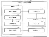
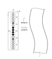
- FIG. 1 is a functional block diagram showing a schematic configuration of an inkjet printing apparatus according to an embodiment of the present invention. It is a schematic diagram which shows schematic structure of a print head.
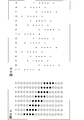
- FIG. 3A is a diagram illustrating an example of selection of an effective nozzle row
- FIG. 3B is a diagram illustrating an example of an area printed by scanning the same line.
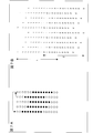
- FIG. 4A is a diagram illustrating an example of an area printed by scanning a plurality of lines
- FIG. 4B is a diagram in which a part thereof is taken out.
- FIG. 5A to FIG. 5C are diagrams for explaining variations of nozzle positions for ejecting ink.
- FIG. 6A is a diagram illustrating an example of selection of an effective nozzle row in each scan when performing multi-pass printing
- FIG. 6A is a diagram illustrating an example of selection of an effective nozzle row in each scan when performing multi-pass printing
- FIG. 6B is a diagram illustrating an example of a region to be printed in each scan.
- FIG. 7A is a diagram showing another example of the selection pattern of the effective nozzle row
- FIG. 7B is a pattern shown in FIG. 7A, showing the area printed on the print medium when the effective nozzle row is reselected. It is a figure which shows an example.
- FIG. 8A is a diagram illustrating still another example of the selection pattern of the effective nozzle row
- FIG. 8B is an area printed on the print medium when the effective nozzle row is reselected in the pattern illustrated in FIG. 8A. It is a figure which shows the example of.
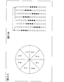
- FIG. 9A shows the pie chart corresponding to the effective nozzle row shown in Drawing 9B.
- 10A to 10E are diagrams illustrating examples for explaining an algorithm for selecting an effective nozzle row according to the present embodiment.
- FIG. 1 is a functional block diagram showing a schematic configuration of an inkjet printing apparatus 10 according to an embodiment of the present invention.
- the inkjet printing apparatus 10 includes a carriage 11, a conveyance roller 12, a print head 20, and a control unit 30.
- the control unit 30 includes a main scanning control unit (main scanning control unit) 31, a sub scanning control unit (sub scanning control unit) 32, a nozzle selection unit (nozzle selection unit) 33, and a discharge control unit 34.
- the carriage 11 has a print head 20 and is configured to be movable.
- the main scanning control unit 31 controls the carriage 11 to scan the print head 20 in the main scanning direction.
- the conveyance roller 12 is configured to be able to convey the print medium 1 (see FIG. 2) to be printed.
- the sub-scanning control unit 32 controls the transport roller 12 to move the print medium 1 in the sub-scanning direction orthogonal to the main scanning direction relative to the print head 20.
- FIG. 2 is a schematic diagram showing a schematic configuration of the print head 20.
- the print head 20 has a nozzle row 22 in which a plurality of nozzles 21 are arranged.
- the nozzle row 22 extends in a direction perpendicular to the main scanning direction and parallel to the sub-scanning direction.
- the nozzle 21 is configured to eject ink droplets.
- the number of nozzle rows 22 provided in the recording head 20 is not limited to one, and a plurality of nozzle rows may be provided.
- the main scanning control unit 31 scans the print head 20 in the main scanning direction, and the ejection control unit 34 ejects ink onto the printing medium 1 from some nozzles 21 of the printing head 20 to perform printing. Executed.
- ink discharge nozzles that discharge ink are shown in black and gray, and ink non-discharge nozzles that do not discharge ink are shown in white.
- ink droplets corresponding to the print image to be printed are ejected in accordance with the position on the print medium 1 where the ink droplets ejected from each land.
- ink is not ejected from the ink non-ejection nozzles.
- the ink discharge nozzles are discontinuous from an effective nozzle row 23 composed of a plurality of nozzles 21 (black) continuously arranged in a part of the nozzle row 22 and at least one end of the effective nozzle row 23. And at least one nozzle 21 (gray) extending in the direction.
- the nozzle 21 of the nozzle row 22 includes an effective nozzle row 23, a dotted line portion 24 that extends discontinuously from at least one end portion thereof, and an ink non-ejection portion 25 including an ink non-ejection nozzle. Is done.
- the effective nozzle row 23 includes the nozzles 21 selected by the nozzle selection unit 33.
- the nozzle selection unit 33 selects a plurality of nozzles 21 continuously arranged in a part of the nozzle row 22 as the effective nozzle row 23.
- the discharge control unit 34 includes the effective nozzle row 23 selected by the nozzle selection unit 33 and at least one nozzle 21 that discontinuously extends from at least one end of the effective nozzle row 23 (the nozzle 21 shown in gray in FIG. 2). ) Ink is discharged.
- the nozzle selection unit 33 changes the effective nozzle so that the shift amount from one end of the nozzle row 22 of the effective nozzle row 23 is changed every time the effective nozzle row 23 ejects ink for a preset number of times. Reselect column 23.
- the amount of displacement of the effective nozzle row 23 from one end portion of the nozzle row 22 means how much the end portion on the same side of the effective nozzle row 23 is from one end portion of the nozzle row 22. This is a value representing the deviation by the number of nozzles. For example, in the example shown in FIG.
- FIG. 3A is a diagram illustrating an example of selection of the effective nozzle row 23 by the nozzle selection unit 33.
- the nozzle selection unit 33 changes the shift amount with eight patterns as one cycle, for example.
- FIG. 3B shows a scan of the same line when the effective nozzle row 23 is reselected (changes the position of the effective nozzle row 23) in the pattern shown in FIG. 3A every time the effective nozzle row 23 ejects ink once.
- FIG. 6 is a diagram illustrating an example of a region printed on the print medium 1. As shown in FIG. 3B, printing is performed while the end of the effective nozzle row 23 is shifted. In addition, ink is ejected at discontinuous positions from the end of the effective nozzle row 23.
- the main scanning direction corresponds to the horizontal direction of the paper and the sub-scanning direction corresponds to the vertical direction of the paper.
- the sub scanning control unit 32 moves the print medium 1 relative to the print head 20 in the sub scanning direction.
- a plurality of bands can be printed on the print medium 1.
- the printable range in the scanning of the first to third lines is shown on the left side of the drawing.
- a plurality of bands printed by the first to third line scans are shown on the right side of the figure (the numbers in the figure indicate the positions printed by the line scans). Yes.)
- the boundaries between the bands are dispersed back and forth in the sub-scanning direction.
- the nozzle selection unit 33 when printing, changes the shift amount (position) of the effective nozzle row 23 that ejects ink, so that the boundary between the bands is changed before and after the sub-scanning direction. It is possible to disperse and reduce band fringes.
- FIG. 4B is a diagram in which one vertical line is extracted from the area shown in FIG. 4A.
- the area A printed by the effective nozzle row 23 composed of the continuous nozzles 21 and the intermediate area printed by the discontinuous nozzles between the areas A of different bands. B exists.
- the intermediate region B can be provided by complementing the region printed by the nozzles 21 extending discontinuously. Due to the presence of the intermediate region B, it is possible to prevent the vertical lines from being noticeable more than necessary, and to obtain a higher quality printed image.
- the at least one nozzle 21 extending discontinuously from at least one end of the effective nozzle row 23 is not limited to the case of extending from both ends of the effective nozzle row 23 as shown in FIG.
- the effective nozzle row 23 may extend from one end.
- the end of the effective nozzle row 23 that extends the nozzle 21 may be changed alternately every time the scanning line is advanced so as to complement the intermediate region B from both sides.
- the at least one nozzle 21 extending discontinuously from at least one end of the effective nozzle row 23 is not limited to the case where only one nozzle 21 extends as shown in FIG.
- two or more nozzles 21 may extend from the end of the effective nozzle row 23.
- FIG. 5B shows the nozzle 21 that complements the intermediate region B from both sides.
- At least one nozzle 21 extending discontinuously from at least one end of the effective nozzle row 23 is naturally limited to a case where it extends from the end of the effective nozzle row 23 by one as shown in FIG. Not.
- two or more nozzles 21 may extend from the end of the effective nozzle row 23, and if not connected to the effective nozzle row 23, two or more nozzles 21 It may be continuous.
- FIG. 5C shows the nozzle 21 that complements the intermediate region B from both sides.
- FIGS. 4A and 4B As long as printing can be performed as shown in FIGS. 4A and 4B, the number of printing passes is not limited. When printing in multi-pass, for example, printing can be performed as shown in FIGS. 6A and 6B.
- FIGS. 6A and 6B are diagrams illustrating a case where the same line is scanned eight times.
- the nozzle selection unit 33 selects the effective nozzle row 23 while shifting one by one.
- the numbers described in the upper part of the figure indicate the effective nozzle row 23 in the number of scans. Then, by selecting a printing position in each scan as shown in FIG. 6B, printing equivalent to that in FIGS. 4A and 4B can be performed. It should be noted that the numbers described in the upper part of FIG. 6B indicate how many times the print area is printed. In this case, the nozzle selection unit 33 reselects the effective nozzle row 23 every time the effective nozzle row 23 ejects ink the number of times corresponding to one scan.
- the nozzle selection unit 33 only needs to change the position of the effective nozzle row 23, and the shift amount at each time is not particularly limited. However, the nozzle selection unit 33 can obtain a more preferable result by changing the position of the effective nozzle row 23 under the following conditions.
- the nozzle selection unit 33 sets the number of nozzles in the effective nozzle row 23 to be effective.
- the difference between the maximum value (9: second from the left in FIG. 3A) and the minimum value (2: first from the left in FIG. 3A) of the shift amount from one end of the nozzle row 22 of the nozzle row 23 is set to 7.
- the effective nozzle row 23 is selected.
- the number of nozzles in the effective nozzle array 23 is increased (8), and the difference between the maximum value and the minimum value of the shift amount is reduced (4), thereby enabling faster printing. It can be performed.
- the number of nozzles in the effective nozzle row 23 corresponds to the band width
- the difference between the minimum value and the maximum value of the shift amount corresponds to the overlapping width of the bands. Therefore, by increasing the number of nozzles of the effective nozzle row 23 and reducing the difference between the maximum value and the minimum value of the shift amount, the band width is increased, and the overlapping width between the bands is shortened to improve the printing speed. Can do.
- FIG. 7A is a diagram showing a selection pattern of the effective nozzle row 23, and FIG. 7B is a pattern shown in FIG. 7A when the effective nozzle row 23 is reselected (the position of the effective nozzle row 23 is changed).
- FIG. 3 is a diagram illustrating an example of an area printed on a print medium 1.
- FIGS. 8A and 8B the number of nozzles in the effective nozzle array 23 is further increased (9), and the difference between the maximum value and the minimum value of the shift amount is further reduced (3), thereby further increasing the printing speed. It can be performed.
- 8A is a diagram showing a selection pattern of the effective nozzle row 23, and
- FIG. 8B is a pattern shown in FIG. 8A when the effective nozzle row 23 is reselected (the position of the effective nozzle row 23 is changed).
- FIG. 3 is a diagram illustrating an example of an area printed on a print medium 1.
- the number of nozzles in the effective nozzle row 23 is reduced, By increasing the difference from the minimum value, it is possible to increase the ratio of the overlapping width of the bands to the width of the bands, and to perform higher quality printing.
- desired printing can be performed by appropriately changing the number of nozzles of the effective nozzle row 23 and the difference between the maximum value and the minimum value of the shift amount from one end of the nozzle row 22 of the effective nozzle row 23.
- Printing that meets the conditions can be performed.
- the inkjet printing apparatus 10 (the control unit 30 thereof) has parameters Nmax and Z, and the nozzle selection unit 33 sets the number of nozzles in the effective nozzle row 23 to Z, and the minimum value and maximum value of the shift amount are set as follows. If the effective nozzle row 23 is selected so that the difference +1 becomes Nmax, printing according to the printing conditions can be performed successfully.
- Nmax and Z are parameters that can be changed, printing can be performed under printing conditions required by the user. Nmax and Z may be changed every time printing is performed or during printing. The present embodiment is not limited to this, and the control unit 30 may automatically set Nmax and Z, and Nmax and Z may be fixed values set in advance.
- Nmax so as to satisfy the following formula (1).
- Nmax ⁇ 0.1 ⁇ L / (P + 1) (1)
- L indicates the total number of nozzles included in the nozzle row
- P indicates the number of printing passes.
- the number P of printing passes refers to “the number of scans necessary to complete a print image on a certain area”.
- Nmax 8 or more.
- the upper limit value of Nmax is not particularly limited, but is preferably 0.9 ⁇ L / (P + 1) or less.
- the nozzle selection unit 33 further calculates that the total change amount of the shift amount at each time when the effective nozzle row 23 is reselected Nmax times is [(Nmax / 2) 2 + ⁇ (Nmax / 2) ⁇ 1]. ⁇ 2 + (Nmax ⁇ 1)] / 2 or more (however, Nmax ⁇ 4) is preferably selected so that the effective nozzle row 23 is selected.
- Nmax is 8
- [(Nmax / 2) 2 + ⁇ (Nmax / 2) ⁇ 1 ⁇ 2 + (Nmax ⁇ 1) )] / 2 is 16.
- the amount of change in the shift amount at each time when Nmax is reselected is 7, 4, 1, 3, 5, 4, 3, 5 and the total is 32.
- the change in the position of the end of the effective nozzle row 23 can be made a high frequency. This is because the shift amount corresponds to the position of the end portion of the effective nozzle row 23, and the change in the position of the end portion of the effective nozzle row 23 that prints adjacent positions increases as the total amount of change amount of the shift amount increases. This is because it becomes larger.
- the change in the position of the end portion of the effective nozzle row 23 a high frequency the pattern formed by the end portion of the effective nozzle row 23 can be made difficult to be recognized by human eyes.
- Such a method of selecting the effective nozzle row 23 can be executed by the following algorithm, for example.
- FIGS. 9A and 9B are diagrams illustrating an example for explaining the present algorithm.
- a to H in the pie chart shown in FIG. 9A correspond to the effective nozzle rows 23 of A to H shown in FIG. 9B.
- the numbers 1 to 8 in FIG. 9A indicate the order when the effective nozzle rows 23 in FIG. 9B are arranged in ascending order of the shift amount. In the examples of FIGS. 9A and 9B, they are equal to the shift amount ⁇ 1. .
- FIG. 9A First, in FIG. 9A, (i) 1 is put into A. And (ii) when entering an even numbered (2, 4, 6, 8th) number, put it in the diagonal position of the previous number (for example, 2 is on the diagonal line of A containing 1) E). (Iii) When entering odd-numbered (3, 5, 7th) numbers, (iii-A) a semicircle arbitrarily divided in advance (for example, a semicircle composed of A to C and H, and D to G) In the semicircle that contains the previous number in the semicircle that is farthest from the previous number (for example, 3 is in the semicircle consisting of D to G that contains 2) In G, the furthest away from 2). By repeating this, the pattern shown in FIG.
- the nozzle selection unit 33 selects the effective nozzle rows 23 in the order of 1, 8, 4, 5, 2, 7, 3, and 6 obtained in this way, so that the effective nozzle rows 23 that print adjacent positions are mutually connected.
- the change in the position of is the largest. Therefore, by making the change in the position of the end portion of the effective nozzle row 23 a high frequency, the pattern formed by the end portion of the effective nozzle row 23 can be made difficult to be recognized by human eyes. In the case shown in FIG.
- 10A to 10E are diagrams showing patterns of the effective nozzle row 23 selected by the same algorithm as in FIGS. 9A and 9B.
- the sum of the left and right semicircles matches 5.
- the sum of the numbers in the left and right semicircles matches 68
- the sum of the four divided parts matches 34.
- the sum of the numbers in the left and right semicircles matches 68. Also in these patterns, as in the patterns of FIGS.
- the total amount of change in the shift amount at each time when the effective nozzle row 23 is reselected Nmax times is [(Nmax / 2) 2 + ⁇ (Nmax / 2) -1 ⁇ 2 + (Nmax-1)] / 2 or more (where Nmax ⁇ 4), and the change in the position of the end portion of the effective nozzle row 23 can be a high frequency.
- the control block (particularly the main scanning control unit 31, the sub scanning control unit 32, the nozzle selection unit 33, and the ejection control unit 34) of the inkjet printing apparatus 10 is a logic circuit (hardware) formed in an integrated circuit (IC chip) or the like. It may be realized by software, or may be realized by software using a CPU (Central Processing Unit).
- the inkjet printing apparatus 10 includes a CPU that executes instructions of a program that is software that realizes each function, and a ROM (Read Only Memory) in which the program and various data are recorded so as to be readable by the computer (or CPU).
- a storage device (these are referred to as “recording media”), a RAM (Random Access Memory) for expanding the program, and the like are provided.
- the objective of this invention is achieved when a computer (or CPU) reads the said program from the said recording medium and runs it.
- a “non-temporary tangible medium” such as a tape, a disk, a card, a semiconductor memory, a programmable logic circuit, or the like can be used.
- the program may be supplied to the computer via an arbitrary transmission medium (such as a communication network or a broadcast wave) that can transmit the program.
- a transmission medium such as a communication network or a broadcast wave
- the present invention can also be realized in the form of a data signal embedded in a carrier wave in which the program is embodied by electronic transmission.
- the inkjet printing apparatus 10 selects, as an effective nozzle row 23, a print head 20 having a nozzle row 22 in which a plurality of nozzles 21 are arranged, and a plurality of nozzles 21 that are continuously arranged in a part of the nozzle row 22.
- a sub-scanning control unit 32 that relatively moves the print medium 1, and the main scanning control unit 31 scans the print head 20 in the main scanning direction, and at least one of the effective nozzle row 23 and the effective nozzle row 23. And at least one nozzle 21 that discontinuously extends from the end of the nozzle to perform printing by ejecting ink onto the print medium 1, and a nozzle selection unit 3 selects the effective nozzle row 23 so that the shift amount from one end of the nozzle row 22 of the effective nozzle row 23 is changed every time the effective nozzle row 23 ejects ink a preset number of times. cure.
- the nozzle selection unit 33 changes the shift amount (position) of the effective nozzle row 23 that ejects ink. , Band fringes can be reduced.
- ink when ink is ejected only from the effective nozzle row 23 including the plurality of nozzles 21 continuously arranged in a part of the nozzle row 22, vertical lines may be conspicuous in the obtained print image.
- ink is ejected from the nozzles 21 that extend discontinuously from at least one end of the effective nozzle row 23 in addition to the effective nozzle row 23. Therefore, an intermediate region printed by the discontinuous nozzles 21 can be provided between portions printed by the continuous nozzles 21 (effective nozzle rows 23) in the vertical lines in the printed image. Thereby, it is possible to eliminate the conspicuous vertical line. Therefore, a higher quality printed image can be obtained.
- the nozzle selection unit 33 selects the effective nozzle array 23 so that the number of nozzles in the effective nozzle array 23 is Z, and the difference +1 between the minimum value and the maximum value of the shift amount is Nmax.
- Nmax and Z can be parameters that can be changed.
- Nmax and Z are parameters that can be changed, printing according to desired printing conditions can be performed. That is, the number of nozzles in the effective nozzle row 23 corresponds to the width of the band, and the difference between the minimum value and the maximum value of the shift amount corresponds to the overlapping width of the bands.
- the band width can be lengthened and the overlapping width between bands can be shortened to improve the printing speed.
- the print quality can be improved by increasing the ratio of the overlapping width of the bands to the width of the bands by increasing Nmax and decreasing Z.
- the nozzle selection unit 33 selects the effective nozzle row 23 so that the difference +1 between the minimum value and the maximum value of the shift amount +1 is Nmax. (1) can be satisfied.
- Nmax ⁇ 0.1 ⁇ L / (P + 1) (1)
- L indicates the total number of nozzles included in the nozzle row 22
- P indicates the number of printing passes.
- the difference between the minimum value and the maximum value of the shift amount corresponds to the overlapping width of the bands. For this reason, if the difference between the minimum value and the maximum value of the shift amount is small, it may appear like a band. This is particularly noticeable when the total number of nozzles included in the nozzle row is large and the number of printing passes is small.
- Nmax which is a difference +1 between the minimum value and the maximum value of the shift amount, as shown in the above equation (1), it can be made difficult to look like a band. Therefore, a higher quality printed image can be obtained.
- the nozzle selection unit 33 determines that the difference +1 between the minimum value and the maximum value of the shift amount is Nmax (Nmax ⁇ 4), and the shift at each time when the effective nozzle row 23 is reselected Nmax times.
- the effective nozzle row 23 is selected so that the total amount of change in the amount becomes [(Nmax / 2) 2 + ⁇ (Nmax / 2) ⁇ 1 ⁇ 2 + (Nmax ⁇ 1)] / 2 or more. Can be.
- the change in the position of the end portion of the effective nozzle row 23 can be made a high frequency. This is because the shift amount corresponds to the position of the end portion of the effective nozzle row 23, and the change in the position of the end portion of the effective nozzle row 23 that prints the adjacent positions as the total value of the change amount of the shift amount increases. This is because it becomes larger.
- the change in the position of the end of the effective nozzle row 23 has a low frequency, for example, when the position of the effective nozzle row 23 is shifted one by one, the pattern formed by the end of the effective nozzle row 23 is continuous. Therefore, it becomes easy to be recognized by human eyes.
- the change in the position of the end portion of the effective nozzle row 23 can be a high frequency, so that the pattern formed by the end portion of the effective nozzle row 23 is recognized by the human eye. Can be difficult. Therefore, a higher quality printed image can be obtained.
- the printing method according to the present embodiment is a printing method using the inkjet printing apparatus 10 including the print head 20 having the nozzle row 22 in which the plurality of nozzles 21 are arranged, and is continuously arranged in a part of the nozzle row 22.
- Nozzle reselection process for changing the shift amount from one end of the nozzle row 22 of the row 23, and sub-scanning parallel to the direction in which the nozzle row 22 extends To direction includes a sub-scanning step of moving relatively the printing medium 1 with respect to the print head 20.
- the present invention can be used in the field of manufacturing inkjet printers.
Landscapes
- Engineering & Computer Science (AREA)
- Quality & Reliability (AREA)
- Ink Jet (AREA)
Abstract
ノズル列(22)を有する印刷ヘッドを用いた印刷の際のバンド縞を低減し、より高品質な印刷画像を得るための技術を提供することを課題とする。 有効ノズル列(23)と、有効ノズル列(23)の少なくとも一方の末端から不連続に延在する少なくとも一つのノズル(24)とが印刷媒体にインクを吐出することにより印刷を行い、該有効ノズル列(23)が予め設定された回数インクを吐出する毎に、該有効ノズル列(23)の該ノズル列(22)の一方の端部からのずらし量が変更されるように上記有効ノズル列(23)を選択し直す。
Description
本発明はインクジェット印刷装置および印刷方法に関するものであり、特に、複数のノズルが並ぶノズル列を有する印刷ヘッドを用いて印刷を行うインクジェット印刷装置および印刷方法に関するものである。
シリアル方式のインクジェット印刷装置では、一回の走査によって形成されるバンド同士が重なってバンド縞(縞模様)が生じるという問題が知られている。この問題を解決するために、ノズル列の一部を、インクを吐出する有効ノズル列として選択し、印刷媒体上を走査するとともに、有効ノズル列の位置を変える技術が開発されている(特許文献1)。
特許文献1に記載の技術よりも高品質な印刷画像を得ることができる印刷技術を提供することができれば非常に有用である。特に、特許文献1に記載の技術では、縦線が目立つ場合があり、これを解消することができれば好ましい。
本発明は、上記課題に鑑みてなされたものであり、ノズル列を有する印刷ヘッドを用いた印刷の際のバンド縞を低減し、より高品質な印刷画像を得るための技術を提供することを主たる目的とする。
上記課題を解決するために、本発明に係るインクジェット印刷装置は、複数のノズルが並ぶノズル列を有する印刷ヘッドと、該ノズル列の一部に連続して並ぶ複数のノズルを有効ノズル列として選択するノズル選択手段と、該ノズル列と交差する主走査方向に、該印刷ヘッドを走査させる主走査制御手段と、該ノズル列が伸びる方向と平行な副走査方向へ、該印刷ヘッドに対して相対的に印刷媒体を移動させる副走査制御手段と、を備え、該主走査制御手段が該印刷ヘッドを該主走査方向に走査させるとともに、該有効ノズル列と、該有効ノズル列の少なくとも一方の末端から不連続に延在する少なくとも一つのノズルとが該印刷媒体にインクを吐出することにより印刷を行うようになっており、該ノズル選択手段は、該有効ノズル列が予め設定された回数インクを吐出する毎に、該有効ノズル列の該ノズル列の一方の端部からのずらし量が変更されるように上記有効ノズル列を選択し直すことを特徴としている。
上記の構成によれば、印刷の際に、インクを吐出する有効ノズル列のずらし量(位置)をノズル選択手段が変化させるため、バンド間の境界を副走査方向の前後に分散して、バンド縞を低減することができる。
ここで、ノズル列の一部に連続して並ぶ複数のノズルからなる有効ノズル列からのみインクを吐出するようにした場合、得られる印刷画像において縦線が目立つ場合がある。これに対し、上記の構成によれば、有効ノズル列に加えて、当該有効ノズル列の少なくとも一方の末端から不連続に延在するノズルとからインクを吐出するようになっている。そのため、印刷画像における縦のラインにおいて、連続するノズル(有効ノズル列)によって印刷される部分同士の間に、不連続なノズルによって印刷される中間領域を設けることができる。これにより、縦線が目立つことを解消することができる。したがって、より高品質な印刷画像を得ることができる。
上記インクジェット印刷装置では、上記ノズル選択手段は、上記有効ノズル列のノズル数がZとなり、上記ずらし量の最小値と最大値との差+1がNmaxとなるように上記有効ノズル列を選択するようになっており、当該NmaxおよびZは、変更可能なパラメータであることが好ましい。
上記の構成によれば、NmaxおよびZが、変更可能なパラメータであるため、希望する印刷条件に応じた印刷を行うことができる。すなわち、有効ノズル列のノズル数は、バンドの幅に対応し、上記ずらし量の最小値と最大値との差は、バンド同士の重なり幅に対応する。例えば、高速な印刷を希望する場合には、Nmaxを小さくし、Zを大きくすることにより、バンドの幅を長くし、バンド同士の重なり幅を短くして印刷速度を向上させることができる。また、高品質な印刷を希望する場合には、Nmaxを大きくし、Zを小さくすることにより、バンドの幅に対するバンド同士の重なり幅の割合を大きくして印刷品質を向上させることができる。
上記インクジェット印刷装置では、上記ノズル選択手段は、上記ずらし量の最小値と最大値との差+1がNmaxとなるように上記有効ノズル列を選択するようになっており、当該Nmaxは、下記式(1)を満たすことが好ましい。
Nmax≧0.1×L/(P+1)・・・(1)
(但し、Lは上記ノズル列に含まれる全ノズル数を示し、Pは印刷のパス数を示す。)
上記ずらし量の最小値と最大値との差は、バンド同士の重なり幅に対応する。そのため、上記ずらし量の最小値と最大値との差が小さいと、帯状に見えてしまう場合がある。これは、特に、ノズル列に含まれる全ノズル数が多く、印刷のパス数が小さい場合に顕著となる。ここで、上記ずらし量の最小値と最大値との差+1となるNmaxを上記式(1)のように設定することにより、帯状に見え難くすることができる。したがって、より高品質な印刷画像を得ることができる。
(但し、Lは上記ノズル列に含まれる全ノズル数を示し、Pは印刷のパス数を示す。)
上記ずらし量の最小値と最大値との差は、バンド同士の重なり幅に対応する。そのため、上記ずらし量の最小値と最大値との差が小さいと、帯状に見えてしまう場合がある。これは、特に、ノズル列に含まれる全ノズル数が多く、印刷のパス数が小さい場合に顕著となる。ここで、上記ずらし量の最小値と最大値との差+1となるNmaxを上記式(1)のように設定することにより、帯状に見え難くすることができる。したがって、より高品質な印刷画像を得ることができる。
上記インクジェット印刷装置では、上記ノズル選択手段は、上記ずらし量の最小値と最大値との差+1がNmax(Nmax≧4)となり、上記有効ノズル列をNmax回再選択したときの各回における上記ずらし量の変化量の合計が、[(Nmax/2)2+{(Nmax/2)-1}2+(Nmax-1)]/2以上となるように、上記有効ノズル列を選択するようになっていることが好ましい。
上記のように有効ノズル列を選択することにより、有効ノズル列の端部の位置の変化を高周波とすることができる。なぜなら、上記ずらし量は、有効ノズル列の端部の位置に対応し、上記ずらし量の変化量の合計値が大きくなるほど、隣り合う位置を印刷する有効ノズル列の端部の位置の変化が大きくなるからである。有効ノズル列の端部の位置の変化が低周波である場合、例えば、有効ノズル列の位置が一つずつずれていく場合、有効ノズル列の端部によって形成されるパターンが連続するため、人の目に認識されやすくなる。これに対し、上記の構成によれば、有効ノズル列の端部の位置の変化を高周波とすることができるため、有効ノズル列の端部によって形成されるパターンを人の目に認識され難くすることができる。したがって、より高品質な印刷画像を得ることができる。
本発明に係る印刷方法は、複数のノズルが並ぶノズル列を有する印刷ヘッドを備えたインクジェット印刷装置を用いた印刷方法であって、該ノズル列の一部に連続して並ぶ複数のノズルを有効ノズル列として選択するノズル選択工程と、該印刷ヘッドを該ノズル列と交差する主走査方向に走査させるとともに、該有効ノズル列と、該有効ノズル列の少なくとも一方の末端から不連続に延在する少なくとも一つのノズルとから印刷媒体にインクを吐出することにより印刷を行う印刷工程と、該有効ノズル列が予め設定された回数インクを吐出する毎に、該有効ノズル列の該ノズル列の一方の端部からのずらし量を変更するノズル再選択工程と、該ノズル列が伸びる方向と平行な副走査方向へ、該印刷ヘッドに対して相対的に該印刷媒体を移動させる副走査工程と、を包含することを特徴としている。
上記の方法によれば、本発明に係るインクジェット印刷装置と同等の効果を奏する。
なお、本発明の各態様に係るインクジェット印刷装置は、コンピュータによって実現してもよく、この場合には、コンピュータを上記インクジェット印刷装置が備える各手段として動作させることにより上記インクジェット印刷装置をコンピュータにて実現させるインクジェット印刷装置の制御プログラム、およびそれを記録したコンピュータ読み取り可能な記録媒体も、本発明の範疇に入る。
本発明によれば、ノズル列を有する印刷ヘッドを用いた印刷の際のバンド縞を低減し、縦線が目立つことを抑え、より高品質な印刷画像を得ることができる。
効果を奏する。
効果を奏する。
図1は、本発明の一実施形態に係るインクジェット印刷装置10の概略構成を示す機能ブロック図である。図1に示すように、インクジェット印刷装置10は、キャリッジ11、搬送ローラ12、印刷ヘッド20および制御部30を備えている。制御部30は、主走査制御部(主走査制御手段)31、副走査制御部(副走査制御手段)32、ノズル選択部(ノズル選択手段)33および吐出制御部34を備えている。
キャリッジ11は、印刷ヘッド20を搭載し、移動可能に構成されている。主走査制御部31は、キャリッジ11を制御することによって、印刷ヘッド20を主走査方向に走査させる。
搬送ローラ12は、印刷対象となる印刷媒体1(図2参照)を搬送可能なように構成されている。副走査制御部32は、搬送ローラ12を制御することにより、印刷媒体1を、印刷ヘッド20に対して相対的に、主走査方向と直交する副走査方向に移動させる。
図2は、印刷ヘッド20の概略構成を示す模式図である。図2に示すように、印刷ヘッド20は、複数のノズル21が並ぶノズル列22を有している。ノズル列22は、主走査方向と直交し、副走査方向と平行な方向に伸びている。ノズル21はインク滴を吐出可能なように構成されている。なお、記録ヘッド20が備えるノズル列22は一つに限定されず、複数のノズル列を備えていてもよい。
そして、主走査制御部31が、印刷ヘッド20を主走査方向に走査させるとともに、吐出制御部34が、印刷ヘッド20の一部のノズル21から印刷媒体1上にインクを吐出させることにより印刷が実行される。
図2では、インクを吐出するインク吐出ノズルを黒色および灰色で示し、インクを吐出しないインク不吐出ノズルを白色で示す。インク吐出ノズルからは、各々が吐出するインク滴が着弾することになる印刷媒体1上の位置に応じて、印刷すべき印刷画像に対応するインク滴が吐出される。一方、インク不吐出ノズルからは、インクは吐出されない。
図2に示すように、インク吐出ノズルは、ノズル列22の一部に連続して並ぶ複数のノズル21(黒色)からなる有効ノズル列23と、有効ノズル列23の少なくとも一方の末端から不連続に延在する少なくとも一つのノズル21(灰色)とから構成される。すなわり、ノズル列22のノズル21は、有効ノズル列23と、その少なくとも一方の端部から不連続に延在した点線部24と、インク不吐出ノズルからなるインク不吐出部25とから構成される。
なお、有効ノズル列23は、ノズル選択部33によって選択されるノズル21からなる。ノズル選択部33は、ノズル列22の一部に連続して並ぶ複数のノズル21を有効ノズル列23として選択する。
吐出制御部34は、ノズル選択部33によって選択された有効ノズル列23および有効ノズル列23の少なくとも一方の末端から不連続に延在する少なくとも一つのノズル21(図2において灰色で示したノズル21)からインクを吐出させる。
そして、ノズル選択部33は、有効ノズル列23が予め設定された回数インクを吐出する毎に、有効ノズル列23のノズル列22の一方の端部からのずらし量が変更されるように有効ノズル列23を選択し直す。本明細書において、「有効ノズル列23のノズル列22の一方の端部からのずらし量」とは、ノズル列22の一方の端部から、有効ノズル列23の同じ側の端部がどれだけずれているかを、ノズル数で表わした値である。
例えば、図2に示す例では、ずらし量は6となる。
例えば、図2に示す例では、ずらし量は6となる。
図3Aは、ノズル選択部33による有効ノズル列23の選択の一例を示す図である。図3Aに示すように、ノズル選択部33は、例えば、8パターンを一周期としてずらし量を変化させる。図3Bは、有効ノズル列23が一回インクを吐出する毎に、図3Aに示すパターンで、有効ノズル列23を再選択(有効ノズル列23の位置を変更)したときの、同一ラインの走査で印刷媒体1上に印刷される領域の例を示す図である。図3Bに示すように、有効ノズル列23の端部がずれながら印刷が行われる。また、有効ノズル列23の末端から不連続な位置にインクが吐出されている。なお、図3Bでは、主走査方向は紙面横方向に当たり、副走査方向は紙面縦方向に当たる。
主走査制御部31による同一ラインの走査が完了すると、副走査制御部32が印刷媒体1を印刷ヘッド20に対して相対的に副走査方向に移動させる。これにより、図4Aに示すように、印刷媒体1上に複数バンドの印刷を行うことができる。図4Aでは、図左側に、1~3番目のラインの走査において印刷可能な範囲を示している。そして、1~3番目のラインの走査によってそれぞれ印刷される複数のバンドが、図右側に示されている(図中の各数字は、何番目のラインの走査によって印刷された位置かを示している。)。図4Aに示すように、バンド間の境界が副走査方向の前後に分散される。このように、本実施形態では、印刷の際に、インクを吐出する有効ノズル列23のずらし量(位置)をノズル選択部33が変化させることによって、バンド間の境界が副走査方向の前後に分散し、バンド縞を低減することができる。
図4Bは、図4Aに示す領域から、縦のラインを一つ取り出した図である。図4Bに示すように、縦のラインにおいて、連続するノズル21からなる有効ノズル列23によって印刷される領域Aと、異なるバンドの領域A同士の間に、不連続なノズルによって印刷される中間領域Bが存在する。このような中間領域を設けることにより、縦線が目立つことを解消することができる。すなわち、本実施形態では、有効ノズル列23に加えて、有効ノズル列23の少なくとも一方の末端から不連続に延在する少なくとも一つのノズル21からもインクを吐出し、隣接するバンド間で、当該不連続に延在するノズル21によって印刷される領域を補完しあうことによって、中間領域Bを設けることができる。この中間領域Bが存在することによって、縦線が必要以上に目立つことを抑え、より高品質な印刷画像を得ることができる。
なお、有効ノズル列23の少なくとも一方の末端から不連続に延在する少なくとも一つのノズル21は、当然ながら、図2のように有効ノズル列23の両方の末端から延在する場合に限定されない。例えば、図5Aに示すように、有効ノズル列23の一方の末端から延在するようにしてもよい。この場合、図5Aに示すように、中間領域Bを両側から補完し合うように、ノズル21延在させる有効ノズル列23の末端を、走査ラインを進める毎に互い違いに変更させればよい。
また、有効ノズル列23の少なくとも一方の末端から不連続に延在する少なくとも一つのノズル21は、当然ながら、図2のように一つのノズル21のみが延在する場合に限定されない。例えば、図5Bに示すように、有効ノズル列23の末端から二つ以上のノズル21が延在するようにしてもよい。なお、図5Bには、中間領域Bを両側から補完し合うノズル21について示している。
また、有効ノズル列23の少なくとも一方の末端から不連続に延在する少なくとも一つのノズル21は、当然ながら、図2のように有効ノズル列23の末端から一つ飛びに延在する場合に限定されない。例えば、図5Cに示すように、有効ノズル列23の末端から二つ以上飛んでノズル21が延在してもよいし、有効ノズル列23に接続していなければ、二つ以上のノズル21が連続していてもよい。なお、図5Cには、中間領域Bを両側から補完し合うノズル21について示している。
(マルチパス)
なお、図4Aおよび図4Bに示すように印刷を行うことができる限り、印刷のパス数は限定されない。マルチパスで印刷を行う場合、例えば、図6Aおよび図6Bに示すように印刷を行うこともできる。図6Aおよび図6Bは、同一ラインを8回走査する場合について説明する図である。
なお、図4Aおよび図4Bに示すように印刷を行うことができる限り、印刷のパス数は限定されない。マルチパスで印刷を行う場合、例えば、図6Aおよび図6Bに示すように印刷を行うこともできる。図6Aおよび図6Bは、同一ラインを8回走査する場合について説明する図である。
図6Aに示すように、ノズル選択部33は、有効ノズル列23を一つずつずらしながら選択する。図上部に記載されている数字が、何回目の走査における有効ノズル列23であるかを示している。そして、各走査において印刷する位置を図6Bに示すように選ぶことにより、図4Aおよび図4Bと同等の印刷を行うことができる。なお、図6Bの上部に記載されている数字が、何回目の走査における印刷領域であるかを示している。この場合、ノズル選択部33は、有効ノズル列23が一回の走査に対応する回数インクを吐出する毎に有効ノズル列23を再選択するようになっている。
(ずらし量)
なお、本実施形態において、ノズル選択部33は、有効ノズル列23の位置を変更するようになっていればよく、各回におけるずらし量は特に限定されない。但し、以下のような条件でノズル選択部33は、有効ノズル列23の位置を変更することにより、より好ましい結果を得ることができる。
なお、本実施形態において、ノズル選択部33は、有効ノズル列23の位置を変更するようになっていればよく、各回におけるずらし量は特に限定されない。但し、以下のような条件でノズル選択部33は、有効ノズル列23の位置を変更することにより、より好ましい結果を得ることができる。
例えば、図2, 図3Aおよび図3B, 図4Aおよび図4B, 図5A~図5C, 図6Aおよび図6Bに示す例では、ノズル選択部33は、有効ノズル列23のノズル数を4、有効ノズル列23のノズル列22の一方の端部からのずらし量の最大値(9:図3Aにおける左から二番目)と最小値(2:図3Aにおける左から1番目)との差を7として、有効ノズル列23を選択している。
これに対し、図7Aおよび図7Bに示すように、有効ノズル列23のノズル数を増やし(8)、ずらし量の最大値と最小値との差を減らす(4)ことによって、より高速な印刷を行うことができる。有効ノズル列23のノズル数は、バンドの幅に対応し、上記ずらし量の最小値と最大値との差は、バンド同士の重なり幅に対応する。よって、有効ノズル列23のノズル数を増やし、ずらし量の最大値と最小値との差を減らすことによって、バンドの幅を長くし、バンド同士の重なり幅を短くして印刷速度を向上させることができる。
なお、図7Aは、有効ノズル列23の選択パターンを示す図であり、図7Bは、図7Aに示すパターンで、有効ノズル列23を再選択(有効ノズル列23の位置を変更)したときの、印刷媒体1上に印刷される領域の例を示す図である。
さらに、図8Aおよび図8Bに示すように、有効ノズル列23のノズル数をさらに増やし(9)、ずらし量の最大値と最小値との差をさらに減らす(3)ことによって、さらに高速な印刷を行うことができる。なお、図8Aは、有効ノズル列23の選択パターンを示す図であり、図8Bは、図8Aに示すパターンで、有効ノズル列23を再選択(有効ノズル列23の位置を変更)したときの、印刷媒体1上に印刷される領域の例を示す図である。
一方、図2, 図3Aおよび図3B, 図4Aおよび図4B, 図5A~図5C, 図6Aおよび図6Bに示すように、有効ノズル列23のノズル数を小さくし、ずらし量の最大値と最小値との差を大きくすることによって、バンドの幅に対するバンド同士の重なり幅の割合を大きくして、より高品質な印刷を行うことができる。
このように、有効ノズル列23のノズル数と、有効ノズル列23のノズル列22の一方の端部からのずらし量の最大値と最小値との差とを適宜変更することにより、所望の印刷条件に合った印刷を行うことができる。例えば、インクジェット印刷装置10(の制御部30)がパラメータNmaxおよびZを有しており、ノズル選択部33が、有効ノズル列23のノズル数がZとなり、上記ずらし量の最小値と最大値との差+1がNmaxとなるように有効ノズル列23を選択するようになっていれば、印刷条件に合わせた印刷を首尾よく行うことができる。
特に、NmaxおよびZが変更可能なパラメータであれば、ユーザが求める印刷条件で印刷を行うことができる。NmaxおよびZの変更は、印刷毎、または、印刷の途中に行ってもよい。また、本実施形態はこれに限定されず、NmaxおよびZを制御部30が自動で設定するようになっていてもよく、NmaxおよびZは予め設定された固定値であってもよい。
但し、Nmaxは、下記式(1)を満たすように設定することが好ましい。
Nmax≧0.1×L/(P+1)・・・(1)
(但し、Lは上記ノズル列に含まれる全ノズル数を示し、Pは印刷のパス数を示す。)
なぜなら、上記ずらし量の最小値と最大値との差は、バンド同士の重なり幅に対応するため、上記ずらし量の最小値と最大値との差が小さいと、帯状に見えてしまう場合がある。これは、特に、ノズル列に含まれる全ノズル数が多く、印刷のパス数が小さい場合に顕著となる。ここで、上記ずらし量の最小値と最大値との差+1となるNmaxを上記式(1)のように設定することにより、帯状に見え難くすることができるからである。
(但し、Lは上記ノズル列に含まれる全ノズル数を示し、Pは印刷のパス数を示す。)
なぜなら、上記ずらし量の最小値と最大値との差は、バンド同士の重なり幅に対応するため、上記ずらし量の最小値と最大値との差が小さいと、帯状に見えてしまう場合がある。これは、特に、ノズル列に含まれる全ノズル数が多く、印刷のパス数が小さい場合に顕著となる。ここで、上記ずらし量の最小値と最大値との差+1となるNmaxを上記式(1)のように設定することにより、帯状に見え難くすることができるからである。
なお、本明細書において、印刷のパス数Pとは、「ある領域上に印刷画像を完成させるために必要な走査の回数」を指す。
例えば、320個のノズル21が並んだノズル列22を備えた印刷ヘッド20を用いて3パス印刷を行う場合、Nmaxは8以上に設定することが好ましい。
なお、Nmaxの上限値は、特に限定されないが、0.9×L/(P+1)以下とすることが好ましい。
また、ノズル選択部33は、さらに、有効ノズル列23をNmax回再選択したときの各回における上記ずらし量の変化量の合計が、[(Nmax/2)2+{(Nmax/2)-1}2+(Nmax-1)]/2以上(但し、Nmax≧4)となるように、有効ノズル列23を選択するようになっていることが好ましい。
より詳細に述べれば、図3Aに示すように有効ノズル列23を選択した場合、Nmaxは8であり、[(Nmax/2)2+{(Nmax/2)-1}2+(Nmax-1)]/2は、16となる。一方、Nmax回再選択したときの各回における上記ずらし量の変化量は、それぞれ、7、4、1、3、5、4、3、5となり、合計は32となる。
このように有効ノズル列23を選択することにより、有効ノズル列23の端部の位置の変化を高周波とすることができる。なぜなら、上記ずらし量は、有効ノズル列23の端部の位置に対応し、上記ずらし量の変化量の合計値が大きくなるほど、隣り合う位置を印刷する有効ノズル列23の端部の位置の変化が大きくなるからである。有効ノズル列23の端部の位置の変化を高周波とすることにより、有効ノズル列23の端部によって形成されるパターンを人の目に認識され難くすることができる。
このような有効ノズル列23の選択方法は、例えば、次のようなアルゴリズムによって実行することができる。
図9Aおよび図9Bは、本アルゴリズムの説明のための一例を示す図である。図9Aに示す円グラフのA~Hが、図9Bに示すA~Hの有効ノズル列23に対応している。図9Aにおける1~8の数字は、図9Bにおける有効ノズル列23を、ずらし量が小さい順から並べたときの順序を示しており、図9Aおよび図9Bの例では、ずらし量-1と等しい。
まず、図9Aにおいて、(i)Aに1を入れる。そして、(ii)偶数順(2、4、6、8番目)の数字を入れるときは、その前の数字の対角線上の位置に入れる(例えば、2は、1が入ったAの対角線上のEに入れる)。(iii)奇数順(3、5、7番目)の数字を入れるときは、(iii-A)予め任意に分割した半円(例えば、A~CおよびHからなる半円、およびD~Gからなる半円)のうち、その前の数字が入っている半円内の、その前の数字から最も離れた位置に入れる(例えば、3は、2が入っているD~Gからなる半円内の、2から最も離れたGに入れる)。これを繰り返すことにより、図9Aに示すパターンが得られる。このように得られた、1、8、4、5、2、7、3、6の順にノズル選択部33が有効ノズル列23を選択することにより、隣り合う位置を印刷する有効ノズル列23同士の位置の変化が最も大きくなる。よって、有効ノズル列23の端部の位置の変化を高周波とすることにより、有効ノズル列23の端部によって形成されるパターンを人の目に認識され難くすることができる。なお、図9Aに示す場合において、有効ノズル列23をNmax回再選択したときの各回における上記ずらし量の変化量の合計は32となり、[(Nmax/2)2+{(Nmax/2)-1}2+(Nmax-1)]/2=16以上となる。
なお、(iii-A)は、必ずしも守る必要はなく、結果的に、左右の半円内の数字の合計が一致(A~CおよびH内の数字の合計=D~G内の数字の合計)したり、上下の半円内の数字の合計が一致(A、F~H内の数字の合計=B~E内の数字の合計)したり、隣り合う奇数と偶数の和が一致したり、円を4分割した部分(A+H=B+C=E+F=G+H)内の数字の合計が一致したりするようにすればよい。また、円を4分割した部分のうち対角線の関係にあるブロック内の数字の合計が一致(A+H=D+E)するようにしてもよい。
図10A~図10Eは、図9Aおよび図9Bと同様のアルゴリズムで選択した有効ノズル列23のパターンを示す図である。また、図10Bに示す例では、左右の半円の和が5と一致している。また、図10Cおよび図10Dに示す例では、左右の半円内の数字の合計が68と一致しており、4分割した部分の和が34と一致している。図10Eに示す例では、左右の半円内の数字の合計が68と一致している。これらのパターンにおいても、図9Aおよび図9Bのパターンと同様に、有効ノズル列23をNmax回再選択したときの各回における上記ずらし量の変化量の合計が、[(Nmax/2)2+{(Nmax/2)-1}2+(Nmax-1)]/2以上(但し、Nmax≧4)となり、有効ノズル列23の端部の位置の変化を高周波とすることができる。
(ソフトウェアによる実現例)
インクジェット印刷装置10の制御ブロック(特に主走査制御部31、副走査制御部32、ノズル選択部33および吐出制御部34)は、集積回路(ICチップ)等に形成された論理回路(ハードウェア)によって実現してもよいし、CPU(Central Processing Unit)を用いてソフトウェアによって実現してもよい。
インクジェット印刷装置10の制御ブロック(特に主走査制御部31、副走査制御部32、ノズル選択部33および吐出制御部34)は、集積回路(ICチップ)等に形成された論理回路(ハードウェア)によって実現してもよいし、CPU(Central Processing Unit)を用いてソフトウェアによって実現してもよい。
後者の場合、インクジェット印刷装置10は、各機能を実現するソフトウェアであるプログラムの命令を実行するCPU、上記プログラムおよび各種データがコンピュータ(またはCPU)で読み取り可能に記録された
ROM(Read Only Memory)または記憶装置(これらを「記録媒体」と称する)、上記プログラムを展開するRAM(Random Access Memory)などを備えている。そして、コンピュータ(またはCPU)が上記プログラムを上記記録媒体から読み取って実行することにより、本発明の目的が達成される。上記記録媒体としては、「一時的でない有形の媒体」、例えば、テープ、ディスク、カード、半導体メモリ、プログラマブルな論理回路などを用いることができる。また、上記プログラムは、該プログラムを伝送可能な任意の伝送媒体(通信ネットワークや放送波等)を介して上記コンピュータに供給されてもよい。なお、本発明は、上記プログラムが電子的な伝送によって具現化された、搬送波に埋め込まれたデータ信号の形態でも実現され得る。
ROM(Read Only Memory)または記憶装置(これらを「記録媒体」と称する)、上記プログラムを展開するRAM(Random Access Memory)などを備えている。そして、コンピュータ(またはCPU)が上記プログラムを上記記録媒体から読み取って実行することにより、本発明の目的が達成される。上記記録媒体としては、「一時的でない有形の媒体」、例えば、テープ、ディスク、カード、半導体メモリ、プログラマブルな論理回路などを用いることができる。また、上記プログラムは、該プログラムを伝送可能な任意の伝送媒体(通信ネットワークや放送波等)を介して上記コンピュータに供給されてもよい。なお、本発明は、上記プログラムが電子的な伝送によって具現化された、搬送波に埋め込まれたデータ信号の形態でも実現され得る。
(まとめ)
本実施形態に係るインクジェット印刷装置10は、複数のノズル21が並ぶノズル列22を有する印刷ヘッド20と、ノズル列22の一部に連続して並ぶ複数のノズル21を有効ノズル列23として選択するノズル選択部33と、ノズル列22と交差する主走査方向に、印刷ヘッド20を走査させる主走査制御部31と、ノズル列22が伸びる方向と平行な副走査方向へ、印刷ヘッド20に対して相対的に印刷媒体1を移動させる副走査制御部32と、を備え、主走査制御部31が印刷ヘッド20を主走査方向に走査させるとともに、有効ノズル列23と、有効ノズル列23の少なくとも一方の末端から不連続に延在する少なくとも一つのノズル21とが印刷媒体1にインクを吐出することにより印刷を行うようになっており、ノズル選択部33は、有効ノズル列23が予め設定された回数インクを吐出する毎に、有効ノズル列23のノズル列22の一方の端部からのずらし量が変更されるように有効ノズル列23を選択し直す。
本実施形態に係るインクジェット印刷装置10は、複数のノズル21が並ぶノズル列22を有する印刷ヘッド20と、ノズル列22の一部に連続して並ぶ複数のノズル21を有効ノズル列23として選択するノズル選択部33と、ノズル列22と交差する主走査方向に、印刷ヘッド20を走査させる主走査制御部31と、ノズル列22が伸びる方向と平行な副走査方向へ、印刷ヘッド20に対して相対的に印刷媒体1を移動させる副走査制御部32と、を備え、主走査制御部31が印刷ヘッド20を主走査方向に走査させるとともに、有効ノズル列23と、有効ノズル列23の少なくとも一方の末端から不連続に延在する少なくとも一つのノズル21とが印刷媒体1にインクを吐出することにより印刷を行うようになっており、ノズル選択部33は、有効ノズル列23が予め設定された回数インクを吐出する毎に、有効ノズル列23のノズル列22の一方の端部からのずらし量が変更されるように有効ノズル列23を選択し直す。
上記の構成によれば、印刷の際に、インクを吐出する有効ノズル列23のずらし量(位置)をノズル選択部33が変化させるため、バンド間の境界を副走査方向の前後に分散して、バンド縞を低減することができる。
ここで、ノズル列22の一部に連続して並ぶ複数のノズル21からなる有効ノズル列23からのみインクを吐出するようにした場合、得られる印刷画像において縦線が目立つ場合がある。これに対し、上記の構成によれば、有効ノズル列23に加えて、当該有効ノズル列23の少なくとも一方の末端から不連続に延在するノズル21とからインクを吐出するようになっている。そのため、印刷画像における縦のラインにおいて、連続するノズル21(有効ノズル列23)によって印刷される部分同士の間に、不連続なノズル21によって印刷される中間領域を設けることができる。これにより、縦線が目立つことを解消することができる。したがって、より高品質な印刷画像を得ることができる。
インクジェット印刷装置10では、ノズル選択部33は、有効ノズル列23のノズル数がZとなり、上記ずらし量の最小値と最大値との差+1がNmaxとなるように有効ノズル列23を選択するようになっており、当該NmaxおよびZは、変更可能なパラメータであり得る。
上記の構成によれば、NmaxおよびZが、変更可能なパラメータであるため、希望する印刷条件に応じた印刷を行うことができる。すなわち、有効ノズル列23のノズル数は、バンドの幅に対応し、上記ずらし量の最小値と最大値との差は、バンド同士の重なり幅に対応する。例えば、高速な印刷を希望する場合には、Nmaxを小さくし、Zを大きくすることにより、バンドの幅を長くし、バンド同士の重なり幅を短くして印刷速度を向上させることができる。また、高品質な印刷を希望する場合には、Nmaxを大きくし、Zを小さくすることにより、バンドの幅に対するバンド同士の重なり幅の割合を大きくして印刷品質を向上させることができる。
インクジェット印刷装置10では、ノズル選択部33は、上記ずらし量の最小値と最大値との差+1がNmaxとなるように有効ノズル列23を選択するようになっており、当該Nmaxは、下記式(1)を満たし得る。
Nmax≧0.1×L/(P+1)・・・(1)
(但し、Lはノズル列22に含まれる全ノズル数を示し、Pは印刷のパス数を示す。)
上記ずらし量の最小値と最大値との差は、バンド同士の重なり幅に対応する。そのため、上記ずらし量の最小値と最大値との差が小さいと、帯状に見えてしまう場合がある。これは、特に、ノズル列に含まれる全ノズル数が多く、印刷のパス数が小さい場合に顕著となる。ここで、上記ずらし量の最小値と最大値との差+1となるNmaxを上記式(1)のように設定することにより、帯状に見え難くすることができる。したがって、より高品質な印刷画像を得ることができる。
(但し、Lはノズル列22に含まれる全ノズル数を示し、Pは印刷のパス数を示す。)
上記ずらし量の最小値と最大値との差は、バンド同士の重なり幅に対応する。そのため、上記ずらし量の最小値と最大値との差が小さいと、帯状に見えてしまう場合がある。これは、特に、ノズル列に含まれる全ノズル数が多く、印刷のパス数が小さい場合に顕著となる。ここで、上記ずらし量の最小値と最大値との差+1となるNmaxを上記式(1)のように設定することにより、帯状に見え難くすることができる。したがって、より高品質な印刷画像を得ることができる。
インクジェット印刷装置10では、ノズル選択部33は、上記ずらし量の最小値と最大値との差+1がNmax(Nmax≧4)となり、有効ノズル列23をNmax回再選択したときの各回における上記ずらし量の変化量の合計が、[(Nmax/2)2+{(Nmax/2)-1}2+(Nmax-1)]/2以上となるように、有効ノズル列23を選択するようになり得る。
上記のように有効ノズル列23を選択することにより、有効ノズル列23の端部の位置の変化を高周波とすることができる。なぜなら、上記ずらし量は、有効ノズル列23の端部の位置に対応し、上記ずらし量の変化量の合計値が大きくなるほど、隣り合う位置を印刷する有効ノズル列23の端部の位置の変化が大きくなるからである。有効ノズル列23の端部の位置の変化が低周波である場合、例えば、有効ノズル列23の位置が一つずつずれていく場合、有効ノズル列23の端部によって形成されるパターンが連続するため、人の目に認識されやすくなる。これに対し、上記の構成によれば、有効ノズル列23の端部の位置の変化を高周波とすることができるため、有効ノズル列23の端部によって形成されるパターンを人の目に認識され難くすることができる。したがって、より高品質な印刷画像を得ることができる。
本実施形態に係る印刷方法は、複数のノズル21が並ぶノズル列22を有する印刷ヘッド20を備えたインクジェット印刷装置10を用いた印刷方法であって、ノズル列22の一部に連続して並ぶ複数のノズル21を有効ノズル列23として選択するノズル選択工程と、印刷ヘッド20をノズル列22と交差する主走査方向に走査させるとともに、有効ノズル列23と、有効ノズル列23の少なくとも一方の末端から不連続に延在する少なくとも一つのノズル21とから印刷媒体1にインクを吐出することにより印刷を行う印刷工程と、有効ノズル列23が予め設定された回数インクを吐出する毎に、有効ノズル列23のノズル列22の一方の端部からのずらし量を変更するノズル再選択工程と、ノズル列22が伸びる方向と平行な副走査方向へ、印刷ヘッド20に対して相対的に印刷媒体1を移動させる副走査工程と、を包含する。
上記の方法によれば、本実施形態に係るインクジェット印刷装置10と同等の効果を奏する。
本発明は上述した各実施形態に限定されるものではなく、請求項に示した範囲で種々の変更が可能であり、異なる実施形態にそれぞれ開示された技術的手段を適宜組み合わせて得られる実施形態についても本発明の技術的範囲に含まれる。
本発明は、インクジェット印刷装置の製造分野において利用することができる。
1 印刷媒体
10 インクジェット印刷装置
11 キャリッジ
12 搬送ローラ
20 印刷ヘッド
21 ノズル
22 ノズル列
23 有効ノズル列
30 制御部
31 主走査制御部(主走査制御手段)
32 副走査制御部(副走査制御手段)
33 ノズル選択部(ノズル選択手段)
34 吐出制御部
10 インクジェット印刷装置
11 キャリッジ
12 搬送ローラ
20 印刷ヘッド
21 ノズル
22 ノズル列
23 有効ノズル列
30 制御部
31 主走査制御部(主走査制御手段)
32 副走査制御部(副走査制御手段)
33 ノズル選択部(ノズル選択手段)
34 吐出制御部
Claims (5)
- 複数のノズルが並ぶノズル列を有する印刷ヘッドと、
該ノズル列の一部に連続して並ぶ複数のノズルを有効ノズル列として選択するノズル選択手段と、
該ノズル列と交差する主走査方向に、該印刷ヘッドを走査させる主走査制御手段と、
該ノズル列が伸びる方向と平行な副走査方向へ、該印刷ヘッドに対して相対的に印刷媒体を移動させる副走査制御手段と、を備え、
該主走査制御手段が該印刷ヘッドを該主走査方向に走査させるとともに、該有効ノズル列と、該有効ノズル列の少なくとも一方の末端から不連続に延在する少なくとも一つのノズルとが該印刷媒体にインクを吐出することにより印刷を行うようになっており、
該ノズル選択手段は、該有効ノズル列が予め設定された回数インクを吐出する毎に、該有効ノズル列の該ノズル列の一方の端部からのずらし量が変更されるように上記有効ノズル列を選択し直すことを特徴とするインクジェット印刷装置。 - 上記ノズル選択手段は、上記有効ノズル列のノズル数がZとなり、上記ずらし量の最小値と最大値との差+1がNmaxとなるように上記有効ノズル列を選択するようになっており、当該NmaxおよびZは、変更可能なパラメータであることを特徴とする請求項1に記載のインクジェット印刷装置。
- 上記ノズル選択手段は、上記ずらし量の最小値と最大値との差+1がNmaxとなるように上記有効ノズル列を選択するようになっており、
当該Nmaxは、下記式(1)を満たすことを特徴とする請求項1に記載のインクジェット印刷装置。
Nmax≧0.1×L/(P+1)・・・(1)
(但し、Lは上記ノズル列に含まれる全ノズル数を示し、Pは印刷のパス数を示す。) - 上記ノズル選択手段は、上記ずらし量の最小値と最大値との差+1がNmax(Nmax≧4)となり、上記有効ノズル列をNmax回再選択したときの各回における上記ずらし量の変化量の合計が、[(Nmax/2)2+{(Nmax/2)-1}2+(Nmax-1)]/2以上となるように、上記有効ノズル列を選択するようになっていることを特徴とする請求項1~3の何れか一項に記載のインクジェット印刷装置。
- 複数のノズルが並ぶノズル列を有する印刷ヘッドを備えたインクジェット印刷装置を用いた印刷方法であって、
該ノズル列の一部に連続して並ぶ複数のノズルを有効ノズル列として選択するノズル選択工程と、
該印刷ヘッドを該ノズル列と交差する主走査方向に走査させるとともに、該有効ノズル列と、該有効ノズル列の少なくとも一方の末端から不連続に延在する少なくとも一つのノズルとから印刷媒体にインクを吐出することにより印刷を行う印刷工程と、
該有効ノズル列が予め設定された回数インクを吐出する毎に、該有効ノズル列の該ノズル列の一方の端部からのずらし量を変更するノズル再選択工程と、
該ノズル列が伸びる方向と平行な副走査方向へ、該印刷ヘッドに対して相対的に該印刷媒体を移動させる副走査工程と、を包含することを特徴とする印刷方法。
Priority Applications (1)
| Application Number | Priority Date | Filing Date | Title |
|---|---|---|---|
| US14/647,451 US9370927B2 (en) | 2012-11-30 | 2013-11-29 | Inkjet printing device and printing method |
Applications Claiming Priority (2)
| Application Number | Priority Date | Filing Date | Title |
|---|---|---|---|
| JP2012263809A JP6141626B2 (ja) | 2012-11-30 | 2012-11-30 | インクジェット印刷装置および印刷方法 |
| JP2012-263809 | 2012-11-30 |
Publications (1)
| Publication Number | Publication Date |
|---|---|
| WO2014084336A1 true WO2014084336A1 (ja) | 2014-06-05 |
Family
ID=50827964
Family Applications (1)
| Application Number | Title | Priority Date | Filing Date |
|---|---|---|---|
| PCT/JP2013/082150 Ceased WO2014084336A1 (ja) | 2012-11-30 | 2013-11-29 | インクジェット印刷装置および印刷方法 |
Country Status (3)
| Country | Link |
|---|---|
| US (1) | US9370927B2 (ja) |
| JP (1) | JP6141626B2 (ja) |
| WO (1) | WO2014084336A1 (ja) |
Citations (1)
| Publication number | Priority date | Publication date | Assignee | Title |
|---|---|---|---|---|
| JP2011079331A (ja) * | 2010-12-20 | 2011-04-21 | Mutoh Industries Ltd | 印字装置及び印字方法 |
Family Cites Families (2)
| Publication number | Priority date | Publication date | Assignee | Title |
|---|---|---|---|---|
| JP5066794B2 (ja) * | 2005-07-05 | 2012-11-07 | セイコーエプソン株式会社 | 印刷システム、印刷方法及びプログラム |
| JP2008155399A (ja) | 2006-12-21 | 2008-07-10 | Mimaki Engineering Co Ltd | 印刷装置及び印刷方法 |
-
2012
- 2012-11-30 JP JP2012263809A patent/JP6141626B2/ja active Active
-
2013
- 2013-11-29 WO PCT/JP2013/082150 patent/WO2014084336A1/ja not_active Ceased
- 2013-11-29 US US14/647,451 patent/US9370927B2/en active Active
Patent Citations (1)
| Publication number | Priority date | Publication date | Assignee | Title |
|---|---|---|---|---|
| JP2011079331A (ja) * | 2010-12-20 | 2011-04-21 | Mutoh Industries Ltd | 印字装置及び印字方法 |
Also Published As
| Publication number | Publication date |
|---|---|
| US20150306871A1 (en) | 2015-10-29 |
| US9370927B2 (en) | 2016-06-21 |
| JP6141626B2 (ja) | 2017-06-07 |
| JP2014108558A (ja) | 2014-06-12 |
Similar Documents
| Publication | Publication Date | Title |
|---|---|---|
| JP6141658B2 (ja) | インクジェット印刷装置および印刷方法 | |
| US5633663A (en) | Ink jet recording method and apparatus | |
| JP6049348B2 (ja) | インクジェット記録装置及びインクジェット記録方法 | |
| JP6401980B2 (ja) | 印刷装置および印刷物の製造方法 | |
| JP5741112B2 (ja) | 印刷装置、印刷方法、印刷データ生成プログラム、ディザマスクの生成方法 | |
| JP4689353B2 (ja) | インクジェット記録装置、及び記録方法 | |
| JP2016013700A (ja) | 印刷装置、印刷方法、および、コンピュータープログラム | |
| JP6496239B2 (ja) | 印刷装置及び印刷方法 | |
| JP6434817B2 (ja) | 印刷装置及び印刷方法 | |
| JP6051536B2 (ja) | 液体吐出装置、印刷方法、印刷システム | |
| JP5812261B2 (ja) | 印刷装置、および、コンピュータプログラム | |
| JP6141626B2 (ja) | インクジェット印刷装置および印刷方法 | |
| US7896466B2 (en) | Printing apparatus and printing method | |
| US8556362B2 (en) | Inkjet recording apparatus and inkjet recording method for carrying out recording by causing a recording head to eject ink | |
| JP2014113708A (ja) | 画像変換装置、画像形成装置、画像形成システム、及び生産方法 | |
| JP6080373B2 (ja) | インクジェット記録方法および記録装置 | |
| JP2005169950A (ja) | インクジェット記録方法およびインクジェット記録装置 | |
| WO2015133598A1 (ja) | 印刷装置及び印刷方法 | |
| JP5460048B2 (ja) | インクジェット記録装置、及びインクジェット記録方法 | |
| JP2010194822A (ja) | インクジェット記録装置およびデータ生成装置 | |
| JP5874182B2 (ja) | 印刷装置、印刷方法およびコンピュータープログラム | |
| JP2017109380A (ja) | 液体吐出装置及液体吐出方法 | |
| JP6356417B2 (ja) | 印刷装置、印刷ヘッド、及び印刷方法 | |
| JP2015174233A (ja) | 印刷装置及び印刷方法 |
Legal Events
| Date | Code | Title | Description |
|---|---|---|---|
| 121 | Ep: the epo has been informed by wipo that ep was designated in this application |
Ref document number: 13859183 Country of ref document: EP Kind code of ref document: A1 |
|
| WWE | Wipo information: entry into national phase |
Ref document number: 14647451 Country of ref document: US |
|
| NENP | Non-entry into the national phase |
Ref country code: DE |
|
| 122 | Ep: pct application non-entry in european phase |
Ref document number: 13859183 Country of ref document: EP Kind code of ref document: A1 |