WO2014080978A1 - 交通情報処理システム、サーバ装置、交通情報処理方法、及びプログラム - Google Patents
交通情報処理システム、サーバ装置、交通情報処理方法、及びプログラム Download PDFInfo
- Publication number
- WO2014080978A1 WO2014080978A1 PCT/JP2013/081382 JP2013081382W WO2014080978A1 WO 2014080978 A1 WO2014080978 A1 WO 2014080978A1 JP 2013081382 W JP2013081382 W JP 2013081382W WO 2014080978 A1 WO2014080978 A1 WO 2014080978A1
- Authority
- WO
- WIPO (PCT)
- Prior art keywords
- vehicle
- vehicles
- mounted device
- unit
- area
- Prior art date
- Legal status (The legal status is an assumption and is not a legal conclusion. Google has not performed a legal analysis and makes no representation as to the accuracy of the status listed.)
- Ceased
Links
Images











Classifications
-
- G—PHYSICS
- G08—SIGNALLING
- G08G—TRAFFIC CONTROL SYSTEMS
- G08G1/00—Traffic control systems for road vehicles
- G08G1/01—Detecting movement of traffic to be counted or controlled
- G08G1/0104—Measuring and analyzing of parameters relative to traffic conditions
- G08G1/0108—Measuring and analyzing of parameters relative to traffic conditions based on the source of data
- G08G1/0112—Measuring and analyzing of parameters relative to traffic conditions based on the source of data from the vehicle, e.g. floating car data [FCD]
-
- G—PHYSICS
- G08—SIGNALLING
- G08G—TRAFFIC CONTROL SYSTEMS
- G08G1/00—Traffic control systems for road vehicles
- G08G1/01—Detecting movement of traffic to be counted or controlled
- G08G1/0104—Measuring and analyzing of parameters relative to traffic conditions
- G08G1/0108—Measuring and analyzing of parameters relative to traffic conditions based on the source of data
- G08G1/0116—Measuring and analyzing of parameters relative to traffic conditions based on the source of data from roadside infrastructure, e.g. beacons
-
- G—PHYSICS
- G08—SIGNALLING
- G08G—TRAFFIC CONTROL SYSTEMS
- G08G1/00—Traffic control systems for road vehicles
- G08G1/01—Detecting movement of traffic to be counted or controlled
- G08G1/0104—Measuring and analyzing of parameters relative to traffic conditions
- G08G1/0108—Measuring and analyzing of parameters relative to traffic conditions based on the source of data
- G08G1/012—Measuring and analyzing of parameters relative to traffic conditions based on the source of data from other sources than vehicle or roadside beacons, e.g. mobile networks
-
- G—PHYSICS
- G08—SIGNALLING
- G08G—TRAFFIC CONTROL SYSTEMS
- G08G1/00—Traffic control systems for road vehicles
- G08G1/01—Detecting movement of traffic to be counted or controlled
- G08G1/0104—Measuring and analyzing of parameters relative to traffic conditions
- G08G1/0125—Traffic data processing
-
- G—PHYSICS
- G08—SIGNALLING
- G08G—TRAFFIC CONTROL SYSTEMS
- G08G1/00—Traffic control systems for road vehicles
- G08G1/01—Detecting movement of traffic to be counted or controlled
- G08G1/0104—Measuring and analyzing of parameters relative to traffic conditions
- G08G1/0125—Traffic data processing
- G08G1/0129—Traffic data processing for creating historical data or processing based on historical data
-
- G—PHYSICS
- G08—SIGNALLING
- G08G—TRAFFIC CONTROL SYSTEMS
- G08G1/00—Traffic control systems for road vehicles
- G08G1/01—Detecting movement of traffic to be counted or controlled
- G08G1/0104—Measuring and analyzing of parameters relative to traffic conditions
- G08G1/0125—Traffic data processing
- G08G1/0133—Traffic data processing for classifying traffic situation
-
- G—PHYSICS
- G08—SIGNALLING
- G08G—TRAFFIC CONTROL SYSTEMS
- G08G1/00—Traffic control systems for road vehicles
- G08G1/01—Detecting movement of traffic to be counted or controlled
- G08G1/0104—Measuring and analyzing of parameters relative to traffic conditions
- G08G1/0137—Measuring and analyzing of parameters relative to traffic conditions for specific applications
- G08G1/0141—Measuring and analyzing of parameters relative to traffic conditions for specific applications for traffic information dissemination
-
- G—PHYSICS
- G08—SIGNALLING
- G08G—TRAFFIC CONTROL SYSTEMS
- G08G1/00—Traffic control systems for road vehicles
- G08G1/01—Detecting movement of traffic to be counted or controlled
- G08G1/04—Detecting movement of traffic to be counted or controlled using optical or ultrasonic detectors
-
- G—PHYSICS
- G08—SIGNALLING
- G08G—TRAFFIC CONTROL SYSTEMS
- G08G1/00—Traffic control systems for road vehicles
- G08G1/065—Traffic control systems for road vehicles by counting the vehicles in a section of the road or in a parking area, i.e. comparing incoming count with outgoing count
Definitions
- the present invention relates to a traffic information processing system, a server device, a traffic information processing method, and a program that collect and process traffic information, for example.
- This application claims priority based on Japanese Patent Application No. 2012-256519 filed in Japan on November 22, 2012, the contents of which are incorporated herein by reference.
- the present invention relates to a traffic information processing system, a server device, a traffic information processing method, and a vehicle information processing system that can obtain a more accurate number of vehicles in consideration of not only a vehicle equipped with a vehicle-mounted device but also a vehicle not equipped with a vehicle-mounted device. And provide programs.
- a traffic information processing system includes: an on-vehicle device mounted on a vehicle; a vehicle mounted with the on-vehicle device that travels in a place divided into a plurality of areas; Detecting the number of vehicles equipped with onboard equipment that detects the number of vehicles equipped with the onboard equipment entering the sample area that is a part of the area out of vehicles not equipped with onboard equipment, based on information received from the onboard equipment A vehicle total number detection unit that detects the number of all vehicles entering the sample area, the number of vehicles equipped with the vehicle-mounted device detected by the vehicle-mounted device number detection unit, and the vehicle total number detection unit.
- a vehicle ratio calculation unit that calculates a value related to the ratio based on the number of all the vehicles detected by the vehicle, a number of vehicles equipped with onboard devices that enter the area, and the ratio calculated by the vehicle ratio calculation unit Based on, and a vehicle total estimation calculation unit for calculating the total number of vehicles of the zone.
- the vehicle total number estimation calculation unit is configured to sequentially detect the plurality of areas detected by the vehicle-mounted device based on information indicating a position of the own device. The number of vehicles equipped with the vehicle-mounted device that enters the area is calculated based on information indicating in which area of the vehicle.
- the information collecting apparatus connected to the camera is provided, and the information collecting apparatus moves the vehicle entering the sample area to the camera. Acquires the captured image, and the vehicle total number detecting unit analyzes the acquired image captured by the camera and detects the number of all vehicles entering the sample area.
- the number of vehicles entering the specimen area can be easily detected by the image analysis technique.
- the said information collection apparatus has a radio
- the said onboard equipment is the radio
- the vehicle-mounted device number detection unit Upon receiving the signal and responding, the vehicle-mounted device number detection unit counts the number of the responded vehicle-mounted devices and calculates the number of vehicles equipped with the vehicle-mounted device that enters the sample area.
- the area is a segment that is a section obtained by dividing a road, and a predetermined segment among a plurality of segments is a segment.
- the on-vehicle device-equipped vehicle number detection unit travels in a location divided into a plurality of segments, and the vehicle-mounted device is not mounted and the vehicle-mounted device is not mounted. Which segment of the plurality of segments in which the vehicle-mounted device sequentially detects the number of vehicles equipped with the vehicle-mounted device that enters the segment designated as the sample area based on information indicating the position of the device. Calculation is based on information indicating whether or not it exists.
- the number of vehicles can be estimated in units of roads on which the vehicles travel, and further in units of segments.
- the vehicle-mounted device vehicle number detection unit enters the specimen area.
- the number of vehicles equipped with a vessel is detected in units of the sample area
- the vehicle total number detection unit detects the number of all vehicles entering the sample area in units of the sample area
- the vehicle ratio calculation unit is A ratio based on the number of vehicles mounted with the vehicle-mounted device in the sample area detected by the vehicle-mounted device number detection unit and the number of all vehicles in the sample area detected by the vehicle total number detection unit Calculate the value for.
- the ratio is calculated based on the value obtained from each sample area by providing a plurality of sample areas. Therefore, it is possible to suppress a decrease in accuracy of the ratio value due to variation.
- the plurality of sample areas are given in advance a value indicating a weight for the number of vehicles present, and the vehicle ratio
- the calculation unit includes the number of vehicles mounted with the vehicle-mounted device in the sample area detected by the vehicle-mounted device vehicle number detection unit, and the number of all vehicles in the sample area detected by the vehicle total number detection unit. And a value related to the ratio based on the value indicating the weight for each sample area.
- the number of vehicles equipped with the vehicle-mounted device that detects the number of vehicles equipped with the vehicle-mounted device that enters the sample area that is a part based on information received from the vehicle-mounted device, and the number of all vehicles that enter the sample area
- a vehicle total number detecting unit that detects the vehicle number, a number of vehicles equipped with the vehicle mounted device detected by the vehicle mounted device number detecting unit, and a ratio based on the number of all vehicles detected by the vehicle total number detecting unit
- the total number of vehicles in the area is calculated based on the vehicle ratio calculation unit for calculating the value, the number of vehicles equipped with the vehicle-mounted device entering the area, and the value related to the ratio calculated by the vehicle ratio calculation unit.
- vehicle The number estimating calculating unit a server apparatus, characterized in that it comprises a.
- a traffic information processing method comprising: a vehicle equipped with a vehicle-mounted device, wherein the vehicle-mounted device vehicle number detection unit travels in a place divided into a plurality of areas; Based on information received from the in-vehicle device, the number of vehicles equipped with the in-vehicle device that enters the sample area that is a part of the area among vehicles not equipped with the on-vehicle device, a total vehicle number detection unit Detects the number of all vehicles entering the sample area, and the vehicle ratio calculation unit detects the number of vehicles equipped with the vehicle-mounted device detected by the vehicle-mounted device number detection unit and the vehicle total number detection unit.
- the vehicle total number estimation calculation unit calculates the number of vehicles equipped with the vehicle-mounted device entering the area and the vehicle ratio calculation unit Based on ratio values There are, to calculate the total number of vehicles of the zone.
- the program travels a computer in a place divided into a plurality of areas, and is equipped with an onboard device and a vehicle not equipped with the onboard device.
- Vehicle-mounted device number detection unit for detecting the number of vehicles mounted with the vehicle-mounted device entering the sample area that is a part of the area based on information received from the vehicle-mounted device, entering the sample area
- a vehicle total number detecting unit for detecting the number of all vehicles, a number of vehicles equipped with the on-vehicle device detected by the vehicle-mounted device number detecting unit, and a number of all the vehicles detected by the vehicle total number detecting unit
- the vehicle ratio calculation unit that calculates a value related to the ratio based on the number of vehicles equipped with the vehicle-mounted device that enters the area, and the value related to the ratio calculated by the vehicle ratio calculation unit, Vehicle Total estimation calculation unit for calculating the total number of the vehicle, to function as a.
- the vehicle exists in a certain area considering not only the vehicle equipped with the vehicle-mounted device but also the number of vehicles not equipped with the vehicle-mounted device. A more accurate number of vehicles can be obtained.
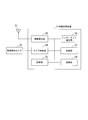
- FIG. 1 is a schematic diagram showing a traffic information processing system 100 according to the first embodiment of the present invention.
- the traffic information processing system 100 is mounted on a vehicle 2 traveling on a road and has an on-vehicle device 1 provided with a uniquely identifiable ID (Identifier), an information collecting device 3 to which a wireless communication antenna 31 and a vehicle detection camera 32 are connected.
- a center server device 5 a GPS (Global Positioning System) satellite 85, and a mobile phone base station device 80.
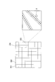
- FIG. 2 is a diagram for explaining a schematic diagram in which a road on which the vehicle 2 travels is divided into mesh shapes.
- the place where the road on which the vehicle 2 travels is divided into a plurality of meshes 201, 202,... 232,.
- the mesh is a square section obtained by dividing the land vertically and horizontally at equal intervals, and a single mesh may include a plurality of roads.
- the mesh 232 includes two roads extending from the upper right to the lower left.
- the shape of the mesh is not limited to a square, but may be a rectangle. Note that the traffic information processing system 100 according to the present embodiment calculates the number of vehicles traveling in a place divided into a plurality of areas in units of meshes.
- the traffic information processing system 100 calculates vehicles in the mesh based on the ratio of the number of vehicles equipped with in-vehicle devices among the vehicles that have entered the sample area that is part of the mesh. In other words, even in the entire mesh including the specimen area, the ratio of the number of vehicles equipped with onboard equipment to the total number of vehicles that entered the specimen area is the number of vehicles equipped with onboard equipment and vehicles not equipped with onboard equipment.
- the total number of vehicles is calculated in units of meshes assuming that they are mixed. That is, in the present embodiment, the section is a mesh, and the specimen area is a concept indicating a check point where the information collection device 3 is installed.
- FIG. 3 is a block diagram showing the internal configuration of the vehicle-mounted device 1.
- the vehicle-mounted device 1 is a detection device that is mounted on the vehicle 2 and detects various information.
- the vehicle-mounted device 1 includes a power supply circuit 10, a built-in battery 11, a wide area communication device 12, a position detection unit 13, a mesh code storage unit 14, a mesh code acquisition unit 15, a mesh code change determination unit 16, A display unit 17, a notification unit 18, a storage unit 19, a control unit 20, and a wireless communication unit 21 are provided.
- the position detection unit 13 includes a GPS receiver 13-1, a GPS complementary sensor unit 13-2, and a dead reckoning processing unit 13-3.
- the power supply circuit 10 has a regulator and a noise protector that stabilize the power supply.
- the power supply circuit 10 receives a 12V or 24V power supply from the vehicle 2 and supplies it to each part of the vehicle-mounted device 1.
- the built-in battery 11 is a backup battery, and supplies power to each unit in order to protect data stored in the vehicle-mounted device 1 when the power supply of the vehicle 2 disappears or is momentarily interrupted.
- the wide area communication device 12 is, for example, a mobile phone terminal, communicates with the base station device 80 via a mobile phone communication network, and transmits / receives data to / from the center server device 5.
- the position detection unit 13 detects the position of the vehicle-mounted device 1 by the GPS receiver 13-1, the GPS complementary sensor unit 13-2, and the dead reckoning processing unit 13-3.
- the GPS receiver 13-1 receives radio waves from the GPS satellite 85, reads time information, and measures latitude and longitude information from the received data.
- the GPS complementary sensor unit 13-2 includes a gyro sensor and an acceleration sensor, and performs a calculation for estimating the position of the vehicle-mounted device 1 from information on the gyro sensor and the acceleration sensor.
- the GPS complementary sensor unit 13-2 may be a component used when, for example, reception sensitivity of radio waves from the GPS satellite 85 is not preferable.
- the dead reckoning processing unit 13-3 includes the latitude and longitude information measured by the GPS receiver 13-1 and the GPS complementary sensor unit 13 according to the accuracy of the information included in the radio wave received by the GPS receiver 13-1. Based on the information on the position of the vehicle-mounted device 1 estimated by -2, an operation for complementing the position of the vehicle-mounted device 1 is performed.
- the mesh code storage unit 14 stores the uniquely identifiable mesh code assigned in advance to each mesh shown in FIG. 2 and information indicating the position of each mesh on the map in association with each other.
- the position of each mesh on the map is represented by, for example, the latitude and longitude of two points on the diagonal line of each mesh.
- the data stored in the mesh code storage unit 14 is updated when the control unit 20 downloads the latest data from the center server device 5 via the wide area communication device 12.
- the mesh code acquisition unit 15 detects a mesh including a position indicated by the latitude and longitude detected by the position detection unit 13 from the mesh code storage unit 14 and acquires a mesh code corresponding to the detected mesh. Further, the mesh code acquisition unit 15 outputs the acquired mesh code in association with information indicating the time read from the radio wave received by the GPS receiver 13-1.
- the mesh code change determination unit 16 determines whether or not the mesh code stored in the storage unit 19 matches the mesh code output by the mesh code acquisition unit 15. When the mesh code change determination unit 16 determines that the two mesh codes do not match, the ID assigned to the vehicle-mounted device 1, the two mesh codes used for the determination, and the time output by the mesh code acquisition unit 15 Is transmitted to the center server device 5 through the wide-area communication device 12 in association with the information indicating. Further, the mesh code change determination unit 16 writes and stores the mesh code output from the mesh code acquisition unit 15 in the storage unit 19 as the latest mesh code when the determination is completed.
- the display unit 17 displays information indicating the state of the vehicle-mounted device 1 and the position on the map.
- the notification unit 18 has a built-in speaker and notifies the driver of the vehicle 2 of information by a buzzer sound or a melody sound.
- storage part 19 memorize
- the control unit 20 performs comprehensive management such as transmission / reception of data of each unit of the vehicle-mounted device 1. For example, when the vehicle-mounted device 1 also serves as a car navigation system, the control unit 20 also performs route guidance processing to a destination that the car navigation system has.
- the wireless communication unit 21 receives the radio wave transmitted by the wireless communication antenna 31 when entering the onboard mounted checkpoint where the information collecting device 3 is installed, and receives the ID given to the onboard device 1 as a response. Send the containing signal.
- FIG. 4 is a block diagram illustrating an internal configuration of the information collection device 3.
- the information collection device 3 includes a wireless communication unit 33, a camera control unit 34, a timer unit 35, an Internet communication unit 36, a control unit 37, and a storage unit 38.
- the wireless communication antenna 31 and the vehicle detection camera 32 are separate devices from the information collection device 3 and are connected to the information collection device 3.
- This information collection device 3 is installed at a predetermined location as an on-board device mounting check point, and is installed, for example, on the shoulder of one road included in a mesh as shown in FIG. In addition, it is preferable that one or more information collecting apparatuses 3 are provided for each mesh.
- the wireless communication antenna 31 and the vehicle detection camera 32 are installed in the vicinity of the information collection device 3 and on an iron pole or the like provided on the shoulder of one lane of the up lane or the down lane or above the road.
- the direction of the lane in which the wireless communication unit 33 transmits a wireless signal through the wireless communication antenna 31 coincides with the direction in which the vehicle detection camera 32 captures an image.
- the wireless communication unit 33 transmits a wireless signal through the wireless communication antenna 31 and receives a signal transmitted by the vehicle-mounted device 1.
- the radio signal transmitted by the radio communication unit 33 through the radio communication antenna 31 is controlled in directivity, and is transmitted toward the up or down lane area that the vehicle detection camera 32 captures,
- the vehicle-mounted device 1 of the vehicle 2 traveling in the other lane is transmitted so as not to react erroneously.
- the wireless communication unit 33 associates the ID of the vehicle-mounted device 1 included in the received signal with information indicating the time acquired from the time measuring unit 35 when the signal is received.
- the data is transmitted to the center server device 5 through the Internet communication unit 36.
- the camera control unit 34 controls the direction of the vehicle detection camera 32 and the shooting conditions, and repeatedly shoots a moving image for a certain period of time. Further, the camera control unit 34 acquires the start time and the end time from the time measuring unit 35 when shooting the moving image, associates the captured moving image file with information indicating the shooting time, and associates the center server device with the Internet communication unit 36. Send to 5.
- the timer 35 has a clock inside and outputs the current time in response to a request.
- the Internet communication unit 36 is connected to the center server device 5 through the Internet and transmits / receives data to / from the center server device 5.
- the control unit 37 performs comprehensive management such as transmission / reception of data of each unit of the information collection device 3.
- the storage unit 38 stores programs and data used by the information collection device 3.
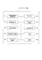
- FIG. 5 is a block diagram showing the internal configuration of the center server device 5.
- the center server device 5 includes an on-vehicle device-equipped vehicle number detection unit 51, a vehicle total number detection unit 52, a vehicle ratio calculation unit 53, a vehicle total number estimation calculation unit 54, an Internet communication unit 55, a mesh code table 56, A mesh code storage unit 57, a traffic information providing unit 58, a storage unit 59, and a control unit 60 are provided.
- the control unit 60 performs comprehensive management such as transmission / reception of data of each unit of the center server device 5.
- the control unit 60 receives information associated with the information indicating the time and the ID of the vehicle-mounted device 1 transmitted by the information collecting device 3 through the Internet communication unit 55, and writes the received information in the storage unit 59 for storage.
- the control unit 60 receives information in which the moving image file captured by the vehicle detection camera 32 transmitted by the information collecting device 3 is associated with information indicating the start and end times of capturing of the moving image. The information thus written is stored in the storage unit 59.
- the control unit 60 may receive a moving image file periodically transmitted from the vehicle detection camera 32 and acquire a captured image, and requests transmission of the moving image file.
- the control unit 60 receives information in which the vehicle-mounted device ID transmitted from the vehicle-mounted device 1 through the base station device 80 is associated with the two old and new mesh codes, and writes and stores the information in the mesh code table 56.
- the storage unit 59 stores programs and data used in the center server device 5.
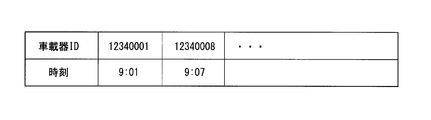
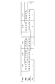
- the storage unit 59 includes a table having items of information indicating the ID and time of the vehicle-mounted device shown in FIG. 6A, and stores information in which the ID of the vehicle-mounted device 1 and the information indicating the time written by the control unit 60 are associated with each other.
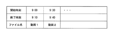
- the storage unit 59 stores the moving image file written by the control unit 60, and is a table for referring to the moving image file.
- the items of moving image shooting start time and end time and moving image file name shown in FIG. 6B Having a table. With this table, the storage unit 59 stores information indicating the start and end times of moving image shooting written by the control unit 60 and the corresponding moving image file name.
- the mesh code table 56 stores a plurality of tables for each mesh code.
- the table corresponding to the mesh 201 is the table 56-201, and the table corresponding to the mesh 202 is stored in order as the table 56-202.
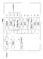
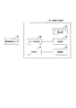
- Each table has, for example, an on-vehicle device ID, an entry time, an exit time, and a presence detection item as shown in a table 56-232 corresponding to the mesh 232 in FIG. 7, and the ID of the on-vehicle device that has entered the mesh.
- Information indicating the entry time and exit time of the mesh 232 and the presence detection is stored for each.
- the mesh code storage unit 57 stores the same data as the data stored in the mesh code storage unit 14 of the vehicle-mounted device 1.
- the mesh code storage unit 57 stores the latest data, and the vehicle-mounted device 1 downloads the data stored in the mesh code storage unit 57 and updates the data in the mesh code storage unit 14 as described above. To do.
- the vehicle-mounted device number detection unit 51 determines how many IDs of the vehicle-mounted device during the time arbitrarily determined from the information in which the ID of the vehicle-mounted device and the time shown in FIG. Is stored, and the detected number is output as the number of vehicles 2 equipped with the vehicle-mounted device 1.
- the vehicle total number detection unit 52 reads out the moving image file stored in the storage unit 59 with reference to the table shown in FIG. 6B and analyzes the read moving image file to detect the number of vehicles photographed in the moving image. .
- the vehicle ratio calculation unit 53 is equipped with the vehicle-mounted device 1 based on the number of vehicles 2 equipped with the vehicle-mounted device 1 output from the vehicle-mounted device number detection unit 51 and the number of vehicles detected by the vehicle total number detection unit 52. The ratio of the number of all vehicles to the number of vehicles to be calculated is calculated.
- the vehicle total number estimation calculation unit 54 detects the number of vehicles 2 entering each mesh at a time arbitrarily determined from the mesh code table 56, and at the time based on the ratio calculated by the vehicle ratio calculation unit 53. A calculation is performed to estimate the number of all vehicles present in each mesh.
- the Internet communication unit 55 is connected to the base station device 80 via the Internet network, and transmits and receives data to and from the vehicle-mounted device 1.
- the traffic information providing unit 58 transmits, for example, information indicating the traffic state calculated by the total vehicle number calculating unit 54 to the vehicle-mounted device 1 through the Internet communication unit 55.
- the information collecting device 3 operates for a certain time at certain intervals. For example, an operation such as starting at 0 minutes every hour and 30 minutes, operating for 10 minutes and stopping is performed.
- the control of the start and stop is performed by the control unit 37 giving a start instruction and a stop instruction to each functional unit using time information acquired from the time measuring unit 35.
- the operation by the wireless communication unit 33 and the operation by the camera control unit 34 are performed in parallel.
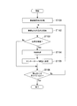
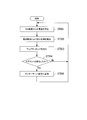
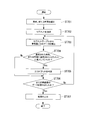
- the operation of the wireless communication unit 33 shown in FIG. 8 will be described.
- Step ST101 The wireless communication unit 33 is activated in response to an activation instruction from the control unit 37.
- the wireless communication unit 33 transmits a wireless signal through the wireless communication antenna 31.
- the wireless communication part 33 determines whether the signal transmitted from the onboard equipment 1 was received in response to the transmitted radio signal.
- Step ST104 When determining that the signal is received from the vehicle-mounted device 1, the wireless communication unit 33 reads the ID of the vehicle-mounted device 1 included in the received signal and acquires the time from the time measuring unit 35. (Step ST105) Then, the wireless communication unit 33 associates the ID of the vehicle-mounted device 1 with the time and transmits it to the center server device 5 through the Internet communication unit 36.
- the control unit 60 of the center server device 5 receives the information in which the ID of the vehicle-mounted device 1 is associated with the time from the information collection device 3 through the Internet communication unit 55, the control unit 60 stores the information in the table shown in FIG. Write and store.
- Step ST106 On the other hand, when it determines with the radio
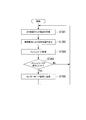
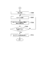
- Step ST201 First, the camera control unit 34 is activated in response to an activation instruction from the control unit 37.
- Step ST202 Next, the camera control unit 34 acquires the time from the time measuring unit 35 and temporarily stores it in the storage unit 38 as the start time.
- Step ST203 Then, the camera control unit 34 starts shooting a moving image through the vehicle detection camera 32.
- Step ST204 Thereafter, for example, when 10 minutes have elapsed since the start of shooting, the camera control unit 34 ends the shooting, acquires the time from the time measuring unit 35, and sets it as the end time.
- Step ST205 the camera control unit 34 reads the start time from the storage unit 38, associates the moving image file of the shot video with the start time and the end time, and transmits them to the center server device 5 through the Internet communication unit 36, thereby terminating the operation. To do.
- the control unit 60 of the center server device 5 When receiving the information through the Internet communication unit 55, the control unit 60 of the center server device 5 reads a moving image file from the information and writes it in the storage unit 59. Further, the control unit 60 of the center server device 5 reads information indicating the start time and end time from the information received through the Internet communication unit 55, and corresponds the start time, end time, and moving image file name to the table shown in FIG. 6B. Then write.
- the information collection device 3 By the operation of the information collection device 3 described above, all the vehicles passing through the onboard equipment checkpoint are photographed by the vehicle detection camera 32, and the number of vehicles 2 equipped with the onboard equipment 1 passing through the onboard equipment checkpoint. It is possible to collect the information necessary for counting.
- Step ST301 operation
- movement of the onboard equipment 1 is demonstrated, referring the flowchart of FIG. (Step ST301)
- the vehicle 2 travels on a road from the mesh 231 to the mesh 232 and enters the mesh 232.
- the GPS receiver 13-1 of the vehicle-mounted device 1 of the vehicle 2 receives radio waves from the GPS satellite 85 at a constant cycle.
- the GPS receiver 13-1 measures latitude and longitude from information included in the received radio wave, information on latitude and longitude, information on time included in the received radio wave, and information included in the received radio wave. Outputs information indicating the reliability of.
- the GPS receiver 13-1 has information indicating that the position of the vehicle-mounted device 1-1 is the point P1 (latitude ⁇ 1 , longitude ⁇ 1 ) and the time at which the position is detected is “9. : 01 ”and information indicating reliability“ high ”are output in association with each other.
- Step ST302 the GPS complementary sensor unit 13-2 outputs the time “output” from the GPS receiver 13-1 based on the rotation direction of the vehicle 2 obtained from the gyro sensor and the speed information of the vehicle 2 obtained from the acceleration sensor. 9:01 "is performed to estimate the position where the vehicle-mounted device 1 exists.
- the GPS complementary sensor unit 13-2 obtains information indicating the point P2 (latitude ⁇ 2 , longitude ⁇ 2 ) as the position of the vehicle-mounted device 1 as a calculation result.
- the dead reckoning processing unit 13-3 uses the information of the two positions obtained from the GPS receiver 13-1 and the GPS complementary sensor unit 13-2, and uses the method shown in FIG. Is calculated.
- the position of the vehicle-mounted device 1 estimated by calculation by the GPS complementary sensor unit 13-2 is a position indicated by a point P2 (latitude ⁇ 2 , longitude ⁇ 2 ), and the GPS receiver 13-1 Assume that the position based on the output latitude and longitude information is the position indicated by the point P1 (latitude ⁇ 1 , longitude ⁇ 1 ). In this case, the dead reckoning processing unit 13-3 sets the position of the point P3 (latitude ⁇ 3 , longitude ⁇ 3 ) by the weighted average calculation using the reliability of the information output from the GPS receiver 13-1 as a weight. Calculated as the position of 1.
- the dead reckoning processing unit 13-3 includes the calculated position information (that is, information indicating the point P3 (latitude ⁇ 3 , longitude ⁇ 3 )) and the time information “9: output from the GPS receiver 13-1. 01 ”is output in correspondence to the mesh code acquisition unit 15. It should be noted that the position that becomes the starting point when the GPS complementary sensor unit 13-2 performs the calculation for estimating the position is the position indicated by the point P3 (latitude ⁇ 3 , longitude ⁇ 3 ).
- the mesh code acquisition unit 15 receives the point P3 (latitude ⁇ 3 , longitude ⁇ 3 ) and time information “9:01” as position information from the dead reckoning processing unit 13-3, and receives the mesh information storage unit 14 reads out a set of latitude and longitude information indicating the position of each mesh, detects a mesh containing the position received from dead reckoning processing section 13-3, and mesh code corresponding to the detected mesh To get.
- the mesh code acquisition unit 15 acquires the mesh code
- the mesh code acquisition unit 15 outputs information indicating the acquired mesh code and time to the mesh code change determination unit 16.
- the mesh code change determination unit 16 reads the previous mesh code acquired in the storage unit 19, and does the read mesh code match the mesh code output by the mesh code acquisition unit 15? Determine whether or not.
- Step ST305 When the mesh code change determination unit 16 determines that the mesh codes do not match, that is, the mesh code has changed, the ID assigned to the vehicle-mounted device 1 and the latest mesh code output by the mesh code acquisition unit 15 Then, the mesh code read from the storage unit 19 and the information indicating the time are associated with each other and transmitted to the center server device 5 through the wide area communication device 12. Then, the mesh code change determination unit 16 writes and stores the latest mesh code in the storage unit 19, and repeats the processing from step ST301. On the other hand, when the mesh code change determination unit 16 determines that the mesh codes match, that is, the mesh code has not changed, the mesh code change determination unit 16 writes the latest mesh code output by the mesh code acquisition unit 15 in the storage unit 19 and stores it. The process from step ST301 is repeated.
- the control unit 60 of the center server device 5 receives the information indicating the ID of the vehicle-mounted device 1, the two old and new mesh codes, and the time from the vehicle-mounted device 1 through the Internet communication unit 55, the old mesh code is read and the old mesh code is converted into the old mesh code.
- a corresponding table is detected from the mesh code table 56.
- the old mesh code is 231, the table 56-231 is detected, the received time is written in the exit time column of the corresponding onboard device ID in the table 56-231, and the exit is entered in the presence detection column. Record “-” to indicate the status.
- the control unit 60 reads a new mesh code from the received information, and detects a table corresponding to the read new mesh code from the mesh code table 56.
- the table 56-232 is detected, and the newly received OBE ID line is added to the table 56-232, and the entry time entry of the added line is received. Is recorded, and “ ⁇ ” indicating the existing state is recorded in the presence detection column.
- the above processing is performed by the vehicle-mounted device 1 mounted on the plurality of vehicles 2, and each corresponding table of the mesh code table 56 of the center server device 5 each time the plurality of vehicle-mounted devices 1 enter another mesh.
- the entry time, exit time, and presence detection are updated and information is accumulated.
- the mesh code acquisition unit 15 acquires a mesh code for the first time, the previous mesh code is not stored in the storage unit 19.
- the mesh code change determination unit 16 determines that the mesh code has changed even when a new mesh code is acquired from a state in which there is no previous mesh code.
- the center server device 5 can collect information about when the vehicle 2 on which the vehicle-mounted device 1 is mounted enters and exits which mesh.
- the vehicle-mounted device number detection unit 51 of the center server device 5 selects a target time for calculating the vehicle-mounted device mounting rate.
- the operator of the center server device 5 may select this time arbitrarily. However, in this example, the shooting interval of the moving image is set to 0 minutes and 30 minutes per hour, and 10 minutes is taken. Select one of the times. Here, it is assumed that 9:00 to 9:10 are selected.
- the vehicle-mounted device number detection unit 51 mounts the vehicle-mounted device by counting the number of data received from the vehicle-mounted device 1 between 9:00 and 9:10 from the table shown in FIG. 6A of the storage unit 59.
- the vehicle total number detection unit 52 refers to the table shown in FIG. 6B of the storage unit 59 and reads the moving image 1 that is a moving image file shot from 9:00 to 9:10 from the storage unit 59.
- the vehicle total number detection unit 52 calculates the number of vehicles that have traveled the onboard mounted checkpoint from 9:00 to 9:10 by performing image analysis on the read video 1 file.
- Step ST404 the vehicle ratio calculation unit 53 calculates the number of vehicles equipped with the vehicle-mounted device from the number of vehicles equipped with the vehicle-mounted device calculated by the vehicle-mounted device number detection unit 51 and the number of vehicles calculated by the vehicle total number detection unit 52. The ratio of the number of all vehicles to the number is calculated.
- Step ST405 the vehicle total number estimation calculation unit 54 selects a time at which the total number of vehicles in the mesh is to be confirmed, and the number of vehicles 2 that have entered at that time is shown in each table 56-201, 56-202,. Detect from. More specifically, the vehicle total number estimation calculation unit 54 refers to the mesh code table 56 and counts the number of vehicle-mounted device IDs that have entered but have not exited at the selected time.
- Step ST406 the vehicle total number estimation calculation unit 54 uses the detected number of vehicles of each mesh and the ratio calculated by the vehicle ratio calculation unit 53 to mount the vehicle equipped with the on-vehicle device of each mesh and the on-vehicle device. Calculation is performed to estimate the number of all vehicles that are the total number of vehicles that are not. For example, when the calculation by the vehicle ratio calculation unit 53 is a calculation to divide the number of vehicles equipped with the vehicle-mounted device by the total number of vehicles, the vehicle total number calculation calculation unit 54 calculates the vehicle of each mesh calculated in step ST405. A value for estimating the number of all vehicles in each mesh can be calculated by dividing the number by the value calculated by the vehicle ratio calculation unit 53.
- the vehicle total number estimation calculation unit 54 outputs the estimated value of the number of all vehicles to the traffic information providing unit 58.
- the traffic information providing unit 58 may send this value as it is to the on-vehicle device 1 as information indicating the degree of congestion and provide the mesh that is congested based on this value in an easy-to-understand manner. Such image information may be provided.
- the exact congestion degree can be calculated
- the degree of congestion is obtained based on the number of all vehicles in the mesh.
- the present invention is not limited to this. For example, by analyzing the change in the number of all vehicles in the mesh in time series, it is possible to grasp the flow and movement of people. Information that grasps the flow and movement of people is effective information in marketing strategies and the like.
- the number of vehicles equipped with the vehicle-mounted device 1 in a limited range that is, a more limited vehicle-mounted device-mounted checkpoint of one mesh by one information collecting device 3. And collect information on the number of all passing vehicles.
- the center server apparatus 5 it has the structure which uses it for the calculation which estimates the number of all the vehicles of each mesh, using the information collected by the information collection apparatus 3. FIG. Therefore, it is not necessary to install a device for detecting these numbers in all the meshes, and the installation cost of the system can be suppressed.
- the on-board device mounting checkpoint in which the information collecting device 3 is installed is set to one location.
- the ratio of all vehicles to the vehicle on which the on-board device is mounted varies depending on the region.
- a plurality of points 3-1 to 3-4 may be provided.
- the vehicle ratio calculation unit 53 detects the total number of vehicles mounted with the vehicle-mounted device at each point calculated by the vehicle-mounted device vehicle number detection unit 51 and the total number of vehicles. The total value of the number of all vehicles at each point calculated by the unit 52 may be calculated, and the ratio may be calculated based on these total values.
- the average value of the number of vehicles carrying the vehicle-mounted device at each point and the average value of the number of all vehicles at each point may be calculated, and the ratio may be calculated from these values. If there is variation at each point, the ratio may be calculated in consideration of weighting according to the distribution.
- the time is selected in step ST405 of FIG. 12, but the number of all vehicles of each mesh at the time when the processing of FIG. 12 is performed is estimated. You may make it do.
- the number of vehicle-mounted device IDs with “ ⁇ ” in the presence detection item of each table of the mesh code table 56 may be counted. This makes it possible to calculate the number of vehicles 2 that have entered each mesh at that time.
- FIG. 14 is a schematic diagram showing a traffic information processing system 300.
- the traffic information processing system 300 includes an in-vehicle device 7 that is mounted on a vehicle 8 that travels on a road and is given a uniquely identifiable ID, an information collection device 3a to which a vehicle detection camera 32 is connected, a center server device 9, , A GPS satellite 85 and a mobile phone base station device 80.
- the road on which the vehicle 8 travels is divided in advance into a plurality of sections called segments, and uniquely identifiable IDs are assigned to the segments such as segments 1, 2, 3,. Has been granted.
- the onboard mounted checkpoint where the information collecting device 3a is installed is one of the up lane and the down lane of any segment, and the direction in which the vehicle detection camera 32 captures is the target It becomes one lane targeted for the segment.
- the vehicle detection camera 32 is set so that the entrance of the upstream lane of the segment 4 is an on-board device check point and the entrance of the upstream lane of the segment 4 is photographed.
- the traffic information processing system 300 calculates the number of vehicles traveling on a road divided into a plurality of areas in units of segments.
- the traffic information processing system 100 calculates the number of vehicles in the mesh based on the ratio of the number of vehicles equipped with in-vehicle devices out of vehicles that have entered a sample area that is a part of a plurality of segments. That is, in this embodiment, a zone is a region composed of a plurality of segments, and a sample area is a concept indicating a segment in which the information collection device 3 is installed. In the present embodiment, the sample area is described using an example in which one segment is used. However, the present invention is not limited to this, and an area including a plurality of segments may be used.
- FIG. 15 is a block diagram showing an internal configuration of the vehicle-mounted device 7.
- the map matching processing unit 70 matches the segment position information stored in the road map data storage unit 71 with the in-vehicle device 1 position information detected by the position detection unit 13.
- the map matching processing unit 70 is an example of a configuration unit that functions as a segment detection unit that detects a segment corresponding to a position detected by the position detection unit 13 from a plurality of segments that are sections obtained by dividing a road.
- the segment change determination unit 72 determines whether or not the vehicle-mounted device 7 has entered a new segment based on the detection processing result of the map matching processing unit 70. In addition, for example, when the in-vehicle device 7 determines that the vehicle-mounted device 7 has entered a new segment, the segment change determining unit 72 associates the newly entered segment ID, time information, and the vehicle-mounted device ID, respectively. The information is transmitted to the center server device 9 through the wide area communication device 12.
- the storage unit 73 stores programs and data used in the vehicle-mounted device 7. For example, as shown in FIG. 16, the storage unit 73 is associated with the time information included in the radio wave from the GPS satellite 85, the latitude and longitude information detected by the position detection unit 13, and the map matching process A table storing segment IDs obtained as a result of the matching of the unit 70; In the table, a segment ID not recorded (item with “ ⁇ ”) indicates that the corresponding segment is not detected by the map matching processing unit 70.
- the control unit 74 performs comprehensive management such as transmission / reception of data of each unit of the vehicle-mounted device 7. For example, when the vehicle-mounted device 7 also serves as a car navigation system, the control unit 74 uses the route guidance processing to the destination of the car navigation system and information indicating the degree of congestion received from the center server device 9. Based on this, processing for selecting the optimum route to the destination is also performed.
- the road map data storage unit 71 stores road map data in the segment format described above, and includes information on the latitude and longitude of the start and end points of each segment, and information indicating the connection relationship of each segment. ing. Note that not all roads are shown divided into segments, and roads for which the degree of congestion is to be detected are stored in segment format.
- the data stored in the road map data storage unit 71 is updated when the control unit 74 downloads the latest data from the center server device 9 via the wide area communication device 12.
- FIG. 17 is a block diagram showing an internal configuration of the information collection device 3a.
- the information collection device 3a has the same configuration as the information collection device 3 except that the wireless communication antenna 31 and the wireless communication unit 33 are excluded from the information collection device 3 of the first embodiment. Description is omitted.
- FIG. 18 is a block diagram showing an internal configuration of the center server device 9.
- the control unit 92 performs comprehensive management such as transmission / reception of data of each unit of the center server device 9.
- the control unit 92 receives the moving image file photographed by the vehicle detection camera 32 transmitted by the information collecting device 3 a and the information on the start and end times of the photographing of the moving image, and writes the received information in the storage unit 93.
- the control unit 92 receives the ID of the newly entered segment transmitted by the vehicle-mounted device 7 through the base station device 80, information about the time, and the vehicle-mounted device ID, and writes and stores them in the segment table 90.
- the storage unit 93 stores programs and data used in the center server device 5.
- the storage unit 93 stores the moving image file written by the control unit 92, and also refers to the moving image file, in the same manner as in the first embodiment, for the start time and end time of moving image shooting and the moving image file name shown in FIG. 6B. Store table with entries.
- the road map data storage unit 91 stores the same data as the data stored in the road map data storage unit 71 of the vehicle-mounted device 7 described above.
- the road map data storage unit 91 stores the latest data.
- the vehicle-mounted device 7 downloads the data stored in the road map data storage unit 91 and the data in the road map data storage unit 71. Update.
- the segment table 90 is, for example, a table having the format shown in FIG. 19, and stores data received by the Internet communication unit 55 from the vehicle-mounted device 7.
- the segment table 90 first has an on-vehicle device ID item, and has a plurality of items each of which includes a time and Seg (segment) item.
- the movement direction determination unit 94 determines the movement direction of the vehicle 8 based on the information stored in the segment table 90.
- the vehicle-mounted device number detection unit 51a detects the number of vehicles 8 equipped with the vehicle-mounted device 7 based on the data stored in the segment table 90.
- the vehicle total number estimation calculation unit 54a detects the number of vehicles 8 entering each segment at a time arbitrarily determined from the segment table 90, and at each time based on the ratio calculated by the vehicle ratio calculation unit 53. A calculation is performed to estimate the number of all vehicles present in the segment.
- the traffic information providing unit 58a transmits, for example, information indicating the traffic state calculated by the vehicle total number estimation calculation unit 54a to the vehicle-mounted device 7 through the Internet communication unit 55.
- Step ST501 operation
- movement of the onboard equipment 7 is demonstrated, referring the flowchart of FIG. (Step ST501)
- a certain vehicle 8 in FIG. 14 enters segment 1 from a state where a segment is not allocated on the road leading to segment 1.
- the GPS receiver 13-1 of the vehicle-mounted device 7 of the vehicle 8 receives radio waves from the GPS satellite 85 at a constant cycle.
- the GPS receiver 13-1 measures latitude and longitude from information included in the received radio wave, and measures the latitude and longitude information, the time information included in the received radio wave, and the received radio wave. Outputs information indicating the reliability of the included information.
- the GPS receiver 13-1 has information indicating that the position of the vehicle-mounted device 1-1 is the point P1 (latitude ⁇ 1 , longitude ⁇ 1 ), and the time when the position is detected is “8. : 26 ”and information indicating the reliability“ high ”are output in association with each other.
- Step ST502 the GPS complementary sensor unit 13-2 outputs the time “output” from the GPS receiver 13-1 based on the rotation direction of the vehicle 8 obtained from the gyro sensor and the speed information of the vehicle 8 obtained from the acceleration sensor. 8:26 ", a calculation for estimating the position where the vehicle-mounted device 7 exists is performed.
- the GPS complementary sensor unit 13-2 obtains information indicating the point P2 (latitude ⁇ 2 , longitude ⁇ 2 ) as a position of the vehicle-mounted device 1-1 as a calculation result.
- the dead reckoning processing unit 13-3 uses the information of the two positions obtained from the GPS receiver 13-1 and the GPS complementary sensor unit 13-2, and uses the method shown in FIG.
- the dead reckoning processing unit 13-3 calculates the calculated position information (that is, information indicating the point P 3 (latitude ⁇ 3 , longitude ⁇ 3 )) and the time information “8” output from the GPS receiver 13-1. : 26 ”is written and stored in the table of the storage unit 73 shown in FIG. 16 and is output to the map matching processing unit 70.
- the data in FIG. 16 is written with data at 8:26.
- the map matching processing unit 70 receives the point P3 (latitude ⁇ 3 , longitude ⁇ 3 ) and time information “8:26” as position information from the dead reckoning processing unit 13-3, and stores the information “8:26” in the storage unit 73.
- the past position information of the vehicle-mounted device 7 stored in the table and the time information associated with the position information are read out and arranged in time series to obtain the trajectory of the vehicle 8, that is, the track of the on-vehicle device 7. .
- the locus of the vehicle-mounted device 7 is a locus I as indicated by a dotted line in FIG.
- the map matching processing unit 70 uses the data stored in the road map data storage unit 71 as three candidate routes C1, C2, and C3 as candidate routes corresponding to the obtained trajectory I. Extract. Then, the map matching processing unit 70 determines the route candidate with the smallest error amount from the area (shaded region in FIG. 21) of the region surrounded by the obtained trajectory I and each of the route candidates C1, C2, and C3. Determine. In the present embodiment, the map matching processing unit 70 sets the path candidate C2 having the smallest area (shaded area in FIG. 21) surrounded by the path I and the path candidate as the path I of the vehicle-mounted device 7. It is determined as the corresponding route.
- the map matching process part 70 matches the path
- the map matching processing unit 70 records the segment ID of the detected segment in association with the position and time information in the storage unit 73 based on the time information corresponding to the segment ID, and the segment change determination unit 72. Output to.
- the point P3 latitude ⁇ 3 , longitude ⁇ 3
- the map matching processing unit 70 determines that the vehicle-mounted device 1 has entered the segment 1 at time “8:26”.
- the map matching processing unit 14 writes “1” in the Seg (segment) item corresponding to the time “8:26”. If the corresponding segment ID cannot be detected, the map matching processing unit 70 writes “ ⁇ ” in the Seg item of the table of the storage unit 73 as described above.
- Step ST504 the segment change determination unit 72 receives the segment ID “1” and the time information “8:26” from the map matching processing unit 70, and receives the segment ID information of the previous time from the table in the storage unit 73. To determine whether the segment ID has changed.
- the Seg item corresponding to the previous time (“8:25” in FIG. 16) is displayed. “-” Indicating that there is no corresponding segment ID is recorded.
- the segment change determination unit 72 records a value different from the segment ID at the target time in the segment ID for the previous time when a new segment ID is detected from a state in which no segment ID is recorded. In this case, it is determined that the segment ID has changed.
- the segment change determination unit 72 determines that there is no change, and returns to the process of step ST501.
- Step ST505 If the segment change determination unit 72 determines that the segment ID has changed, the segment ID “1” received from the map matching processing unit 70 and the time information “8:26 corresponding to the segment ID“ 1 ”are displayed. ”And the vehicle-mounted device ID“ 12340001 ”are transmitted to the center server device 9 via the wide area communication device 12.
- the control unit 92 of the center server device 9 receives data from the vehicle-mounted device 7 through the Internet communication unit 55, the control unit 92 writes the received data in the segment table 90 as shown in FIG.
- the vehicle-mounted device 7 corresponds to the vehicle-mounted device ID “12340001”, “8:26” is written in the item of time 1 in the row of the vehicle-mounted device ID “12340001”, and the segment 1 is shown in the corresponding Seg item. “1” is written.
- the vehicle-mounted device 7 writes data in the table of the storage unit 73 every time the position is measured.
- the segment change determination unit 72 determines that the segment ID has changed, the vehicle-mounted device 7 transmits data to the center server device 9 and the data is written in the segment table 90 of the center server device 9.
- the segment change determination unit 72 determines in step ST504 that the segment has changed, the segment ID received from the map matching processing unit 70, the time information corresponding to the segment ID, the vehicle-mounted device ID “ 12340001 ”is transmitted to the center server device 9.
- the center server device 9 writes the received information in the segment table 90. More specifically, the center server device 3 records data as shown in the row of the vehicle-mounted device ID “12340001” in FIG. 19 in the segment table 90.
- step ST503 when the vehicle 8 leaves the segment 6, the map matching processing unit 70 cannot detect the corresponding segment ID in the process of step ST503, so the time in the storage unit 73 of the vehicle-mounted device 7 is "9: As shown in the Seg item corresponding to the item “23”, “ ⁇ ” is written assuming that there is no corresponding segment ID. Then, in step ST504, the segment change determination unit 72 determines that the segment has changed even when the segment ID is changed to a state where there is no corresponding segment ID, and transmits data to the center server device 9. The center server device 9 writes in the segment table 90 a state (“-”) that does not have a corresponding segment ID as shown in the Seg item at time 5 in FIG.
- the on-vehicle device 7 includes the on-vehicle device in the segment ID in which the on-vehicle device 7 exists and the segment indicated by the segment ID. 7 is transmitted to the center server device 9 in association with the time when 7 starts to exist. Thereby, compared with the case where all the time and position information as shown in FIG. 16 are transmitted to the center server apparatus 9, the frequency
- Step ST601 the vehicle-mounted device number detection unit 51a of the center server device 5 selects a target time for calculating the vehicle-mounted device mounting rate. As in the first embodiment, in this example, it is assumed that 9:00 to 9:10 is selected according to the shooting time of the moving image.
- Step ST602 The vehicle-mounted device number detection unit 51a selects the on-vehicle device mounted checkpoint segment in which the information collecting device 3a is installed. Here, segment 4 is selected as shown in FIG.
- Step ST603 The vehicle-mounted device number detection unit 51a calls a subroutine shown in FIG. 24 in order to detect the number of vehicles 8 that have entered the upstream lane of segment 4 between 9:00 and 9:10.
- FIG. 25 is a diagram showing the data stored in the segment table 90 shown in FIG. 19 in a visually easy-to-understand manner.
- the vehicle-mounted device 1 with the vehicle-mounted device ID “1234341” enters the segment 1 at 8:26, enters the segment 2 at 8:34, enters the segment 4 at 8:46, and 9: 06 indicates that the segment 6 has been entered, and 9:23 that the segment 6 has exited.
- Step ST701 In order to detect the number of vehicles 8 existing in any one segment from the segment table 90 during a predetermined time or a predetermined time, the vehicle-mounted device number detection unit 51a includes a target time, Or make a time selection. Here, since the time from 9:00 to 9:10 has already been selected in the process of step ST601 of the main routine, the same time from 9:00 to 9:10 is selected. (Step ST702) Next, the vehicle-mounted device number detection unit 51a selects a target segment. This segment has already been selected in step ST602 of the main routine, and segment 4 is selected. (Step ST703) And the vehicle equipment mounting vehicle number detection part 51a reads the segment ID matched with the selected time slot
- zone (9:00 to 9:10) zone
- Step ST704 And the onboard equipment vehicle number detection part 51a determines whether the onboard equipment 7 was approaching into the selected segment 4 at the selected time based on the read information.
- the vehicle-mounted device 7 with the vehicle-mounted device ID “12340001” that is read first the vehicle enters the segment 4 at 8:46 and leaves the segment 4 at 9:06. For this reason, the vehicle-mounted device number detection unit 51 a determines that the vehicle-mounted device 7 with the vehicle-mounted device ID “12340001” has entered the segment 4.
- Step ST705 When the on-vehicle device number detecting unit 51a determines that the target on-vehicle device 7 has entered the segment 4 from 9:00 to 9:10, the vehicle detection camera 32 enters the ascending lane that is the subject of imaging. In order to calculate the number of vehicles 8 that are present, the movement direction determination unit 94 determines the movement direction. The vehicle-mounted device number detection unit 51a outputs the vehicle-mounted device ID “12340001” of the target vehicle-mounted device 7 and the segment ID “4” being selected to the movement direction determining unit 94. Then, the movement direction determination unit 94 reads data corresponding to the vehicle-mounted device ID “12340001” output from the vehicle-mounted device number detection unit 51 a from the segment table 90.
- Step ST706 On the other hand, if the onboard equipment mounted vehicle number detection unit 51a determines that the target onboard equipment 7 has not entered the segment 4 from 9:00 to 9:10, the process proceeds to step ST706.
- This onboard equipment number-of-vehicles detection part 51a determines whether the data of all the onboard equipments 7 were read. And the onboard equipment vehicle number detection part 51a repeats the process from step ST703, when the data of all the onboard equipments 7 are not read.
- Step ST707 On the other hand, when the data of all the vehicle-mounted devices 7 are read, the vehicle-mounted device number detection unit 51 a calculates the number of vehicles 8 that have entered the upstream lane of the segment 4 and outputs the calculated number to the vehicle ratio calculation unit 53.
- the vehicle unit-equipped vehicle number detection unit 51a outputs “3” as the number of vehicles entering the upstream lane.
- the road map data storage unit 91 stores the fact that the road map data storage unit 91 has entered the upstream lane when entering the segment 1 from the state where the segment ID does not exist. The direction can be determined.
- Step ST604 The process of step ST604 by the vehicle total number detection unit 52 is the same as the process of step ST403 of FIG. 12 described above, and here the vehicle that has read the moving image file from 9:00 to 9:10 and traveled the onboard mounted checkpoint Calculate the number of units.
- Step ST605 the process of step ST605 by the vehicle ratio calculation part 53 is also the same as the process by step ST404 of FIG. 12 mentioned above, and, as a result, the vehicle ratio calculation part 53 is calculated by the vehicle-mounted device number detection unit 51a.
- the ratio of the number of all vehicles to the number of vehicles equipped with the vehicle-mounted device is calculated from the number of vehicles equipped with the device and the number of vehicles calculated by the vehicle total number detection unit 52.
- Step ST606 Proceeding to FIG. 23, the vehicle total number estimation calculation unit 54 a selects a time at which the total number of vehicles in the segment is to be confirmed.
- Step ST607 The vehicle total number estimation calculation unit 54a selects the segments 1 in order from the segment table 90 in order to detect the number of vehicles 8 entering each segment at that time.
- Step ST608 Next, the vehicle total number estimation calculation unit 54a selects a time and a segment and calls a subroutine shown in FIG.
- the vehicle total number estimation calculation unit 54a can obtain the number of vehicles 8 that have entered the target segment at the target time. Note that when the vehicle total number estimation calculation unit 54a calls the subroutine of FIG. 24, information on whether the vehicle has entered the up lane or the down lane is not essential, so the process of step ST705 is performed. It may not be performed.
- Step ST609 The vehicle total number estimation calculation unit 54a determines whether or not all segments have been selected. This vehicle total number estimation calculation part 54a repeats the process from step ST607, when not selecting all the segments. Note that all segments are all segments included in an area in which segment 4 is determined to be a sample area. In this embodiment, this area is segments 1 to 6 and the specimen area is segment 4. (Step ST610) On the other hand, when all the segments have been selected, the vehicle total number estimation calculation unit 54a uses the calculated number of vehicles of each segment and the ratio calculated by the vehicle ratio calculation unit 53 to install the vehicle-mounted device of each segment. A calculation is performed to estimate the total number of vehicles equipped with the vehicle and vehicles not equipped with the vehicle-mounted device.
- the number of vehicles in each segment is a value calculated by the vehicle ratio calculation unit 53. By dividing, a value for estimating the number of all vehicles in each segment can be calculated.
- the vehicle total number estimation calculation unit 54a outputs the estimated value of the number of all vehicles to the traffic information providing unit 58a, and the traffic information providing unit 58a transmits the value as it is to the in-vehicle device 7 as information indicating the degree of congestion. Based on this value, image information that provides a clear illustration of the crowded segment may be provided.
- the number of all vehicles is estimated in units of meshes having a certain area, whereas in the configuration of the second embodiment, all roads are divided into segment units. The number of vehicles is estimated. For this reason, according to the structure of 2nd Embodiment, it becomes possible to obtain
- the number of vehicles equipped with the vehicle-mounted device 7 in a limited range of one segment and all the vehicles that pass through the same information collecting device 3a Collect information on the number of cars.
- the center server device 9 is configured to use the information collected by the information collecting device 3a and use it for calculation to estimate the number of all vehicles in other segments. Therefore, it is not necessary to install a device for detecting these numbers in all segments, and the installation cost of the system can be suppressed.
- the on-board device mounting checkpoint for installing the information collecting device 3a is set to one place as in the first embodiment, but the ratio of all vehicles to the vehicle on which the onboard device is mounted is as follows.
- the information collection device 3a may be installed in a plurality of segments.
- the up lane of the segment 4 is targeted.
- two vehicle detection cameras 32 may be installed to obtain the ratio including the down lane of the segment 4 as a target.
- the processing in step Sd103 in the center server device 9 detects the vehicle 8 on which the vehicle-mounted devices 7 in the up lane and the down lane are mounted.
- a relatively short distance segment is set, and both the up lane and the down lane are photographed by one vehicle detection camera 32, and the number of vehicles traveling in each of the up lane and the down lane is determined from the photographed images.
- the ratio may be obtained by detection.
- the value of the number of vehicles equipped with the vehicle-mounted device at each point calculated by the vehicle-mounted device number detection unit 51a and the value of the number of all vehicles at each point calculated by the vehicle total number detection unit 52 are obtained.
- the respective total values may be calculated as in the first embodiment, and the ratio may be calculated based on these total values.
- the average value of the number of vehicles carrying onboard equipment and the average value of the number of all vehicles may be calculated, and a ratio may be calculated by these values. If there is variation at each point, the ratio may be calculated in consideration of weighting according to the distribution.
- the number of vehicles 8 carrying the onboard equipment 7 which passes the onboard equipment mounting checkpoint is calculated using the information memorize
- FIG. Thus, the costs of the wireless communication antenna 31 and the wireless communication unit 33 can be reduced compared to the first embodiment.
- the present invention is not limited to the embodiment.
- the information collecting device 3a is provided with a wireless communication antenna and a wireless communication unit, and passes through the onboard mounted checkpoint according to the same procedure as in the first embodiment.
- the number of vehicles 8 equipped with the vehicle-mounted device 7 may be calculated.
- the information collection device 3 and the information collection device 3a operate for a certain time at regular intervals.
- the present invention is not limited to this configuration and operates continuously. It may be a configuration.
- the images that the vehicle detection camera 32 of the information collection device 3 and the information collection device 3a captures are not limited to moving images, and may be a plurality of still images obtained by capturing only when the vehicle passes. .
- the calculation of the number of vehicles carrying an onboard equipment has the structure which the onboard equipment mounting vehicle number detection part 51 with which the center server apparatus 5 was equipped has a structure, it is an information collection apparatus. 3 may include an on-vehicle device-equipped vehicle number detection unit 51.
- the calculation of the number of all vehicles is performed by the total vehicle number detection unit 52 provided in the center server devices 5 and 9, but the information collecting device 3 And 3a may have these configurations.
- the ratio of the number of all the vehicles with respect to the number of vehicles carrying onboard equipment is calculated
- it is not limited to this configuration.
- it may be a ratio obtained by dividing the number of all vehicles by the number of vehicles equipped with on-board devices, or the ratio of the number of all vehicles to the number of vehicles not equipped with on-vehicle devices, all vehicles You may make it obtain
- the information collection devices 3 and 3a of the first and second embodiments described above have a configuration in which the vehicle detection camera 32 captures images and analyzes the captured images to detect the number of vehicles.
- the detection of the number of vehicles is not limited to the method based on image analysis, and a tread board may be installed at a point where the vehicle passes, and the number of traveling vehicles may be counted by the tread board, or may be entered by an infrared sensor or an ultrasonic sensor.
- the structure which counts the number of vehicles to perform may be sufficient.
- a program for realizing the function of each processing unit in the present invention is recorded on a computer-readable recording medium, and the program recorded on the recording medium is read into a computer system and executed to execute an assembly program. Conversion may be performed.
- the “computer system” includes an OS and hardware such as peripheral devices.
- the “computer system” includes a WWW system having a homepage providing environment (or display environment).
- the “computer-readable recording medium” refers to a storage device such as a flexible medium, a magneto-optical disk, a portable medium such as a ROM or a CD-ROM, and a hard disk incorporated in a computer system.
- the “computer-readable recording medium” refers to a volatile memory (RAM) in a computer system that becomes a server or a client when a program is transmitted via a network such as the Internet or a communication line such as a telephone line. In addition, those holding programs for a certain period of time are also included.
- RAM volatile memory
- the program may be transmitted from a computer system storing the program in a storage device or the like to another computer system via a transmission medium or by a transmission wave in the transmission medium.
- the “transmission medium” for transmitting the program refers to a medium having a function of transmitting information, such as a network (communication network) such as the Internet or a communication line (communication line) such as a telephone line.
- the program may be for realizing a part of the functions described above. Furthermore, what can implement
- the vehicle exists in a certain area considering not only the vehicle equipped with the vehicle-mounted device but also the number of vehicles not equipped with the vehicle-mounted device. A more accurate number of vehicles can be obtained.
Landscapes
- Physics & Mathematics (AREA)
- General Physics & Mathematics (AREA)
- Chemical & Material Sciences (AREA)
- Analytical Chemistry (AREA)
- Traffic Control Systems (AREA)
- Engineering & Computer Science (AREA)
- Radar, Positioning & Navigation (AREA)
- Remote Sensing (AREA)
- Automation & Control Theory (AREA)
- Navigation (AREA)
Abstract
Description
本願は、2012年11月22日に、日本に出願された特願2012-256519号に基づき優先権を主張し、その内容をここに援用する。
以下、本発明の実施形態について図面を参照して説明する。
図1は、本発明の第1実施形態の交通情報処理システム100を示した概略図である。
交通情報処理システム100は、道路を走行する車両2に搭載され一意に識別可能なID(Identifier)が付与された車載器1、無線通信アンテナ31と車両検知カメラ32が接続された情報収集装置3、センターサーバ装置5、GPS(Global Positioning System)衛星85、携帯電話の基地局装置80を備えている。
図2は、車両2が走行する道路をメッシュ状に区分した概略図を説明するための図である。交通情報処理システム100において、車両2が走行する道路が存在する場所は、図2に示すような複数のメッシュ201、202、…、232、…に分割されている。メッシュは、土地を縦と横に等間隔に分割したそれぞれが正方形の形状の区画であり、1つのメッシュには、複数の道路が含まれる場合もある。例えば、メッシュ232では、右上から左下にわたる2つの道路が含まれている。なお、メッシュの形状は、正方形に限られるものではなく、長方形であってもよい。
なお、本実施形態に係る交通情報処理システム100は、複数の区域に分割された場所を走行する車両台数を、メッシュ単位で算出するものである。この交通情報処理システム100は、メッシュの一部分である標本エリアに進入した車両のうち車載器を搭載した車両台数の割合に基づき、メッシュ内における車両を算出する。言い換えると、標本エリアを含むメッシュ内全体においても、標本エリアに進入した総車両数に対する車載器を搭載した車両台数の割合で、車載器を搭載した車両と車載器を搭載していない車両とが混在しているとみなして、メッシュ単位で総車両総数を算出するものである。つまり、本実施形態において、区域とは、メッシュであって、標本エリアとは、情報収集装置3が設置されるチェックポイントを示す概念である。
車載器1において、電源回路10は、電源を安定化するレギュレータ、ノイズプロテクタを有しており、車両2から12Vまたは24Vの電源供給を受けて車載器1の各部に供給する。
内蔵電池11は、バックアップバッテリであり、車両2の電源が消失、または瞬断した際に、車載器1の内部に記憶されているデータを保護するため各部に電源を供給する。
広域通信機12は、例えば、携帯電話端末であり、携帯電話通信の通信網を経由して基地局装置80と通信し、センターサーバ装置5との間でデータの送受信を行う。
GPS受信機13-1は、GPS衛星85から電波を受信して時刻の情報を読み出すとともに、受信したデータから緯度と経度の情報を測定する。
GPS補完センサ部13-2は、ジャイロセンサと加速度センサを有しており、ジャイロセンサと加速度センサの情報から車載器1の位置を推定する演算を行う。なお、GPS補完センサ部13-2は、例えば、GPS衛星85からの電波の受信感度が好ましくない場合などに用いられる構成部であってもよい。
推測航法処理部13-3は、GPS受信機13-1が受信した電波に含まれる情報の精度に応じて、GPS受信機13-1が測定した緯度と経度の情報と、GPS補完センサ部13-2が推定した車載器1の位置の情報とに基づいて車載器1の位置を補完する演算を行う。
また、メッシュコード記憶部14に記憶されるデータは、制御部20が、広域通信機12を経由してセンターサーバ装置5から最新のデータをダウンロードすることにより更新される。
また、メッシュコード取得部15は、取得したメッシュコードと、GPS受信機13-1が受信した電波から読み出した時刻を示す情報と対応付けて出力する。
報知部18は、スピーカを内蔵しており、ブザー音やメロディ音で車両2の運転者に情報を通知する。
記憶部19は、車載器1で用いられるプログラムやデータを記憶し、また、上述したように最新のメッシュコードを記憶する。
制御部20は、車載器1の各部のデータの送受信など総合的な管理を行う。この制御部20は、車載器1が、例えば、カーナビゲーションシステムを兼ねている場合、カーナビゲーションシステムが有する目的地までの経路誘導の処理なども行う。
無線通信部21は、情報収集装置3が設置されている車載器搭載チェックポイントに進入した場合、無線通信アンテナ31が送信する電波を受信し、その応答として車載器1に付与されているIDを含む信号を送信する。
この情報収集装置3は、車載器搭載チェックポイントとして予め定められた場所に設置され、例えば、図2に示すようなメッシュに含まれる1つの道路の路肩に設置される。なお、この情報収集装置3は、各メッシュにそれぞれ、1つ以上備えられていることが好ましい。
無線通信アンテナ31及び車両検知カメラ32は、情報収集装置3の周辺であって、上り車線か下り車線の一方の車線の路肩または道路上方に設けられた鉄柱等に設置される。
本実施形態において、無線通信部33が無線通信アンテナ31を通じて無線信号を送信している車線の方向と、車両検知カメラ32が撮影する方向は、一致する。
また、無線通信部33は、車載器1から信号を受信すると、受信した信号に含まれる車載器1のIDと、信号を受信した際に計時部35から取得した時刻を示す情報を対応付けてインターネット通信部36を通じてセンターサーバ装置5に送信する。
インターネット通信部36は、インターネットを通じてセンターサーバ装置5に接続され、センターサーバ装置5との間でデータの送受信を行う。
制御部37は、情報収集装置3の各部のデータの送受信など総合的な管理を行う。
記憶部38は、情報収集装置3で用いられるプログラムやデータを記憶する。
また、制御部60は、情報収集装置3が送信する車両検知カメラ32によって撮影された動画ファイルと、当該動画の撮影の開始と終了の時刻を示す情報が対応付けられた情報を受信し、受信した情報を記憶部59に書き込んで記憶させる。なお、本実施形態において、制御部60は、車両検知カメラ32から定期的に送信される動画ファイルを受信して撮影された画像を取得するものであってもよく、動画ファイルの送信を要求するコマンドを車両検知カメラ32に送信して撮影された画像を取得するものであってもよい。
さらに、制御部60は、車載器1が基地局装置80を通じて送信する車載器のIDと新旧2つのメッシュコードが対応付けられた情報を受信してメッシュコードテーブル56に書き込んで記憶させる。
また、記憶部59は、制御部60によって書き込まれる動画ファイルを記憶するとともに、当該動画ファイルを参照するためのテーブルであって図6Bに示す動画撮影の開始時刻と終了時刻と動画ファイル名の項目を有するテーブルを備える。このテーブルによって、記憶部59は、制御部60によって書き込まれる動画の撮影の開始と終了の時刻を示す情報と、それに対応する動画ファイル名を記憶する。
図7において、メッシュ201に対応するテーブルは、テーブル56-201であり、順に、メッシュ202に対応するテーブルは、テーブル56-202のように記憶されている。
各テーブルは、例えば、図7のメッシュ232に対応するテーブル56-232に示すように、車載器ID、進入時刻、退出時刻、存在検知の項目があり、各メッシュ内に進入した車載器のIDごとにメッシュ232への進入時刻と退出時刻と存在検知を示す情報が記憶される。
なお、当該メッシュを車両が既に退出している場合には、当該メッシュに該当するIDを持つ車載器が存在していないことを示す「-」が、このテーブルの存在検知の項目に記憶されている。また、当該メッシュに車両が進入しているが退出していない場合には、当該メッシュに、該当するIDを持つ車載器が存在することを示す「○」が、このテーブルの存在検知の項目に記憶される。
次に、図8及び図9のフローチャートを参照しつつ情報収集装置3の動作について説明する。
情報収集装置3は、一定の間隔で一定の時間、動作を行う。例えば、毎時0分と、30分に起動し、10分間動作をして停止するなどの動作を行う。起動と停止の制御は、制御部37が、計時部35から取得する時刻の情報を用いて起動指示と停止指示を各機能部に与えることによって行う。無線通信部33による動作と、カメラ制御部34による動作は並列に行われる。
まず、図8に示す無線通信部33の動作について説明する。
(ステップST101)
無線通信部33は、制御部37からの起動指示を受けて起動する。
(ステップST102)
次いで、無線通信部33は、無線通信アンテナ31を通じて無線信号を送信する。
(ステップST103)
そして、無線通信部33は、送信した無線信号に応答して車載器1から送信される信号を受信したか否かを判定する。
無線通信部33は、車載器1から信号を受信したと判定すると、受信した信号に含まれている車載器1のIDを読み出し、計時部35から時刻を取得する。
(ステップST105)
そして、無線通信部33は、車載器1のIDと時刻とを対応付けてインターネット通信部36を通じてセンターサーバ装置5に送信する。このセンターサーバ装置5の制御部60は、インターネット通信部55を通じて、情報収集装置3から、車載器1のIDと時刻とを対応付けた情報を受信すると、記憶部59の図6Aに示すテーブルに書き込んで記憶させる。
一方、無線通信部33は、車載器1から信号を受信していないと判定した場合、ステップST106の処理に進む。そして、無線通信部33は、制御部37から停止の指示を受けているか否かを判定し、指示を受けている場合は終了し、指示を受けていない場合は、ステップST102の処理を繰り返す。
(ステップST201)
まず、カメラ制御部34は、制御部37からの起動指示を受けて起動する。
(ステップST202)
次いで、カメラ制御部34は、計時部35から時刻を取得し、開始時刻として記憶部38に一時的に記憶させる。
(ステップST203)
そして、カメラ制御部34は、車両検知カメラ32を通じて動画の撮影を開始する。
(ステップST204)
その後、カメラ制御部34は、例えば撮影を開始したときから10分経過すると撮影を終了し、計時部35から時刻を取得して終了時刻とする。
(ステップST205)
次いで、カメラ制御部34は、記憶部38から開始時刻を読み出し、撮影した動画の動画ファイルと開始時刻と終了時刻とを対応付けてインターネット通信部36を通じてセンターサーバ装置5に送信し、動作を終了する。
上記の情報収集装置3の動作により、車載器搭載チェックポイントを通過する全ての車両を車両検知カメラ32によって撮影し、また、車載器搭載チェックポイントを通過する車載器1を搭載した車両2の台数をカウントするのに必要な情報を収集することができる。
次に、車載器1の動作について図10のフローチャートを参照しつつ説明する。
(ステップST301)
例えば、車両2が、メッシュ231からメッシュ232に至る道路を走行してメッシュ232に進入したとする。車両2の車載器1のGPS受信機13-1は、GPS衛星85から一定の周期で電波を受信する。GPS受信機13-1は、受信した電波に含まれる情報から緯度と経度を測定し、緯度と経度の情報と、受信した電波に含まれている時刻の情報と、受信した電波に含まれる情報の信頼度を示す情報を出力する。
なお、本実施形態において、GPS受信機13-1は、車載器1-1の位置がポイントP1(緯度ψ1,経度λ1)であることを示す情報と、位置を検出した時刻が「9:01」であることを示す情報と、信頼度「高」を示す情報とを、それぞれ対応付けた情報を出力する。
次いで、GPS補完センサ部13-2は、ジャイロセンサから得られる車両2の回転の方向と、加速度センサから得られる車両2の速度の情報に基づいて、GPS受信機13-1が出力した時刻「9:01」に車載器1が存在する位置を推測する演算を行う。本実施形態において、GPS補完センサ部13-2は、車載器1の位置として、ポイントP2(緯度ψ2,経度λ2)を示す情報を、演算結果で得たとする。
そして、推測航法処理部13-3は、GPS受信機13-1とGPS補完センサ部13-2から得られた2つの位置の情報を用いて、図11に示す手法により、車載器1の位置を算出する。
具体的に説明すると、GPS補完センサ部13-2が、演算により推測した車載器1の位置がポイントP2(緯度ψ2,経度λ2)で示される位置であり、GPS受信機13-1が出力した緯度と経度の情報による位置がポイントP1(緯度ψ1,経度λ1)で示される位置であるとする。この場合、推測航法処理部13-3は、GPS受信機13-1が出力する情報の信頼度を重みとして、重み平均の演算によりポイントP3(緯度ψ3,経度λ3)の位置を車載器1の位置として算出する。つまり、GPS受信機13-1が出力する情報の信頼度が高ければ高いほど、ポイントP3(緯度ψ3,経度λ3)の位置は、GPS受信機13-1が出力するポイントP1(緯度ψ1,経度λ1)の位置に近づくことになる。
この推測航法処理部13-3は、算出した位置の情報(つまり、ポイントP3(緯度ψ3,経度λ3)を示す情報)と、GPS受信機13-1が出力した時刻の情報「9:01」を、それぞれ対応付けて、メッシュコード取得部15に出力する。
なお、GPS補完センサ部13-2が、位置を推測する演算を行うときの起点となる位置は、ポイントP3(緯度ψ3,経度λ3)で示される位置となる。
次いで、メッシュコード取得部15は、推測航法処理部13-3から位置の情報であるポイントP3(緯度ψ3,経度λ3)と時刻の情報「9:01」を受けて、メッシュコード記憶部14に記憶されている各メッシュの位置を示す1組の緯度と経度の情報を読み出し、推測航法処理部13-3から受けた位置が含まれるメッシュを検出し、検出したメッシュに対応するメッシュコードを取得する。
このメッシュコード取得部15は、メッシュコードを取得すると、取得したメッシュコードと時刻を示す情報をメッシュコード変化判定部16に出力する。
(ステップST304)
そして、メッシュコード変化判定部16は、記憶部19に記憶されている1つ前に取得されたメッシュコードを読み出し、読み出したメッシュコードと、メッシュコード取得部15が出力したメッシュコードが一致するか否かを判定する。
メッシュコード変化判定部16は、メッシュコードが一致しない、すなわちメッシュコードが変化していると判定した場合、車載器1に付与されているIDと、メッシュコード取得部15が出力した最新のメッシュコードと、記憶部19から読み出したメッシュコードと、時刻を示す情報とを、それぞれ対応付けてセンターサーバ装置5に広域通信機12を通じて送信する。そして、メッシュコード変化判定部16は、最新のメッシュコードを記憶部19に書き込んで記憶させ、ステップST301からの処理を繰り返す。
一方、メッシュコード変化判定部16は、メッシュコードが一致する、すなわち、メッシュコードが変化してないと判定した場合、メッシュコード取得部15が出力した最新のメッシュコードを記憶部19に書き込んで記憶させ、ステップST301からの処理を繰り返す。
次に、制御部60は、受信した情報から新しいメッシュコードを読み出し、読み出した新しいメッシュコードに対応するテーブルをメッシュコードテーブル56から検出する。
ここでは、新しいメッシュコードは、232であるため、テーブル56-232を検出し、テーブル56-232に新たに受信した車載器IDの行を追加し、追加した行の進入時刻の項目に、受信した時刻を書き込み、存在検知の欄に存在している状態を示す「○」を記録する。
なお、メッシュコード取得部15が、初めてメッシュコードを取得した場合、記憶部19には、1つ前のメッシュコードは記憶されていない。この場合、メッシュコード変化判定部16は、1つ前のメッシュコードがない状態から、新たにメッシュコードが取得された場合もメッシュコードが変化したと判定するものとする。
上記の車載器1の動作により、センターサーバ装置5は、車載器1を搭載した車両2が、どのメッシュにいつに進入していつ退出したかということに関する情報を収集することができる。
次に、センターサーバ装置5の動作について図12を参照しつつ説明する。
(ステップST401)
まず、センターサーバ装置5の車載器搭載車両台数検出部51は、車載器搭載率を算出する対象の時間を選択する。この時間の選択は、センターサーバ装置5の運用者が任意に選択してもよいが、この例では、動画の撮影間隔を、毎時0分と30分に、10分間撮影するとしているので、この中からいずれかの時間を選択する。ここでは、9:00から9:10が選択されたとする。
(ステップST402)
車載器搭載車両台数検出部51は、記憶部59の図6Aに示すテーブルから9:00から9:10の間にいくつの車載器1からデータを受信しているかをカウントして車載器を搭載した車両の台数を算出する。
(ステップST403)
次に、車両総数検出部52は、記憶部59の図6Bに示すテーブルを参照し、記憶部59から9:00から9:10に撮影された動画ファイルである動画1を読み出す。この車両総数検出部52は、読み出した動画1のファイルを画像解析することにより、9:00から9:10に車載器搭載チェックポイントを走行した車両の台数を算出する。
次いで、車両比率演算部53は、車載器搭載車両台数検出部51が算出した車載器を搭載した車両の台数と、車両総数検出部52が算出した車両の台数から、車載器を搭載した車両の台数に対する全ての車両の台数の比率を算出する。
(ステップST405)
そして、車両総数推定演算部54は、メッシュにおける総車両台数の確認を行いたい時刻を選択し、当該時刻における車両2の進入台数をメッシュコードテーブル56の各テーブル56-201、56-202、…から検出する。
具体的に説明すると、車両総数推定演算部54は、メッシュコードテーブル56を参照して、選択された時刻に進入しているが退出していない車載器IDの数をカウントすることによっておこなう。
(ステップST406)
次いで、車両総数推定演算部54は、検出した各メッシュの車両の台数と、車両比率演算部53が算出した比率を用いて、各メッシュの車載器を搭載している車両と車載器を搭載していない車両の合計である全ての車両の台数を推定する演算を行う。
例えば、車両比率演算部53による演算が、車載器を搭載した車両の台数を全ての車両台数で除算する演算である場合、車両総数推定演算部54は、ステップST405で算出した各メッシュの車両の台数を、車両比率演算部53が算出した値で除算することによって各メッシュ内の全ての車両の台数を推定する値を算出することができる。
そして、車両総数推定演算部54は、この推定した全ての車両の台数の値を交通情報提供部58に出力する。この交通情報提供部58は、この値をそのまま混雑度を示す情報として車載器1に送信して提供するようにしてもよいし、この値に基づいて、混雑しているメッシュを分かりやすく図示するような画像情報を提供するようにしてもよい。
また、上記の第1実施形態の構成では、1つの情報収集装置3により、1つのメッシュの更に限られた車載器搭載チェックポイントという限られた範囲における車載器1を搭載している車両の台数と、通過する全ての車両の台数の情報を収集する。そして、センターサーバ装置5において、情報収集装置3によって収集された情報を用いて、それを各メッシュの全ての車両の台数を推定する演算に用いる構成となっている。そのため、全てのメッシュにおいてこれらの台数を検出する装置を設置する必要がなく、システムの設置コストを抑えることが可能となる。
また、上記の第1実施形態の構成では、図12のステップST405において時刻を選択するようにしていたが、図12の処理が行われている時点での各メッシュの全ての車両の台数を推定するようにしてもよい。当該時点での各メッシュの全ての車両の台数を推定する場合、メッシュコードテーブル56の各テーブルの存在検知の項目に「○」がついている車載器IDの数をカウントすればよいことになる。これにより、当該時点での各メッシュに進入している車両2の台数を算出することが可能となる。
次に、本発明の第2実施形態による交通情報処理システム300について説明する。図14は、交通情報処理システム300を示した概略図である。交通情報処理システム300は、道路を走行する車両8に搭載され一意に識別可能なIDが付与された車載器7と、車両検知カメラ32が接続された情報収集装置3aと、センターサーバ装置9と、GPS衛星85と、携帯電話の基地局装置80とを備えている。
この交通情報処理システム300において、車両8が走行する道路はセグメントと呼ばれる複数の区間に予め分割され、一意に識別可能なIDが、例えば、セグメント1、2、3、…のように各セグメントに付与されている。
また、交通情報処理システム300において、情報収集装置3aが設置される車載器搭載チェックポイントは、いずれかのセグメントの上り車線か下り車線の一方であり、車両検知カメラ32が撮影する方向は、対象となるセグメントの対象とする一方の車線となる。ここでは、一例として、セグメント4の上り車線の入口を車載器搭載チェックポイントとし、セグメント4の上り車線の入口を撮影するように車両検知カメラ32が設定されているものとする。
なお、本実施形態に係る交通情報処理システム300は、複数の区域に分割された道路を走行する車両台数を、セグメント単位で算出するものである。この交通情報処理システム100は、例えば複数のセグメントからなる区域の一部分である標本エリアに進入した車両のうち車載器を搭載した車両台数の割合に基づき、メッシュ内における車両を算出する。つまり、本実施形態において、区域とは、複数のセグメントからなる領域であって、標本エリアとは、情報収集装置3が設置されているセグメントを示す概念である。なお、本実施形態において、標本エリアが、1つのセグメントである例を用いて説明しているが、本発明はこれに限られず、複数のセグメントから構成されている領域であってもよい。
この車載器7において、マップマッチング処理部70は、道路地図データ記憶部71に記憶されているセグメントの位置の情報と、位置検出部13が検出した車載器1の位置の情報とをマッチングさせて、車載器7がどのセグメントに存在するかを検出する。つまり、マップマッチング処理部70は、道路を分割した区間である複数のセグメントから位置検出部13が検出した位置に対応するセグメントを検出するセグメント検出部として機能する構成部の一例である。
なお、当該テーブルにおいて、セグメントIDに記録がないもの(「-」となっている項目)は、マップマッチング処理部70において該当するセグメントが検出されなかったことを示す。
センターサーバ装置9において、制御部92は、センターサーバ装置9の各部のデータの送受信など総合的な管理を行う。
この制御部92は、情報収集装置3aが送信する車両検知カメラ32によって撮影された動画ファイルと、当該動画の撮影の開始と終了の時刻の情報を受信し、受信した情報を記憶部93に書き込んで記憶させる。
また、制御部92は、車載器7が基地局装置80を通じて送信する新たに進入したセグメントのIDと、時刻に関する情報と、車載器IDを受信してセグメントテーブル90に書き込んで記憶させる。
移動方向判定部94は、セグメントテーブル90に記憶されている情報に基づいて車両8の移動方向を判定する。
車両総数推定演算部54aは、セグメントテーブル90から任意に定められる時刻に各セグメントに進入している車両8の台数を検出し、車両比率演算部53が算出した比率に基づいて、当該時刻に各セグメントに存在する全ての車両の台数を推定する演算を行う。
交通情報提供部58aは、例えば、車両総数推定演算部54aが算出する交通状態を示す情報を車載器7にインターネット通信部55を通じて送信する。
情報収集装置3aは、車両検知カメラ32による図9に示したフローチャートと同じ処理を行うため、以下、第1実施形態とは異なる車載器7、センターサーバ装置9の動作について説明する。
[車載器の動作]
次に、車載器7の動作について、図20のフローチャートを参照しつつ説明する。
(ステップST501)
例えば、図14においてある車両8が、セグメント1に至る道路でセグメントが割り当てられていない領域を走行している状態から、セグメント1に進入したとする。この車両8の車載器7のGPS受信機13-1は、GPS衛星85から一定の周期で電波を受信している。このGPS受信機13-1は、受信した電波に含まれる情報から緯度と経度を測定し、測定した緯度と経度の情報と、受信した電波に含まれている時刻の情報と、受信した電波に含まれる情報の信頼度を示す情報を出力する。なお、本実施形態において、GPS受信機13-1は、車載器1-1の位置がポイントP1(緯度ψ1,経度λ1)であることを示す情報と、位置を検出した時刻が「8:26」であることを示す情報と、信頼度「高」を示す情報とを、それぞれ対応付けた情報を出力する。
次いで、GPS補完センサ部13-2は、ジャイロセンサから得られる車両8の回転の方向と、加速度センサから得られる車両8の速度の情報に基づいて、GPS受信機13-1が出力した時刻「8:26」において、車載器7が存在する位置を推測する演算を行う。本実施形態において、GPS補完センサ部13-2は、車載器1-1の位置として、ポイントP2(緯度ψ2,経度λ2)を示す情報を、演算結果で得たとする。
そして、推測航法処理部13-3は、GPS受信機13-1とGPS補完センサ部13-2から得られた2つの位置の情報を用いて、上述した図11に示した手法により、車載器7の位置であるポイントP3(緯度ψ3,経度λ3)を算出する。
次いで、推測航法処理部13-3は、算出した位置の情報(つまり、ポイントP3(緯度ψ3,経度λ3)を示す情報)と、GPS受信機13-1が出力した時刻の情報「8:26」を図16に示す記憶部73のテーブルに書き込んで記憶させるとともに、マップマッチング処理部70に出力する。ここでは、図16の時刻が8:26のデータが書き込まれたデータであるとする。
次いで、マップマッチング処理部70は、推測航法処理部13-3から位置の情報であるポイントP3(緯度ψ3,経度λ3)と時刻の情報「8:26」を受けて、記憶部73のテーブルに記憶されている過去の車載器7の位置の情報と、当該位置の情報に対応付けられている時刻の情報を読み出し、時系列に並べて車両8の軌跡、すなわち車載器7の軌跡を求める。
例えば、車載器7の軌跡が、図21の点線で示されるような軌跡Iであるとする。マップマッチング処理部70は、この軌跡Iに基づき、求めた軌跡Iに対応する経路の候補として、経路候補C1、C2、C3の3つの経路を道路地図データ記憶部71に記憶されているデータから抽出する。そして、マップマッチング処理部70は、求めた軌跡Iと経路候補C1、C2、C3のそれぞれの経路とによって囲まれた領域の面積(図21の網掛けの領域)から誤差量の最も少ない経路候補を判定する。本実施形態において、マップマッチング処理部70は、軌跡Iと経路候補とによって囲まれた領域の面積(図21の網掛けの領域)が一番小さい経路候補C2を、車載器7の軌跡Iに対応する経路として判定する。
本実施形態において、ポイントP3(緯度ψ3,経度λ3)が、セグメント1に対応するエリアに含まれる位置であるとする。この場合、マップマッチング処理部70は、車載器1が時刻「8:26」において、セグメント1に進入したことを判定する。そして、マップマッチング処理部14は、時刻「8:26」に対応するSeg(セグメント)の項目に、「1」を書き込む。なお、マップマッチング処理部70は、該当するセグメントIDが検出できなかった場合、前述したように記憶部73のテーブルのSegの項目に「-」を書き込む。
次いで、セグメント変化判定部72は、マップマッチング処理部70からセグメントID「1」と時刻の情報「8:26」を受けて、記憶部73のテーブルから、1つ前の時刻のセグメントIDの情報を読み出し、セグメントIDが変化しているか否かを判定する。
ここでは、車両8は、セグメントが割り当てられていない領域を走行していてセグメント1に進入しているので、1つ前の時刻(図16の「8:25」)に対応するSegの項目には、該当するセグメントIDがないことを示す「-」が記録されている。セグメント変化判定部72は、セグメントIDが記録されていない状態から新たにセグメントIDが検出された場合、および、対象時刻のセグメントIDと異なる値が1つ前の時刻に対するセグメントIDに記録されている場合、セグメントIDが変化したとして判定する。
一方、セグメント変化判定部72は、マップマッチング処理部70からセグメントのIDと、1つ前の時刻のセグメントIDが同じ場合、変化なしとして判定し、ステップST501の処理に戻る。
そして、セグメント変化判定部72は、セグメントIDが変化したと判定した場合、マップマッチング処理部70から受けたセグメントID「1」と、当該セグメントID「1」に対応する時刻の情報「8:26」と、車載器ID「12340001」とを、広域通信機12を介してセンターサーバ装置9に送信する。
センターサーバ装置9の制御部92は、インターネット通信部55を通じて車載器7からデータを受信すると、受信したデータを、図19に示すようにセグメントテーブル90に書き込んで記憶させる。ここでは、車載器7が車載器ID「12340001」に対応し、車載器ID「12340001」の行の時刻1の項目に「8:26」が書き込まれ、対応するSegの項目にセグメント1を示す「1」が書き込まれる。
このようにして、車載器7が、例えば、セグメント1、2、4、6の順に動いていくと、1つ前の時刻に対するセグメントIDと対象時刻のセグメントIDとが変化する。この場合、セグメント変化判定部72は、ステップST504において、セグメントが変化したものとして判定し、マップマッチング処理部70から受けたセグメントIDと、当該セグメントIDに対応する時刻の情報と、車載器ID「12340001」とを、それぞれ対応付けた情報をセンターサーバ装置9に送信する。センターサーバ装置9は、受信した情報を、セグメントテーブル90に書き込む。具体的に説明すると、センターサーバ装置3は、セグメントテーブル90において、図19の車載器ID「12340001」の行に示されるようなデータを記録する。
そして、セグメント変化判定部72は、ステップST504において、セグメントIDがある状態から該当するセグメントIDがない状態に変化した場合もセグメントが変化したものとして判定し、センターサーバ装置9にデータを送信する。センターサーバ装置9は、セグメントテーブル90に、図19の時刻5のSegの項目に示すように該当するセグメントIDがない状態(「-」)が書き込む。セグメントテーブル90のSegの項目に「-」が書き込まれている場合、車載器7が、その1つ前の時刻までに存在していたセグメントを退出したことを表すことになる。
このように、本実施形態に係る車載器7は、セグメント変化判定部72によってセグメントIDが変化したと判定された場合、車載器7が存在するセグメントIDと、このセグメントIDが示すセグメントに車載器7が存在し始めた時刻とを対応付けて、センターサーバ装置9に送信する。これにより、図16に示すような時刻と位置情報をすべてセンターサーバ装置9に送信する場合に比べて、送信回数を低減させることができる。
次に、センターサーバ装置9の動作について図22から図25を参照しつつ説明する。
なお、図22と図23は、符号Aにより接続される一続きの処理を示し、図24は、ステップST603とステップST608から呼び出されるサブルーチンを示す。
(ステップST601)
まず、センターサーバ装置5の車載器搭載車両台数検出部51aは、車載器搭載率を算出する対象の時間を選択する。第1実施形態と同じく、この例においても動画の撮影時間に応じて9:00から9:10が選択されたとする。
(ステップST602)
車載器搭載車両台数検出部51aは、情報収集装置3aが設置された車載器搭載チェックポイントのセグメントを選択する。ここでは、図14に示すようにセグメント4が選択される。
(ステップST603)
車載器搭載車両台数検出部51aは、9:00から9:10の間にセグメント4の上り車線に進入した車両8の台数を検出するため図24に示すサブルーチンを呼び出す。
(ステップST701)
このセグメントテーブル90から、所定の時刻、または所定の時間の間に、いずれか1つのセグメントに存在する車両8の台数を検出するため、車載器搭載車両台数検出部51aは、対象となる時刻、または時間の選択を行う。
ここでは、メインルーチンのステップST601の処理において、既に9:00から9:10の時間が選択されているため、同じ9:00から9:10の時間が選択される。
(ステップST702)
次いで、車載器搭載車両台数検出部51aは、対象となるセグメントを選択する。このセグメントについてもメインルーチンのステップST602の処理で既に選択されており、セグメント4が選択される。
(ステップST703)
そして、車載器搭載車両台数検出部51aは、選択した時間帯(9:00から9:10)に対応付けられたセグメントIDを、セグメントテーブル90から、車載器7ごとに読み出す。
そして、車載器搭載車両台数検出部51aは、読み出した情報に基づき、選択した時間に、選択したセグメント4に車載器7が進入していたか否かを判定する。
最初に読み出される車載器ID「12340001」の車載器7については、8:46にセグメント4に進入し、9:06にセグメント4を退出している。このため、車載器搭載車両台数検出部51aは、車載器ID「12340001」の車載器7がセグメント4に進入していたと判定する。
車載器搭載車両台数検出部51aは、対象の車載器7が、9:00から9:10にセグメント4に進入していたと判定した場合、車両検知カメラ32が撮影対象としている上り車線に進入している車両8の台数を算出するため、移動方向判定部94に移動方向の判定を行わせる。車載器搭載車両台数検出部51aは、対象の車載器7の車載器ID「12340001」と選択中のセグメントID「4」を移動方向判定部94に出力する。
そして、移動方向判定部94は、車載器搭載車両台数検出部51aが出力した車載器ID「12340001」に対応するデータを、セグメントテーブル90から読み出す。この移動方向判定部94は、読み出したデータの中から車載器搭載車両台数検出部51aが出力したセグメントID「4」に相当する項目を検出し、検出した項目の1つ前の時刻のセグメントIDを読み出す。図19に示す例では、移動方向判定部94が、検出したセグメントID「4」の項目の1つ前の時刻「8:34」のセグメントID=2を読み出す。
次いで、移動方向判定部94は、道路地図データ記憶部91に記憶されているセグメントの連結関係を示すデータに基づいて、車両2の移動方向を判定する。ここで、移動方向判定部94は、セグメントIDが、2から4の順に変わっている経路を、道路地図データ記憶部91から検出し、検出した経路が上り車線であることを判定する。そして、車載器搭載車両台数検出部51aに、車載器ID「12340001」とともに判定結果「上り車線であること」を出力する。
一方、車載器搭載車両台数検出部51aは、対象の車載器7が、9:00から9:10にセグメント4に進入していないと判定した場合、ステップST706の処理に進む。この車載器搭載車両台数検出部51aは、全ての車載器7のデータを読み出したか否かを判定する。
そして、車載器搭載車両台数検出部51aは、全ての車載器7のデータを読み出していない場合は、ステップST703からの処理を繰り返する。
(ステップST707)
一方、全ての車載器7のデータを読み出した場合、車載器搭載車両台数検出部51aは、セグメント4の上り車線に進入した車両8の台数を算出して、車両比率演算部53に出力する。
なお、移動方向判定部94による判定において、1つ前の時刻の項目が存在しない場合、例えば、対象とするセグメントとしてセグメント1が選択された場合、車載器IDが12340001の車載器7については、図19に示すように1つ前の時刻の項目が存在しないことになる。このような場合、道路地図データ記憶部91に、セグメントIDが存在しない状態からセグメント1に進入している場合は上り車線に進入していることを記憶させておくことで移動方向判定部94に方向を判定させることができる。
(ステップST604)
車両総数検出部52によるステップST604の処理は、上述した図12のステップST403による処理と同じであり、ここでも9:00から9:10の動画ファイルを読み出して車載器搭載チェックポイントを走行した車両の台数を算出する。
(ステップST605)
また、車両比率演算部53によるステップST605の処理も、上述した図12のステップST404による処理と同じであり、これにより、車両比率演算部53は、車載器搭載車両台数検出部51aが算出した車載器を搭載した車両の台数と、車両総数検出部52が算出した車両の台数から、車載器を搭載した車両の台数に対する全ての車両の台数の比率を算出する。
図23に進み、車両総数推定演算部54aは、セグメントにおける総車両台数の確認を行いたい時刻を選択する。
(ステップST607)
車両総数推定演算部54aは、当該時刻における各セグメントの車両8の進入台数をセグメントテーブル90から検出するため、セグメント1から順に選択する。
(ステップST608)
次いで、車両総数推定演算部54aは、時刻とセグメントを選択して図24に示すサブルーチンを呼び出す。
なお、車両総数推定演算部54aが図24のサブルーチンを呼び出す場合、上り車線に進入した車両であるか、または下り車線に進入した車両であるかという情報は必須ではないため、ステップST705の処理は行わないようにしてもよい。
車両総数推定演算部54aは、全てのセグメントを選択したか否かを判定する。
この車両総数推定演算部54aは、全てのセグメントを選択していない場合、ステップST607からの処理を繰り返す。なお、全てのセグメントとは、セグメント4が標本エリアであると決められている区域に含まれる全てのセグメントである。本実施形態において、この区域はセグメント1~6であって、標本エリアはセグメント4である。
(ステップST610)
一方、車両総数推定演算部54aは、全てのセグメントの選択が終了している場合、算出した各セグメントの車両の台数と、車両比率演算部53が算出した比率を用いて、各セグメントの車載器を搭載している車両と、車載器を搭載していない車両の総数を推定する演算を行う。
例えば、車両比率演算部53による演算が、車載器を搭載した車両の台数を全ての車両台数で除算する演算である場合、各セグメントの車両の台数を、車両比率演算部53が算出した値で除算することによって各セグメントの全ての車両の台数を推定する値を算出することができる。車両総数推定演算部54aが、この推定した全ての車両の台数の値を交通情報提供部58aに出力し、交通情報提供部58aが、この値をそのまま混雑度を示す情報として車載器7に送信して提供するようにしてもよいし、この値に基づいて、混雑しているセグメントを分かりやすく図示するような画像情報を提供するようにしてもよい。
また、第2実施形態においても第1実施形態と同じく、1つの情報収集装置3aにより、1つのセグメントという限られた範囲における車載器7を搭載している車両の台数と、通過する全ての車両の台数の情報を収集する。そして、センターサーバ装置9において、情報収集装置3aによって収集された情報を用いて、それを他のセグメントの全ての車両の台数を推定する演算に用いる構成となっている。そのため、全てのセグメントにおいてこれらの台数を検出する装置を設置する必要がなく、システムの設置コストを抑えることが可能となる。
また、第2実施形態の例では、セグメント4の上り車線を対象としていたが、車両検知カメラ32を2台設置して、セグメント4の下り車線も対象に含めて比率を求めるようにしてもよい。この場合、センターサーバ装置9においてステップSd103における処理は、上り車線と下り車線のそれぞれの車載器7を搭載した車両8を検出することになる。
また、比較的短い距離のセグメントを設定し、1台の車両検知カメラ32によって、上り車線と下り車線の両方を撮影し、撮影した画像から上り車線と下り車線のそれぞれを走行する車両の台数を検出して比率を求めるようにしてもよい。
これらの手法により、車載器搭載車両台数検出部51aが算出した各ポイントの車載器を搭載した車両の台数の値と、車両総数検出部52が算出した各ポイントにおける全ての車両の台数の値が複数得られる場合は、第1実施形態と同じく、それぞれの合計値を算出し、これらの合計値により比率を算出してもよい。また、車載器を搭載した車両の台数の平均値と、全ての車両の台数の平均値を算出し、これらの値により比率を算出してもよい。また、各ポイントにおいてばらつきがある場合は、その分布に応じた重み付けを考慮して比率を算出するようにしてもよい。
また、上記の第1実施形態では、車載器を搭載した車両の台数の算出は、センターサーバ装置5に備えられた車載器搭載車両台数検出部51が行う構成となっているが、情報収集装置3が車載器搭載車両台数検出部51を備えるようにしてもよい。
また、上記の第1及び第2実施形態では、全ての車両の台数の算出は、センターサーバ装置5及び9に備えられた車両総数検出部52が行う構成となっているが、情報収集装置3及び3aがこれらの構成を備えるようにしてもよい。
また、上記の第1及び第2実施形態の情報収集装置3及び3aは、車両検知カメラ32により撮影を行い、撮影した画像を解析して車両の台数を検出する構成を有していたが、車両の台数の検出は、画像解析による手法に限られず、車両が通過する地点に踏み板を設置し、当該踏み板により走行車両の台数をカウントしてもよく、また、赤外線センサや超音波センサによって進入する車両の台数をカウントする構成であってもよい。
なお、ここでいう「コンピュータシステム」とは、OSや周辺機器等のハードウェアを含むものとする。また、「コンピュータシステム」は、ホームページ提供環境(あるいは表示環境)を備えたWWWシステムも含むものとする。また、「コンピュータ読み取り可能な記録媒体」とは、フレキシブルディスク、光磁気ディスク、ROM、CD-ROM等の可搬媒体、コンピュータシステムに内蔵されるハードディスク等の記憶装置のことをいう。さらに「コンピュータ読み取り可能な記録媒体」とは、インターネット等のネットワークや電話回線等の通信回線を介してプログラムが送信された場合のサーバやクライアントとなるコンピュータシステム内部の揮発性メモリ(RAM)のように、一定時間プログラムを保持しているものも含むものとする。
10 電源回路
11 内蔵電池
12 広域通信機
13 位置検出部
13-1 GPS受信機
13-2 GPS補完センサ部
13-3 推測航法処理部
14 メッシュコード記憶部
15 メッシュコード取得部
16 メッシュコード変化判定部
17 表示部
18 報知部
19 記憶部
20 制御部
3 情報収集装置
31 無線通信アンテナ
32 車両検知カメラ
33 無線通信部
34 カメラ制御部
35 計時部
36 インターネット通信部
37 制御部
38 記憶部
5 センターサーバ装置
51 車載器搭載車両台数検出部
52 車両総数検出部
53 車両比率演算部
54 車両総数推定演算部
55 インターネット通信部
56 メッシュコードテーブル
57 メッシュコード記憶部
58 交通情報提供部
59 記憶部
60 制御部
2 車両
80 基地局装置
85 GPS衛星
100 交通情報処理システム
Claims (10)
- 車両に搭載される車載器と、
複数の区域に分割された場所を走行する、前記車載器を搭載した車両と前記車載器を搭載していない車両のうち、前記区域の一部分である標本エリアに進入する前記車載器を搭載した車両の台数を前記車載器から受信する情報に基づいて検出する車載器搭載車両台数検出部と、
前記標本エリアに進入する全ての車両の台数を検出する車両総数検出部と、
前記車載器搭載車両台数検出部が検出した前記車載器を搭載した車両の台数と、前記車両総数検出部が検出した前記全ての車両の台数とに基づく比率に関する値を算出する車両比率演算部と、
前記区域に進入する車載器を搭載した車両の台数と、前記車両比率演算部が算出した前記比率に関する値に基づいて、前記区域の車両の総数を算出する車両総数推定演算部と、
を備える交通情報処理システム。 - 前記車両総数推定演算部は、
自器の位置を示す情報に基づいて前記車載器が順次検出する前記複数の区域のどの区域に存在するかを示す情報に基づいて、前記区域に進入する車載器を搭載した車両の台数を算出する
請求項1に記載の交通情報処理システム。 - カメラと接続された情報収集装置を備え、
前記情報収集装置は、
前記標本エリアに進入する車両を前記カメラが撮影した画像を取得し、
前記車両総数検出部は、
取得した前記カメラが撮影した画像を解析して前記標本エリアに進入する全ての車両の台数を検出する
請求項1または2に記載の交通情報処理システム。 - 前記情報収集装置は、無線通信アンテナを有し、
前記車載器は、前記無線通信アンテナから送信される無線信号を受信して応答し、
前記車載器搭載車両台数検出部は、
前記応答した車載器の数をカウントして前記標本エリアに進入する前記車載器を搭載した車両の台数を算出する
請求項3に記載の交通情報処理システム。 - 前記区域とは、道路を分割した区間であるセグメントであり、複数のセグメントのうち予め決められたセグメントが、前記区域の一部分である標本エリアとされ、
前記車載器搭載車両台数検出部は、
複数のセグメントに分割された場所を走行する、前記車載器を搭載した車両と前記車載器を搭載していない車両のうち、前記標本エリアとされたセグメントに進入する前記車載器を搭載した車両の台数を前記車載器が、自器の位置を示す情報に基づいて順次検出する前記複数のセグメントのどのセグメントに存在するかを示す情報に基づいて算出する
請求項1から3のいずれか1項に記載の交通情報処理システム。 - 前記標本エリアは、複数存在し、
前記車載器搭載車両台数検出部は、
前記標本エリアに進入する前記車載器を搭載した車両の台数を前記標本エリア単位で検出し、
前記車両総数検出部は、
前記標本エリアに進入する全ての車両の台数を前記標本エリア単位で検出し、
前記車両比率演算部は、
前記車載器搭載車両台数検出部が検出した前記標本エリア内の前記車載器を搭載した車両の台数と、前記車両総数検出部が検出した前記標本エリア内の前記全ての車両の台数とに基づく比率に関する値を算出する
請求項1から5のいずれか1項に記載の交通情報処理システム。 - 前記複数の標本エリアには、予め車両の存在台数に対する重み付けを示す値が付与されており、
前記車両比率演算部は、
前記車載器搭載車両台数検出部が検出した前記標本エリア内の前記車載器を搭載した車両の台数と、前記車両総数検出部が検出した前記標本エリア内の前記全ての車両の台数と、前記標本エリアごとの重み付けを示す値とに基づく比率に関する値を算出する
請求項6に記載の交通情報処理システム。 - 複数の区域に分割された場所を走行する、車載器を搭載した車両と前記車載器を搭載していない車両のうち、前記区域の一部分である標本エリアに進入する前記車載器を搭載した車両の台数を前記車載器から受信する情報に基づいて検出する車載器搭載車両台数検出部と、
前記標本エリアに進入する全ての車両の台数を検出する車両総数検出部と、
前記車載器搭載車両台数検出部が検出した前記車載器を搭載した車両の台数と、前記車両総数検出部が検出した前記全ての車両の台数とに基づく比率に関する値を算出する車両比率演算部と、
前記区域に進入する車載器を搭載した車両の台数と、前記車両比率演算部が算出した前記比率に関する値に基づいて、前記区域の車両の総数を算出する車両総数推定演算部と、
を備えるサーバ装置。 - 車載器搭載車両台数検出部が、複数の区域に分割された場所を走行する、車載器を搭載した車両と前記車載器を搭載していない車両のうち、前記区域の一部分である標本エリアに進入する前記車載器を搭載した車両の台数を前記車載器から受信する情報に基づいて検出し、
車両総数検出部が、前記標本エリアに進入する全ての車両の台数を検出し、
車両比率演算部が、前記車載器搭載車両台数検出部が検出した前記車載器を搭載した車両の台数と、前記車両総数検出部が検出した前記全ての車両の台数とに基づく比率に関する値を算出し、
車両総数推定演算部が、前記区域に進入する車載器を搭載した車両の台数と、前記車両比率演算部が算出した前記比率に関する値に基づいて、前記区域の車両の総数を算出する
交通情報処理方法。 - コンピュータを、
複数の区域に分割された場所を走行する、車載器を搭載した車両と前記車載器を搭載していない車両のうち、前記区域の一部分である標本エリアに進入する前記車載器を搭載した車両の台数を前記車載器から受信する情報に基づいて検出する車載器搭載車両台数検出部、
前記標本エリアに進入する全ての車両の台数を検出する車両総数検出部、
前記車載器搭載車両台数検出部が検出した前記車載器を搭載した車両の台数と、前記車両総数検出部が検出した前記全ての車両の台数とに基づく比率に関する値を算出する車両比率演算部、
前記区域に進入する車載器を搭載した車両の台数と、前記車両比率演算部が算出した前記比率に関する値に基づいて、前記区域の車両の総数を算出する車両総数推定演算部、
として機能させるためのプログラム。
Priority Applications (6)
| Application Number | Priority Date | Filing Date | Title |
|---|---|---|---|
| HK15111035.7A HK1210309B (en) | 2012-11-22 | 2013-11-21 | Traffic information processing system, server device, and traffic information processing method |
| SG11201503984TA SG11201503984TA (en) | 2012-11-22 | 2013-11-21 | Traffic information processing system, server device, traffic information processing method, and program |
| CN201380060931.4A CN104798121B (zh) | 2012-11-22 | 2013-11-21 | 交通信息处理系统、服务器装置及交通信息处理方法 |
| US14/646,184 US9495867B2 (en) | 2012-11-22 | 2013-11-21 | Traffic information processing system, server device, traffic information processing method, and program |
| MYPI2015001339A MY185266A (en) | 2012-11-22 | 2013-11-21 | Traffic information processing system, server device, traffic information processing method, and program |
| KR1020157013169A KR101766560B1 (ko) | 2012-11-22 | 2013-11-21 | 교통 정보 처리 시스템, 서버 장치, 교통 정보 처리 방법 및 프로그램 |
Applications Claiming Priority (2)
| Application Number | Priority Date | Filing Date | Title |
|---|---|---|---|
| JP2012-256519 | 2012-11-22 | ||
| JP2012256519A JP6071467B2 (ja) | 2012-11-22 | 2012-11-22 | 交通情報処理システム、サーバ装置、交通情報処理方法、及びプログラム |
Publications (1)
| Publication Number | Publication Date |
|---|---|
| WO2014080978A1 true WO2014080978A1 (ja) | 2014-05-30 |
Family
ID=50776156
Family Applications (1)
| Application Number | Title | Priority Date | Filing Date |
|---|---|---|---|
| PCT/JP2013/081382 Ceased WO2014080978A1 (ja) | 2012-11-22 | 2013-11-21 | 交通情報処理システム、サーバ装置、交通情報処理方法、及びプログラム |
Country Status (7)
| Country | Link |
|---|---|
| US (1) | US9495867B2 (ja) |
| JP (1) | JP6071467B2 (ja) |
| KR (1) | KR101766560B1 (ja) |
| CN (1) | CN104798121B (ja) |
| MY (1) | MY185266A (ja) |
| SG (1) | SG11201503984TA (ja) |
| WO (1) | WO2014080978A1 (ja) |
Cited By (3)
| Publication number | Priority date | Publication date | Assignee | Title |
|---|---|---|---|---|
| EP3296975A4 (en) * | 2015-05-12 | 2019-01-02 | Hangzhou Hikvision Digital Technology Co., Ltd. | Collection and provision method, device, system and server for vehicle image data |
| CN111127877A (zh) * | 2019-11-19 | 2020-05-08 | 华为技术有限公司 | 一种路况信息的监测方法及装置 |
| JP2024130065A (ja) * | 2023-03-14 | 2024-09-30 | トヨタ自動車株式会社 | 情報処理装置 |
Families Citing this family (15)
| Publication number | Priority date | Publication date | Assignee | Title |
|---|---|---|---|---|
| JP6410170B2 (ja) * | 2014-06-24 | 2018-10-24 | 住友電工システムソリューション株式会社 | 旅行時間算出装置及び旅行時間算出方法 |
| US9832706B2 (en) * | 2014-07-30 | 2017-11-28 | Nec Corporation | Information dissemination in a multi-technology communication network |
| KR101687818B1 (ko) * | 2015-03-19 | 2016-12-20 | 현대자동차주식회사 | 차량, 차량의 통신 방법 및 차량에 포함된 무선 통신 장치 |
| JP6634781B2 (ja) * | 2015-11-11 | 2020-01-22 | トヨタ自動車株式会社 | 車両用画像データ転送装置 |
| MY194489A (en) * | 2016-02-26 | 2022-11-30 | Mitsubishi Heavy Ind Mach Systems Ltd | Toll collection system and soundness determination method |
| US20180132131A1 (en) * | 2016-11-04 | 2018-05-10 | General Motors Llc | Customized wireless data chunking |
| US11105050B2 (en) * | 2017-03-31 | 2021-08-31 | Hitachi Construction Machinery Co., Ltd. | Road surface management system and road surface management method |
| KR102067802B1 (ko) * | 2018-10-05 | 2020-01-17 | 연세대학교 산학협력단 | 이소 매복된 영구치의 맹출 회복 장치 |
| GB201918833D0 (en) | 2019-12-19 | 2020-02-05 | Tomtom Traffic Bv | Methods and systems for generating traffic volume data |
| JP7310748B2 (ja) * | 2019-12-27 | 2023-07-19 | トヨタ自動車株式会社 | 車両情報取得装置、車両情報取得システム、車両情報取得方法及び車両情報取得プログラム |
| CN111242054B (zh) * | 2020-01-16 | 2023-09-05 | 青岛海信网络科技股份有限公司 | 一种检测器的捕获率的检测方法及装置 |
| CN111583641A (zh) * | 2020-04-30 | 2020-08-25 | 北京嘀嘀无限科技发展有限公司 | 道路拥堵分析方法、装置、设备和存储介质 |
| JP2022162442A (ja) * | 2021-04-12 | 2022-10-24 | トヨタ自動車株式会社 | バス配車装置、バス配車方法及びバス配車用コンピュータプログラム |
| JP7632037B2 (ja) * | 2021-04-30 | 2025-02-19 | トヨタ自動車株式会社 | 情報処理方法、情報処理装置、およびプログラム |
| JP7589637B2 (ja) * | 2021-04-30 | 2024-11-26 | トヨタ自動車株式会社 | 情報処理方法、情報処理装置、およびプログラム |
Citations (3)
| Publication number | Priority date | Publication date | Assignee | Title |
|---|---|---|---|---|
| JP2004318621A (ja) * | 2003-04-17 | 2004-11-11 | Sumitomo Electric Ind Ltd | 交通情報推定装置及び方法 |
| JP2010061435A (ja) * | 2008-09-04 | 2010-03-18 | Sumitomo Electric Ind Ltd | 感知器異常検出システム |
| JP2012194761A (ja) * | 2011-03-16 | 2012-10-11 | Aisin Aw Co Ltd | 交通案内情報生成装置、交通案内情報生成方法および交通案内情報生成プログラム |
Family Cites Families (24)
| Publication number | Priority date | Publication date | Assignee | Title |
|---|---|---|---|---|
| US20040203577A1 (en) * | 2002-07-25 | 2004-10-14 | International Business Machines Corporation | Remotely monitoring and controlling automobile anti-theft sound alarms through wireless cellular telecommunications |
| JP3768939B2 (ja) * | 2002-09-05 | 2006-04-19 | 株式会社東芝 | カード処理システム、カード処理方法 |
| WO2004061394A1 (ja) * | 2002-12-27 | 2004-07-22 | Matsushita Electric Industrial Co., Ltd. | 交通情報提供システム、交通情報表現方法及び装置 |
| US6810321B1 (en) * | 2003-03-17 | 2004-10-26 | Sprint Communications Company L.P. | Vehicle traffic monitoring using cellular telephone location and velocity data |
| US8781736B2 (en) * | 2005-04-18 | 2014-07-15 | Navteq B.V. | Data-driven traffic views with continuous real-time rendering of traffic flow map |
| DE102005041068B4 (de) * | 2005-08-30 | 2007-06-06 | Siemens Ag | Prüfverfahren zur Erkennung von Abweichungen von Geoobjekten |
| US7916023B2 (en) * | 2006-01-31 | 2011-03-29 | Zebra Enterprise Solutions Corp. | System and method for tracking assets within a monitored environment |
| US7706965B2 (en) * | 2006-08-18 | 2010-04-27 | Inrix, Inc. | Rectifying erroneous road traffic sensor data |
| US7912628B2 (en) * | 2006-03-03 | 2011-03-22 | Inrix, Inc. | Determining road traffic conditions using data from multiple data sources |
| JP4970818B2 (ja) * | 2006-03-24 | 2012-07-11 | 住友電気工業株式会社 | 交通情報の作成装置並びにその方法及びプログラム |
| US7570158B2 (en) * | 2006-08-17 | 2009-08-04 | At&T Intellectual Property I, L.P. | Collaborative incident media recording system and related methods |
| JP4982143B2 (ja) * | 2006-09-27 | 2012-07-25 | クラリオン株式会社 | 交通状況予測装置 |
| JP2008210123A (ja) * | 2007-02-26 | 2008-09-11 | Aisin Aw Co Ltd | 渋滞情報作成装置 |
| KR100868044B1 (ko) | 2007-07-04 | 2008-11-10 | 주식회사 케이티프리텔 | 교통량 분석 방법 및 장치 |
| JP4446316B2 (ja) | 2007-07-25 | 2010-04-07 | 日立オートモティブシステムズ株式会社 | 交通情報システム |
| US8626208B2 (en) * | 2008-06-30 | 2014-01-07 | General Motors Llc | Traffic data transmission from a vehicle telematics unit |
| US9841314B2 (en) * | 2008-08-29 | 2017-12-12 | United Parcel Service Of America, Inc. | Systems and methods for freight tracking and monitoring |
| US20100070128A1 (en) * | 2008-09-15 | 2010-03-18 | Microsoft Corporation | vehicle operation by leveraging traffic related data |
| JP5227928B2 (ja) | 2009-09-28 | 2013-07-03 | 日立オートモティブシステムズ株式会社 | 車両管理システムおよびサーバ装置 |
| CN102314768B (zh) | 2010-06-30 | 2014-07-02 | 西门子公司 | 一种交通信息采集方法、装置及系统 |
| US8976041B2 (en) * | 2010-09-30 | 2015-03-10 | Siemens Industry, Inc. | Traffic analysis using wireless receivers and vehicle detection devices |
| JP5656547B2 (ja) * | 2010-10-14 | 2015-01-21 | 株式会社日立製作所 | 交差点交通流計測装置 |
| CN102081842B (zh) | 2010-11-03 | 2013-02-20 | 北京世纪高通科技有限公司 | 视频数据源评价方法及装置 |
| JP5593245B2 (ja) * | 2011-01-31 | 2014-09-17 | インターナショナル・ビジネス・マシーンズ・コーポレーション | 移動物に関連するトレース・データの開示を制御する方法、並びにそのコンピュータ及びコンピュータ・プログラム |
-
2012
- 2012-11-22 JP JP2012256519A patent/JP6071467B2/ja active Active
-
2013
- 2013-11-21 WO PCT/JP2013/081382 patent/WO2014080978A1/ja not_active Ceased
- 2013-11-21 SG SG11201503984TA patent/SG11201503984TA/en unknown
- 2013-11-21 KR KR1020157013169A patent/KR101766560B1/ko active Active
- 2013-11-21 CN CN201380060931.4A patent/CN104798121B/zh not_active Expired - Fee Related
- 2013-11-21 MY MYPI2015001339A patent/MY185266A/en unknown
- 2013-11-21 US US14/646,184 patent/US9495867B2/en active Active
Patent Citations (3)
| Publication number | Priority date | Publication date | Assignee | Title |
|---|---|---|---|---|
| JP2004318621A (ja) * | 2003-04-17 | 2004-11-11 | Sumitomo Electric Ind Ltd | 交通情報推定装置及び方法 |
| JP2010061435A (ja) * | 2008-09-04 | 2010-03-18 | Sumitomo Electric Ind Ltd | 感知器異常検出システム |
| JP2012194761A (ja) * | 2011-03-16 | 2012-10-11 | Aisin Aw Co Ltd | 交通案内情報生成装置、交通案内情報生成方法および交通案内情報生成プログラム |
Cited By (6)
| Publication number | Priority date | Publication date | Assignee | Title |
|---|---|---|---|---|
| EP3296975A4 (en) * | 2015-05-12 | 2019-01-02 | Hangzhou Hikvision Digital Technology Co., Ltd. | Collection and provision method, device, system and server for vehicle image data |
| US10984040B2 (en) | 2015-05-12 | 2021-04-20 | Hangzhou Hikvision Digital Technology Co., Ltd. | Collection and provision method, device, system and server for vehicle image data |
| CN111127877A (zh) * | 2019-11-19 | 2020-05-08 | 华为技术有限公司 | 一种路况信息的监测方法及装置 |
| WO2021098211A1 (zh) * | 2019-11-19 | 2021-05-27 | 华为技术有限公司 | 一种路况信息的监测方法及装置 |
| JP2024130065A (ja) * | 2023-03-14 | 2024-09-30 | トヨタ自動車株式会社 | 情報処理装置 |
| JP7838504B2 (ja) | 2023-03-14 | 2026-04-01 | トヨタ自動車株式会社 | 情報処理装置 |
Also Published As
| Publication number | Publication date |
|---|---|
| CN104798121B (zh) | 2017-03-08 |
| HK1210309A1 (en) | 2016-04-15 |
| KR20150074108A (ko) | 2015-07-01 |
| JP2014106544A (ja) | 2014-06-09 |
| CN104798121A (zh) | 2015-07-22 |
| JP6071467B2 (ja) | 2017-02-01 |
| US20150294563A1 (en) | 2015-10-15 |
| MY185266A (en) | 2021-04-30 |
| SG11201503984TA (en) | 2015-06-29 |
| US9495867B2 (en) | 2016-11-15 |
| KR101766560B1 (ko) | 2017-08-23 |
Similar Documents
| Publication | Publication Date | Title |
|---|---|---|
| JP6071467B2 (ja) | 交通情報処理システム、サーバ装置、交通情報処理方法、及びプログラム | |
| JP6460489B2 (ja) | ナビゲーションシステム及び車載器 | |
| JP4736979B2 (ja) | 車載装置、交通情報取得方法、交通情報提供システム及び交通情報提供方法 | |
| US9759569B2 (en) | Apparatus and method for determining parking information | |
| CN105741556B (zh) | 路况信息的推送方法以及推送系统 | |
| JP2006189415A (ja) | 最短時間経路の決定方法及び決定システム | |
| JP2015076077A (ja) | 交通量推定システム、端末装置、交通量推定方法および交通量推定プログラム | |
| JP5397182B2 (ja) | 駐車場位置判定装置、駐車場位置判定方法、及びプログラム | |
| JP2014010560A (ja) | プローブ情報収集システム | |
| JP2010044543A (ja) | プローブデータ収集システム、プローブデータ収集方法、プログラムおよびプログラム記録媒体 | |
| JP6049418B2 (ja) | 交通情報処理システム、検出装置、サーバ装置、交通情報処理方法、及びプログラム | |
| JP2006275838A (ja) | ナビゲーションサーバ、その制御方法及び制御プログラム、ナビゲーション端末及び方法、並びにナビゲーションシステム及びその制御方法 | |
| KR20120084244A (ko) | 차량 위치 인식 장치 및 그 방법 | |
| US11899040B2 (en) | Estimation of speed of a vehicle based on light intensity measurements | |
| JP4424745B2 (ja) | 路線バス運行管理システムおよび移動体端末装置 | |
| JP2002131067A (ja) | ナビゲーション装置、基地局装置及びこれらを用いた道路交通情報システム | |
| JP4175646B2 (ja) | 携帯ナビゲーション端末およびプログラム | |
| JP2012008717A (ja) | 車輌利用者の行動調査方法及びシステム | |
| HK1210309B (en) | Traffic information processing system, server device, and traffic information processing method | |
| JP2003248891A (ja) | トラヒック管理システム並びにこれに用いる車載装置、トラヒック管理装置及び情報提供装置 | |
| JP2012145376A (ja) | ナビゲーション装置、ナビゲーション方法及び情報管理サーバー | |
| JP2020204548A (ja) | 現在地取得システム、現在地取得プログラム | |
| JP6332884B2 (ja) | 監視計画の評価システムおよび監視計画の評価方法 | |
| CN113108802B (zh) | 导航方法、装置、服务器、系统及介质 | |
| JP2018100893A (ja) | 車載器、走行道路判定システム、走行道路判定方法、及びプログラム |
Legal Events
| Date | Code | Title | Description |
|---|---|---|---|
| 121 | Ep: the epo has been informed by wipo that ep was designated in this application |
Ref document number: 13857128 Country of ref document: EP Kind code of ref document: A1 |
|
| ENP | Entry into the national phase |
Ref document number: 20157013169 Country of ref document: KR Kind code of ref document: A |
|
| WWE | Wipo information: entry into national phase |
Ref document number: 14646184 Country of ref document: US Ref document number: IDP00201502999 Country of ref document: ID |
|
| NENP | Non-entry into the national phase |
Ref country code: DE |
|
| 122 | Ep: pct application non-entry in european phase |
Ref document number: 13857128 Country of ref document: EP Kind code of ref document: A1 |