WO2014080682A1 - 撮像装置及びその合焦方法と合焦制御プログラム - Google Patents
撮像装置及びその合焦方法と合焦制御プログラム Download PDFInfo
- Publication number
- WO2014080682A1 WO2014080682A1 PCT/JP2013/074708 JP2013074708W WO2014080682A1 WO 2014080682 A1 WO2014080682 A1 WO 2014080682A1 JP 2013074708 W JP2013074708 W JP 2013074708W WO 2014080682 A1 WO2014080682 A1 WO 2014080682A1
- Authority
- WO
- WIPO (PCT)
- Prior art keywords
- imaging
- image
- focus lens
- phase difference
- numerical information
- Prior art date
- Legal status (The legal status is an assumption and is not a legal conclusion. Google has not performed a legal analysis and makes no representation as to the accuracy of the status listed.)
- Ceased
Links
Images




Classifications
-
- G—PHYSICS
- G03—PHOTOGRAPHY; CINEMATOGRAPHY; ANALOGOUS TECHNIQUES USING WAVES OTHER THAN OPTICAL WAVES; ELECTROGRAPHY; HOLOGRAPHY
- G03B—APPARATUS OR ARRANGEMENTS FOR TAKING PHOTOGRAPHS OR FOR PROJECTING OR VIEWING THEM; APPARATUS OR ARRANGEMENTS EMPLOYING ANALOGOUS TECHNIQUES USING WAVES OTHER THAN OPTICAL WAVES; ACCESSORIES THEREFOR
- G03B13/00—Viewfinders; Focusing aids for cameras; Means for focusing for cameras; Autofocus systems for cameras
- G03B13/32—Means for focusing
- G03B13/34—Power focusing
- G03B13/36—Autofocus systems
-
- G—PHYSICS
- G02—OPTICS
- G02B—OPTICAL ELEMENTS, SYSTEMS OR APPARATUS
- G02B7/00—Mountings, adjusting means, or light-tight connections, for optical elements
- G02B7/28—Systems for automatic generation of focusing signals
- G02B7/34—Systems for automatic generation of focusing signals using different areas in a pupil plane
-
- H—ELECTRICITY
- H04—ELECTRIC COMMUNICATION TECHNIQUE
- H04N—PICTORIAL COMMUNICATION, e.g. TELEVISION
- H04N23/00—Cameras or camera modules comprising electronic image sensors; Control thereof
- H04N23/60—Control of cameras or camera modules
- H04N23/67—Focus control based on electronic image sensor signals
- H04N23/672—Focus control based on electronic image sensor signals based on the phase difference signals
-
- H—ELECTRICITY
- H04—ELECTRIC COMMUNICATION TECHNIQUE
- H04N—PICTORIAL COMMUNICATION, e.g. TELEVISION
- H04N23/00—Cameras or camera modules comprising electronic image sensors; Control thereof
- H04N23/70—Circuitry for compensating brightness variation in the scene
- H04N23/73—Circuitry for compensating brightness variation in the scene by influencing the exposure time
-
- H—ELECTRICITY
- H04—ELECTRIC COMMUNICATION TECHNIQUE
- H04N—PICTORIAL COMMUNICATION, e.g. TELEVISION
- H04N25/00—Circuitry of solid-state image sensors [SSIS]; Control thereof
- H04N25/10—Circuitry of solid-state image sensors [SSIS]; Control thereof for transforming different wavelengths into image signals
- H04N25/11—Arrangement of colour filter arrays [CFA]; Filter mosaics
- H04N25/13—Arrangement of colour filter arrays [CFA]; Filter mosaics characterised by the spectral characteristics of the filter elements
- H04N25/134—Arrangement of colour filter arrays [CFA]; Filter mosaics characterised by the spectral characteristics of the filter elements based on three different wavelength filter elements
-
- H—ELECTRICITY
- H04—ELECTRIC COMMUNICATION TECHNIQUE
- H04N—PICTORIAL COMMUNICATION, e.g. TELEVISION
- H04N25/00—Circuitry of solid-state image sensors [SSIS]; Control thereof
- H04N25/70—SSIS architectures; Circuits associated therewith
- H04N25/703—SSIS architectures incorporating pixels for producing signals other than image signals
- H04N25/704—Pixels specially adapted for focusing, e.g. phase difference pixel sets
-
- H—ELECTRICITY
- H04—ELECTRIC COMMUNICATION TECHNIQUE
- H04N—PICTORIAL COMMUNICATION, e.g. TELEVISION
- H04N25/00—Circuitry of solid-state image sensors [SSIS]; Control thereof
- H04N25/70—SSIS architectures; Circuits associated therewith
- H04N25/71—Charge-coupled device [CCD] sensors; Charge-transfer registers specially adapted for CCD sensors
-
- H—ELECTRICITY
- H04—ELECTRIC COMMUNICATION TECHNIQUE
- H04N—PICTORIAL COMMUNICATION, e.g. TELEVISION
- H04N25/00—Circuitry of solid-state image sensors [SSIS]; Control thereof
- H04N25/70—SSIS architectures; Circuits associated therewith
- H04N25/76—Addressed sensors, e.g. MOS or CMOS sensors
Definitions
- the present invention relates to an imaging apparatus for focusing on a subject by a phase difference AF method, a focusing method thereof, and a focusing control program.
- AF autofocus
- an imaging apparatus such as a digital still camera
- phase difference AF system AF system
- contrast AF system AF system
- the former has an advantage that the focusing speed is fast, and is often used in single-lens reflex cameras and the like.
- each ranging result may vary.
- the distance to the main subject may change abruptly. Even in such a case, if the focus lens is focused on the basis of the phase difference AF method, the focus lens moves too quickly and the focus operation becomes inappropriate, and a blurred image is captured. Will be.
- the focusing operation is performed using an average value of a predetermined number of distance measurement results, and when irregular fluctuations occur in the distance measurement results, Focusing operation is performed except for irregular distance measurement results.
- Japanese Laid-Open Patent Publication No. 8-146286 Japanese Patent Laid-Open No. 5-27157 Japanese Patent Laid-Open No. 2-15225
- An object of the present invention is to provide an imaging apparatus capable of performing a focusing operation by the phase difference AF method or stopping the tracking of the focusing operation using a new and appropriate determination criterion, and a focusing method and focusing control thereof. To provide a program.
- An imaging apparatus is an imaging apparatus having an imaging element that images a subject through an imaging optical system including a focus lens, and the imaging element includes different parts of an imaging pixel and a pupil region of the imaging optical system.
- a plurality of phase difference detection pixels that receive the light flux that has passed therethrough, and each time an image is picked up by the image pickup device, a defocus amount using an image signal acquired by the plurality of phase difference detection pixels Obtained with respect to the numerical value information obtained for an arbitrary imaging and the imaging performed after the arbitrary imaging with respect to at least three consecutive imaging operations.
- the variance of a plurality of the differences obtained by the difference computing unit is smaller than a threshold value, the computation is performed by the computing unit.
- the serial numerical information is moved to the focus position of the focus lens, when the dispersion is not less than the threshold, in which a control unit that performs control for unchanged the position of the focus lens.
- An in-focus control method for an image pickup apparatus is an in-focus control of an image pickup apparatus having an image pickup device that picks up an image of a subject through an image pickup optical system including a focus lens.
- the image pickup device includes an image pickup pixel and the image pickup device.
- a plurality of phase difference detection pixels that receive light beams that have passed through different parts of the pupil region of the optical system, and are obtained by imaging with the plurality of phase difference detection pixels each time imaging is performed by the imaging element.
- the focus control program of the present invention is a program for performing focus control of the focus lens in an image pickup apparatus having an image pickup device that picks up an image of an object through an image pickup optical system including a focus lens. And a plurality of phase difference detection pixels that receive light beams that have passed through different portions of the pupil region of the imaging optical system, and each time the imaging device performs imaging, the plurality of phase difference detection pixels A calculation step of calculating numerical information corresponding to a defocus amount using an image signal obtained by imaging, and the numerical information obtained for an arbitrary imaging with respect to at least three consecutive imaging operations and the above A difference calculation step for obtaining a difference from the numerical information obtained for imaging performed after arbitrary imaging, and a compound calculation obtained in the difference calculation step.
- an imaging apparatus capable of performing a focusing operation by the phase difference AF method or stopping the tracking of the focusing operation using a new and appropriate determination criterion, and a focusing method and focusing control thereof.
- a program can be provided.
- FIG. 1 is a diagram showing a schematic configuration of a digital camera as an example of an imaging apparatus for explaining an embodiment of the present invention.
- the imaging system of the digital camera shown in FIG. 1 includes a lens device (including a photographing lens 1 and an aperture 2) as an imaging optical system, and a solid-state imaging device 5 such as a CCD type or a CMOS type that images a subject through the lens device. It has.
- the lens device including the taking lens 1 and the diaphragm 2 is detachable or fixed to the camera body.
- the system control unit 11 that controls the entire electric control system of the digital camera controls the flash light emitting unit 12 and the light receiving unit 13. Further, the system control unit 11 controls the lens driving unit 8 to adjust the position of the focus lens included in the photographing lens 1 or adjust the position of the zoom lens included in the photographing lens 1. Further, the system control unit 11 adjusts the exposure amount by controlling the aperture amount of the aperture 2 via the aperture drive unit 9.
- system control unit 11 drives the solid-state imaging device 5 via the imaging device driving unit 10 and outputs a subject image captured through the photographing lens 1 as a captured image signal.
- An instruction signal from the user is input to the system control unit 11 through the operation unit 14.
- the electric control system of the digital camera further includes an analog signal processing unit 6 that performs analog signal processing such as correlated double sampling processing connected to the output of the solid-state imaging device 5, and an analog output from the analog signal processing unit 6. And an A / D conversion circuit 7 for converting the signal into a digital signal.
- the analog signal processing unit 6 and the A / D conversion circuit 7 are controlled by the system control unit 11.
- the analog signal processing unit 6 and the A / D conversion circuit 7 may be built in the solid-state imaging device 5.
- the electric control system of the digital camera includes an interpolation calculation and a gamma correction for the main memory 16, the memory control unit 15 connected to the main memory 16, and the captured image signal output from the A / D conversion circuit 7.
- a digital signal processing unit 17 that generates photographic image data by performing calculation, RGB / YC conversion processing, and the like, and a defocus that calculates a defocus amount using a part of the captured image signal output from the solid-state imaging device 5
- An amount calculator 18, a defocus amount difference calculator 19 for obtaining a difference between two defocus amounts calculated by the defocus amount calculator 18, an external memory controller 20 to which a removable recording medium 21 is connected, And a display control unit 22 to which a display unit 23 mounted on the back of the camera or the like is connected.
- the memory control unit 15, the digital signal processing unit 17, the defocus amount calculation unit 18, the defocus amount difference calculation unit 19, the external memory control unit 20, and the display control unit 22 are connected to each other by a control bus 24 and a data bus 25. And controlled by a command from the system control unit 11.
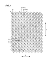
- FIG. 2 is a partially enlarged view showing a planar configuration of the solid-state imaging device 5 mounted on the digital camera shown in FIG.
- the solid-state imaging device 5 includes a large number of pixels 51 (each square block in the figure) arranged two-dimensionally in a row direction X and a column direction Y orthogonal thereto. Although all the pixels 51 are not shown in FIG. 2, in reality, approximately several million to several million pixels 51 are arranged in a two-dimensional manner. When imaging is performed by the solid-state imaging device 5, an output signal is obtained from each of the large number of pixels 51.
- Each pixel 51 includes a photoelectric conversion unit such as a photodiode and a color filter formed above the photoelectric conversion unit.
- a pixel “R” is attached to the pixel 51 including a color filter that transmits red light
- a letter “G” is attached to the pixel 51 that includes a color filter that transmits green light.
- the pixel 51 including the color filter that passes through is marked with the letter “B”.
- the large number of pixels 51 is an array in which a plurality of pixel rows including a plurality of pixels 51 arranged in the row direction X are arranged in the column direction Y. Then, the odd-numbered pixel rows and the even-numbered pixel rows are shifted in the row direction X by about 1 ⁇ 2 of the arrangement pitch of the pixels 51 of each pixel row.
- the array of color filters included in each pixel 51 of the odd-numbered pixel row is a Bayer array as a whole. Further, the color filter array included in each pixel 51 of the even-numbered pixel row is also a Bayer array as a whole.
- the pixels 51 in the odd-numbered rows and the pixels 51 adjacent to the lower right of the pixels 51 and detecting the same color light as the pixels 51 form a pair pixel.
- the solid-state imaging device 5 having such a pixel arrangement, it is possible to increase the sensitivity of the camera by adding the output signals of the two pixels 51 constituting the pair pixel. Further, by changing the exposure time of the two pixels 51 constituting the paired pixel and adding the output signals of the two pixels 51, the wide dynamic range of the camera can be achieved.
- phase difference pair a part of a large number of paired pixels is a pair of phase difference detection pixels (focus detection pixels) (hereinafter referred to as a phase difference pair).
- each phase difference pair is composed of a phase difference detection pixel 51R and a phase difference detection pixel 51L that are obliquely adjacent to each other.
- the phase difference detection pixel 51R receives one of a pair of light beams that have passed through different parts of the pupil region of the photographing lens 1 (for example, a light beam that has passed through the right half of the pupil region), and outputs a signal corresponding to the amount of light received. That is, the phase difference detection pixel 51 ⁇ / b> R provided in the solid-state imaging element 5 captures an image formed by one of a pair of light beams that have passed through different portions of the pupil region of the photographing lens 1.
- the other phase difference detection pixel 51L paired with the phase difference detection pixel 51R receives the other of the pair of light beams (for example, a light beam that has passed through the left half of the pupil region) and outputs a signal corresponding to the amount of light received. . That is, the phase difference detection pixel 51 ⁇ / b> L provided in the solid-state imaging device 5 captures an image formed by the other of the pair of light beams that have passed through different portions of the pupil region of the photographing lens 1.
- a plurality of pixels 51 (hereinafter referred to as imaging pixels) other than the phase difference detection pixels 51R and 51L capture an image formed by a light beam that has passed through almost all of the pupil region of the photographing lens 1. It becomes.
- a light shielding film is provided above the photoelectric conversion unit of the pixel 51, and an opening that defines a light receiving area of the photoelectric conversion unit is formed in the light shielding film.
- the center of the aperture of the imaging pixel 51 (indicated by symbol a in FIG. 2) coincides with the center of the photoelectric conversion unit of the imaging pixel 51 (center of a square block).
- the imaging pixel 51 is shown with an opening a only at one location.
- the center of the opening (indicated by symbol c in FIG. 2) of the phase difference detection pixel 51R is eccentric to the right with respect to the center of the photoelectric conversion unit of the phase difference detection pixel 51R.
- the center of the opening (indicated by symbol b in FIG. 2) of the phase difference detection pixel 51L is eccentric to the left with respect to the center of the photoelectric conversion unit of the phase difference detection pixel 51L.
- a part of the pixel 51 on which the green color filter is mounted is the phase difference detection pixel 51R or the phase difference detection pixel 51L.
- a pixel on which a color filter of another color is mounted may be used as a phase difference detection pixel.
- phase difference detection pixels 51R and the phase difference detection pixels 51L are discretely and periodically arranged in the region where the pixels 51 are arranged.
- the phase difference detection pixels 51 ⁇ / b> R are arranged at intervals of three pixels in the row direction X in a part of even-numbered pixel rows (four pixel rows arranged every three pixel rows in the example of FIG. 2). Is arranged.
- the phase difference detection pixel 51 ⁇ / b> L detects the phase difference in the row direction X in a part of the odd-numbered pixel rows (the pixel row adjacent to the pixel row including the phase difference detection pixels 51 ⁇ / b> R).
- the pixels 51R are arranged in the same cycle.
- the light received by the pixel 51L through the opening b of the light shielding film is light from the left side when viewed from the subject of the photographing lens 1 provided above the paper surface of FIG.
- the light mainly coming from the viewing direction and received by the pixel 51R through the opening c of the light shielding film is the light from the right side when viewed from the subject of the photographing lens 1, that is, the direction when the subject is viewed by the left eye.
- a captured image signal obtained by viewing the subject with the left eye can be obtained by all the phase difference detection pixels 51R, and a captured image signal obtained by viewing the subject by the right eye can be obtained by all the phase difference detection pixels 51L. be able to. For this reason, it becomes possible to obtain phase difference information by performing a correlation calculation by combining the two.
- the phase difference detection pixel 51R and the phase difference detection pixel 51L can obtain phase difference information by decentering the opening of the light shielding film in the opposite direction.
- the structure for obtaining the phase difference information is not limited to this, and a well-known structure can be adopted.
- a structure in which one elliptical microlens (top lens) common to the paired pixels is mounted may be used.
- the defocus amount calculation unit 18 illustrated in FIG. 1 uses the output signal group read from the phase difference detection pixel 51L and the phase difference detection pixel 51R to relatively compare the two images formed by the pair of light beams. A phase difference amount that is a positional deviation amount is calculated. Based on this phase difference amount, the focus adjustment state of the photographic lens 1, here the amount away from the in-focus state and its direction, that is, the defocus amount, is obtained as a distance measurement result.
- the digital camera shown in FIG. 1 can set a continuous AF mode that keeps focusing on a main subject during moving image capturing.
- a continuous AF mode for example, a period during which the solid-state imaging device 5 performs an operation imaging for live view image display, or a shutter switch included in the operation unit 14 is pressed in the moving image shooting mode to record a moving image. It is set during the period when the instruction is given.
- the defocus amount calculation unit 18 obtains from the phase difference detection pixel 51L and the phase difference detection pixel 51R by imaging every time the solid-state imaging device 5 performs imaging.
- the defocus amount is calculated using the output signal to be stored, and the calculated defocus amount is stored in the main memory 16.
- the defocus amount difference calculation unit 19 illustrated in FIG. 1 has a defocus amount obtained with respect to at least three imaging operations continuously performed by the solid-state imaging device 5. Among these, the difference between the defocus amount obtained by arbitrary imaging and the defocus amount obtained by imaging performed following the arbitrary imaging is obtained.
- the defocus amount D1 obtained by the first imaging the defocus amount D2 obtained by the second imaging, and the defocus amount obtained by the third imaging.
- the focus amount D3 is sequentially stored in the main memory 16.
- the system control unit 11 calculates the variance of a plurality of difference data (for example, ⁇ S1 and ⁇ S2) stored in the main memory 16, and performs the phase difference AF when the calculated variance is smaller than the threshold value, thereby adjusting the focus lens. Control to move to the in-focus position. Further, when the calculated variance is equal to or larger than the threshold value, the system control unit 11 performs control to make the position of the focus lens unchanged without performing phase difference AF.
- a plurality of difference data for example, ⁇ S1 and ⁇ S2
- FIG. 3 is a flowchart for explaining the operation of the digital camera shown in FIG. 1 in the continuous AF mode.
- the defocus amount calculation unit 18 captures a captured image signal output from the solid-state image sensor 5 (step S1). Then, the defocus amount calculation unit 18 calculates a defocus amount (range measurement result) using the captured image signal, and stores the calculated defocus amount in the main memory 16 (step S2).
- the system control unit 11 determines whether or not the number of defocus amounts stored in the main memory 16 is two or more, and when the number of defocus amounts is less than two (step S3: NO). The current position of the focus lens is maintained (step S9). Then, when the next imaging is performed by the solid-state imaging device 5, the process of step S1 is performed again.
- the main memory 16 can store a maximum of four defocus amounts. If four defocus amounts are already stored, the latest defocus amount is the oldest one. Overwritten and stored.
- the defocus amount difference calculation unit 19 calculates the difference ⁇ S between the latest defocus amount and the next new defocus amount among the defocus amounts stored in the main memory 16. Is stored in the main memory 16 (step S4).
- the main memory 16 can store, for example, a maximum of three differences ⁇ S, and when three ⁇ S are already stored, the oldest one is overwritten and stored.
- step S5 determines whether or not the number of ⁇ S stored in the main memory 16 is two or more, and when the number of ⁇ S is less than two (step S5: NO), The position is maintained as it is (step S9). Then, when the next imaging is performed by the solid-state imaging device 5, the process of step S1 is performed again.
- step S5 the system control unit 11 calculates a variance of a plurality of ⁇ S stored in the main memory 16 (step S6), and if the calculated variance is equal to or greater than a threshold value (step S7: YES) ) Maintain the current position of the focus lens. On the other hand, if the calculated variance is less than the threshold (step S7: NO), in step S8, focus control is performed by phase difference AF that moves the focus lens to the focus position using the defocus amount.
- FIG. 5, and FIG. 6 are diagrams for explaining specific examples of the difference in defocus amount obtained in step S4 in FIG. 3 and the variance of the difference.
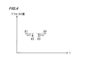
- 4 to 6 are graphs showing the defocus amount obtained from the output signal of the phase difference detection pixel in each frame data of the moving image along the time axis t.
- the graph of FIG. 4 shows a state where there is not much difference between the defocus amounts # 1, # 2, # 3, and # 4 in the frame order.
- the focus lens is moved to the in-focus position based on the defocus amount # 4, so that the main subject can be focused in the next imaging. .
- step S8 the focus lens is moved to the in-focus position based on the defocus amount # 4, so that the main subject can be focused in the next imaging.
- step S8 the system control unit 11 calculates an average value of ⁇ S1, ⁇ S2, and ⁇ S3 (corresponding to the movement amount of the main subject), and a value obtained by adding this average value to the defocus amount # 4. It is preferable to move the focus lens using a defocus amount. By doing so, it becomes possible to focus on the destination of the main subject at the time of the next imaging.
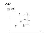
- the defocus amount oscillates as the defocus amount increases or decreases with time.
- ⁇ S1 # 2- # 1 is a positive value
- ⁇ S2 # 3- # 2 is a negative value
- ⁇ S3 # 4- # 3 is a positive value
- the dispersion of ⁇ S is large.
- the threshold used for the determination in step S7 depends on the chip area of the solid-state imaging device 5, the interval (period) in which the pixels for detecting the phase difference are provided, the lens performance, and the like. It is sufficient to determine it.
- step S3 NO and step S5: NO in FIG. 3
- the focus lens is not moved, so that it is not possible to determine whether to continue or stop the focusing operation. It is possible to prevent the photographer from feeling uncomfortable by suppressing changes in the captured image.
- the number of ⁇ S necessary for calculating the variance is four, in this case, after the first imaging after the setting of the continuous AF mode, based on the defocus amount obtained by the imaging. To move the focus lens.
- the focus lens is moved based on the average value of the defocus amount obtained by the first imaging and the defocus amount obtained by the second imaging.
- the focus lens is moved based on the median value when these three defocus amounts are arranged in order of size.
- the defocus amount obtained by the first imaging is moved based on the average value of the obtained defocus amounts or the average value of two defocus amounts excluding the maximum value and the minimum value among these four defocus amounts.
- the number of ⁇ S becomes four, so whether or not the focus control is performed is determined according to the dispersion of ⁇ S.
- the numerical information for which the dispersion is obtained is not limited to the defocus amount, and the defocus amount is not limited. Anything corresponding to the amount may be used.
- a phase difference amount obtained as a result of correlation calculation between the output signal of the phase difference detection pixel 51R and the output signal of the phase difference detection pixel 51L may be used.
- the solid-state imaging device 5 of FIG. 2 has been described as an example.
- the present invention is not limited to this, and can be applied to a case where each pixel is arranged in a square lattice.
- the pair pixel of the phase difference detection pixel is the G filter mounted pixel
- the above described also when the R filter mounted pixel is the phase difference detection pixel or the B filter mounted pixel is the phase difference detection pixel. Embodiments can be applied.
- the phase difference detection pixel pair is the closest pixel of the same color, but it is not necessary to be the closest pixel.
- it may be a pixel pair that is separated by about 1 pixel or 2 pixels.
- phase difference detection pixels are simultaneously formed on the light receiving surface of the image sensor, and phase difference data is also simultaneously read from the phase difference detection pixels by imaging with the image sensor.
- the configuration is not limited to this configuration, and a phase difference detection element in which phase difference detection pixels are formed is provided separately from the image sensor, and incident light from the photographing lens is divided into two, and one is received by the image sensor. It is also possible to apply to the configuration in which the other is received by the phase difference detecting element.
- Such a program may be provided as a program for causing a computer to execute the processing shown in FIG.
- a program is recorded on a non-transitory recording medium in which the program can be read by a computer.
- Such “computer-readable recording medium” includes, for example, an optical medium such as a CD-ROM (Compact Disc-ROM), a magnetic recording medium such as a memory card, and the like.
- Such a program can also be provided by downloading via a network.
- the digital camera has been described as an embodiment of the imaging apparatus of the present invention, but the configuration of the imaging apparatus is not limited to this.
- a built-in or external PC camera or a portable terminal device having a photographing function as described below can be used as another imaging device of the present invention.
- Examples of the mobile terminal device that is an embodiment of the imaging device of the present invention include a mobile phone, a smartphone, a PDA (Personal Digital Assistants), and a portable game machine.
- a smartphone will be described as an example, and will be described in detail with reference to the drawings.
- FIG. 7 shows an appearance of a smartphone 200 that is an embodiment of the imaging apparatus of the present invention.
- a smartphone 200 illustrated in FIG. 7 includes a flat housing 201, and a display input in which a display panel 202 as a display unit and an operation panel 203 as an input unit are integrated on one surface of the housing 201. Part 204 is provided.
- Such a housing 201 includes a speaker 205, a microphone 206, an operation unit 207, and a camera unit 208.
- the configuration of the housing 201 is not limited thereto, and for example, a configuration in which the display unit and the input unit are independent can be employed, or a configuration having a folding structure and a slide mechanism can be employed.
- FIG. 8 is a block diagram showing a configuration of the smartphone 200 shown in FIG.
- the main components of the smartphone include a wireless communication unit 210, a display input unit 204, a call unit 211, an operation unit 207, a camera unit 208, a storage unit 212, and an external input / output unit. 213, a GPS (Global Positioning System) receiving unit 214, a motion sensor unit 215, a power supply unit 216, and a main control unit 220.
- a wireless communication function for performing mobile wireless communication via a base station device BS (not shown) and a mobile communication network NW (not shown) is provided.
- the wireless communication unit 210 performs wireless communication with the base station apparatus BS accommodated in the mobile communication network NW according to an instruction from the main control unit 220. Using this wireless communication, transmission and reception of various file data such as audio data and image data, e-mail data, and reception of Web data and streaming data are performed.
- the display input unit 204 displays images (still images and moving images), character information, and the like, visually transmits information to the user under the control of the main control unit 220, and detects user operations on the displayed information.
- a so-called touch panel which includes a display panel 202 and an operation panel 203.
- the display panel 202 uses an LCD (Liquid Crystal Display), an OELD (Organic Electro-Luminescence Display), or the like as a display device.
- LCD Liquid Crystal Display
- OELD Organic Electro-Luminescence Display
- the operation panel 203 is a device that is placed so that an image displayed on the display surface of the display panel 202 is visible and detects one or more coordinates operated by a user's finger or stylus.
- a detection signal generated due to the operation is output to the main control unit 220.
- the main control unit 220 detects an operation position (coordinates) on the display panel 202 based on the received detection signal.
- the display panel 202 and the operation panel 203 of the smartphone 200 exemplified as an embodiment of the imaging apparatus of the present invention integrally form a display input unit 204.
- the arrangement 203 covers the display panel 202 completely.
- the operation panel 203 may have a function of detecting a user operation even in an area outside the display panel 202.
- the operation panel 203 includes a detection area (hereinafter referred to as a display area) for an overlapping portion that overlaps the display panel 202 and a detection area (hereinafter, a non-display area) for an outer edge portion that does not overlap the other display panel 202. May be included).
- the operation panel 203 may include two sensitive areas of the outer edge portion and the other inner portion. Further, the width of the outer edge portion is appropriately designed according to the size of the housing 201 and the like.
- the position detection method employed in the operation panel 203 include a matrix switch method, a resistance film method, a surface acoustic wave method, an infrared method, an electromagnetic induction method, a capacitance method, and the like. You can also
- the call unit 211 includes a speaker 205 and a microphone 206, converts user's voice input through the microphone 206 into voice data that can be processed by the main control unit 220, and outputs the voice data to the main control unit 220. 210 or the audio data received by the external input / output unit 213 is decoded and output from the speaker 205.
- the speaker 205 can be mounted on the same surface as the display input unit 204 and the microphone 206 can be mounted on the side surface of the housing 201.
- the operation unit 207 is a hardware key using a key switch or the like, and receives an instruction from the user.
- the operation unit 207 is mounted on the side surface of the housing 201 of the smartphone 200 and is turned on when pressed with a finger or the like, and is turned off by a restoring force such as a spring when the finger is released. It is a push button type switch.
- the storage unit 212 includes a control program and control data of the main control unit 220, application software, address data that associates the name and telephone number of a communication partner, transmitted / received e-mail data, Web data downloaded by Web browsing, The downloaded content data is stored, and streaming data and the like are temporarily stored.
- the storage unit 212 includes an internal storage unit 217 built in the smartphone and an external storage unit 218 having a removable external memory slot.
- Each of the internal storage unit 217 and the external storage unit 218 constituting the storage unit 212 includes a flash memory type (hard memory type), a hard disk type (hard disk type), a multimedia card micro type (multimedia card micro type), This is realized using a storage medium such as a card type memory (for example, MicroSD (registered trademark) memory), a RAM (Random Access Memory), a ROM (Read Only Memory), or the like.
- a flash memory type hard memory type
- hard disk type hard disk type
- multimedia card micro type multimedia card micro type
- a storage medium such as a card type memory (for example, MicroSD (registered trademark) memory), a RAM (Random Access Memory), a ROM (Read Only Memory), or the like.
- the external input / output unit 213 serves as an interface with all external devices connected to the smartphone 200, and communicates with other external devices (for example, universal serial bus (USB), IEEE 1394, etc.) or a network.
- external devices for example, universal serial bus (USB), IEEE 1394, etc.
- a network for example, the Internet, wireless LAN, Bluetooth (registered trademark), RFID (Radio Frequency Identification), Infrared Data Association (IrDA) (registered trademark), UWB (Ultra Wideband) (registered trademark) ZigBee) (registered trademark, etc.) for direct or indirect connection.
- an external device connected to the smartphone 200 for example, a wired / wireless headset, a wired / wireless external charger, a wired / wireless data port, a memory card (Memory card) connected via a card socket, or a SIM (Subscriber).
- Identity Module Card / UIM (User Identity Module Card) card external audio / video equipment connected via audio / video I / O (Input / Output) terminal, external audio / video equipment connected wirelessly, yes / no
- the external input / output unit 213 transmits data received from such an external device to each component inside the smartphone 200, or allows the data inside the smartphone 200 to be transmitted to the external device. Can do.
- the GPS receiving unit 214 receives GPS signals transmitted from the GPS satellites ST1 to STn in accordance with instructions from the main control unit 220, executes positioning calculation processing based on the received GPS signals, and calculates the latitude of the smartphone 200 Detect the position consisting of longitude and altitude.
- the GPS reception unit 214 can acquire position information from the wireless communication unit 210 or the external input / output unit 213 (for example, a wireless LAN), the GPS reception unit 214 can also detect the position using the position information.
- the motion sensor unit 215 includes, for example, a three-axis acceleration sensor, and detects the physical movement of the smartphone 200 in accordance with an instruction from the main control unit 220. By detecting the physical movement of the smartphone 200, the moving direction and acceleration of the smartphone 200 are detected. The detection result is output to the main control unit 220.
- the power supply unit 216 supplies power stored in a battery (not shown) to each unit of the smartphone 200 in accordance with an instruction from the main control unit 220.
- the main control unit 220 includes a microprocessor, operates according to a control program and control data stored in the storage unit 212, and controls each unit of the smartphone 200 in an integrated manner.
- the main control unit 220 includes a mobile communication control function that controls each unit of the communication system and an application processing function in order to perform voice communication and data communication through the wireless communication unit 210.
- the application processing function is realized by the main control unit 220 operating according to the application software stored in the storage unit 212.
- Examples of the application processing function include an infrared communication function for controlling the external input / output unit 213 to perform data communication with the opposite device, an e-mail function for transmitting / receiving e-mails, and a web browsing function for browsing web pages. .
- the main control unit 220 has an image processing function such as displaying video on the display input unit 204 based on image data (still image or moving image data) such as received data or downloaded streaming data.
- the image processing function is a function in which the main control unit 220 decodes the image data, performs image processing on the decoding result, and displays an image on the display input unit 204.
- the main control unit 220 executes display control for the display panel 202 and operation detection control for detecting a user operation through the operation unit 207 and the operation panel 203.
- the main control unit 220 displays an icon for starting application software, a software key such as a scroll bar, or a window for creating an e-mail.
- a software key such as a scroll bar, or a window for creating an e-mail.
- the scroll bar refers to a software key for accepting an instruction to move the display portion of a large image that does not fit in the display area of the display panel 202.
- the main control unit 220 detects a user operation through the operation unit 207 or accepts an operation on the icon or an input of a character string in the input field of the window through the operation panel 203. Or a display image scroll request through a scroll bar.
- the main control unit 220 causes the operation position with respect to the operation panel 203 to overlap with the display panel 202 (display area) or other outer edge part (non-display area) that does not overlap with the display panel 202.
- a touch panel control function for controlling the sensitive area of the operation panel 203 and the display position of the software key.
- the main control unit 220 can also detect a gesture operation on the operation panel 203 and execute a preset function in accordance with the detected gesture operation.
- Gesture operation is not a conventional simple touch operation, but an operation that draws a trajectory with a finger or the like, designates a plurality of positions at the same time, or combines these to draw a trajectory for at least one of a plurality of positions. means.
- the camera unit 208 is equipped with a phase difference AF function, and has a configuration other than the external memory control unit 20, the recording medium 21, the display control unit 22, the display unit 23, and the operation unit 14 in the digital camera shown in FIG. Including.
- the captured image data generated by the camera unit 208 can be recorded in the storage unit 212 or output through the input / output unit 213 or the wireless communication unit 210.
- the camera unit 208 is mounted on the same surface as the display input unit 204, but the mounting position of the camera unit 208 is not limited to this and may be mounted on the back surface of the display input unit 204. Good.
- the camera unit 208 can be used for various functions of the smartphone 200.
- an image acquired by the camera unit 208 can be displayed on the display panel 202, or the image of the camera unit 208 can be used as one of operation inputs of the operation panel 203.
- the GPS receiving unit 214 detects a position
- the position can be detected with reference to an image from the camera unit 208.
- the optical axis direction of the camera unit 208 of the smartphone 200 is determined without using the triaxial acceleration sensor or in combination with the triaxial acceleration sensor. It is also possible to determine the current usage environment.
- the image from the camera unit 208 can also be used in the application software.
- the position information acquired by the GPS receiver 214 to the image data of the still image or the moving image, the voice information acquired by the microphone 206 (the text information may be converted into voice information by the main control unit or the like), Posture information and the like acquired by the motion sensor unit 215 can be added and recorded in the recording unit 212, or output through the input / output unit 213 and the wireless communication unit 210.
- the solid-state imaging device 5 described in FIG. 2 is used as the imaging device of the camera unit 208, and the camera unit 208 performs the processing illustrated in FIG. AF can be performed.
- the disclosed imaging apparatus is an imaging apparatus having an imaging element that captures an image of a subject through an imaging optical system including a focus lens, and the imaging element includes different parts of an imaging pixel and a pupil region of the imaging optical system.
- a plurality of phase difference detection pixels that receive the light flux that has passed therethrough, and each time an image is picked up by the image pickup device, a defocus amount using an image signal acquired by the plurality of phase difference detection pixels Obtained with respect to the numerical value information obtained for an arbitrary imaging and the imaging performed after the arbitrary imaging with respect to at least three consecutive imaging operations.
- the variance of the plurality of differences obtained by the difference calculation unit is smaller than a threshold value
- the calculation unit calculates the difference from the numerical information. Using the numerical information is moved to the focus position of the focus lens, when the dispersion is not less than the threshold, in which a control unit that performs control for unchanged the position of the focus lens.
- control unit is configured to perform the at least three times when the variance of the plurality of differences obtained by the difference calculation unit is smaller than a threshold value and the signs of the plurality of differences are all the same.
- the focus lens is moved to the in-focus position based on the numerical information calculated for the last image of the images and the plurality of differences.
- control unit sets the position of the focus lens from the time when the focus lens is continuously set to the mode in which the focus lens is continuously controlled until the imaging is performed at least three times. It will be immutable.
- the disclosed imaging device is set to the mode from the time when the control unit is set to a mode in which focus control of the focus lens is continuously performed until the imaging is performed at least three times.
- the position of the focus lens is controlled on the basis of the numerical information obtained by imaging performed from the above.
- the imaging element includes the plurality of phase difference detection pixels.
- the disclosed focus control method of an imaging device is focus control of an imaging device having an imaging device that images a subject through an imaging optical system including a focus lens, the imaging device including an imaging pixel and the imaging
- a plurality of phase difference detection pixels that receive light beams that have passed through different parts of the pupil region of the optical system, and are obtained by imaging with the plurality of phase difference detection pixels each time imaging is performed by the imaging element.
- An arithmetic step for calculating numerical information corresponding to the defocus amount using an image signal, and the numerical information obtained for an arbitrary imaging and a line after the arbitrary imaging for at least three consecutive imaging operations.
- a difference calculation step for obtaining a difference from the numerical information obtained for imaging, and a variance of the plurality of differences obtained in the difference calculation step is smaller than a threshold value.
- the disclosed focus control program is a program for performing focus control of the focus lens in an imaging apparatus having an image sensor that images a subject through an imaging optical system including a focus lens. And a plurality of phase difference detection pixels that receive light beams that have passed through different portions of the pupil region of the imaging optical system, and each time the imaging device performs imaging, the plurality of phase difference detection pixels A calculation step of calculating numerical information corresponding to a defocus amount using an image signal obtained by imaging, and the numerical information obtained for an arbitrary imaging with respect to at least three consecutive imaging operations and the above The difference calculation step for obtaining the difference from the numerical information obtained for the imaging performed after arbitrary imaging, and the difference calculation step When the variance of the difference in number is smaller than a threshold value, the focus lens is moved to the in-focus position using the numerical information calculated in the calculation step. When the variance is equal to or greater than the threshold value, the focus lens A program for causing a computer to execute a control step for performing a control for making the position of the invariant.
- the determination can be accurately performed. For this reason, the possibility that an image that is greatly out of focus will be captured is reduced.
- the image pickup apparatus can appropriately determine whether to continue or stop the focus follow-up operation when performing the continuous AF in the phase difference AF method. It is useful to apply.
Landscapes
- Physics & Mathematics (AREA)
- Engineering & Computer Science (AREA)
- Multimedia (AREA)
- Signal Processing (AREA)
- General Physics & Mathematics (AREA)
- Optics & Photonics (AREA)
- Spectroscopy & Molecular Physics (AREA)
- Studio Devices (AREA)
- Focusing (AREA)
- Automatic Focus Adjustment (AREA)
Abstract
合焦動作を継続するか中止するかの判断を適切に行う撮像装置及びその合焦方法と合焦制御プログラムを提供する。位相差検出用画素と撮像用画素を含む撮像素子5を有するデジタルカメラは、撮像素子5により撮像を行う毎に、位相差検出用画素により撮像して得られる画像信号を用いてデフォーカス量を演算し、連続して行われる少なくとも3回の撮像に対し、任意の撮像について得たデフォーカス量と任意の撮像の後に行われる撮像について得たデフォーカス量との差分を求め、求めた複数の差分の分散が閾値より小さい場合に、上記デフォーカス量を利用した位相差AFを行い、分散が閾値以上の場合には位相差AFを行わない。
Description
本発明は、位相差AF方式により被写体に合焦させる撮像装置及びその合焦方法と合焦制御プログラムに関する。
デジタルスチルカメラ等の撮像装置に搭載されるAF(オートフォーカス)方式には、主として位相差AF方式とコントラストAF方式の2つの方式がある。このうち、前者は、合焦速度が速いという利点があり、一眼レフカメラ等に多く採用されている。
しかし、位相差AF方式により主要被写体までの測距を複数回行い、この複数回の測距結果を用いてフォーカスレンズの合焦動作を行うとき、各々の測距結果がばらつくことがある。また、カメラをパンニングしたときには主要被写体までの距離が急激に変化してしまうことがある。この様な場合にも、位相差AF方式の測距結果に基づいてフォーカスレンズの合焦動作を行うと、フォーカスレンズの動きが急すぎて合焦動作が不適切になり、ピンボケした画像が撮像されてしまう。
そこで、例えば下記の特許文献1記載の従来技術では、所定回数の測距結果の平均値を利用して合焦動作を行うものとし、測距結果に不規則な変動が生じたときは、この不規則な測距結果を除いて合焦動作を行っている。
また、下記の特許文献2に記載の従来技術では、撮影直前の4回の測距結果を平均化して合焦動作に用いる一方、測距結果が連続して大きく変化した場合には、オートフォーカス動作の追従を中止している。
更に、下記の特許文献3に記載の従来技術では、測距結果の変化が大きい場合、カメラのパンニングが原因だと判断して、オートフォーカス動作を追従動作させない様にしている。
位相差AF方式で被写体に合焦させ撮影を行う場合、主要被写体が静止物であればあまり問題は生じない。しかし、主要被写体が移動体の場合や、カメラをパンニングするなどしてカメラに対し相対的に主要被写体が移動する場合に、主要被写体に合焦した画像を撮影するのが難しい。
従来技術の様に、複数の測距結果を平均したり、測距結果の変化が大きい場合にはオートフォーカスの追従動作を中止したりすることで、ピンボケ画像が撮影されてしまうことをある程度回避することができる。
しかし、どのような時に測距結果の平均値で合焦動作を行ったり、どのような時にオートフォーカスの追従動作を中止したりしたら良いのかの判断基準が明確でないため、大きくピントの外れた画像が撮影されてしまうことがある。
本発明の目的は、新規で適切な判断基準を用いて、位相差AF方式で合焦動作を行い、或いは合焦動作の追従を中止することができる撮像装置及びその合焦方法と合焦制御プログラムを提供することにある。
本発明の撮像装置は、フォーカスレンズを含む撮像光学系を通して被写体を撮像する撮像素子を有する撮像装置であって、上記撮像素子は、撮像用画素と、上記撮像光学系の瞳領域の異なる部分を通過した光束を受光する複数の位相差検出用画素とを含み、上記撮像素子により撮像が行われる毎に、上記複数の位相差検出用画素により撮像して得られる画像信号を用いてデフォーカス量に対応する数値情報を演算する演算部と、連続して行われる少なくとも3回の撮像に対し、任意の撮像について得られた上記数値情報と上記任意の撮像の後に続けて行われる撮像について得られた上記数値情報との差分を求める差分演算部と、上記差分演算部により求められた複数の上記差分の分散が閾値より小さい場合に、上記演算部により演算された上記数値情報を利用して上記フォーカスレンズを合焦位置に移動させ、上記分散が上記閾値以上の場合に、上記フォーカスレンズの位置を不変とする制御を行う制御部とを備えるものである。
本発明の撮像装置の合焦制御方法は、フォーカスレンズを含む撮像光学系を通して被写体を撮像する撮像素子を有する撮像装置の合焦制御であって、上記撮像素子は、撮像用画素と、上記撮像光学系の瞳領域の異なる部分を通過した光束を受光する複数の位相差検出用画素とを含み、上記撮像素子により撮像を行う毎に、上記複数の位相差検出用画素により撮像して得られる画像信号を用いてデフォーカス量に対応する数値情報を演算する演算ステップと、連続して行われる少なくとも3回の撮像に対し、任意の撮像について得た上記数値情報と上記任意の撮像の後に行われる撮像について得た上記数値情報との差分を求める差分演算ステップと、上記差分演算ステップにおいて求めた複数の上記差分の分散が閾値より小さい場合に、上記演算ステップで演算した上記数値情報を利用して上記フォーカスレンズを合焦位置に移動させ、上記分散が上記閾値以上の場合に、上記フォーカスレンズの位置を不変とする制御を行う制御ステップとを備えるものである。
本発明の合焦制御プログラムは、フォーカスレンズを含む撮像光学系を通して被写体を撮像する撮像素子を有する撮像装置における上記フォーカスレンズの合焦制御を行うためのプログラムであって、上記撮像素子は、撮像用画素と、上記撮像光学系の瞳領域の異なる部分を通過した光束を受光する複数の位相差検出用画素とを含み、上記撮像素子により撮像を行う毎に、上記複数の位相差検出用画素により撮像して得られる画像信号を用いてデフォーカス量に対応する数値情報を演算する演算ステップと、連続して行われる少なくとも3回の撮像に対し、任意の撮像について得た上記数値情報と上記任意の撮像の後に行われる撮像について得た上記数値情報との差分を求める差分演算ステップと、上記差分演算ステップにおいて求めた複数の上記差分の分散が閾値より小さい場合に、上記演算ステップで演算した上記数値情報を利用して上記フォーカスレンズを合焦位置に移動させ、上記分散が上記閾値以上の場合に、上記フォーカスレンズの位置を不変とする制御を行う制御ステップとを、コンピュータに実行させるためのプログラムである。
本発明によれば、新規で適切な判断基準を用いて、位相差AF方式で合焦動作を行い、或いは合焦動作の追従を中止することができる撮像装置及びその合焦方法と合焦制御プログラムを提供することができる。
以下、本発明の一実施形態について、図面を参照して説明する。
図1は、本発明の一実施形態を説明するための撮像装置の一例としてのデジタルカメラの概略構成を示す図である。図1に示すデジタルカメラの撮像系は、撮像光学系としてのレンズ装置(撮影レンズ1と絞り2とを含む)と、レンズ装置を通して被写体を撮像するCCD型やCMOS型等の固体撮像素子5とを備えている。撮影レンズ1及び絞り2を含むレンズ装置は、カメラ本体に着脱可能又は固定となっている。
デジタルカメラの電気制御系全体を統括制御するシステム制御部11は、フラッシュ発光部12及び受光部13を制御する。また、システム制御部11は、レンズ駆動部8を制御して撮影レンズ1に含まれるフォーカスレンズの位置を調整したり、撮影レンズ1に含まれるズームレンズの位置の調整を行ったりする。更に、システム制御部11は、絞り駆動部9を介して絞り2の開口量を制御することにより、露光量の調整を行う。
また、システム制御部11は、撮像素子駆動部10を介して固体撮像素子5を駆動し、撮影レンズ1を通して撮像した被写体像を撮像画像信号として出力させる。システム制御部11には、操作部14を通してユーザからの指示信号が入力される。
デジタルカメラの電気制御系は、更に、固体撮像素子5の出力に接続された相関二重サンプリング処理等のアナログ信号処理を行うアナログ信号処理部6と、このアナログ信号処理部6から出力されるアナログ信号をデジタル信号に変換するA/D変換回路7とを備える。アナログ信号処理部6及びA/D変換回路7は、システム制御部11によって制御される。アナログ信号処理部6及びA/D変換回路7は固体撮像素子5に内蔵されることもある。
更に、このデジタルカメラの電気制御系は、メインメモリ16と、メインメモリ16に接続されたメモリ制御部15と、A/D変換回路7から出力される撮像画像信号に対し、補間演算、ガンマ補正演算、及びRGB/YC変換処理等を行って撮影画像データを生成するデジタル信号処理部17と、固体撮像素子5から出力される撮像画像信号の一部を用いてデフォーカス量を演算するデフォーカス量演算部18と、デフォーカス量演算部18により演算された2つのデフォーカス量の差分を求めるデファーカス量差分演算部19と、着脱自在の記録媒体21が接続される外部メモリ制御部20と、カメラ背面等に搭載された表示部23が接続される表示制御部22とを備えている。
メモリ制御部15、デジタル信号処理部17、デフォーカス量演算部18、デフォーカス量差分演算部19、外部メモリ制御部20、及び表示制御部22は、制御バス24及びデータバス25によって相互に接続され、システム制御部11からの指令によって制御される。
図2は、図1に示すデジタルカメラに搭載される固体撮像素子5の平面構成を示す部分拡大図である。
固体撮像素子5は、行方向X及びこれに直交する列方向Yに二次元状に配列された多数の画素51(図中の各正方形のブロック)を備えている。図2では全ての画素51は図示していないが、実際には、数百万~1千数百万個程度の画素51が二次元状に配列される。固体撮像素子5により撮像を行うと、この多数の画素51の各々から出力信号が得られる。
各画素51は、フォトダイオード等の光電変換部と、この光電変換部上方に形成されたカラーフィルタとを含む。
図2では、赤色光を透過するカラーフィルタを含む画素51には“R”の文字を付し、緑色光を透過するカラーフィルタを含む画素51には“G”の文字を付し、青色光を透過するカラーフィルタを含む画素51には“B”の文字を付している。
多数の画素51は、行方向Xに並ぶ複数の画素51からなる画素行を、列方向Yに複数個並べた配列となっている。そして、奇数行の画素行と偶数行の画素行は、各画素行の画素51の配列ピッチの略1/2、行方向Xにずれている。
奇数行の画素行の各画素51に含まれるカラーフィルタの配列は全体としてベイヤ配列となっている。また、偶数行の画素行の各画素51に含まれるカラーフィルタの配列も全体としてベイヤ配列となっている。奇数行にある画素51と、この画素51に対して右下に隣接する、この画素51と同色光を検出する画素51とがペア画素を構成する。
このような画素配列の固体撮像素子5によれば、ペア画素を構成する2つの画素51の出力信号を加算することでカメラの高感度化を図ることができる。また、ペア画素を構成する2つの画素51の露光時間を変え、かつ、この2つの画素51の出力信号を加算することでカメラの広ダイナミックレンジ化を図ることができる。
固体撮像素子5では、多数のペア画素のうちの一部を位相差検出用画素(焦点検出用画素)のペア(以下、位相差ペアという)としている。各位相差ペアは、図2の例では斜めに隣接する位相差検出用画素51Rと位相差検出用画素51Lとで構成される。
位相差検出用画素51Rは、撮影レンズ1の瞳領域の異なる部分を通過した一対の光束の一方(例えば瞳領域の右半分を通過した光束)を受光し受光量に応じた信号を出力する。つまり、固体撮像素子5に設けられた位相差検出用画素51Rは、撮影レンズ1の瞳領域の異なる部分を通過した一対の光束の一方によって形成される像を撮像するものとなる。
位相差検出用画素51Rとペアとなる他方の位相差検出用画素51Lは、上記一対の光束の他方(例えば瞳領域の左半分を通過した光束)を受光し受光量に応じた信号を出力する。つまり、固体撮像素子5に設けられた位相差検出用画素51Lは、撮影レンズ1の瞳領域の異なる部分を通過した一対の光束の他方によって形成される像を撮像するものとなる。
なお、位相差検出用画素51R,51L以外の複数の画素51(以下、撮像用画素という)は、撮影レンズ1の瞳領域のほぼ全ての部分を通過した光束によって形成される像を撮像するものとなる。
画素51の光電変換部上方には、遮光膜が設けられ、この遮光膜には、光電変換部の受光面積を規定する開口が形成されている。撮像用画素51の開口(図2において符号aで示す)の中心は、撮像用画素51の光電変換部の中心(正方形のブロックの中心)と一致している。なお、図2では、図を簡略化するために、撮像用画素51については一箇所のみに開口aを図示している。
これに対し、位相差検出用画素51Rの開口(図2において符号cで示す)の中心は、位相差検出用画素51Rの光電変換部の中心に対し右側に偏心している。位相差検出用画素51Lの開口(図2において符号bで示す)の中心は、位相差検出用画素51Lの光電変換部の中心に対して左側に偏心している。
固体撮像素子5では、緑色のカラーフィルタが搭載される画素51の一部が位相差検出用画素51R又は位相差検出用画素51Lとなっている。勿論、他の色のカラーフィルタが搭載される画素を位相差検出用画素としてもよい。
図示する例では、位相差検出用画素51Rと位相差検出用画素51Lは、それぞれ、画素51が配置される領域において離散的及び周期的に配置されている。
位相差検出用画素51Rは、図2の例では、偶数行の画素行の一部(図2の例では、3画素行おきに並ぶ4つの画素行)において、行方向Xに3つの画素おきに配置されている。位相差検出用画素51Lは、図2の例では、奇数行の画素行の一部(位相差検出用画素51Rを含む画素行の隣にある画素行)において、行方向Xに、位相差検出用画素51Rと同じ周期で配置されている。
このような構成により、遮光膜の開口bを通って画素51Lに受光される光は、図2の紙面上方に設けられる撮影レンズ1の被写体から見て左側からの光、すなわち被写体を右眼で見た方向から来た光が主となり、遮光膜の開口cを通って画素51Rに受光される光は、撮影レンズ1の被写体から見て右側からの光、すなわち被写体を左眼で見た方向から来た光が主となる。
即ち、全ての位相差検出用画素51Rによって、被写体を左眼で見た撮像画像信号を得ることができ、全ての位相差検出用画素51Lによって、被写体を右眼で見た撮像画像信号を得ることができる。このため、両者を組み合わせ相関演算することで位相差情報を求めることが可能になる
なお、位相差検出用画素51Rと位相差検出用画素51Lは、遮光膜の開口を逆方向に偏心させることで位相差情報を得られるようにしている。しかし、位相差情報を得るための構造はこれに限らず、よく知られているものを採用することができる。例えば、ペア画素に共通の1つの楕円形マイクロレンズ(トップレンズ)を搭載する構造でも良い。
図1に示すデフォーカス量演算部18は、位相差検出用画素51L及び位相差検出用画素51Rから読み出される出力信号群を用いて、上記一対の光束によって形成される2つの像の相対的な位置ずれ量である位相差量を演算する。そして、この位相差量に基づいて、撮影レンズ1の焦点調節状態、ここでは合焦状態から離れている量とその方向、すなわちデフォーカス量を測距結果として求める。
デフォーカス量演算部18は、例えば固体撮像素子5の受光面を3×3=9つのAFエリアに分け、そのうちのユーザ操作等により選択された1つのAFエリアにある位相差検出用画素51L及び位相差検出用画素51Rから読み出される出力信号群を用いてデフォーカス量を求める。
図1に示すデジタルカメラは、動画撮像中に主要被写体に対してピントを合わせ続けるコンティニュアスAFモードを設定可能である。コンティニュアスAFモードは、例えば、固体撮像素子5によりライブビュー画像表示のための動作撮像を行っている期間、又は、動画撮影モードにおいて操作部14に含まれるシャッタスイッチが押されて動画記録の指示がなされている期間において設定される。
コンティニュアスAFモードに設定されているとき、デフォーカス量演算部18は、固体撮像素子5により撮像が行われる毎に、その撮像によって位相差検出用画素51L及び位相差検出用画素51Rから得られる出力信号を用いてデフォーカス量を演算し、演算したデフォーカス量をメインメモリ16に記憶する。
コンティニュアスAFモードに設定されているとき、図1に示すデフォーカス量差分演算部19は、固体撮像素子5によって連続して行われる少なくとも3回の撮像に対して得られたデフォーカス量のうち、任意の撮像によって得られたデフォーカス量と、その任意の撮像に続けて行われる撮像によって得られたデフォーカス量との差分を求める。
例えば、コンティニュアスAFモードに設定されると、1回目の撮像によって得られたデフォーカス量D1と、2回目の撮像によって得られたデフォーカス量D2と、3回目の撮像によって得られたデフォーカス量D3とが順次メインメモリ16に記憶されていく。デフォーカス量差分演算部19は、ΔS1=D2-D1とΔS2=D3-D2を演算し、これらをメインメモリ16に記憶する。なお、ΔS1=D1-D2、ΔS2=D2-D3としてもよい。
システム制御部11は、メインメモリ16に記憶された複数の差分データ(例えば、上記ΔS1とΔS2)の分散を算出し、算出した分散が閾値より小さい場合に、位相差AFを行ってフォーカスレンズを合焦位置に移動させる制御を行う。また、システム制御部11は、算出した分散が閾値以上の場合に、位相差AFを行わずにフォーカスレンズの位置を不変とする制御を行う。
次に、以上のように構成されたデジタルカメラのコンティニュアスAFモードにおける動作を説明する。
図3は、図1に示すデジタルカメラのコンティニュアスAFモード時の動作を説明するためのフローチャートである。
コンティニュアスAFモードが設定されると、デフォーカス量演算部18は、固体撮像素子5から出力される撮像画像信号を取り込む(ステップS1)。そして、デフォーカス量演算部18は、この撮像画像信号を用いてデフォーカス量(測距結果)を演算し、演算したデフォーカス量をメインメモリ16に記憶する(ステップS2)。
次に、システム制御部11が、メインメモリ16に記憶されたデフォーカス量の数が2つ以上か否かを判定し、デフォーカス量の数が2つ未満のとき(ステップS3:NO)は、フォーカスレンズの位置を現状維持とする(ステップS9)。そして、固体撮像素子5により次の撮像が行われると、ステップS1の処理が再び行われる。
本実施形態では、メインメモリ16には、最大で4つのデフォーカス量を記憶可能であり、既に4つのデフォーカス量が記憶されている場合は、最も古いものに対して最新のデフォーカス量が上書きして記憶される。
ステップS3の判定がYESのとき、デフォーカス量差分演算部19が、メインメモリ16に記憶されているデフォーカス量のうち、最新のデフォーカス量と、その次に新しいデフォーカス量との差分ΔSを算出し、これをメインメモリ16に記憶する(ステップS4)。
メインメモリ16には、上記差分ΔSを例えば最大で3つ記憶可能であり、既に3つのΔSが記憶されている場合は、最も古いものに対して最新のものが上書きして記憶される。
次に、システム制御部11は、メインメモリ16に記憶されたΔSの数が2つ以上か否かを判定し、ΔSの数が2つ未満のとき(ステップS5:NO)は、フォーカスレンズの位置を現状維持とする(ステップS9)。そして、固体撮像素子5により次の撮像が行われると、ステップS1の処理が再び行われる。
ステップS5の判定がYESのとき、システム制御部11は、メインメモリ16に記憶されている複数のΔSの分散を算出し(ステップS6)、算出した分散が閾値以上であれば(ステップS7:YES)、フォーカスレンズの位置を現状維持とする。一方、算出した分散が閾値未満であれば(ステップS7:NO)、ステップS8において、デフォーカス量を用いてフォーカスレンズを合焦位置に移動させる位相差AFによる合焦制御を行う。
図4、図5、図6は、図3のステップS4で得られるデフォーカス量の差と、その差の分散との具体例を説明するための図である。図4~図6は、動画の各フレームデータ中の位相差検出用画素の出力信号から求めたデフォーカス量を時間軸tに沿って示したグラフである。
図4のグラフは、フレーム順のデフォーカス量♯1,♯2,♯3,♯4にあまり差が無い状態を示している。この場合、ΔS1=#2-#1、ΔS2=#3-#2、ΔS3=#4-#3は、それぞれ近い値になり、ΔSの分散は小さくなる。このような場合は、合焦させている主要被写体が静止物に近く、あまり移動していないと判断できる。従って、このような場合は、ステップS8において、デフォーカス量#4に基づいてフォーカスレンズを合焦位置に移動させることで、次の撮像時において主要被写体にピントの合った撮像を行うことができる。
図5のグラフでは、時間tの経過毎に、デフォーカス量♯1,♯2,♯3,♯4が単調に増加している。この場合、ΔS1=#2-#1、ΔS2=#3-#2、及びΔS3=#4-#3はほとんど同じ値になるため、ΔSの分散は小さくなる。このような場合は、主要被写体が一定速度で移動していると判断できる。従って、ステップS8において、デフォーカス量#4に基づいてフォーカスレンズを合焦位置に移動させることで、次の撮像時において主要被写体にピントの合った撮像を行うことができる。
なお、図5のように、ΔSが全て正の値(又は負の値)であり、かつ、ΔSの分散が閾値未満であるケースでは、主要被写体が一定速度で移動していると判断できる。このため、ステップS8において、システム制御部11は、ΔS1、ΔS2、ΔS3の平均値(主要被写体の移動量に相当)を算出し、この平均値をデフォーカス量#4に加算して得られる値をデフォーカス量として、フォーカスレンズを移動させるとよい。このようにすることで、次の撮像時には、主要被写体が移動した先にピントを合わせることが可能になる。
図6のグラフでは、時間経過に従って、デフォーカス量が大きくなったり小さくなったりと、振動している。この場合、ΔS1=#2-#1は正の値になり、ΔS2=#3-#2は負の値になり、ΔS3=#4-#3は正の値になり、ΔSの分散は大きくなる。
このような状態のときに、フォーカスレンズを合焦動作させると、フォーカスレンズ位置が振動してしまう可能性が高く、実際に被写体にピントを合わせるのが困難になる。このため、図6に示すような状態のときは、ステップS9において、フォーカスレンズの位置は変えない。
ステップS7において判定に用いる閾値は、固体撮像素子5のチップ面積や位相差検出用画素を設ける間隔(周期)、レンズ性能等に依存するため、個々のカメラ(撮像装置)の設計仕様毎に実験的に定めれば良い。
以上のように、本実施形態のデジタルカメラによれば、デフォーカス量の差の分散の大小によって、位相差AFを行うか否かを決めているため、一定速度で動く主要被写体を撮影している場合でも、この状況を判定して適正なAF処理を行うことができる。単純にデフォーカス量の分散を求めるだけでは、図5のケースと図6のケースを区別することができないが、デフォーカス量の差の分散を求めることで、図5のケースと図6のケースを区別することが可能になり、適正なAF処理を行うことができる。
ΔSの分散を求めるにはΔSが複数必要であり、複数のΔSを求めるにはデフォーカス量を求めるための撮像を少なくとも3回は行う必要がある。このため、コンティニュアスAFモードに設定されてから撮像が3回行われるまでの間は、合焦動作を継続するか中止するかを判断することができない。
本実施形態のデジタルカメラでは、図3のステップS3:NO、ステップS5:NOのときは、フォーカスレンズを移動させないようにしているため、合焦動作を継続するか中止するかを判断できない期間における撮像画像の変化を抑制して、撮影者に違和感を与えてしまうのを防ぐことができる。
なお、コンティニュアスAFモードに設定されてから、ΔSの分散が算出可能になるまでの間、つまり、図3のステップS5の判定がYESになるまでの間は、それまでに求められたデフォーカス量を用いて、その時点で最適なデフォーカス量を算出し、算出したデフォーカス量に基づいてフォーカスレンズを移動させるようにしてもよい。
例えば、分散の算出に必要なΔSの数を4つとした場合、この場合は、コンティニュアスAFモードに設定されてから、1回目の撮像後は、その撮像によって得られたデフォーカス量に基づいてフォーカスレンズを移動させる。
次の2回目の撮像後は、1回目の撮像により得たデフォーカス量と2回目の撮像により得たデフォーカス量との平均値に基づいてフォーカスレンズを移動させる。
次の3回目の撮像後は、1回目の撮像により得たデフォーカス量と、2回目の撮像により得たデフォーカス量と、3回目の撮像により得たデフォーカス量との平均値、又は、これら3つのデフォーカス量を大きさ順に並べたときの中央値に基づいてフォーカスレンズを移動させる。
次の4回目の撮像後は、1回目の撮像により得たデフォーカス量と、2回目の撮像により得たデフォーカス量と、3回目の撮像により得たデフォーカス量と、4回目の撮像により得たデフォーカス量との平均値、又は、これら4つのデフォーカス量のうち、最大値と最小値を除く2つのデフォーカス量の平均値に基づいてフォーカスレンズを移動させる。
そして、5回目の撮像が行われると、ΔSの数が4つになるため、ΔSの分散に応じて合焦制御を行うか否かが決定される。
また、上述した実施形態では、デフォーカス量の差の分散によって合焦動作を継続するか否かを決めるものとしたが、分散を求める対象となる数値情報はデフォーカス量に限らず、デフォーカス量に対応するものであればよい。例えば、位相差検出用画素51Rの出力信号と位相差検出用画素51Lの出力信号との相関演算の結果得られる位相差量を用いても良い。
また、上述した実施形態では、図2の固体撮像素子5を例に説明したが、本発明はこれに限るものではなく、各画素が正方格子配列される場合にも適用可能である。また、位相差検出用画素のペア画素をGフィルタ搭載画素としたが、Rフィルタ搭載画素を位相差検出用画素としたり、Bフィルタ搭載画素を位相差検出用画素としたりする場合にも上述した実施形態を適用可能である。
また、上述した実施形態では、位相差検出用画素ペアを最隣接する同色画素としたが、最隣接である必要はなく、例えば1画素や2画素程度離れた近接画素ペアとしても良い。
更に、上述した実施形態では、図2に示す様に、撮像素子の受光面上に位相差検出用画素も同時に形成し、撮像素子による撮像によって、位相差検出用画素から位相差データも同時に読み出す構成とした。しかし、本発明はこの構成に限るものではなく、位相差検出用画素を形成した位相差検出素子を撮像素子とは別に設け、撮影レンズからの入射光を二分割し、一方を撮像素子に受光させ、他方を位相差検出素子に受光させる構成にも適用可能である。
図3に示した処理をコンピュータに実行させるためのプログラムとして提供してもよい。このようなプログラムは、当該プログラムをコンピュータが読取可能な一時的でない(non-transitory)記録媒体に記録される。このような「コンピュータ読取可能な記録媒体」は、たとえば、CD-ROM(Compact Disc-ROM)等の光学媒体や、メモリカード等の磁気記録媒体等を含む。また、このようなプログラムを、ネットワークを介したダウンロードによって提供することもできる。
以上、本発明の撮像装置の実施形態として、デジタルカメラについて説明してきたが、撮像装置の構成はこれに限定されない。本発明のその他の撮像装置としては、例えば、内蔵型又は外付け型のPC用カメラ、或いは、以下に説明するような、撮影機能を有する携帯端末装置とすることができる。
本発明の撮像装置の一実施形態である携帯端末装置としては、例えば、携帯電話機やスマートフォン、PDA(Personal Digital Assistants)、携帯型ゲーム機が挙げられる。以下、スマートフォンを例に挙げ、図面を参照しつつ、詳細に説明する。
図7は、本発明の撮像装置の一実施形態であるスマートフォン200の外観を示すものである。図7に示すスマートフォン200は、平板状の筐体201を有し、筐体201の一方の面に表示部としての表示パネル202と、入力部としての操作パネル203とが一体となった表示入力部204を備えている。また、この様な筐体201は、スピーカ205と、マイクロホン206と、操作部207と、カメラ部208とを備えている。なお、筐体201の構成はこれに限定されず、例えば、表示部と入力部とが独立した構成を採用したり、折り畳み構造やスライド機構を有する構成を採用したりすることもできる。
図8は、図7に示すスマートフォン200の構成を示すブロック図である。図8に示すように、スマートフォンの主たる構成要素として、無線通信部210と、表示入力部204と、通話部211と、操作部207と、カメラ部208と、記憶部212と、外部入出力部213と、GPS(Global Positioning System)受信部214と、モーションセンサ部215と、電源部216と、主制御部220とを備える。また、スマートフォン200の主たる機能として、図示省略の基地局装置BSと図示省略の移動通信網NWとを介した移動無線通信を行う無線通信機能を備える。
無線通信部210は、主制御部220の指示にしたがって、移動通信網NWに収容された基地局装置BSに対し無線通信を行うものである。この無線通信を使用して、音声データ、画像データ等の各種ファイルデータ、電子メールデータなどの送受信や、Webデータやストリーミングデータなどの受信を行う。
表示入力部204は、主制御部220の制御により、画像(静止画像及び動画像)や文字情報などを表示して視覚的にユーザに情報を伝達するとともに、表示した情報に対するユーザ操作を検出する、いわゆるタッチパネルであって、表示パネル202と、操作パネル203とを備える。
表示パネル202は、LCD(Liquid Crystal Display)、OELD(Organic Electro-Luminescence Display)などを表示デバイスとして用いたものである。
操作パネル203は、表示パネル202の表示面上に表示される画像を視認可能に載置され、ユーザの指や尖筆によって操作される一又は複数の座標を検出するデバイスである。このデバイスをユーザの指や尖筆によって操作すると、操作に起因して発生する検出信号を主制御部220に出力する。次いで、主制御部220は、受信した検出信号に基づいて、表示パネル202上の操作位置(座標)を検出する。
図7に示すように、本発明の撮像装置の一実施形態として例示しているスマートフォン200の表示パネル202と操作パネル203とは一体となって表示入力部204を構成しているが、操作パネル203が表示パネル202を完全に覆うような配置となっている。
このような配置を採用した場合、操作パネル203は、表示パネル202外の領域についても、ユーザ操作を検出する機能を備えてもよい。換言すると、操作パネル203は、表示パネル202に重なる重畳部分についての検出領域(以下、表示領域と称する)と、それ以外の表示パネル202に重ならない外縁部分についての検出領域(以下、非表示領域と称する)とを備えていてもよい。
なお、表示領域の大きさと表示パネル202の大きさとを完全に一致させても良いが、両者を必ずしも一致させる必要は無い。また、操作パネル203が、外縁部分と、それ以外の内側部分の2つの感応領域を備えていてもよい。更に、外縁部分の幅は、筐体201の大きさなどに応じて適宜設計されるものである。更にまた、操作パネル203で採用される位置検出方式としては、マトリクススイッチ方式、抵抗膜方式、表面弾性波方式、赤外線方式、電磁誘導方式、静電容量方式などが挙げられ、いずれの方式を採用することもできる。
通話部211は、スピーカ205やマイクロホン206を備え、マイクロホン206を通じて入力されたユーザの音声を主制御部220にて処理可能な音声データに変換して主制御部220に出力したり、無線通信部210あるいは外部入出力部213により受信された音声データを復号してスピーカ205から出力させたりするものである。また、図7に示すように、例えば、スピーカ205を表示入力部204が設けられた面と同じ面に搭載し、マイクロホン206を筐体201の側面に搭載することができる。
操作部207は、キースイッチなどを用いたハードウェアキーであって、ユーザからの指示を受け付けるものである。例えば、図7に示すように、操作部207は、スマートフォン200の筐体201の側面に搭載され、指などで押下されるとオンとなり、指を離すとバネなどの復元力によってオフ状態となる押しボタン式のスイッチである。
記憶部212は、主制御部220の制御プログラムや制御データ、アプリケーションソフトウェア、通信相手の名称や電話番号などを対応づけたアドレスデータ、送受信した電子メールのデータ、WebブラウジングによりダウンロードしたWebデータや、ダウンロードしたコンテンツデータを記憶し、またストリーミングデータなどを一時的に記憶するものである。また、記憶部212は、スマートフォン内蔵の内部記憶部217と着脱自在な外部メモリスロットを有する外部記憶部218により構成される。なお、記憶部212を構成するそれぞれの内部記憶部217と外部記憶部218は、フラッシュメモリタイプ(flash memory type)、ハードディスクタイプ(hard disk type)、マルチメディアカードマイクロタイプ(multimedia card micro type)、カードタイプのメモリ(例えば、MicroSD(登録商標)メモリ等)、RAM(Random Access Memory)、ROM(Read Only Memory)などの格納媒体を用いて実現される。
外部入出力部213は、スマートフォン200に連結される全ての外部機器とのインターフェースの役割を果たすものであり、他の外部機器に通信等(例えば、ユニバーサルシリアルバス(USB)、IEEE1394など)又はネットワーク(例えば、インターネット、無線LAN、ブルートゥース(Bluetooth)(登録商標)、RFID(Radio Frequency Identification)、赤外線通信(Infrared Data Association:IrDA)(登録商標)、UWB(Ultra Wideband)(登録商標)、ジグビー(ZigBee)(登録商標)など)により直接的又は間接的に接続するためのものである。
スマートフォン200に連結される外部機器としては、例えば、有/無線ヘッドセット、有/無線外部充電器、有/無線データポート、カードソケットを介して接続されるメモリカード(Memory card)やSIM(Subscriber Identity Module Card)/UIM(User Identity Module Card)カード、オーディオ・ビデオI/O(Input/Output)端子を介して接続される外部オーディオ・ビデオ機器、無線接続される外部オーディオ・ビデオ機器、有/無線接続されるスマートフォン、有/無線接続されるパーソナルコンピュータ、有/無線接続されるPDA、有/無線接続されるパーソナルコンピュータ、イヤホンなどがある。外部入出力部213は、このような外部機器から伝送を受けたデータをスマートフォン200の内部の各構成要素に伝達することや、スマートフォン200の内部のデータが外部機器に伝送されるようにすることができる。
GPS受信部214は、主制御部220の指示にしたがって、GPS衛星ST1~STnから送信されるGPS信号を受信し、受信した複数のGPS信号に基づく測位演算処理を実行し、当該スマートフォン200の緯度、経度、高度からなる位置を検出する。GPS受信部214は、無線通信部210や外部入出力部213(例えば、無線LAN)から位置情報を取得できる時には、その位置情報を用いて位置を検出することもできる。
モーションセンサ部215は、例えば、3軸の加速度センサなどを備え、主制御部220の指示にしたがって、スマートフォン200の物理的な動きを検出する。スマートフォン200の物理的な動きを検出することにより、スマートフォン200の動く方向や加速度が検出される。係る検出結果は、主制御部220に出力されるものである。
電源部216は、主制御部220の指示にしたがって、スマートフォン200の各部に、バッテリ(図示しない)に蓄えられる電力を供給するものである。
主制御部220は、マイクロプロセッサを備え、記憶部212が記憶する制御プログラムや制御データにしたがって動作し、スマートフォン200の各部を統括して制御するものである。また、主制御部220は、無線通信部210を通じて、音声通信やデータ通信を行うために、通信系の各部を制御する移動通信制御機能と、アプリケーション処理機能を備える。
アプリケーション処理機能は、記憶部212が記憶するアプリケーションソフトウェアにしたがって主制御部220が動作することにより実現するものである。アプリケーション処理機能としては、例えば、外部入出力部213を制御して対向機器とデータ通信を行う赤外線通信機能や、電子メールの送受信を行う電子メール機能、Webページを閲覧するWebブラウジング機能などがある。
また、主制御部220は、受信データやダウンロードしたストリーミングデータなどの画像データ(静止画像や動画像のデータ)に基づいて、映像を表示入力部204に表示する等の画像処理機能を備える。画像処理機能とは、主制御部220が、上記画像データを復号し、この復号結果に画像処理を施して、画像を表示入力部204に表示する機能のことをいう。
更に、主制御部220は、表示パネル202に対する表示制御と、操作部207、操作パネル203を通じたユーザ操作を検出する操作検出制御を実行する。表示制御の実行により、主制御部220は、アプリケーションソフトウェアを起動するためのアイコンや、スクロールバーなどのソフトウェアキーを表示したり、あるいは電子メールを作成したりするためのウィンドウを表示する。なお、スクロールバーとは、表示パネル202の表示領域に収まりきれない大きな画像などについて、画像の表示部分を移動する指示を受け付けるためのソフトウェアキーのことをいう。
また、操作検出制御の実行により、主制御部220は、操作部207を通じたユーザ操作を検出したり、操作パネル203を通じて、上記アイコンに対する操作や、上記ウィンドウの入力欄に対する文字列の入力を受け付けたり、あるいは、スクロールバーを通じた表示画像のスクロール要求を受け付ける。
更に、操作検出制御の実行により主制御部220は、操作パネル203に対する操作位置が、表示パネル202に重なる重畳部分(表示領域)か、それ以外の表示パネル202に重ならない外縁部分(非表示領域)かを判定し、操作パネル203の感応領域や、ソフトウェアキーの表示位置を制御するタッチパネル制御機能を備える。
また、主制御部220は、操作パネル203に対するジェスチャ操作を検出し、検出したジェスチャ操作に応じて、予め設定された機能を実行することもできる。ジェスチャ操作とは、従来の単純なタッチ操作ではなく、指などによって軌跡を描いたり、複数の位置を同時に指定したり、あるいはこれらを組み合わせて、複数の位置から少なくとも1つについて軌跡を描く操作を意味する。
カメラ部208は、位相差AF機能を搭載しており、図1に示したデジタルカメラにおける外部メモリ制御部20、記録媒体21、表示制御部22、表示部23、及び操作部14以外の構成を含む。カメラ部208によって生成された撮像画像データは、記憶部212に記録したり、入出力部213や無線通信部210を通じて出力したりすることができる。図9に示すにスマートフォン200において、カメラ部208は表示入力部204と同じ面に搭載されているが、カメラ部208の搭載位置はこれに限らず、表示入力部204の背面に搭載されてもよい。
また、カメラ部208はスマートフォン200の各種機能に利用することができる。例えば、表示パネル202にカメラ部208で取得した画像を表示することや、操作パネル203の操作入力のひとつとして、カメラ部208の画像を利用することができる。また、GPS受信部214が位置を検出する際に、カメラ部208からの画像を参照して位置を検出することもできる。更には、カメラ部208からの画像を参照して、3軸の加速度センサを用いずに、或いは、3軸の加速度センサと併用して、スマートフォン200のカメラ部208の光軸方向を判断することや、現在の使用環境を判断することもできる。勿論、カメラ部208からの画像をアプリケーションソフトウェア内で利用することもできる。
その他、静止画又は動画の画像データにGPS受信部214により取得した位置情報、マイクロホン206により取得した音声情報(主制御部等により、音声テキスト変換を行ってテキスト情報となっていてもよい)、モーションセンサ部215により取得した姿勢情報等などを付加して記録部212に記録したり、入出力部213や無線通信部210を通じて出力したりすることもできる。
以上のような構成のスマートフォン200においても、カメラ部208の撮像素子として図2で説明した固体撮像素子5を用い、カメラ部208が図3に示した処理を行うことで、高精度の位相差AFを行うことが可能になる。
以上説明したように、本明細書には以下の事項が開示されている。
開示された撮像装置は、フォーカスレンズを含む撮像光学系を通して被写体を撮像する撮像素子を有する撮像装置であって、上記撮像素子は、撮像用画素と、上記撮像光学系の瞳領域の異なる部分を通過した光束を受光する複数の位相差検出用画素とを含み、上記撮像素子により撮像が行われる毎に、上記複数の位相差検出用画素により撮像して得られる画像信号を用いてデフォーカス量に対応する数値情報を演算する演算部と、連続して行われる少なくとも3回の撮像に対し、任意の撮像について得られた上記数値情報と上記任意の撮像の後に続けて行われる撮像について得られた上記数値情報との差分を求める差分演算部と、上記差分演算部により求められた複数の上記差分の分散が閾値より小さい場合に、上記演算部により演算された上記数値情報を利用して上記フォーカスレンズを合焦位置に移動させ、上記分散が上記閾値以上の場合に、上記フォーカスレンズの位置を不変とする制御を行う制御部とを備えるものである。
開示された撮像装置は、上記制御部は、上記差分演算部により求められた複数の上記差分の分散が閾値より小さく、かつ、上記複数の差分の符号が全て同じ場合に、上記少なくとも3回の撮像のうちの最後の撮像について演算された上記数値情報と上記複数の差分とに基づいて上記フォーカスレンズを合焦位置に移動させるものである。
開示された撮像装置は、上記制御部は、上記フォーカスレンズの合焦制御を連続して行うモードに設定されてから上記少なくとも3回の撮像が行われるまでの間は、上記フォーカスレンズの位置を不変とするものである。
開示された撮像装置は、上記制御部が、上記フォーカスレンズの合焦制御を連続して行うモードに設定されてから上記少なくとも3回の撮像が行われるまでの間は、上記モードに設定されてから行われた撮像によって得られた上記数値情報に基づいて上記フォーカスレンズの位置を制御するものである。
開示された撮像装置は、上記撮像素子が、上記複数の位相差検出用画素を含むものである。
開示された撮像装置の合焦制御方法は、フォーカスレンズを含む撮像光学系を通して被写体を撮像する撮像素子を有する撮像装置の合焦制御であって、上記撮像素子は、撮像用画素と、上記撮像光学系の瞳領域の異なる部分を通過した光束を受光する複数の位相差検出用画素とを含み、上記撮像素子により撮像を行う毎に、上記複数の位相差検出用画素により撮像して得られる画像信号を用いてデフォーカス量に対応する数値情報を演算する演算ステップと、連続して行われる少なくとも3回の撮像に対し、任意の撮像について得た上記数値情報と上記任意の撮像の後に行われる撮像について得た上記数値情報との差分を求める差分演算ステップと、上記差分演算ステップにおいて求めた複数の上記差分の分散が閾値より小さい場合に、上記演算ステップで演算した上記数値情報を利用して上記フォーカスレンズを合焦位置に移動させ、上記分散が上記閾値以上の場合に、上記フォーカスレンズの位置を不変とする制御を行う制御ステップとを備えるものである。
開示された合焦制御プログラムは、フォーカスレンズを含む撮像光学系を通して被写体を撮像する撮像素子を有する撮像装置における上記フォーカスレンズの合焦制御を行うためのプログラムであって、上記撮像素子は、撮像用画素と、上記撮像光学系の瞳領域の異なる部分を通過した光束を受光する複数の位相差検出用画素とを含み、上記撮像素子により撮像を行う毎に、上記複数の位相差検出用画素により撮像して得られる画像信号を用いてデフォーカス量に対応する数値情報を演算する演算ステップと、連続して行われる少なくとも3回の撮像に対し、任意の撮像について得た上記数値情報と上記任意の撮像の後に行われる撮像について得た上記数値情報との差分を求める差分演算ステップと、上記差分演算ステップにおいて求めた複数の上記差分の分散が閾値より小さい場合に、上記演算ステップで演算した上記数値情報を利用して上記フォーカスレンズを合焦位置に移動させ、上記分散が上記閾値以上の場合に、上記フォーカスレンズの位置を不変とする制御を行う制御ステップとを、コンピュータに実行させるためのプログラムである。
以上述べた実施形態によれば、被写体までの測距距離のフレーム間の差分データの分散により、合焦動作を継続するか中止するかを判断するため、判断を的確に行うことができる。このため、大きくピントの外れた画像が撮像されてしまう虞が小さくなる。
本発明に係る撮像装置は、位相差AF方式でコンティニュアスAFを行う場合の合焦追従動作を継続するか中止するかの判断を適切に行うことができるため、特に動体撮影を行うカメラに適用すると有用である。
以上、本発明を特定の実施形態によって説明したが、本発明はこの実施形態に限定されるものではなく、開示された発明の技術思想を逸脱しない範囲で種々の変更が可能である。
本出願は、2012年11月22日出願の日本特許出願(特願2012-256350)に基づくものであり、その内容はここに取り込まれる。
本出願は、2012年11月22日出願の日本特許出願(特願2012-256350)に基づくものであり、その内容はここに取り込まれる。
1 撮影レンズ
5 固体撮像素子
11 システム制御部(位相差AF処理部)
17 デジタル信号処理部
18 デフォーカス量演算部(位相差AF処理部)
19 デフォーカス量差分演算部
51 画素(フォトダイオード)
51L,51R 位相差検出用画素ペア
a,b,c 遮光膜開口
5 固体撮像素子
11 システム制御部(位相差AF処理部)
17 デジタル信号処理部
18 デフォーカス量演算部(位相差AF処理部)
19 デフォーカス量差分演算部
51 画素(フォトダイオード)
51L,51R 位相差検出用画素ペア
a,b,c 遮光膜開口
Claims (6)
- フォーカスレンズを含む撮像光学系を通して被写体を撮像する撮像素子を有する撮像装置であって、
前記撮像素子は、撮像用画素と、前記撮像光学系の瞳領域の異なる部分を通過した光束を受光する複数の位相差検出用画素とを含み、
前記撮像素子により撮像が行われる毎に、前記複数の位相差検出用画素により撮像して得られる画像信号を用いてデフォーカス量に対応する数値情報を演算する演算部と、
連続して行われる少なくとも3回の撮像に対し、任意の撮像について得られた前記数値情報と前記任意の撮像の後に続けて行われる撮像について得られた前記数値情報との差分を求める差分演算部と、
前記差分演算部により求められた複数の前記差分の分散が閾値より小さい場合に、前記演算部により演算された前記数値情報を利用して前記フォーカスレンズを合焦位置に移動させ、前記分散が前記閾値以上の場合に、前記フォーカスレンズの位置を不変とする制御を行う制御部とを備える撮像装置。 - 請求項1記載の撮像装置であって、
前記制御部は、前記差分演算部により求められた複数の前記差分の分散が閾値より小さく、かつ、前記複数の差分の符号が全て同じ場合に、前記少なくとも3回の撮像のうちの最後の撮像について演算された前記数値情報と前記複数の差分とに基づいて前記フォーカスレンズを合焦位置に移動させる撮像装置。 - 請求項1又は2記載の撮像装置であって、
前記制御部は、前記フォーカスレンズの合焦制御を連続して行うモードに設定されてから前記少なくとも3回の撮像が行われるまでの間は、前記フォーカスレンズの位置を不変とする撮像装置。 - 請求項1又は2記載の撮像装置であって、
前記制御部は、前記フォーカスレンズの合焦制御を連続して行うモードに設定されてから前記少なくとも3回の撮像が行われるまでの間は、前記モードに設定されてから行われた撮像によって得られた前記数値情報に基づいて前記フォーカスレンズの位置を制御する撮像装置。 - フォーカスレンズを含む撮像光学系を通して被写体を撮像する撮像素子を有する撮像装置の合焦制御であって、
前記撮像素子は、撮像用画素と、前記撮像光学系の瞳領域の異なる部分を通過した光束を受光する複数の位相差検出用画素とを含み、
前記撮像素子により撮像を行う毎に、前記複数の位相差検出用画素により撮像して得られる画像信号を用いてデフォーカス量に対応する数値情報を演算する演算ステップと、
連続して行われる少なくとも3回の撮像に対し、任意の撮像について得た前記数値情報と前記任意の撮像の後に行われる撮像について得た前記数値情報との差分を求める差分演算ステップと、
前記差分演算ステップにおいて求めた複数の前記差分の分散が閾値より小さい場合に、前記演算ステップで演算した前記数値情報を利用して前記フォーカスレンズを合焦位置に移動させ、前記分散が前記閾値以上の場合に、前記フォーカスレンズの位置を不変とする制御を行う制御ステップとを備える合焦制御方法。 - フォーカスレンズを含む撮像光学系を通して被写体を撮像する撮像素子を有する撮像装置における前記フォーカスレンズの合焦制御を行うためのプログラムであって、
前記撮像素子は、撮像用画素と、前記撮像光学系の瞳領域の異なる部分を通過した光束を受光する複数の位相差検出用画素とを含み、
前記撮像素子により撮像を行う毎に、前記複数の位相差検出用画素により撮像して得られる画像信号を用いてデフォーカス量に対応する数値情報を演算する演算ステップと、
連続して行われる少なくとも3回の撮像に対し、任意の撮像について得た前記数値情報と前記任意の撮像の後に行われる撮像について得た前記数値情報との差分を求める差分演算ステップと、
前記差分演算ステップにおいて求めた複数の前記差分の分散が閾値より小さい場合に、前記演算ステップで演算した前記数値情報を利用して前記フォーカスレンズを合焦位置に移動させ、前記分散が前記閾値以上の場合に、前記フォーカスレンズの位置を不変とする制御を行う制御ステップとを、コンピュータに実行させるための合焦制御プログラム。
Priority Applications (3)
| Application Number | Priority Date | Filing Date | Title |
|---|---|---|---|
| CN201380061182.7A CN104813213B (zh) | 2012-11-22 | 2013-09-12 | 摄像装置及其对焦方法和对焦控制程序 |
| JP2014548485A JP5789725B2 (ja) | 2012-11-22 | 2013-09-12 | 撮像装置及びその合焦方法と合焦制御プログラム |
| US14/718,971 US9547217B2 (en) | 2012-11-22 | 2015-05-21 | Device and, method for controlling a focusing operation |
Applications Claiming Priority (2)
| Application Number | Priority Date | Filing Date | Title |
|---|---|---|---|
| JP2012-256350 | 2012-11-22 | ||
| JP2012256350 | 2012-11-22 |
Related Child Applications (1)
| Application Number | Title | Priority Date | Filing Date |
|---|---|---|---|
| US14/718,971 Continuation US9547217B2 (en) | 2012-11-22 | 2015-05-21 | Device and, method for controlling a focusing operation |
Publications (1)
| Publication Number | Publication Date |
|---|---|
| WO2014080682A1 true WO2014080682A1 (ja) | 2014-05-30 |
Family
ID=50775872
Family Applications (1)
| Application Number | Title | Priority Date | Filing Date |
|---|---|---|---|
| PCT/JP2013/074708 Ceased WO2014080682A1 (ja) | 2012-11-22 | 2013-09-12 | 撮像装置及びその合焦方法と合焦制御プログラム |
Country Status (4)
| Country | Link |
|---|---|
| US (1) | US9547217B2 (ja) |
| JP (1) | JP5789725B2 (ja) |
| CN (1) | CN104813213B (ja) |
| WO (1) | WO2014080682A1 (ja) |
Families Citing this family (4)
| Publication number | Priority date | Publication date | Assignee | Title |
|---|---|---|---|---|
| WO2018004001A1 (ja) * | 2016-06-30 | 2018-01-04 | 株式会社ニコン | カメラ |
| CN106101554B (zh) * | 2016-07-29 | 2017-08-08 | 广东欧珀移动通信有限公司 | 摄像头对焦方法、装置以及终端 |
| JP2018081224A (ja) * | 2016-11-17 | 2018-05-24 | キヤノン株式会社 | 撮像装置およびその制御方法 |
| CN112040121B (zh) * | 2020-08-19 | 2021-08-13 | 江西欧迈斯微电子有限公司 | 调焦方法、装置、存储介质及终端 |
Citations (3)
| Publication number | Priority date | Publication date | Assignee | Title |
|---|---|---|---|---|
| JP2004085843A (ja) * | 2002-08-26 | 2004-03-18 | Canon Inc | カメラ |
| JP2008187231A (ja) * | 2007-01-26 | 2008-08-14 | Nikon Corp | 画像追尾装置および撮像装置 |
| JP2012133172A (ja) * | 2010-12-22 | 2012-07-12 | Nikon Corp | カメラ |
Family Cites Families (9)
| Publication number | Priority date | Publication date | Assignee | Title |
|---|---|---|---|---|
| JP2646750B2 (ja) | 1989-05-18 | 1997-08-27 | ミノルタ株式会社 | 自動合焦カメラ |
| JP3294866B2 (ja) | 1991-02-13 | 2002-06-24 | 旭光学工業株式会社 | 自動焦点調節装置 |
| JP3143321B2 (ja) * | 1994-05-10 | 2001-03-07 | ペルマノヴァ・レーザーシステム・エービー | 強力レーザー放射線伝達用の光ファイバー・ケーブル |
| JP3500435B2 (ja) | 1994-05-19 | 2004-02-23 | 株式会社ニコン | 自動焦点調節装置および自動焦点調節方法 |
| JPH08146286A (ja) | 1994-11-18 | 1996-06-07 | Nikon Corp | 自動焦点調節カメラ |
| JP3675039B2 (ja) * | 1996-06-26 | 2005-07-27 | 株式会社ニコン | 焦点調節装置 |
| JP4321579B2 (ja) * | 2006-11-28 | 2009-08-26 | ソニー株式会社 | 撮像装置 |
| JP5317562B2 (ja) * | 2008-07-17 | 2013-10-16 | キヤノン株式会社 | 位相差検出装置、撮像装置、位相差検出方法、位相差検出プログラム |
| CN101950063B (zh) * | 2009-07-10 | 2012-08-29 | 佛山普立华科技有限公司 | 自动对焦系统及自动对焦方法 |
-
2013
- 2013-09-12 CN CN201380061182.7A patent/CN104813213B/zh active Active
- 2013-09-12 JP JP2014548485A patent/JP5789725B2/ja active Active
- 2013-09-12 WO PCT/JP2013/074708 patent/WO2014080682A1/ja not_active Ceased
-
2015
- 2015-05-21 US US14/718,971 patent/US9547217B2/en active Active
Patent Citations (3)
| Publication number | Priority date | Publication date | Assignee | Title |
|---|---|---|---|---|
| JP2004085843A (ja) * | 2002-08-26 | 2004-03-18 | Canon Inc | カメラ |
| JP2008187231A (ja) * | 2007-01-26 | 2008-08-14 | Nikon Corp | 画像追尾装置および撮像装置 |
| JP2012133172A (ja) * | 2010-12-22 | 2012-07-12 | Nikon Corp | カメラ |
Also Published As
| Publication number | Publication date |
|---|---|
| US9547217B2 (en) | 2017-01-17 |
| CN104813213B (zh) | 2017-05-17 |
| JP5789725B2 (ja) | 2015-10-07 |
| JPWO2014080682A1 (ja) | 2017-01-05 |
| CN104813213A (zh) | 2015-07-29 |
| US20150253648A1 (en) | 2015-09-10 |
Similar Documents
| Publication | Publication Date | Title |
|---|---|---|
| JP5948492B2 (ja) | 撮像装置及び合焦制御方法 | |
| JP5799178B2 (ja) | 撮像装置及び合焦制御方法 | |
| JP5982601B2 (ja) | 撮像装置及び合焦制御方法 | |
| JP6307526B2 (ja) | 撮像装置及び合焦制御方法 | |
| JP6028112B2 (ja) | 撮像装置及び合焦制御方法 | |
| JP5779726B2 (ja) | 撮像装置及び露出決定方法 | |
| JP5802846B2 (ja) | 撮像装置 | |
| JP6251851B2 (ja) | 合焦制御装置、合焦制御方法、合焦制御プログラム、レンズ装置、撮像装置 | |
| JPWO2015045683A1 (ja) | 撮像装置及び合焦制御方法 | |
| WO2015045704A1 (ja) | 撮像装置及び合焦制御方法 | |
| JP5982600B2 (ja) | 撮像装置及び合焦制御方法 | |
| WO2015122061A1 (ja) | 撮像装置及び合焦制御方法 | |
| JP5990665B2 (ja) | 撮像装置及び合焦制御方法 | |
| JP5789725B2 (ja) | 撮像装置及びその合焦方法と合焦制御プログラム | |
| WO2015146229A1 (ja) | 撮像装置及び合焦制御方法 | |
| JP6171105B2 (ja) | 撮像装置及び合焦制御方法 | |
| WO2015146228A1 (ja) | 撮像装置及び合焦制御方法 | |
| JP6236580B2 (ja) | 合焦制御装置、合焦制御方法、合焦制御プログラム、レンズ装置、撮像装置 | |
| WO2022145322A1 (ja) | 撮像装置、フォーカス制御方法、及び、フォーカス制御プログラム | |
| WO2019202983A1 (ja) | 撮像装置並びに距離計測方法、距離計測プログラム及び記録媒体 | |
| WO2013145887A1 (ja) | 撮像装置及び撮像方法 |
Legal Events
| Date | Code | Title | Description |
|---|---|---|---|
| 121 | Ep: the epo has been informed by wipo that ep was designated in this application |
Ref document number: 13856902 Country of ref document: EP Kind code of ref document: A1 |
|
| DPE1 | Request for preliminary examination filed after expiration of 19th month from priority date (pct application filed from 20040101) | ||
| ENP | Entry into the national phase |
Ref document number: 2014548485 Country of ref document: JP Kind code of ref document: A |
|
| NENP | Non-entry into the national phase |
Ref country code: DE |
|
| 122 | Ep: pct application non-entry in european phase |
Ref document number: 13856902 Country of ref document: EP Kind code of ref document: A1 |