WO2014080452A1 - 運搬車両および運搬車両用エアクリーナ - Google Patents
運搬車両および運搬車両用エアクリーナ Download PDFInfo
- Publication number
- WO2014080452A1 WO2014080452A1 PCT/JP2012/080070 JP2012080070W WO2014080452A1 WO 2014080452 A1 WO2014080452 A1 WO 2014080452A1 JP 2012080070 W JP2012080070 W JP 2012080070W WO 2014080452 A1 WO2014080452 A1 WO 2014080452A1
- Authority
- WO
- WIPO (PCT)
- Prior art keywords
- cooling air
- alternator
- electric motor
- outer cylinder
- swirling flow
- Prior art date
- Legal status (The legal status is an assumption and is not a legal conclusion. Google has not performed a legal analysis and makes no representation as to the accuracy of the status listed.)
- Ceased
Links
Images

Classifications
-
- B—PERFORMING OPERATIONS; TRANSPORTING
- B60—VEHICLES IN GENERAL
- B60K—ARRANGEMENT OR MOUNTING OF PROPULSION UNITS OR OF TRANSMISSIONS IN VEHICLES; ARRANGEMENT OR MOUNTING OF PLURAL DIVERSE PRIME-MOVERS IN VEHICLES; AUXILIARY DRIVES FOR VEHICLES; INSTRUMENTATION OR DASHBOARDS FOR VEHICLES; ARRANGEMENTS IN CONNECTION WITH COOLING, AIR INTAKE, GAS EXHAUST OR FUEL SUPPLY OF PROPULSION UNITS IN VEHICLES
- B60K11/00—Arrangement in connection with cooling of propulsion units
- B60K11/06—Arrangement in connection with cooling of propulsion units with air cooling
-
- B—PERFORMING OPERATIONS; TRANSPORTING
- B60—VEHICLES IN GENERAL
- B60K—ARRANGEMENT OR MOUNTING OF PROPULSION UNITS OR OF TRANSMISSIONS IN VEHICLES; ARRANGEMENT OR MOUNTING OF PLURAL DIVERSE PRIME-MOVERS IN VEHICLES; AUXILIARY DRIVES FOR VEHICLES; INSTRUMENTATION OR DASHBOARDS FOR VEHICLES; ARRANGEMENTS IN CONNECTION WITH COOLING, AIR INTAKE, GAS EXHAUST OR FUEL SUPPLY OF PROPULSION UNITS IN VEHICLES
- B60K7/00—Disposition of motor in, or adjacent to, traction wheel
- B60K7/0007—Disposition of motor in, or adjacent to, traction wheel the motor being electric
-
- B—PERFORMING OPERATIONS; TRANSPORTING
- B60—VEHICLES IN GENERAL
- B60P—VEHICLES ADAPTED FOR LOAD TRANSPORTATION OR TO TRANSPORT, TO CARRY, OR TO COMPRISE SPECIAL LOADS OR OBJECTS
- B60P1/00—Vehicles predominantly for transporting loads and modified to facilitate loading, consolidating the load, or unloading
- B60P1/04—Vehicles predominantly for transporting loads and modified to facilitate loading, consolidating the load, or unloading with a tipping movement of load-transporting element
-
- F—MECHANICAL ENGINEERING; LIGHTING; HEATING; WEAPONS; BLASTING
- F01—MACHINES OR ENGINES IN GENERAL; ENGINE PLANTS IN GENERAL; STEAM ENGINES
- F01P—COOLING OF MACHINES OR ENGINES IN GENERAL; COOLING OF INTERNAL-COMBUSTION ENGINES
- F01P11/00—Component parts, details, or accessories not provided for in, or of interest apart from, groups F01P1/00 - F01P9/00
- F01P11/12—Filtering, cooling, or silencing cooling-air
-
- H—ELECTRICITY
- H02—GENERATION; CONVERSION OR DISTRIBUTION OF ELECTRIC POWER
- H02K—DYNAMO-ELECTRIC MACHINES
- H02K9/00—Arrangements for cooling or ventilating
- H02K9/02—Arrangements for cooling or ventilating by ambient air flowing through the machine
- H02K9/04—Arrangements for cooling or ventilating by ambient air flowing through the machine having means for generating a flow of cooling medium
-
- B—PERFORMING OPERATIONS; TRANSPORTING
- B60—VEHICLES IN GENERAL
- B60K—ARRANGEMENT OR MOUNTING OF PROPULSION UNITS OR OF TRANSMISSIONS IN VEHICLES; ARRANGEMENT OR MOUNTING OF PLURAL DIVERSE PRIME-MOVERS IN VEHICLES; AUXILIARY DRIVES FOR VEHICLES; INSTRUMENTATION OR DASHBOARDS FOR VEHICLES; ARRANGEMENTS IN CONNECTION WITH COOLING, AIR INTAKE, GAS EXHAUST OR FUEL SUPPLY OF PROPULSION UNITS IN VEHICLES
- B60K1/00—Arrangement or mounting of electrical propulsion units
- B60K2001/003—Arrangement or mounting of electrical propulsion units with means for cooling the electrical propulsion units
- B60K2001/006—Arrangement or mounting of electrical propulsion units with means for cooling the electrical propulsion units the electric motors
-
- B—PERFORMING OPERATIONS; TRANSPORTING
- B60—VEHICLES IN GENERAL
- B60K—ARRANGEMENT OR MOUNTING OF PROPULSION UNITS OR OF TRANSMISSIONS IN VEHICLES; ARRANGEMENT OR MOUNTING OF PLURAL DIVERSE PRIME-MOVERS IN VEHICLES; AUXILIARY DRIVES FOR VEHICLES; INSTRUMENTATION OR DASHBOARDS FOR VEHICLES; ARRANGEMENTS IN CONNECTION WITH COOLING, AIR INTAKE, GAS EXHAUST OR FUEL SUPPLY OF PROPULSION UNITS IN VEHICLES
- B60K6/00—Arrangement or mounting of plural diverse prime-movers for mutual or common propulsion, e.g. hybrid propulsion systems comprising electric motors and internal combustion engines
- B60K6/20—Arrangement or mounting of plural diverse prime-movers for mutual or common propulsion, e.g. hybrid propulsion systems comprising electric motors and internal combustion engines the prime-movers consisting of electric motors and internal combustion engines, e.g. HEVs
- B60K6/42—Arrangement or mounting of plural diverse prime-movers for mutual or common propulsion, e.g. hybrid propulsion systems comprising electric motors and internal combustion engines the prime-movers consisting of electric motors and internal combustion engines, e.g. HEVs characterised by the architecture of the hybrid electric vehicle
- B60K6/46—Series type
-
- B—PERFORMING OPERATIONS; TRANSPORTING
- B60—VEHICLES IN GENERAL
- B60Y—INDEXING SCHEME RELATING TO ASPECTS CROSS-CUTTING VEHICLE TECHNOLOGY
- B60Y2200/00—Type of vehicle
- B60Y2200/10—Road Vehicles
- B60Y2200/14—Trucks; Load vehicles, Busses
- B60Y2200/142—Heavy duty trucks
-
- B—PERFORMING OPERATIONS; TRANSPORTING
- B60—VEHICLES IN GENERAL
- B60Y—INDEXING SCHEME RELATING TO ASPECTS CROSS-CUTTING VEHICLE TECHNOLOGY
- B60Y2200/00—Type of vehicle
- B60Y2200/90—Vehicles comprising electric prime movers
- B60Y2200/92—Hybrid vehicles
-
- Y—GENERAL TAGGING OF NEW TECHNOLOGICAL DEVELOPMENTS; GENERAL TAGGING OF CROSS-SECTIONAL TECHNOLOGIES SPANNING OVER SEVERAL SECTIONS OF THE IPC; TECHNICAL SUBJECTS COVERED BY FORMER USPC CROSS-REFERENCE ART COLLECTIONS [XRACs] AND DIGESTS
- Y02—TECHNOLOGIES OR APPLICATIONS FOR MITIGATION OR ADAPTATION AGAINST CLIMATE CHANGE
- Y02T—CLIMATE CHANGE MITIGATION TECHNOLOGIES RELATED TO TRANSPORTATION
- Y02T10/00—Road transport of goods or passengers
- Y02T10/60—Other road transportation technologies with climate change mitigation effect
- Y02T10/62—Hybrid vehicles
-
- Y—GENERAL TAGGING OF NEW TECHNOLOGICAL DEVELOPMENTS; GENERAL TAGGING OF CROSS-SECTIONAL TECHNOLOGIES SPANNING OVER SEVERAL SECTIONS OF THE IPC; TECHNICAL SUBJECTS COVERED BY FORMER USPC CROSS-REFERENCE ART COLLECTIONS [XRACs] AND DIGESTS
- Y10—TECHNICAL SUBJECTS COVERED BY FORMER USPC
- Y10S—TECHNICAL SUBJECTS COVERED BY FORMER USPC CROSS-REFERENCE ART COLLECTIONS [XRACs] AND DIGESTS
- Y10S903/00—Hybrid electric vehicles, HEVS
- Y10S903/902—Prime movers comprising electrical and internal combustion motors
Definitions
- the present invention relates to a transport vehicle such as a dump truck for transporting minerals mined in a mine or the like, and an air cleaner suitable for a transport vehicle.
- excavators are used to excavate large amounts of minerals and earth and sand, and large amounts of excavated minerals (crushed stones) are loaded onto large transport vehicles called dump trucks. The work is carried to the unloading site such as a port.
- sand and other impurities are often contained in the atmosphere due to the sand dust rolled up by loaders and preceding dump trucks. For this reason, if air containing dust is directly taken into the generator, the insulating coating of the generator may be worn away by the dust and the insulation resistance may be reduced. If the use of the generator is continued in a state where the insulating coating is worn, the wear progresses and the insulation disappears, and eventually the dielectric breakdown may occur, and the rotor may become unusable.
- Patent Document 1 is known as a technique for separating dust in the air without using a filter.
- Patent Document 1 describes a configuration in which a strata tube is arranged in parallel to an air cleaner in a suction portion of a cooling device in a driving system cooling device in a large dump truck. According to Patent Literature 1, dust in the cooling air can be separated by putting cooling air into the strata tube and generating a swirl flow in the strata tube.
- the cooling device of Patent Document 1 has a large number of parts, and it is not always easy to attach this cooling device to a cooling system of a transport vehicle such as a dump truck. Moreover, since the air cleaner with which the cooling device of patent document 1 was equipped with the spiral blade
- the present invention has been made in view of the above-described actual situation, and an object thereof is to provide a transport vehicle equipped with a cooling air supply device equipped with a realistic air cleaner from the viewpoint of the manufacturing process and cost. It is another object of the present invention to provide such an air cleaner itself.
- a transport vehicle includes a vehicle body provided with a loading platform on which a load is loaded, an engine mounted on the vehicle body, an alternator that is driven by the engine and generates electric power, An electric motor for traveling to which driving power based on power generation by the alternator is supplied, and a cooling air supply device that supplies cooling air to the alternator and the electric motor.
- the cooling air supply device includes: a cooling fan that sucks cooling air; an alternator side duct in which cooling air flows toward the alternator; an electric motor side duct in which cooling air flows toward the electric motor; And an air cleaner for removing dust contained in.
- the air cleaner includes a swirling flow generator that generates swirling flow in the captured cooling air, a separator that is disposed downstream of the swirling flow generator and separates dust contained in the cooling air, and the swirling flow. And an outer cylinder case for accommodating the generator and the separator.
- the swirling flow generator has a fixed shaft disposed on a central axis of the outer cylinder case, one end attached to the fixed shaft, the other end attached to the outer cylinder case, and the fixed shaft as a center. And a plurality of guide vanes provided at a predetermined angle in the rotating direction, and the plurality of guide vanes generate a swirling flow of cooling air with respect to the central axis direction of the outer cylinder case.
- the separator includes a flange attached along an inner peripheral surface of the outer cylinder case, an inner cylinder provided from an inner ring of the flange toward the upstream side in the central axis direction of the outer cylinder case, and the outer cylinder A collection pocket provided at a position facing the inner cylinder of the cylinder case. Dust contained in the cooling air is configured to be taken into the gap between the inner cylinder and the outer cylinder case by a swirling flow and stored in the collection pocket.
- the configuration of the air cleaner is simpler than in the prior art.
- the plurality of guide vanes constituting the swirling flow generator have a simple configuration in which the guide vanes are each attached to the fixed shaft and the outer case by shifting by a predetermined angle about the fixed shaft. Therefore, the manufacturing process of an air cleaner can be shortened and manufacturing cost can be reduced. That is, according to the present invention, it is possible to provide a transport vehicle equipped with a cooling air supply device equipped with a realistic air cleaner from the viewpoint of manufacturing process and cost.
- the air cleaner has a unit structure in which the swirl flow generator and the separator are each attached to the outer cylinder case. This is because the air cleaner can be easily attached and detached.
- the cooling air supply device cools the alternator by directly applying the cooling air sent from the alternator side duct to the alternator, while the cooling air sent from the electric motor side duct
- the air cleaner is indirectly applied to the electric motor to cool the electric motor, and the air cleaner is formed to have substantially the same outer diameter as the outer diameter of the alternator side duct, and its central axis is the central axis of the alternator side duct. It can be set as the structure integrated in the said alternator side duct so that it may correspond.
- the cooling air supply device cools the electric motor by directly applying the cooling air sent from the electric motor side duct to the electric motor, while the cooling air sent from the alternator side duct.
- the air cleaner is formed to have substantially the same outer diameter as the outer diameter of the electric motor side duct, and its central axis is the center of the electric motor side duct. It is good also as a structure integrated in the said electric motor side duct so that it may correspond with an axis
- the object to be cooled When the cooling air directly hits the object to be cooled (alternator or electric motor), the object to be cooled is easily damaged by dust.
- the cooling air is sent to the object to be cooled that is directly hit by the cooling air. Since the air cleaner is installed in the other duct (the alternator side duct or the electric motor side duct), the damage can be prevented.
- the air cleaner since the air cleaner is installed only in the duct where the cooling air directly hits the object to be cooled, the installation of the air cleaner can be minimized, and the number of parts and the cost can be further reduced.
- the outer diameter of the duct and the outer diameter of the air cleaner are substantially the same, when the air cleaner is incorporated in the duct, both can be integrated in appearance.
- an air cleaner for a transport vehicle is disposed on a downstream side of a swirling flow generator for generating a swirling flow in cooling air taken from the outside, and the swirling flow generator. And a separator that separates dust contained in the cooling air, and an outer case that houses the swirl flow generator and the separator.
- the swirling flow generator includes a fixed shaft disposed on a central axis of the outer cylinder case, one end attached to the fixed shaft, the other end attached to the outer cylinder case, and the fixed shaft A plurality of guide vanes provided at a predetermined angle in the direction of rotation around the center, and the plurality of guide vanes cause a swirl flow of cooling air with respect to the central axis direction of the outer case.
- the separator includes a flange attached along an inner peripheral surface of the outer cylinder case, an inner cylinder provided from an inner ring of the flange toward the upstream side in the central axis direction of the outer cylinder case, and the outer cylinder A collection pocket provided at a position facing the inner cylinder of the cylinder case. Dust contained in the cooling air is configured to be taken into a gap between the inner cylinder and the outer cylinder case by a swirling flow and stored in the collection pocket. According to this invention, it is possible to suppress pressure loss when cooling air flows. Of course, the manufacturing process can be shortened and the cost can be reduced.
- the present invention by providing the above-described configuration, it is possible to provide a transport vehicle equipped with a cooling air supply device equipped with a realistic air cleaner from the viewpoint of the manufacturing process and cost. In addition, according to the present invention, it is possible to provide an air cleaner that is realistic and suitable for being mounted on a transport vehicle.
- reference numeral 1 denotes a dump truck that is a large transport vehicle.
- the dump truck 1 loads a large amount of a heavy vehicle such as a crushed stone on the vehicle body 2 having a sturdy frame structure. It is roughly constituted by a loading platform (vessel) 3.
- the vehicle body 2 includes a frame 4, a building 5, a deck 6, a cab 7 and the like which will be described later.
- the frame 4 is a base of the vehicle body 2, and the frame 4 is formed as a strong support structure forming a can-making structure.
- the frame 4 is roughly constituted by a base frame 8 extending in the front-rear direction and an upper horizontal beam 9 disposed in the middle part of the base frame 8 in the front-rear direction.
- the base frame 8 has left and right leg portions 8A (only the left side is shown) extending in a bifurcated shape (V-shape or U-shape) toward the front, and the length direction of each leg portion (front-rear direction) ) And left and right support portions 8B (only the left side is shown) projecting upward from the middle position.
- An engine 10 described later is disposed between the left and right legs (left side 8A).
- Numeral 9 indicates an upper horizontal beam constituting the frame 4 together with the base frame 8.
- the upper horizontal beam 9 is formed in a hollow prismatic shape extending in the left-right direction, and is attached to upper ends of left and right support portions (left side 8B) constituting the base frame 8.
- the upper horizontal beam 9 extends from each support portion 8B of the base frame 8 in the left-right direction, and supports a deck 6, a cab 7, a control cabinet 11, and the like, which will be described later, from below.
- reference numeral 12 denotes left and right front wheels that are rotatably provided on the front side of the vehicle body 2.
- Each front wheel 12 constitutes a steering wheel that is steered (steered) by an operator of the dump truck 1. is there.
- the left and right front wheels 12 are formed with a tire diameter (outer diameter size) of, for example, 2 to 4 meters, as with a rear wheel 13 described later.
- Reference numeral 13 denotes left and right rear wheels rotatably provided on the rear side of the vehicle body 2.
- the rear wheels 13 constitute drive wheels of the dump truck 1 and are rotatable with respect to a rear axle housing 14 described later. It is supported by.
- Each rear wheel 13 is driven to rotate by an electric motor 15 (described later) housed in the rear axle housing 14.
- Reference numeral 14 denotes a rear axle housing provided below the rear portion of the vehicle body 2, and the rear axle housing 14 is formed as a cylindrical body extending between the left and right rear wheels 13 in the axial direction (left and right direction of the vehicle body 2). Yes.
- each electric motor 15 is accommodated in order to individually rotate the left and right rear wheels 13.
- the rotation of the output shaft of each electric motor 15 is transmitted to each rear wheel 13 at a low speed and a large torque via a gear reduction mechanism (not shown) or the like.
- An electric motor side duct 17 of a cooling air supply device 16 to be described later is connected to an intermediate portion in the axial direction of the rear axle housing 14, and each electric motor 15 is indirectly connected by cooling air supplied through the electric motor side duct 17. It is configured to be cooled.
- Reference numeral 5 denotes a building that constitutes a part of the vehicle body 2.
- the building 5 is located on the front side of the support portion 8B and is attached to the left and right legs (left side 8A). Further, the building 5 supports the deck 6 described later in cooperation with the upper horizontal beam 9 from the lower side.
- Reference numeral 6 denotes a deck provided on the upper side of the building 5.
- the deck 6 is disposed at a position higher than the front wheel 12, and forms a flat passage surface or the like on the front upper side (building 5) of the vehicle body 2. To do.
- a cab 7 described later is installed on the deck 6.
- Reference numeral 7 is a cab located on the left side of the upper end of the vehicle body 2 and positioned on the front surface of the loading platform 3, and the cab 7 is disposed on the deck 6 and is viewed from below by the upper cross beam 9 and the building 5 of the frame 4. It is supported.
- Reference numeral 10 denotes an engine mounted on the vehicle body 2 below the upper horizontal beam 9 of the frame 4.
- the engine 10 is configured by using, for example, a large diesel engine, and drives an alternator 18 described later. It is.
- Reference numeral 18 denotes an alternator driven by the engine 10, and the alternator 18 is for generating drive power output to an electric motor 15 described later, and generates, for example, three-phase AC power of about 1500 kW. .
- the alternator 18 is connected to an alternator side duct 19 of a cooling air supply device 16 to be described later, and the alternator 18 is directly cooled by cooling air supplied through the alternator side duct 19.
- Reference numeral 15 denotes a pair of electric motors for traveling provided in the rear axle housing 14.
- Each of these electric motors 15 is constituted by a large electric motor including, for example, a three-phase induction motor, a three-phase brushless DC motor, and the like, and rotationally drives the left and right rear wheels 13 independently of each other.
- each electric motor 15 is supplied with drive power based on the power generated by the alternator 18, and the rotation shaft of each electric motor 15 is rotated by the supply of the drive power.
- the rotation of the rotating shaft of each electric motor 15 is transmitted to each rear wheel 13 via a gear reduction mechanism (not shown), and the dump truck 1 travels according to the rotation of each rear wheel 13. .
- Reference numeral 11 denotes a control cabinet provided at the center of the upper end of the vehicle body 2 along the right side of the cab 7, and the control cabinet 11 is supported from below by the upper horizontal beam 9 of the frame 4.
- the control cabinet 11 accommodates an inverter that controls the electric motor 15 for traveling, a control panel that controls the current generated by the alternator 18 and the rotational speed of the engine 10, a radiator that cools cooling water for the inverter, and the like. Has been.
- control cabinet 11 serves not only to accommodate an inverter and a control panel, but also to constitute a passage for supplying cooling air to a cooling air supply device 16 described later.
- a cooling air intake port 11 ⁇ / b> A for taking outside air as cooling air is provided on the front surface of the control cabinet 11.
- a cooling air outlet 11B through which cooling air taken into the control cabinet 11 flows out (becomes an outlet for cooling air) is provided at the bottom of the control cabinet 11 so as to open.
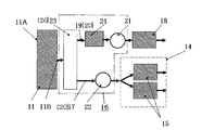
- reference numeral 16 denotes a cooling air supply device that supplies cooling air to the alternator 18 to be cooled and the electric motor 15 for traveling.
- the cooling air supply device 16 flows in from the cooling air intake port 11 A of the control cabinet 11, takes in the outside air flowing out from the cooling air outlet port 11 B as cooling air, and supplies the cooling air to the alternator 18 and the electric motor 15.
- the cooling air supply device 16 includes a cooling air supply path 20 through which cooling air flows, an air cleaner 24 that removes dust in the cooling air, an alternator side cooling fan (cooling fan) 21, and an electric motor side fan (cooling). Fan) 22.
- the cooling air supply path 20 has a collective box 23 for taking in the cooling air flowing out from the cooling air outlet 11B provided in the control cabinet 11, and a cylindrical shape branched from the collective box 23 to guide the cooling air to the alternator 18. And a cylindrical electric motor side duct 17 that branches from the collective box 23 and guides the cooling air to the electric motor 15.
- the assembly box (plenum box) 23 is attached to the lower side of the control cabinet 11 using a fixing tool (not shown) such as a bolt, and communicates with the cooling air outlet 11B of the control cabinet 11. Since the alternator side duct 19 is provided with the alternator side fan 21, the cooling air flowing into the collective box 23 flows to the alternator side duct 19 by the alternator side fan 21. Further, since the electric motor side fan 17 is provided in the electric motor side duct 17, the cooling air flowing into the collective box 23 also flows into the electric motor side duct 17 by the electric motor side fan 22. In other words, the cooling air flowing into the collecting box 23 is divided into the alternator side duct 19 and the electric motor side duct 17.
- the cooling air supply device 16 in this embodiment is configured so that the cooling air supplied into the alternator 18 is directly connected to the stator because of the shape of the cooling air supply path 20 and the arrangement of the alternator 18 and the electric motor 15. Although it directly collides with a rotor coil (not shown), the cooling air supplied into the rear axle housing 14 does not directly collide with the electric motor 15.
- the air cleaner 24 is provided in the middle of the alternator side duct 19, more specifically, between the assembly box 23 and the alternator side cooling fan 21.
- the air cleaner 24 circulates (turns) the cooling air in a spiral shape to centrifuge dust such as fine sand and dust mixed in the cooling air from the cooling air.
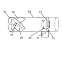
- the air cleaner 24 is roughly constituted by an outer cylinder case 25, a swirl flow generator 26, a separator 27, and the like.
- the air cleaner 24 has a unit structure in which a swirl flow generator 26 and a separator 27 are each attached to an outer cylinder case 25.
- the outer cylinder case 25 is a cylindrical member that forms an outer shell of the air cleaner 24, and is disposed coaxially with the central axis of the alternator-side duct 19 so as to extend in the cooling air outlet direction of the collective box 23. .
- the diameter of the outer cylinder case 25 and the diameter of the alternator side duct 19 are substantially the same. Therefore, when the air cleaner 24 is incorporated in the alternator-side duct 19, the alternator-side duct 19 and the outer cylinder case 25 are integrated in appearance.
- the outer casing 25 is provided with a swirl generator 26 on the upstream side of the cooling air and a separator 27 on the downstream side.
- the swirling flow generator 26 is for generating a swirling flow of cooling air around the central axis, and is arranged coaxially with the central axis of the alternator-side duct 19 (that is, on the central axis of the outer cylinder case 25).
- a plurality of (for example, four) guide blades 29 provided.
- the guide vane 29 swirls the cooling air that flows linearly (inflows along the central axis of the outer cylinder case 25) with respect to the direction of the central axis of the outer cylinder case 25 using the inclination of each vane itself. Is generated.
- Each guide blade 29 has a flat fan shape (substantially 1/4 circle shape).
- the separator 27 includes a flange 32 attached along the inner peripheral surface of the outer cylinder case 25, an inner cylinder 30 extending from the inner ring of the flange 32 to the upstream side in the central axis direction of the outer cylinder case 25, And a collection pocket 31 provided at a position facing the inner cylinder 30 of the cylinder case 25.
- a predetermined gap is formed between the outer cylinder case 25 and the inner cylinder 30.
- the dust contained in the cooling air is taken into the gap between the inner cylinder 30 and the outer cylinder case 25 while being pushed radially outward based on the centrifugal force generated by the swirling flow.
- the dust that has entered the gap is prevented from moving downstream by the flange 32, and is finally stored in the collection pocket 31.
- the cooling air from which dust has been removed by the air cleaner 24 passes through the inside of the inner cylinder 30 and is supplied to the alternator 18 so that the alternator 18 can be cooled. Further, since the air cleaner 24 prevents dust from colliding with the alternator 18, the durability of the alternator 18 can be ensured. Further, since the air cleaner 24 is configured to generate a swirling flow to centrifuge the dust, there is no concern about clogging like a filter. Therefore, it is possible to achieve both removal of dust from the cooling air and securing the amount of cooling air.
- the guide blades 29 applied to the air cleaner 24 are fan-shaped with a relatively simple shape, so that the manufacturing process is shortened compared with the conventional manufacturing of the spiral blades. Costs can be greatly reduced.
- the air cleaner 24 is provided only in the alternator-side duct 19.
- the air cleaner 24 may be provided only in the electric motor side duct 17. Further, it goes without saying that the air cleaner 24 can be used for a cooling system in general transport vehicles other than being installed in the cooling system of the dump truck 1.
Landscapes
- Engineering & Computer Science (AREA)
- Mechanical Engineering (AREA)
- Chemical & Material Sciences (AREA)
- Combustion & Propulsion (AREA)
- Transportation (AREA)
- General Engineering & Computer Science (AREA)
- Power Engineering (AREA)
- Motor Or Generator Cooling System (AREA)
- Cooling, Air Intake And Gas Exhaust, And Fuel Tank Arrangements In Propulsion Units (AREA)
- Hybrid Electric Vehicles (AREA)
- Separating Particles In Gases By Inertia (AREA)
- Cyclones (AREA)
Abstract
Description
2 車体
3 荷台
10 エンジン
15 電動モータ
16 冷却空気供給装置
17 電動モータ側ダクト
18 オルタネータ
19 オルタネータ側ダクト
21 オルタネータ側冷却ファン(冷却ファン)
22 電動モータ側ファン(冷却ファン)
24 エアクリーナ
25 外筒ケース
26 旋回流発生器
27 分離器
28 固定軸
29 案内羽根
30 内円筒
31 捕集ポケット
32 フランジ
Claims (5)
- 運搬物を積載する荷台が設けられた車体と、この車体に搭載されたエンジンと、このエンジンにより駆動され発電を行うオルタネータと、このオルタネータの発電に基づく駆動電力が供給される走行用の電動モータと、前記オルタネータおよび前記電動モータに冷却空気を供給する冷却空気供給装置と、を備えた運搬車両において、
前記冷却空気供給装置は、冷却空気を吸い込む冷却ファンと、冷却空気が前記オルタネータに向かって流れるオルタネータ側ダクトと、冷却空気が前記電動モータに向かって流れる電動モータ側ダクトと、冷却空気中に含まれるダストを除去するためのエアクリーナと、を有して構成され、
前記エアクリーナは、取り込まれた冷却空気に旋回流を発生させる旋回流発生器と、この旋回流発生器より下流側に配置され、冷却空気中に含まれるダストを分離する分離器と、前記旋回流発生器および前記分離器を収容する外筒ケースと、を有し、
前記旋回流発生器は、前記外筒ケースの中心軸上に配置される固定軸と、一端が前記固定軸に取り付けられ、他端が前記外筒ケースに取り付けられると共に、前記固定軸を中心に回転する方向に互いに所定の角度ずらして設けられた複数の案内羽根と、を有しており、前記複数の案内羽根によって、前記外筒ケースの中心軸方向に対して冷却空気の旋回流を発生させるものであり、
前記分離器は、前記外筒ケースの内周面に沿って取り付けられたフランジと、このフランジの内輪から前記外筒ケースの中心軸方向の上流側に向かって設けられた内円筒と、前記外筒ケースの前記内円筒を臨む位置に設けられた捕集ポケットと、を有し、
冷却空気中に含まれるダストは、旋回流によって前記内円筒と外筒ケースとの間の隙間に取り込まれて、前記捕集ポケットに溜められるようした
ことを特徴とする運搬車両。 - 請求項1において、
前記エアクリーナは、前記外筒ケースに前記旋回流発生器と前記分離器とをそれぞれ一基ずつ取り付けたユニット構造であることを特徴とする運搬車両。 - 請求項2において、
前記冷却空気供給装置は、前記オルタネータ側ダクトから送り出された冷却空気を前記オルタネータに直接当てて当該オルタネータを冷却する一方、前記電動モータ側ダクトから送り出された冷却空気を前記電動モータに間接的に当てて当該電動モータを冷却し、
前記エアクリーナは、前記オルタネータ側ダクトの外径と略同一外径に形成されていると共に、その中心軸が前記オルタネータ側ダクトの中心軸と一致するようにして前記オルタネータ側ダクトに組み込まれる
ことを特徴とする運搬車両。 - 請求項2において、
前記冷却空気供給装置は、前記電動モータ側ダクトから送り出された冷却空気を前記電動モータに直接当てて当該電動モータを冷却する一方、前記オルタネータ側ダクトから送り出された冷却空気を前記オルタネータに間接的に当てて当該オルタネータを冷却し、
前記エアクリーナは、前記電動モータ側ダクトの外径と略同一外径に形成されていると共に、その中心軸が前記電動モータ側ダクトの中心軸と一致するようにして前記電動モータ側ダクトに組み込まれる
ことを特徴とする運搬車両。 - 外部から取り込まれた冷却空気に旋回流を発生させる旋回流発生器と、この旋回流発生器より下流側に配置され、冷却空気中に含まれるダストを分離する分離器と、前記旋回流発生器および前記分離器を収容する外筒ケースと、備えた運搬車両用エアクリーナであって、
前記旋回流発生器は、前記外筒ケースの中心軸上に配置される固定軸と、一端が前記固定軸に取り付けられ、他端が前記外筒ケースに取り付けられると共に、前記固定軸を中心に回転する方向に互いに所定の角度ずらして設けられた複数の案内羽根と、を有しており、前記複数の案内羽根によって、前記外筒ケースの中心軸方向に対して冷却空気の旋回流を発生させるものであり、
前記分離器は、前記外筒ケースの内周面に沿って取り付けられたフランジと、このフランジの内輪から前記外筒ケースの中心軸方向の上流側に向かって設けられた内円筒と、前記外筒ケースの前記内円筒を臨む位置に設けられた捕集ポケットと、を有し、
冷却空気中に含まれるダストを、旋回流によって前記内円筒と外筒ケースとの間の隙間に取り込み、前記捕集ポケットに溜めるようした
ことを特徴とする運搬車両用エアクリーナ。
Priority Applications (3)
| Application Number | Priority Date | Filing Date | Title |
|---|---|---|---|
| PCT/JP2012/080070 WO2014080452A1 (ja) | 2012-11-20 | 2012-11-20 | 運搬車両および運搬車両用エアクリーナ |
| JP2014548353A JP5952915B2 (ja) | 2012-11-20 | 2012-11-20 | 運搬車両 |
| US14/443,740 US9415678B2 (en) | 2012-11-20 | 2012-11-20 | Transport vehicle, and transport vehicle air cleaner |
Applications Claiming Priority (1)
| Application Number | Priority Date | Filing Date | Title |
|---|---|---|---|
| PCT/JP2012/080070 WO2014080452A1 (ja) | 2012-11-20 | 2012-11-20 | 運搬車両および運搬車両用エアクリーナ |
Publications (1)
| Publication Number | Publication Date |
|---|---|
| WO2014080452A1 true WO2014080452A1 (ja) | 2014-05-30 |
Family
ID=50775658
Family Applications (1)
| Application Number | Title | Priority Date | Filing Date |
|---|---|---|---|
| PCT/JP2012/080070 Ceased WO2014080452A1 (ja) | 2012-11-20 | 2012-11-20 | 運搬車両および運搬車両用エアクリーナ |
Country Status (3)
| Country | Link |
|---|---|
| US (1) | US9415678B2 (ja) |
| JP (1) | JP5952915B2 (ja) |
| WO (1) | WO2014080452A1 (ja) |
Cited By (6)
| Publication number | Priority date | Publication date | Assignee | Title |
|---|---|---|---|---|
| WO2016104435A1 (ja) * | 2014-12-25 | 2016-06-30 | 日東工器株式会社 | エア工具 |
| JP2017064576A (ja) * | 2015-09-28 | 2017-04-06 | パナソニックIpマネジメント株式会社 | 集塵装置 |
| CN108666498A (zh) * | 2018-08-11 | 2018-10-16 | 深圳市道通科技股份有限公司 | 一种汽车诊断仪及其电池仓组件 |
| WO2019229814A1 (ja) * | 2018-05-28 | 2019-12-05 | 三菱電機株式会社 | 油分離器および冷凍サイクル装置 |
| KR102173085B1 (ko) * | 2019-10-04 | 2020-11-02 | 이정용 | 차량용 배터리팩 냉각용 공기유도장치 |
| JP2021048671A (ja) * | 2019-09-17 | 2021-03-25 | 日立建機株式会社 | ダンプトラック |
Families Citing this family (5)
| Publication number | Priority date | Publication date | Assignee | Title |
|---|---|---|---|---|
| CA2940600C (en) * | 2014-02-27 | 2017-12-19 | Komatsu Ltd. | Dump truck |
| US11505403B2 (en) | 2019-05-03 | 2022-11-22 | Oshkosh Corporation | Carry can for refuse vehicle |
| US20200346547A1 (en) * | 2019-05-03 | 2020-11-05 | Oshkosh Corporation | Auxiliary power system for electric refuse vehicle |
| US11007863B2 (en) | 2019-07-31 | 2021-05-18 | Oshkosh Corporation | Refuse vehicle with independently operational accessory system |
| US12049136B2 (en) | 2019-07-31 | 2024-07-30 | Oshkosh Corporation | Refuse vehicle with range extension |
Citations (4)
| Publication number | Priority date | Publication date | Assignee | Title |
|---|---|---|---|---|
| JPH11241369A (ja) * | 1998-02-25 | 1999-09-07 | Shin Caterpillar Mitsubishi Ltd | 建設機械の冷却装置 |
| JP2002324561A (ja) * | 2001-04-27 | 2002-11-08 | Mitsubishi Heavy Ind Ltd | 気液分離装置およびこれを利用する燃料電池発電システム |
| JP2007229913A (ja) * | 2006-02-06 | 2007-09-13 | Ikura Seiki Seisakusho Co Ltd | 工作機械および気液分離装置 |
| JP2011119670A (ja) * | 2009-10-28 | 2011-06-16 | Hiroo Hayashi | 電子機器及び電子機器収納キャビネット並びにこれらに用いられる冷却装置 |
Family Cites Families (5)
| Publication number | Priority date | Publication date | Assignee | Title |
|---|---|---|---|---|
| US4218223A (en) * | 1977-11-25 | 1980-08-19 | Donaldson Company, Inc. | Pre-cleaner for combustion engines |
| JP2507606Y2 (ja) * | 1990-07-06 | 1996-08-14 | 株式会社小松製作所 | 大型ダンプトラックの駆動系の冷却装置用エアクリ―ナ |
| US20060272621A1 (en) * | 2005-06-03 | 2006-12-07 | Acuna Henry T Sr | Cold air induction system, apparatus and method |
| US20080098998A1 (en) * | 2006-10-30 | 2008-05-01 | Dicke Paul A | Engine mounted air-to-air aftercooler |
| JP2010156276A (ja) * | 2008-12-26 | 2010-07-15 | Nippon Donarudoson Kk | エアクリーナ及び空気ろ過システム |
-
2012
- 2012-11-20 JP JP2014548353A patent/JP5952915B2/ja not_active Expired - Fee Related
- 2012-11-20 WO PCT/JP2012/080070 patent/WO2014080452A1/ja not_active Ceased
- 2012-11-20 US US14/443,740 patent/US9415678B2/en active Active
Patent Citations (4)
| Publication number | Priority date | Publication date | Assignee | Title |
|---|---|---|---|---|
| JPH11241369A (ja) * | 1998-02-25 | 1999-09-07 | Shin Caterpillar Mitsubishi Ltd | 建設機械の冷却装置 |
| JP2002324561A (ja) * | 2001-04-27 | 2002-11-08 | Mitsubishi Heavy Ind Ltd | 気液分離装置およびこれを利用する燃料電池発電システム |
| JP2007229913A (ja) * | 2006-02-06 | 2007-09-13 | Ikura Seiki Seisakusho Co Ltd | 工作機械および気液分離装置 |
| JP2011119670A (ja) * | 2009-10-28 | 2011-06-16 | Hiroo Hayashi | 電子機器及び電子機器収納キャビネット並びにこれらに用いられる冷却装置 |
Cited By (13)
| Publication number | Priority date | Publication date | Assignee | Title |
|---|---|---|---|---|
| WO2016104435A1 (ja) * | 2014-12-25 | 2016-06-30 | 日東工器株式会社 | エア工具 |
| JP2016120570A (ja) * | 2014-12-25 | 2016-07-07 | 日東工器株式会社 | エア工具 |
| TWI566890B (zh) * | 2014-12-25 | 2017-01-21 | Nitto Kohki Co | Pneumatic tools |
| CN107000185A (zh) * | 2014-12-25 | 2017-08-01 | 日东工器株式会社 | 气动工具 |
| JP2017064576A (ja) * | 2015-09-28 | 2017-04-06 | パナソニックIpマネジメント株式会社 | 集塵装置 |
| WO2019229814A1 (ja) * | 2018-05-28 | 2019-12-05 | 三菱電機株式会社 | 油分離器および冷凍サイクル装置 |
| JPWO2019229814A1 (ja) * | 2018-05-28 | 2020-12-10 | 三菱電機株式会社 | 油分離器および冷凍サイクル装置 |
| JP7012839B2 (ja) | 2018-05-28 | 2022-01-28 | 三菱電機株式会社 | 油分離器および冷凍サイクル装置 |
| CN108666498A (zh) * | 2018-08-11 | 2018-10-16 | 深圳市道通科技股份有限公司 | 一种汽车诊断仪及其电池仓组件 |
| CN108666498B (zh) * | 2018-08-11 | 2024-05-28 | 深圳市道通科技股份有限公司 | 一种汽车诊断仪及其电池仓组件 |
| JP2021048671A (ja) * | 2019-09-17 | 2021-03-25 | 日立建機株式会社 | ダンプトラック |
| JP7199328B2 (ja) | 2019-09-17 | 2023-01-05 | 日立建機株式会社 | ダンプトラック |
| KR102173085B1 (ko) * | 2019-10-04 | 2020-11-02 | 이정용 | 차량용 배터리팩 냉각용 공기유도장치 |
Also Published As
| Publication number | Publication date |
|---|---|
| JPWO2014080452A1 (ja) | 2017-01-05 |
| US20150321546A1 (en) | 2015-11-12 |
| JP5952915B2 (ja) | 2016-07-13 |
| US9415678B2 (en) | 2016-08-16 |
Similar Documents
| Publication | Publication Date | Title |
|---|---|---|
| JP5952915B2 (ja) | 運搬車両 | |
| US20250361696A1 (en) | Electric motor driven loader with electric motor powered hydraulics | |
| JP5215956B2 (ja) | ダンプトラック | |
| US8960345B2 (en) | Transporter vehicle | |
| CN103607073A (zh) | 高效冷却散热的独立三风路结构电机 | |
| GB2457144A (en) | Self propelled aircraft undercarriage assembly with cooling means | |
| CN202679216U (zh) | 一种具有自发电功能的缓速器 | |
| JP2017128880A (ja) | 締固め機械 | |
| JPH11155203A (ja) | 風力発電による車載バッテリ充電装置 | |
| CN203589918U (zh) | 高效冷却散热的独立三风路结构电机 | |
| JP6569493B2 (ja) | 車両 | |
| JP3204254U (ja) | 移動電源車 | |
| JP2019064326A (ja) | 運搬車両 | |
| JP7199328B2 (ja) | ダンプトラック | |
| CN106739776A (zh) | 电动遥控车轮 | |
| EP2933172A1 (en) | Articulated vehicle for transporting passengers with an improved driving system | |
| CN102844222A (zh) | 电驱动车辆的电能存储器的充电和/或放电的方法以及这样的车辆 | |
| JP2014134100A (ja) | 車載用発電ユニット、及び車両 | |
| WO2021019917A1 (ja) | 車載用風力発電装置 | |
| JP6120193B1 (ja) | 風力発電装置付き車両 | |
| JP3156075U (ja) | バッテリー充電装置およびそれを用いた電気自動車 | |
| JP2013216224A (ja) | 運搬車両 | |
| GB2470181A (en) | Electric vehicle having wind turbine to charge batteries | |
| JP6563369B2 (ja) | 作業機 | |
| JP5439437B2 (ja) | 電動式作業機とその給電ユニットおよび移動方法 |
Legal Events
| Date | Code | Title | Description |
|---|---|---|---|
| 121 | Ep: the epo has been informed by wipo that ep was designated in this application |
Ref document number: 12888804 Country of ref document: EP Kind code of ref document: A1 |
|
| ENP | Entry into the national phase |
Ref document number: 2014548353 Country of ref document: JP Kind code of ref document: A |
|
| WWE | Wipo information: entry into national phase |
Ref document number: 14443740 Country of ref document: US |
|
| NENP | Non-entry into the national phase |
Ref country code: DE |
|
| 122 | Ep: pct application non-entry in european phase |
Ref document number: 12888804 Country of ref document: EP Kind code of ref document: A1 |