WO2014077075A1 - 導通検査装置 - Google Patents
導通検査装置 Download PDFInfo
- Publication number
- WO2014077075A1 WO2014077075A1 PCT/JP2013/077943 JP2013077943W WO2014077075A1 WO 2014077075 A1 WO2014077075 A1 WO 2014077075A1 JP 2013077943 W JP2013077943 W JP 2013077943W WO 2014077075 A1 WO2014077075 A1 WO 2014077075A1
- Authority
- WO
- WIPO (PCT)
- Prior art keywords
- potential
- electrode plate
- reference electrode
- terminal
- electric wire
- Prior art date
- Legal status (The legal status is an assumption and is not a legal conclusion. Google has not performed a legal analysis and makes no representation as to the accuracy of the status listed.)
- Ceased
Links
Images


Classifications
-
- G—PHYSICS
- G01—MEASURING; TESTING
- G01R—MEASURING ELECTRIC VARIABLES; MEASURING MAGNETIC VARIABLES
- G01R31/00—Arrangements for testing electric properties; Arrangements for locating electric faults; Arrangements for electrical testing characterised by what is being tested not provided for elsewhere
- G01R31/50—Testing of electric apparatus, lines, cables or components for short-circuits, continuity, leakage current or incorrect line connections
- G01R31/66—Testing of connections, e.g. of plugs or non-disconnectable joints
- G01R31/68—Testing of releasable connections, e.g. of terminals mounted on a printed circuit board
- G01R31/69—Testing of releasable connections, e.g. of terminals mounted on a printed circuit board of terminals at the end of a cable or a wire harness; of plugs; of sockets, e.g. wall sockets or power sockets in appliances
-
- G—PHYSICS
- G01—MEASURING; TESTING
- G01R—MEASURING ELECTRIC VARIABLES; MEASURING MAGNETIC VARIABLES
- G01R31/00—Arrangements for testing electric properties; Arrangements for locating electric faults; Arrangements for electrical testing characterised by what is being tested not provided for elsewhere
- G01R31/50—Testing of electric apparatus, lines, cables or components for short-circuits, continuity, leakage current or incorrect line connections
- G01R31/52—Testing for short-circuits, leakage current or ground faults
-
- G—PHYSICS
- G01—MEASURING; TESTING
- G01R—MEASURING ELECTRIC VARIABLES; MEASURING MAGNETIC VARIABLES
- G01R31/00—Arrangements for testing electric properties; Arrangements for locating electric faults; Arrangements for electrical testing characterised by what is being tested not provided for elsewhere
- G01R31/50—Testing of electric apparatus, lines, cables or components for short-circuits, continuity, leakage current or incorrect line connections
- G01R31/54—Testing for continuity
-
- G—PHYSICS
- G01—MEASURING; TESTING
- G01R—MEASURING ELECTRIC VARIABLES; MEASURING MAGNETIC VARIABLES
- G01R31/00—Arrangements for testing electric properties; Arrangements for locating electric faults; Arrangements for electrical testing characterised by what is being tested not provided for elsewhere
- G01R31/50—Testing of electric apparatus, lines, cables or components for short-circuits, continuity, leakage current or incorrect line connections
- G01R31/58—Testing of lines, cables or conductors
Definitions
- the present invention relates to a continuity inspection device for electric wires such as a wire harness in which connector terminals are connected to both ends.
- a continuity test is performed in order to detect wire disconnection, terminal connection failure, and the like.
- the continuity test is performed by measuring the potential appearing at the corresponding terminal of the connector on the other end side of the electric wire in a state where the inspection voltage is applied to the terminal to be inspected of the connector on the one end side of the electric wire from the inspection device side. .
- the above-described continuity inspection is performed by fitting the connector on the inspection apparatus side to one or both connectors of the electric wire.
- the continuity is detected.
- the terminal is deformed by repeated insertion and removal of the terminal during the inspection.
- the contact on the inspection device side is opposed to the terminal of the connector at both ends of the electric wire in a non-contact state, and an arc is generated between one contact and the terminal on the one end side of the electric wire by the pulse voltage applied from the inspection device. It has been proposed to generate static electricity in an electric wire by generating a discharge that does not occur.
- JP-A-7-280864 JP H07-280864 A
- the present invention has been made in view of the above circumstances, and an object of the present invention is to determine the electrostatic potential of an electric wire charged by applying a voltage to one probe opposed to a terminal at one end of the electric wire. Conductivity that makes it easier to leak static electricity from the wire after inspection when measuring through the other probe facing the terminal at the other end of the wire and inspecting the continuity of the wire based on the result It is to provide an inspection device.
- a continuity inspection apparatus for inspecting a continuity state of an electric wire having a first terminal on one end side and a second terminal on the other end side.
- a voltage is applied to the first probe, and the surface potential of the second terminal is measured through the second probe in a state where the reference electrode plate is fixed at a potential lower than the potential of the applied voltage. Based on the measurement result Inspect the continuity of the wires.
- the surface potential of the second terminal on the other end side of the electric wire is measured through the second probe, and it is determined whether or not the electric potential corresponds to the applied voltage of the first probe, thereby inspecting the conduction state of the electric wire. be able to.
- the electrons attracted to the reference electrode plate having a lower potential than the electrostatic potential charged in the middle portion of the electric wire are the reference electrode. It is discharged from the board into the air and moves to the middle part of the wire. Then, an electron movement path is formed from the reference electrode plate to the first probe through the intermediate portion and one end of the electric wire, and an electric current flows through the movement path in a direction opposite to the electron. Static electricity (positive charge) is leaked from the wire through the route.
- the potential of static electricity generated at the first terminal on one end side of the wire by applying a voltage to the first probe can be measured with a surface potentiometer as an absolute potential with respect to the fixed potential of the reference electrode plate, floating between the wires Without being affected by the crosstalk due to the capacitance, the electrostatic potential of the electric wire can be accurately measured and reflected in the conduction state inspection.
- the distance between each terminal of the electric wire and the first probe and the second probe, and the distance between the intermediate part of the electric wire and the reference electrode plate are both accompanied by the generation of an arc. To the extent that no air discharge occurs.
- the continuity test apparatus is a continuity test apparatus for inspecting the continuity state of a plurality of electric wires each having a first terminal on one end side and a second terminal on the other end side, A plurality of first probes opposed to each of the first terminals in a non-contact state, a plurality of second probes opposed to each of the second terminals in a non-contact state, and arranged along the middle portion of the plurality of electric wires A reference electrode plate. Then, a voltage is applied to one of the first probes, and the second terminal of the wire corresponding to at least one of the first probes in a state where the reference electrode plate is fixed at a potential lower than the potential of the applied voltage. The surface potential of one or more second terminals including the above is measured through the second probe, and the conduction state of the plurality of electric wires is inspected based on the measurement result.
- the surface potential of the second terminal on the other end side of the plurality of electric wires including the electric wire is the same potential (however, the potential of the reference electrode plate is not Is not), there is a short-circuit between wires or terminals between one wire and another wire, or the continuity test target connects multiple wires to the other end of a wire.
- the result of the inspection is that the connection circuit is the same.
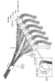
- FIG. 1 is an explanatory diagram illustrating a basic configuration of a continuity test apparatus according to an embodiment.
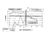
- FIG. 2 is a perspective view showing a main part of the continuity testing apparatus shown in FIG. 3 shows that the surface potential of the terminal at the other end of the wire measured by the measuring instrument of FIG. 1 is divided into a case where the reference electrode plate is set to the ground potential and a case where the reference electrode plate is floated from the ground potential. It is the graph plotted according to the distance with the intermediate part.
- FIG. 4 is a graph showing the relationship between the surface potential of the terminal at the other end of the electric wire and the size of the reference electrode plate measured by the measuring instrument of FIG.
- the continuity inspection apparatus 1 is an apparatus that performs continuity inspection of electric wires 51 and 53 such as a wire harness (not shown) of a vehicle.
- first terminals 51a and 53a are connected to one end side of each of the electric wires 51 and 53 (core wire (not shown) covered with an insulating coating (not shown)), and the other end side is connected to the other end side.
- the second terminals 51b and 53b are connected.
- First terminals 51a and 53a on one end side of the electric wires 51 and 53 are accommodated in the first connector 55a.
- the second terminals 51b and 53b on the other end side are accommodated in the second connector 55b.
- the continuity testing apparatus 1 includes a power supply side connector receiver 3 in which the first connector 55 a is accommodated, a test side connector receiver 5 in which the second connector 55 b is accommodated, and intermediate portions 51 c and 53 c of the electric wires 51 and 53.
- the reference electrode plate 7 is provided.
- the continuity testing apparatus 1 includes a power supply unit 9 that energizes the electric wires 51 and 53 to be inspected and a first switching device 11 that switches the electric wires 51 and 53 to be energized.
- the continuity testing apparatus 1 includes a measuring instrument 13 that measures the surface potential of the second terminals 51b and 53b on the other end side of the electric wires 51 and 53 to be inspected, and second terminals 51b and 53b that are targets of measuring the surface potential. And a second switching device 15 for switching between.
- the power supply side connector receiver 3 includes two power supply probes 3a and 3b (first probes).
- the front end surfaces of the power supply probes 3a and 3b face the front ends of the first terminals 51a and 53a of the first connector 55a accommodated in the power supply side connector receiver 3 in a non-contact state.
- Each of the power supply probes 3 a and 3 b is connected to the power supply unit 9 via the first switch 11.
- a voltage of a predetermined magnitude is applied from the power supply unit 9 to the power supply probes 3 a and 3 b connected to the power supply unit 9 via the first switch 11.
- the power supply probes 3a and 3b to which a voltage of a predetermined magnitude is applied generate an air discharge without generating an arc between the first terminals 51a and 53a of the first connector 55a facing each other.
- the electric wires 51 and 53 connected to 51a and 53a are charged with static electricity.
- the inspection-side connector receiver 5 includes two inspection probes 5a and 5b (second probes).
- the tip surfaces of the inspection probes 5a and 5b face the tips of the second terminals 51b and 53b of the second connector 55b accommodated in the inspection-side connector receiver 5 in a non-contact state.
- the inspection probes 5 a and 5 b are connected to the measuring instrument 13 via the second switching machine 15.
- the measuring instrument 13 connected to the inspection probes 5a and 5b via the second switching device 15 performs the surface potential of the second terminals 51b and 53b facing the inspection probes 5a and 5b with a conventionally known surface potential meter. Measure with Although the measuring instrument 13 is connected to the ground in terms of a circuit, since the measuring instrument 13 has a high internal impedance, it is grounded from the inspection probes 5a and 5b via the second switch 15 and the measuring instrument 13. The current path leading to is substantially not formed.
- the reference electrode plate 7 is formed in a U-shaped cross-section that is open at the top and sides by a conductor such as metal, and is connected to the ground to have a ground potential (0 V).
- the inner wall and the bottom wall of the reference electrode plate 7 are arranged along the intermediate portions 51 c and 53 c of the electric wires 51 and 53.
- the direction opposite to the movement of electrons is directed from the power supply probes 3a and 3b toward the first terminals 51a and 53a.
- the intermediate portions 51c and 53c of the electric wires 51 and 53 and the reference electrode plate 7 arranged at a predetermined interval therebetween the intermediate direction of the electric wires 51 and 53 is opposite to the movement of electrons.
- the current flowing from the power supply unit 9 toward the power supply probes 3a and 3b to which a voltage of a predetermined magnitude is applied via the first switching device 11 is indicated by a clockwise arrow in FIG.
- the current flows from one terminal 51a, 53a toward the ground through the intermediate portions 51c, 53c of the electric wires 51, 53 and the reference electrode plate 7.
- the distance between the electrode plate 7 and the electrode plate 7 is such that an air discharge without an arc is generated between the two with the distance therebetween.
- FIG. 1 two power feeding probes 3 a and 3 b and two inspection probes 5 a and 5 b are illustrated in each of the connector receivers 3 and 5 on the power feeding side and the inspection side for easy viewing of the drawing.
- the same number of probes as the number of terminals of the connectors 55a and 55b respectively accommodated in the connector receivers 3 and 5 on the power supply side and the inspection side are connected to the connector receivers 3 and 5 on the power supply side and the inspection side. Each is provided.
- one power supply side connector receiver 3 (inspection side connector receiver 5) shares one reference electrode plate 7.
- Slits 3j and 5j are formed in the inner walls 3i and 5i of the connector receivers 3 and 5 on the power feeding side and the inspection side, and the connectors 55a and 55b are inserted into the connector receivers 3 and 5 from above, The flanges 57a and 57b of the connectors 55a and 55b are inserted into the slits 3j and 5j. Thereby, each connector 55a, 55b accommodated in each connector receptacle 3, 5 is prevented from coming off.
- the power supply probes 9 a and 3 b to which voltage is applied by the power supply unit 9 are switched to either one by the first switch 11.
- the power supply probe 3a has been switched.
- a voltage is applied from the power supply unit 9 to the power feeding probe 3a.
- the electrostatic potential is a potential corresponding to the electrostatic capacity between the intermediate portion 51c of the electric wire 51 and the reference electrode plate 7 disposed along the intermediate portion 51c, that is, the ground potential (0V) of the reference electrode plate 7. Absolute potential. Therefore, the measuring device 13 is connected to the inspection probe 5 a by the second switching device 15, and the surface potential of the second terminal 51 b on the other end side of the electric wire 51 facing the inspection probe 5 a is measured by the measuring device 13.
- the static electricity of the electric wire 51 is not discharged to the ground via the inspection probe 5a, the second switching device 15, and the measuring instrument 13, and the electric wire 51 is charged with static electricity. Maintained.
- the surface potential of the second terminal on the other end side is the same potential (but not ground potential) in a plurality of electric wires including the electric wire. If there is a short circuit between wires or terminals between a wire and another wire, or the continuity test target is a connection circuit that connects multiple wires to the other end of a wire. The test result is.
- the surface potential of the 2nd terminal 51b of the electric wire 51 measured with the measuring instrument 13 is an electric potential corresponding to the voltage applied to the electric power feeding probe 3a by the power supply unit 9, the electric wire 51, the 1st terminal 51a, the 2nd terminal
- the test result indicates that the conduction state of 51b is normal. Further, if the surface potential of the second terminal 51b is the ground potential (0V), the electric wire 51 is broken or there is a connection failure between the electric wire 51 and the first terminal 51a and the second terminal 51b. It becomes the test result that it has occurred.
- the measurement target of the surface potential by the measuring instrument 13 is changed from the second terminal 51b of the electric wire 51 to the second terminal 53b of the electric wire 53 by the second switching device 15. You may switch to Then, the surface potentials of the second terminals 51b and 53b of the electric wires 51 and 53 are respectively measured, and when the measured surface potentials of the two second terminals 51b and 53b are the same potential (but not the ground potential) A short circuit between the electric wires 51 and 53 or between the terminals 51a, 53a, 51b and 53b occurs between the electric wires 51 and 53, or a plurality of electric wires are connected to the other end of a certain electric wire. The result of the inspection is that the connection circuit is the same.
- FIG. 3 shows a case where the surface potential of the second terminal on the other end side of the electric wire measured by the measuring instrument of FIG. 1 is divided into a case where the reference electrode plate is set to the ground potential and a case where the reference electrode plate is floated from the ground potential. It is explanatory drawing plotted according to the distance of a board and the intermediate part of an electric wire.
- the measuring device 13 measures the potential of the electric wire 51 charged with static electricity by applying a voltage to the power supply probe 3a with the surface potential of the second terminal 51b
- the reference electrode plate 7 is set to the ground potential as described above.
- the electrostatic potential is an absolute potential with respect to the ground potential (0V) of the reference electrode plate 7 arranged along the intermediate portion 51c of the electric wire 51.
- the surface potential of the second terminal 51b of the electric wire 51 measured by the measuring instrument 13 is not affected by the stray capacitance between the electric wire 51 and the electric wire 53, and the voltage applied to the power supply probe 3a by the power supply unit 9 is not affected. And roughly equivalent values are measured stably.
- the electrostatic potential charged in the electric wire 51 varies irregularly due to the effect of stray capacitance generated between the electric wire 51 and the electric wire 53, and is measured by the measuring instrument 13.
- the surface potential of the second terminal 51b of the electric wire 51 to be used becomes an unstable value. That is, as shown in region A of FIG. 3, the potential of the reference electrode plate 7 is unstable, so that the measured potential is not stable.
- the reference electrode plate 7 is set to the ground potential (0V)
- the distance between the reference electrode plate 7 and the intermediate portions 51c and 53c of the electric wires 51 and 53 is 30 mm or more, the presence of the reference electrode plate 7 is caused.
- the degree to which the electrostatic potential of the electric wire 51 becomes an absolute potential with respect to the ground potential (0 V) is weakened. Therefore, the surface potential of the second terminal 51b of the electric wire 51 measured by the measuring instrument 13 changes to a value lower than the voltage applied to the power feeding probes 3a and 3b. That is, as shown by the region B in FIG. 3, if the distance between the electric wires 51 and 53 and the reference electrode plate 7 is long, the measurement potential is not stable.
- the electrostatic potential of the intermediate portions 51c and 53c of the electric wires 51 and 53 is particularly related to the dimension (width size) of the reference electrode plate 7 in the extending direction of the electric wires 51 and 53, as shown in the graph of FIG. Instead, it becomes an absolute potential with respect to the ground potential (0 V) of the reference electrode plate 7. That is, even if the reference electrode plate 7 is wider than a certain area, the measurement potential does not change. Therefore, the width size of the reference electrode plate 7 can be set to an appropriate size according to the space where the continuity test apparatus 1 is installed.
- the reference electrode plate 7 having the ground potential (0 V) is disposed along the intermediate portions 51c and 53c of the electric wires 51 and 53 to be continuity-tested.
- the reference electrode plate 7 secures a discharge path of electrostatic charges (positive charge leakage path) charged in the electric wires 51 and 53 after the continuity test.
- the reference electrode plate 7 is connected from the intermediate portions 51c and 53c of the electric wires 51 and 53. It is possible to secure a leakage path of static electricity through the route through the above and prevent the electric wires 51 and 53 after the continuity test from being stored with static electricity.
- the electrostatic potential charged in the electric wires 51 and 53 by voltage application to the power supply probes 3a and 3b can be measured by the measuring instrument 13 as an absolute potential with respect to the ground potential (0V) of the reference electrode plate 7, Without being affected by crosstalk due to stray capacitance between the wires 53, the static electricity potential of the wires 51 and 53 can be accurately measured and reflected in the inspection of the conduction state.
- the reference electrode plate 7 is connected to the ground to obtain the ground potential (0V), but the potential of the reference electrode plate 7 is lower than the electrostatic potential of the electric wires 51 and 53. As long as it is a potential, it may be a fixed potential other than the ground potential (0 V).
- the continuity test apparatus of the present invention is extremely useful when performing a continuity test on an electric wire such as a wire harness having a connector terminal connected to the end.
Landscapes
- Physics & Mathematics (AREA)
- General Physics & Mathematics (AREA)
- Testing Of Short-Circuits, Discontinuities, Leakage, Or Incorrect Line Connections (AREA)
Abstract
Description
Claims (4)
- 一端側の第1端子と他端側の第2端子とを有する電線の導通状態を検査するための導通検査装置であって、
前記第1端子に非接触状態で対向させた第1プローブと、
前記第2端子に非接触状態で対向させた第2プローブと、
前記電線の中間部に沿って配置された基準電極板と
を備え、
前記第1プローブへ電圧を印加し、前記基準電極板が前記印加電圧の電位よりも低い電位に固定された状態で、前記第2端子の表面電位を前記第2プローブを通じて測定し、その測定結果に基づいて前記電線の導通状態を検査する
ことを特徴とする導通検査装置。 - 請求項1に記載の導通検査装置であって、前記基準電極板の電位が接地電位であることを特徴とする導通検査装置。
- 一端側の第1端子と他端側の第2端子とをそれぞれ有する複数の電線の導通状態を検査するための導通検査装置であって、
前記第1端子の各々に非接触状態で対向させた複数の第1プローブと、
前記第2端子の各々に非接触状態で対向させた複数の第2プローブと、
前記複数の電線の中間部に沿って配置された基準電極板と
を備え、
前記第1プローブのうちのひとつへ電圧を印加し、前記基準電極板が前記印加電圧の電位よりも低い電位に固定された状態で、少なくとも前記第1プローブのうちのひとつに対応する電線の第2端子を含む1以上の第2端子の表面電位を前記第2プローブを通じて測定し、その測定結果に基づいて前記複数の電線の導通状態を検査する
ことを特徴とする導通検査装置。 - 請求項3に記載の導通検査装置であって、前記基準電極板の電位が接地電位であることを特徴とする導通検査装置。
Priority Applications (3)
| Application Number | Priority Date | Filing Date | Title |
|---|---|---|---|
| DE112013005452.3T DE112013005452T5 (de) | 2012-11-14 | 2013-10-15 | Durchgangsinspektionssvorrichtung |
| CN201380059654.5A CN104781681B (zh) | 2012-11-14 | 2013-10-15 | 导通性检查装置 |
| US14/710,021 US9989577B2 (en) | 2012-11-14 | 2015-05-12 | Continuity inspection device |
Applications Claiming Priority (2)
| Application Number | Priority Date | Filing Date | Title |
|---|---|---|---|
| JP2012-250175 | 2012-11-14 | ||
| JP2012250175A JP6030926B2 (ja) | 2012-11-14 | 2012-11-14 | 導通検査装置 |
Related Child Applications (1)
| Application Number | Title | Priority Date | Filing Date |
|---|---|---|---|
| US14/710,021 Continuation US9989577B2 (en) | 2012-11-14 | 2015-05-12 | Continuity inspection device |
Publications (1)
| Publication Number | Publication Date |
|---|---|
| WO2014077075A1 true WO2014077075A1 (ja) | 2014-05-22 |
Family
ID=50730996
Family Applications (1)
| Application Number | Title | Priority Date | Filing Date |
|---|---|---|---|
| PCT/JP2013/077943 Ceased WO2014077075A1 (ja) | 2012-11-14 | 2013-10-15 | 導通検査装置 |
Country Status (5)
| Country | Link |
|---|---|
| US (1) | US9989577B2 (ja) |
| JP (1) | JP6030926B2 (ja) |
| CN (1) | CN104781681B (ja) |
| DE (1) | DE112013005452T5 (ja) |
| WO (1) | WO2014077075A1 (ja) |
Cited By (1)
| Publication number | Priority date | Publication date | Assignee | Title |
|---|---|---|---|---|
| CN116559550A (zh) * | 2023-06-05 | 2023-08-08 | 西安交通大学 | 一种低温流体流动静电积聚强度测量实验装置及方法 |
Families Citing this family (5)
| Publication number | Priority date | Publication date | Assignee | Title |
|---|---|---|---|---|
| JP6864979B2 (ja) * | 2015-06-05 | 2021-04-28 | 矢崎総業株式会社 | 導通検査方法及び導通検査装置 |
| CN105974259B (zh) * | 2016-06-27 | 2018-10-23 | 苏州韵安电器有限公司 | 一种导线自动测试装置 |
| AT524105A1 (de) * | 2020-08-13 | 2022-02-15 | Khu Peter | Durchgangsprüfung eines Kabels |
| CN114639520B (zh) * | 2020-12-15 | 2025-07-15 | 泰科电子(上海)有限公司 | 检测机构、导线定位装置及导线加工设备 |
| CN113009266B (zh) * | 2021-03-18 | 2024-06-21 | 广州亚美智造科技有限公司 | 一种治具插拔检测电路 |
Citations (3)
| Publication number | Priority date | Publication date | Assignee | Title |
|---|---|---|---|---|
| JPS526989A (en) * | 1975-07-04 | 1977-01-19 | Dainichi Nippon Cables Ltd | Electric test method for multicore cable |
| JP2002014135A (ja) * | 2000-06-30 | 2002-01-18 | Hioki Ee Corp | 回路基板検査方法および回路基板検査装置 |
| JP2009103683A (ja) * | 2007-10-01 | 2009-05-14 | Mitsubishi Electric Corp | 静電気帯電試験装置および静電気帯電試験方法 |
Family Cites Families (10)
| Publication number | Priority date | Publication date | Assignee | Title |
|---|---|---|---|---|
| US4878017A (en) * | 1986-10-28 | 1989-10-31 | Williams Bruce T | High speed D.C. non-contacting electrostatic voltage follower |
| JPH07280864A (ja) * | 1994-04-12 | 1995-10-27 | Amp Japan Ltd | 導通検査方法及び導通検査装置 |
| JP3600796B2 (ja) * | 1998-06-23 | 2004-12-15 | ケイエステクノ株式会社 | フェンスセンサ |
| JP2001091543A (ja) * | 1999-09-27 | 2001-04-06 | Hitachi Ltd | 半導体検査装置 |
| US7123022B2 (en) * | 2004-04-28 | 2006-10-17 | Agilent Technologies, Inc. | Method and apparatus for non-contact testing and diagnosing electrical paths through connectors on circuit assemblies |
| JP4794828B2 (ja) * | 2004-06-08 | 2011-10-19 | キヤノン株式会社 | 電位測定装置および画像形成装置 |
| US20070059965A1 (en) * | 2005-09-13 | 2007-03-15 | Magna International Inc. | Method and apparatus for non-contact grounding detection in an electrostatic paint system |
| KR100898584B1 (ko) * | 2007-09-10 | 2009-05-20 | 주식회사 하이닉스반도체 | 정전기 방전 회로 |
| CN101533057A (zh) * | 2008-03-13 | 2009-09-16 | 安捷伦科技有限公司 | 用于测试电路导通性的装置和方法 |
| KR101006097B1 (ko) * | 2008-11-10 | 2011-01-07 | 주식회사 하이닉스반도체 | 정전기 보호회로 |
-
2012
- 2012-11-14 JP JP2012250175A patent/JP6030926B2/ja active Active
-
2013
- 2013-10-15 DE DE112013005452.3T patent/DE112013005452T5/de not_active Withdrawn
- 2013-10-15 WO PCT/JP2013/077943 patent/WO2014077075A1/ja not_active Ceased
- 2013-10-15 CN CN201380059654.5A patent/CN104781681B/zh active Active
-
2015
- 2015-05-12 US US14/710,021 patent/US9989577B2/en active Active
Patent Citations (3)
| Publication number | Priority date | Publication date | Assignee | Title |
|---|---|---|---|---|
| JPS526989A (en) * | 1975-07-04 | 1977-01-19 | Dainichi Nippon Cables Ltd | Electric test method for multicore cable |
| JP2002014135A (ja) * | 2000-06-30 | 2002-01-18 | Hioki Ee Corp | 回路基板検査方法および回路基板検査装置 |
| JP2009103683A (ja) * | 2007-10-01 | 2009-05-14 | Mitsubishi Electric Corp | 静電気帯電試験装置および静電気帯電試験方法 |
Cited By (1)
| Publication number | Priority date | Publication date | Assignee | Title |
|---|---|---|---|---|
| CN116559550A (zh) * | 2023-06-05 | 2023-08-08 | 西安交通大学 | 一种低温流体流动静电积聚强度测量实验装置及方法 |
Also Published As
| Publication number | Publication date |
|---|---|
| US9989577B2 (en) | 2018-06-05 |
| US20150241502A1 (en) | 2015-08-27 |
| CN104781681B (zh) | 2017-09-08 |
| JP2014098612A (ja) | 2014-05-29 |
| DE112013005452T5 (de) | 2015-07-30 |
| CN104781681A (zh) | 2015-07-15 |
| JP6030926B2 (ja) | 2016-11-24 |
Similar Documents
| Publication | Publication Date | Title |
|---|---|---|
| JP6030926B2 (ja) | 導通検査装置 | |
| JP4369963B2 (ja) | スパークプラグ用絶縁体の検査方法 | |
| CN101887098B (zh) | 触控面板检查装置 | |
| JP4592734B2 (ja) | 電気絶縁材料内の高導電性状態又は高誘電率状態の存在を特定する装置および方法 | |
| US20090322345A1 (en) | Insulation coated conductor inspection method and inspection apparatus | |
| CN108445363A (zh) | 一种基于边缘电场的城网电缆绝缘缺陷检测方法 | |
| CN107209216B (zh) | 带电平板监测仪及其应用方法 | |
| JP2011085496A (ja) | プローブ装置、測定装置および検査装置 | |
| JPH02171649A (ja) | 絶縁ケーブルの欠陥検知方法および装置 | |
| KR20170069724A (ko) | 진공 인터럽터의 진공도 측정장치 | |
| JP6918659B2 (ja) | 回路基板検査装置 | |
| JP4980383B2 (ja) | イオン発生装置の検査用治具 | |
| CN102420015B (zh) | 用于一记忆体阵列中制造缺陷的检测的方法及测试装置 | |
| CN113544523A (zh) | 绝缘电阻监视装置 | |
| JP2018084481A (ja) | 除電効果チェッカー | |
| JP2012052992A (ja) | ケーブル検査用アダプタ | |
| JP2015206772A (ja) | 部分放電測定装置及び部分放電測定方法 | |
| JP6991649B2 (ja) | 絶縁劣化診断センサ | |
| CN108020747A (zh) | 电感器断路位置检测装置及检测方法 | |
| EP3730952B1 (en) | Dark discharge diagnosis | |
| JP5356051B2 (ja) | 非接触導通試験方法および装置 | |
| JP2009103683A (ja) | 静電気帯電試験装置および静電気帯電試験方法 | |
| JP5213479B2 (ja) | シール検査方法、及びシール検査装置 | |
| CN108490225B (zh) | 一种耦合板静电放电测试适配装置及方法 | |
| Lobanov et al. | Ultrahigh impedance method to assess electrostatic accelerator performance |
Legal Events
| Date | Code | Title | Description |
|---|---|---|---|
| 121 | Ep: the epo has been informed by wipo that ep was designated in this application |
Ref document number: 13855091 Country of ref document: EP Kind code of ref document: A1 |
|
| WWE | Wipo information: entry into national phase |
Ref document number: 10201500000611 Country of ref document: CH |
|
| WWE | Wipo information: entry into national phase |
Ref document number: 1120130054523 Country of ref document: DE Ref document number: 112013005452 Country of ref document: DE |
|
| 122 | Ep: pct application non-entry in european phase |
Ref document number: 13855091 Country of ref document: EP Kind code of ref document: A1 |