WO2014076996A1 - 工作機械のインターフェースシステム - Google Patents
工作機械のインターフェースシステム Download PDFInfo
- Publication number
- WO2014076996A1 WO2014076996A1 PCT/JP2013/067447 JP2013067447W WO2014076996A1 WO 2014076996 A1 WO2014076996 A1 WO 2014076996A1 JP 2013067447 W JP2013067447 W JP 2013067447W WO 2014076996 A1 WO2014076996 A1 WO 2014076996A1
- Authority
- WO
- WIPO (PCT)
- Prior art keywords
- machine tool
- tool
- machining program
- machine
- computer
- Prior art date
Links
- 238000012937 correction Methods 0.000 claims abstract description 52
- 238000001514 detection method Methods 0.000 claims abstract description 18
- 238000003754 machining Methods 0.000 claims description 26
- 238000000034 method Methods 0.000 abstract description 9
- 238000012545 processing Methods 0.000 description 8
- 238000005259 measurement Methods 0.000 description 6
- 230000000694 effects Effects 0.000 description 5
- 230000032683 aging Effects 0.000 description 3
- 238000011960 computer-aided design Methods 0.000 description 2
- 238000010586 diagram Methods 0.000 description 2
- 230000002093 peripheral effect Effects 0.000 description 2
- 238000005520 cutting process Methods 0.000 description 1
- 238000003384 imaging method Methods 0.000 description 1
- 238000004904 shortening Methods 0.000 description 1
- 238000003860 storage Methods 0.000 description 1
Images

Classifications
-
- G—PHYSICS
- G05—CONTROLLING; REGULATING
- G05B—CONTROL OR REGULATING SYSTEMS IN GENERAL; FUNCTIONAL ELEMENTS OF SUCH SYSTEMS; MONITORING OR TESTING ARRANGEMENTS FOR SUCH SYSTEMS OR ELEMENTS
- G05B19/00—Programme-control systems
- G05B19/02—Programme-control systems electric
- G05B19/18—Numerical control [NC], i.e. automatically operating machines, in particular machine tools, e.g. in a manufacturing environment, so as to execute positioning, movement or co-ordinated operations by means of programme data in numerical form
- G05B19/404—Numerical control [NC], i.e. automatically operating machines, in particular machine tools, e.g. in a manufacturing environment, so as to execute positioning, movement or co-ordinated operations by means of programme data in numerical form characterised by control arrangements for compensation, e.g. for backlash, overshoot, tool offset, tool wear, temperature, machine construction errors, load, inertia
-
- G—PHYSICS
- G05—CONTROLLING; REGULATING
- G05B—CONTROL OR REGULATING SYSTEMS IN GENERAL; FUNCTIONAL ELEMENTS OF SUCH SYSTEMS; MONITORING OR TESTING ARRANGEMENTS FOR SUCH SYSTEMS OR ELEMENTS
- G05B19/00—Programme-control systems
- G05B19/02—Programme-control systems electric
- G05B19/18—Numerical control [NC], i.e. automatically operating machines, in particular machine tools, e.g. in a manufacturing environment, so as to execute positioning, movement or co-ordinated operations by means of programme data in numerical form
- G05B19/402—Numerical control [NC], i.e. automatically operating machines, in particular machine tools, e.g. in a manufacturing environment, so as to execute positioning, movement or co-ordinated operations by means of programme data in numerical form characterised by control arrangements for positioning, e.g. centring a tool relative to a hole in the workpiece, additional detection means to correct position
-
- G—PHYSICS
- G05—CONTROLLING; REGULATING
- G05B—CONTROL OR REGULATING SYSTEMS IN GENERAL; FUNCTIONAL ELEMENTS OF SUCH SYSTEMS; MONITORING OR TESTING ARRANGEMENTS FOR SUCH SYSTEMS OR ELEMENTS
- G05B2219/00—Program-control systems
- G05B2219/30—Nc systems
- G05B2219/36—Nc in input of data, input key till input tape
- G05B2219/36046—Adapt, modify program as function of configuration of machine
-
- G—PHYSICS
- G05—CONTROLLING; REGULATING
- G05B—CONTROL OR REGULATING SYSTEMS IN GENERAL; FUNCTIONAL ELEMENTS OF SUCH SYSTEMS; MONITORING OR TESTING ARRANGEMENTS FOR SUCH SYSTEMS OR ELEMENTS
- G05B2219/00—Program-control systems
- G05B2219/30—Nc systems
- G05B2219/36—Nc in input of data, input key till input tape
- G05B2219/36053—Adapt, modify program in real time as function of workpiece configuration
-
- G—PHYSICS
- G05—CONTROLLING; REGULATING
- G05B—CONTROL OR REGULATING SYSTEMS IN GENERAL; FUNCTIONAL ELEMENTS OF SUCH SYSTEMS; MONITORING OR TESTING ARRANGEMENTS FOR SUCH SYSTEMS OR ELEMENTS
- G05B2219/00—Program-control systems
- G05B2219/30—Nc systems
- G05B2219/36—Nc in input of data, input key till input tape
- G05B2219/36349—Compensation part program with form of tool, in memory
-
- G—PHYSICS
- G05—CONTROLLING; REGULATING
- G05B—CONTROL OR REGULATING SYSTEMS IN GENERAL; FUNCTIONAL ELEMENTS OF SUCH SYSTEMS; MONITORING OR TESTING ARRANGEMENTS FOR SUCH SYSTEMS OR ELEMENTS
- G05B2219/00—Program-control systems
- G05B2219/30—Nc systems
- G05B2219/37—Measurements
- G05B2219/37458—Reference on machine, on workpiece and on tool
-
- G—PHYSICS
- G05—CONTROLLING; REGULATING
- G05B—CONTROL OR REGULATING SYSTEMS IN GENERAL; FUNCTIONAL ELEMENTS OF SUCH SYSTEMS; MONITORING OR TESTING ARRANGEMENTS FOR SUCH SYSTEMS OR ELEMENTS
- G05B2219/00—Program-control systems
- G05B2219/30—Nc systems
- G05B2219/50—Machine tool, machine tool null till machine tool work handling
- G05B2219/50312—Compensation of tool wear by adapting program to profile of tool
Definitions
- the present invention relates to a system for performing an interface between a machine tool and an external device.
- FIG. 3 shows the relationship between the CAD / CAM maker 10, the machining maker 20, and the machining user 30.
- CAM is an abbreviation for Computer aided design
- CAD is an abbreviation for Computer aided design
- a computer for creating a machining program to be created is referred to, and a manufacturer that produces the computer is referred to as a CAD / CAM manufacturer 10.
- a machining program describing how to move the machine tool is created by the CAD / CAM 11.
- an ideal value has been input as a default value in advance. This default value did not necessarily reflect the actual situation on the machine tool side.
- a machining program created by the CAD / CAM 11 is installed in the machine tool 21, and a tool that moves a tool according to the machining program to machine a workpiece into a required shape.
- a machine 21 is produced.
- parameters related to the machine tool 21 in the machining program there are three types of parameters related to the machine tool 21 in the machining program: a parameter 22 related to the machine tool body, a parameter 23 related to the tool, and a parameter 24 related to the machine tool body, the tool, and the constraints. .
- the characteristic of the parameter 22 related to the machine tool main body is that the parameter varies depending on the machine even if it is the same machine tool, and that the parameter changes due to aging even in the same machine.
- the characteristic of the parameter 23 related to the tool is that the machining is performed while changing the tool according to the progress of machining (not all machining is performed with one tool), the same tool is attached to the machine, and aged The parameter differs depending on the change.
- the characteristics of the parameter 24 related to the machine tool body and the tool and the constraints are required from the machine tool and tool restrictions (such as a given position / posture and the amount of protruding tool, the rigidity of the machine or tool is insufficient) There is a point that a tool path necessary for realizing the shape cannot be realized.
- the default values previously input as these parameters 22, 23, and 24 in the machining program are ideal values and do not indicate the actual state of the machine tool 21, but the correction of the default values is actually a program. It was not reflected in.
- the machine tool user 30 performs an action of processing the workpiece 31 with the machine tool manufactured by the machine tool manufacturer 20, and sets the dimension of the processed workpiece 31.
- Information related to the actual workpiece shape is acquired from the measured result and the like, and the operator 32 compares the target workpiece shape with the actual workpiece shape to examine the correction value of the parameter.
- step S ⁇ b> 2 the machine tool manufacturer 20 installs a machining program created by an external device in the machine tool 21.
- the parameter correction values are repeatedly fed back to the external device, and the time and cost to perform the actual machining are increased, and there has been a demand for minimizing these. In other words, it is best not to repeat the correction value of the above parameter to the external device for job shop or machine tool users who are changing the work each time. Until then, there was a request to reduce the number of repetitions of feedback and start working quickly.
- Patent Document 1 machining-related information that automatically generates processing-related information including tool path data including data such as a tool movement path and cutting conditions in an NC machine tool, and other processing-related data is automatically generated.
- An information generation device and a numerical control device including the processing related information generation device have been developed.
- machining program creation time is reduced. It becomes possible to do. Furthermore, there is an advantage that an input error of an operator (programmer) can be prevented.
- the present invention has been made in view of the above prior art, and provides an interface system capable of inputting parameters reflecting the actual situation on the machine tool side to a machining program describing how to move the machine tool. There is.
- a machine tool interface system that solves the above-described problem is a machining that creates a machining program that describes how to move the machine tool by inputting default values in advance as parameters relating to the machine tool.
- a computer for creating a program a machine tool that moves a tool according to the machining program to machine a workpiece into a predetermined shape, and automatically corrects correction values for parameters related to the machine tool in the machining program based on the actual state of the machine tool Detecting means for detecting the correction value, and an interface unit that delivers the correction value detected by the detection means to the computer as a format that can be recognized by the computer.
- the computer is based on the correction value delivered from the interface unit.
- the machine tool Characterized in that it has a function to correct the default values to reflect the actual conditions of that parameter.
- a machine tool interface system for solving the above-mentioned problems is created by inputting default values as parameters relating to the machine tool in advance, and the tool is operated in accordance with a machining program describing how to move the machine tool.
- a machine tool that moves to machine a workpiece into a predetermined shape, a detection means that automatically detects a correction value for a parameter related to the machine tool in the machining program based on the actual state of the machine tool, and a detection that is detected by the detection means It is characterized by comprising an interface unit that delivers the corrected value to the computer as a format that can be recognized by the machining program creation computer that created the machining program.
- a machine tool interface system for solving the above-described problems is the machine tool interface system according to the first or second aspect, wherein the parameter relating to the machine tool includes a parameter relating to the main body of the machine tool, and the machine tool.
- the parameters relating to the tool and the parameters relating to the constraints of the machine tool body or the tool are used.
- a machine tool interface system for solving the above-described problems is the machine tool interface system according to the first or second aspect, wherein an actual work shape of a workpiece machined by the machine tool and a target work shape are provided.
- the computer has a function of correcting the default value based on the correction value of the parameter obtained by comparison.
- the interface system for a machine tool automatically detects a parameter related to the machine tool as a correction value indicating the actual state of the machine tool by the detecting means, and processes the detected correction value by the interface unit. Since it is transferred to the machining program computer as a format that can be recognized by the programming computer, the machining program computer can produce a machining program by inputting parameters reflecting the actual state of the machine tool.
- a machine tool interface system automatically detects a parameter related to the machine tool as a correction value indicating the actual state of the machine tool by the detecting means, and processes the detected correction value by the interface unit. There is an effect that it can be transferred to the machining program computer as a format that can be recognized by the program computer.
- the machine tool interface system according to claim 3 of the present invention has the same effect as that of claim 1 or 2 of the present invention, and also includes parameters related to the machine tool main body as parameters related to the machine tool, machine tool With regard to the parameters related to the tool and the parameters related to the restrictions of the machine tool main body and the tool, it is possible to create a machining program by inputting parameters reflecting the actual conditions of the machine tool.
- the interface system for a machine tool according to claim 4 of the present invention has the same effect as that of claim 1 or 2 of the present invention, and also the actual workpiece shape of the workpiece machined by the machine tool and the target workpiece. Based on the correction value of the parameter related to the machine tool obtained by the comparison with the shape, there is an effect that the computer for the machining program can correct the default value.
- FIG. 1 shows the relationship between a CAD / CAM maker 10, a machining maker 20, and a machining user 30 using a machine tool interface system according to an embodiment of the present invention.
- a machining program describing how to move the machine tool is created by the CAD / CAM 11.
- an ideal value is input in advance as a default value. This default value does not reflect the actual situation on the machine tool side.
- information called a machining program created by the CAD / CAM 11 is installed in the machine tool 21, and a tool that moves a tool according to the machining program to machine a workpiece into a required shape. A machine 21 is produced.
- a parameter 22 related to the machine tool body there are three types of parameters related to the machine tool 21 in the machining program: a parameter 22 related to the machine tool body, a parameter 23 related to the tool, and a parameter 24 related to the machine tool body, the tool, and the constraints.
- the characteristic of the parameter 22 related to the machine tool main body is that the parameter varies depending on the machine even if it is the same machine tool, and that the parameter changes due to aging even in the same machine.
- Examples of the machine tool include a gear grinding machine, a five-face machining machine, and a horizontal boring machine.
- the parameter 22 related to the machine tool main body generally includes the specifications of the machine tool.
- the parameters for each model include tool information, workpiece information, measurement information, time constant, axis information, and the like in the case of a 3-axis machine MC or a 5-axis machine MC.
- the characteristic of the parameter 23 related to the tool is that the machining is performed while changing the tool according to the progress of machining (not all machining is performed with one tool), the same tool is attached to the machine, and aged
- the parameter differs depending on the change.
- a tool diameter, a tool length, and the like for various tools are representative, and all include values after aging.
- the characteristics of the parameter 24 related to the machine tool body and the tool and the constraints are required from the machine tool and tool restrictions (such as a given position / posture and the amount of protruding tool, the rigidity of the machine or tool is insufficient) There is a point that a tool path necessary for realizing the shape cannot be realized.
- the parameter 24 related to the machine tool body, the tool, and the constraint includes information for avoiding interference between the machine tool and the tool.
- the machine tool manufacturer 20 is provided with detection means 40 that automatically detects a correction value for a parameter related to the machine tool 21 in the machining program based on the actual condition of the machine tool 21. For example, when a tool measuring device that optically images the tool of the machine tool 21 and measures the tool length and the tool diameter is used as the detection means 40, a correction value for a parameter related to the tool diameter and the tool length is detected. be able to.
- the CAD / CAM 11 When the detection means 40 detects the tool diameter and the length of the tool length as they are as correction values, the CAD / CAM 11 replaces the default value with the detected tool diameter and the length of the tool length. Further, when using a deviation between the detected tool diameter or the length of the tool length and the default value as the correction value, the CAD / CAM 11 may add (subtract) the deviation to the default value.
- the detection means 40 detects parameters 22, 23, and 24 specific to each machine tool 21 stored in a database in the machine tool manufacturer 20 or stored in advance in the storage device of the machine tool 21 as correction values. It is also possible to do.
- the detection means 40 preferably has a function of comparing the default value input as a parameter in the machining program with the correction value to determine whether or not correction is necessary. Although it is a coincidence, the default value input as the ideal value may reflect the actual condition of the machine tool 21.
- the correction value detected by the detection means 40 is transferred to the CAD / CAM 11 by the interface unit 50 in a format that can be recognized by the CAD / CAM 11.
- As the interface unit 50 an input / output port in which a portion for transmitting information is defined by a standard can be used.
- the standards related to the interface unit 50 need to be shared by the CAD / CAM manufacturer 10 and the machine tool manufacturer 20.
- the interface unit 50 is not limited to using a wired network, and may use a wireless network.
- the CAD / CAM 11 is added with a correction function for correcting the default value with these correction values to reflect the actual condition of the machine tool 21 based on the correction values delivered by the interface unit 50, and machining with the corrected parameters. Create a program.
- the correction function as described above, when the tool diameter or tool length is detected as it is as the correction value, the default value is replaced with the detected tool diameter or tool length, When using the deviation between the detected tool diameter or the length of the tool length and the default value as the correction value, the deviation is added to the default value.
- the machine tool user 30 performs an action of machining the workpiece 31 with the machine tool manufactured by the machine tool manufacturer 20, and sets the dimension of the machined workpiece 31.
- Information related to the actual workpiece shape is acquired from the measured result and the like, and the operator 32 compares the target workpiece shape with the actual workpiece shape, and examines the correction value of the parameter.
- the operator 32 obtains the correction value of the parameter, it is fed back to the CAD / CAM maker 10 as information of the parameter correction value, and the parameter in the machining program is corrected based on the correction value.
- step T3 the machine tool manufacturer 20 needs to correct the value (preliminary setting information) input as the default value in the machining program created by the external device with the correction value detected by the detection means 40. Judge whether there is. If it is determined that correction is required in step T3, the correction value detected by the detection means 40 is delivered to the external device via the interface unit 50 in step T6.
- the correction value for the parameter related to the machine tool is detected by the detection means 40 and delivered to the external device via the interface unit 50. Therefore, the correction value of the parameter obtained by actually performing the processing is the external device. As a result, the number of times of feedback is reduced, and the time and cost required for actual machining can be reduced. In other words, it is best to eliminate the correction value of the above parameter from feeding back to the external device, but even if that is not the case, it has become possible to satisfy the demand to start machining quickly by reducing the number of feedback repetitions. . Furthermore, according to the embodiment described above, the following effects are also achieved.
- the orthogonal coordinates of the 2-axis rotation axis are delivered as information from the machine tool side to the CAM / CAM, it can be corrected on the machining program.
- the specified point is automatically measured and the allowable value can be determined. It is possible to make a pass / fail judgment on the machine tool.
- Accurate machining time can be predicted by transmitting machine tool parameters as information to the CAM / CAM side.
- the present invention can be widely used industrially as a system for interfacing between machine tools and peripheral devices.
Landscapes
- Engineering & Computer Science (AREA)
- Human Computer Interaction (AREA)
- Manufacturing & Machinery (AREA)
- Physics & Mathematics (AREA)
- General Physics & Mathematics (AREA)
- Automation & Control Theory (AREA)
- Numerical Control (AREA)
Abstract
工作機械(21)に関するパラメータとして予めデフォルト値を入力して、工作機械(21)の動かし方を記述したプログラムを作成する加工プログラム用コンピュータ(11)と、プログラムに従い工具を動かして所定の形状にワークを加工する工作機械(21)と、工作機械(21)の実態に基づいて加工プログラムにおける工作機械(21)に関するパラメータについての補正値を自動的に検出する検出手段(40)と、検出手段(40)により検出された補正情報をコンピュータ(11)に理解できる形式として、コンピュータ(11)へ引き渡すインターフェース部(50)とからなるので、工作機械側の実態を反映したパラメータをプログラムに対して入力することができる。
Description
本発明は、工作機械と外部機器とのインターフェースを行うシステムに関する。
工作機械には多くの外部機器(周辺機器)が接続し、または外部機器から情報を提供することで工作機械が動作、加工実施可能となっている。ただし事前に条件が明確になっていることは少なく、加工結果からフィードバックするのが現状である。
その一例を図3に示す。図3は、CAD/CAMメーカ10、機械加工メーカ20及び機械加工ユーザ30の関係を示すものである。
その一例を図3に示す。図3は、CAD/CAMメーカ10、機械加工メーカ20及び機械加工ユーザ30の関係を示すものである。
CAMとは、Computer aided manufacturing、CADとは、Computer aided designの略であるが、以下の説明においては、CAD/CAMとは、工作機械の動かし方(=加工の手順)を記述した加工プログラムを作成する加工プログラム作成用コンピュータのことを言い、そのコンピュータを作製するメーカをCAD/CAMメーカ10と呼ぶこととする。
CAD/CAMメーカ10においては、図3に示すように、CAD/CAM11により、工作機械の動かし方を記述した加工プログラムが作成されている。
但し、工作機械の動かし方を記述した加工プログラム中の工作機械に関係するパラメータとしては、理想的な値が予めデフォルト値として入力されていた。このデフォルト値は、必ずしも工作機械側の実態を反映していなかった。
但し、工作機械の動かし方を記述した加工プログラム中の工作機械に関係するパラメータとしては、理想的な値が予めデフォルト値として入力されていた。このデフォルト値は、必ずしも工作機械側の実態を反映していなかった。
また、工作機械メーカ20においては、図3に示すように、CAD/CAM11により作成された加工プログラムという情報が工作機械21にインストールされ、加工プログラムに従い工具を動かし所要の形状にワークを加工する工作機械21が作製されている。
ここで、加工プログラム中の工作機械21に関係するパラメータとしては、工作機械本体に関係するパラメータ22、工具に関係するパラメータ23及び工作機械本体と工具と制約に関係するパラメータ24の三種類がある。
ここで、加工プログラム中の工作機械21に関係するパラメータとしては、工作機械本体に関係するパラメータ22、工具に関係するパラメータ23及び工作機械本体と工具と制約に関係するパラメータ24の三種類がある。
工作機械本体に関係するパラメータ22の特徴としては、同じ工作機械であっても機体によりパラメータが異なる点、同じ機体でも経年変化によりパラメータが変化する点が挙げられる。
工具に関係するパラメータ23の特徴としては、加工の進展に応じて工具を変えながら加工を進める(1つの工具で全ての加工をする訳ではない)点、同じ工具でも機械への取付け状態、経年変化によりパラメータが異なる点が挙げられる。
工具に関係するパラメータ23の特徴としては、加工の進展に応じて工具を変えながら加工を進める(1つの工具で全ての加工をする訳ではない)点、同じ工具でも機械への取付け状態、経年変化によりパラメータが異なる点が挙げられる。
工作機械本体と工具と制約に関係するパラメータ24の特徴としては、工作機械や工具の制約(所与の位置・姿勢、工具の突き出し量では機械や工具の剛性が足りずヒビる等)から所要の形状を実現するために必要な工具軌跡が実現できない場合ある点が挙げられる。
加工プログラム中に、これらのパラメータ22,23,24として予め入力されたデフォルト値は理想的な値であり、工作機械21の実態を示すものではなかったが、デフォルト値の修正は実際にはプログラムには反映されていなかった。
加工プログラム中に、これらのパラメータ22,23,24として予め入力されたデフォルト値は理想的な値であり、工作機械21の実態を示すものではなかったが、デフォルト値の修正は実際にはプログラムには反映されていなかった。
一方、工作機械ユーザ30においては、図3に示すように、工作機械メーカ20により作製された工作機械により被加工物31に対して加工という行為を行い、加工された被加工物31の寸法を計測した結果等により実際のワーク形状に関係する情報を取得し、目標とするワーク形状と実際のワーク形状とを作業者32が比較して、上記パラメータの修正値を検討していた。
そして、作業者32により、上記パラメータの修正値が求められると、パラメータの修正値という情報として、CAD/CAMメーカ10へフィードバックされ、その修正値に基づき加工プログラム中のパラメータを修正されることになっていた。
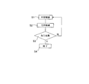
つまり、図4のフローチャートに示すように、先ず、ステップS1にて、CAD/CAMメーカ10は外部機器(=CAD/CAM11)により工作機械の動かし方を記述した加工プログラムを作成し、次いで、ステップS2にて、工作機械メーカ20は外部機器にて作成された加工プログラムを工作機械21にインストールする。
つまり、図4のフローチャートに示すように、先ず、ステップS1にて、CAD/CAMメーカ10は外部機器(=CAD/CAM11)により工作機械の動かし方を記述した加工プログラムを作成し、次いで、ステップS2にて、工作機械メーカ20は外部機器にて作成された加工プログラムを工作機械21にインストールする。
引き続き、ステップS3にて、工作機械ユーザ30は工作機械21により上記加工プログラム従い工具を動かし所要の形状にワーク(=被加工物31)を加工して、実際のワーク形状についての加工結果が、目標とするワーク形状に対して許容値を満たすか否か判定する。
そして、許容値を満たす場合には、ステップS4にて終了となる。一方、許容値を満たさない場合は、許容値を満たすまで、上記パラメータの修正値が工作機械ユーザ30からCAD/CAMメーカ10へフィードバックされることが繰り返されていた。
そして、許容値を満たす場合には、ステップS4にて終了となる。一方、許容値を満たさない場合は、許容値を満たすまで、上記パラメータの修正値が工作機械ユーザ30からCAD/CAMメーカ10へフィードバックされることが繰り返されていた。
このように、パラメータの修正値が外部機器にフィードバックされることが繰り返され、実加工までに行う時間と費用が大きくなっており、これらを最小にしたいという要請があった。
言い換えると、都度ワークが変わるジョブショップあるいは多品種少量生産の工作機械ユーザにとって、上記パラメータの修正値が外部機器にフィードバックすることの繰り返しを無くことが最善であるが、そのような繰り返しをなくせないまでも、フィードバックの繰り返し回数を減らし、早く加工に取り掛かりたいという要請があったのである。
言い換えると、都度ワークが変わるジョブショップあるいは多品種少量生産の工作機械ユーザにとって、上記パラメータの修正値が外部機器にフィードバックすることの繰り返しを無くことが最善であるが、そのような繰り返しをなくせないまでも、フィードバックの繰り返し回数を減らし、早く加工に取り掛かりたいという要請があったのである。
なお、特許文献1では、NC工作機械における工具の移動経路及び切削条件などのデータからなるツールパスデータ、並びにその他の加工に関係するデータから構成される加工関連情報を自動的に生成する加工関連情報生成装置、並びにこの加工関連情報生成装置を備えた数値制御装置が開発されている。
CAD/CAMメーカ10側において、加工プログラム作成時に実際に加工する工具の詳細情報等があればさらに正確な加工プログラムを事前に演算し、作成することが可能である。例えば、工具長や工具径について正確に計測する装置を用いれば、正確で再現性の高い工具測定結果をフィードバックすることが出来るので、その情報を外部機器と共有することで加工プログラム作成時間が短縮することが可能となる。更には、オペレータ(プログラマ)の入力ミスも防げる利点もある。
本発明は、上記従来技術に鑑みてなされたものであり、工作機械の動かし方を記述した加工プログラムに対して、工作機械側の実態を反映したパラメータを入力することが可能なインターフェースシステムを提供するにある。
上記課題を解決する本発明の請求項1に係る工作機械のインターフェースシステムは、工作機械に関係するパラメータとして予めデフォルト値を入力して、前記工作機械の動かし方を記述した加工プログラムを作成する加工プログラム作成用コンピュータと、前記加工プログラムに従い工具を動かして所定の形状にワークを加工する工作機械と、前記工作機械の実態に基づいて前記加工プログラムにおける前記工作機械に関するパラメータについての補正値を自動的に検出する検出手段と、前記検出手段により検出された補正値を前記コンピュータに認識できる形式として、前記コンピュータへ引き渡すインターフェース部とからなり、前記コンピュータは前記インターフェース部から引き渡された前記補正値に基づき前記工作機械に関係するパラメータの実態を反映するべく前記デフォルト値を補正する機能を有することを特徴とする。
上記課題を解決する本発明の請求項2に係る工作機械のインターフェースシステムは、工作機械に関係するパラメータとして予めデフォルト値を入力して作成され、工作機械の動かし方を記述した加工プログラムに従い工具を動かして所定の形状にワークを加工する工作機械と、前記工作機械の実態に基づいて前記加工プログラムにおける前記工作機械に関するパラメータについての補正値を自動的に検出する検出手段と、前記検出手段により検出された補正値を、前記加工プログラムを作成した加工プログラム作成用コンピュータに認識できる形式として、前記コンピュータへ引き渡すインターフェース部とからなる、ことを特徴とする。
上記課題を解決する本発明の請求項3に係る工作機械のインターフェースシステムは、請求項1又は2において、前記工作機械に関係するパラメータとしては、前記工作機械の本体に関係するパラメータ、前記工作機械の工具に関係するパラメータ及び前記工作機械の本体又は工具の制約に関係するパラメータが使用されることを特徴とする。
上記課題を解決する本発明の請求項4に係る工作機械のインターフェースシステムは、請求項1又は2において、前記工作機械により加工された被加工物の実際のワーク形状と目標とするワーク形状との比較により求めた前記パラメータの修正値に基づき前記デフォルト値を修正する機能を前記コンピュータは有することを特徴とする。
本発明の請求項1に係る工作機械のインターフェースシステムは、工作機械に関係するパラメータを工作機械の実態を示す補正値として検出手段により自動的に検出し、検出された補正値をインターフェース部により加工プログラム用コンピュータに認識できる形式として、加工プログラム用コンピュータへ引き渡すので、加工プログラム用コンピュータは、工作機械の実態を反映したパラメータを入力して加工プログラムを作成することが出来るという効果を奏する。
本発明の請求項2に係る工作機械のインターフェースシステムは、工作機械に関係するパラメータを工作機械の実態を示す補正値として検出手段により自動的に検出し、検出された補正値をインターフェース部により加工プログラム用コンピュータに認識できる形式として加工プログラム用コンピュータへ引き渡すことが出来るという効果を奏する。
本発明の請求項3に係る工作機械のインターフェースシステムは、本発明の請求項1又は2と同様な効果を奏する他、工作機械に関係するパラメータとして、工作機械の本体に関係するパラメータ、工作機械の工具に関係するパラメータ及び工作機械の本体や工具の制約に関係するパラメータに関して、工作機械の実態を反映したパラメータを入力して加工プログラムを作成することが出来るという効果を奏する。
本発明の請求項4に係る工作機械のインターフェースシステムは、本発明の請求項1又は2と同様な効果を奏する他、工作機械により加工された被加工物の実際のワーク形状と目標とするワーク形状との比較により求めた工作機械に関係するパラメータの修正値に基づき、加工プログラム用コンピュータがデフォルト値を修正することが出来るという効果を奏する。
以下、本発明について、図面示す実施例を参照して詳細に説明する。
本発明の一実施例を図1に示す。
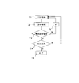
図1は、本発明の一実施例に係る工作機械のインターフェースシステムを利用したCAD/CAMメーカ10、機械加工メーカ20及び機械加工ユーザ30の関係を示すものである。
CAD/CAMメーカ10においては、図1に示すように、CAD/CAM11により、工作機械の動かし方を記述した加工プログラムが作成されている。
図1は、本発明の一実施例に係る工作機械のインターフェースシステムを利用したCAD/CAMメーカ10、機械加工メーカ20及び機械加工ユーザ30の関係を示すものである。
CAD/CAMメーカ10においては、図1に示すように、CAD/CAM11により、工作機械の動かし方を記述した加工プログラムが作成されている。
但し、工作機械の動かし方を記述した加工プログラム中の工作機械に関係するパラメータとしては、理想的な値が予めデフォルト値として入力される。このデフォルト値は、工作機械側の実態を反映していない。
また、工作機械メーカ20においては、図1に示すように、CAD/CAM11により作成された加工プログラムという情報が工作機械21にインストールされ、加工プログラムに従い工具を動かし所要の形状にワークを加工する工作機械21が作製されている。
また、工作機械メーカ20においては、図1に示すように、CAD/CAM11により作成された加工プログラムという情報が工作機械21にインストールされ、加工プログラムに従い工具を動かし所要の形状にワークを加工する工作機械21が作製されている。
ここで、加工プログラム中の工作機械21に関係するパラメータとしては、工作機械本体に関係するパラメータ22、工具に関係するパラメータ23及び工作機械本体と工具と制約に関係するパラメータ24の三種類がある。
工作機械本体に関係するパラメータ22の特徴としては、同じ工作機械であっても機体によりパラメータが異なる点、同じ機体でも経年変化によりパラメータが変化する点が挙げられる。工作機械としては、例えば、歯車研削盤、5面加工機、横中ぐり盤等がある。工作機械本体に関係するパラメータ22としては、一般には、工作機械の緒元が挙げられる。機種毎のパラメータとしては、3軸機MCや5軸機MCの場合は、工具情報、ワーク情報、測定情報、時定数、軸情報等がある。
工作機械本体に関係するパラメータ22の特徴としては、同じ工作機械であっても機体によりパラメータが異なる点、同じ機体でも経年変化によりパラメータが変化する点が挙げられる。工作機械としては、例えば、歯車研削盤、5面加工機、横中ぐり盤等がある。工作機械本体に関係するパラメータ22としては、一般には、工作機械の緒元が挙げられる。機種毎のパラメータとしては、3軸機MCや5軸機MCの場合は、工具情報、ワーク情報、測定情報、時定数、軸情報等がある。
工具に関係するパラメータ23の特徴としては、加工の進展に応じて工具を変えながら加工を進める(1つの工具で全ての加工をする訳ではない)点、同じ工具でも機械への取付け状態、経年変化によりパラメータが異なる点が挙げられる。工具に関係するパラメータ23としては、各種工具についての工具径、工具長等が代表的であり、何れも経年変化後の値を含む。
工作機械本体と工具と制約に関係するパラメータ24の特徴としては、工作機械や工具の制約(所与の位置・姿勢、工具の突き出し量では機械や工具の剛性が足りずヒビる等)から所要の形状を実現するために必要な工具軌跡が実現できない場合ある点が挙げられる。工作機械本体と工具と制約に関係するパラメータ24としては、工作機械や工具の干渉を回避するための情報がある。
工作機械本体と工具と制約に関係するパラメータ24の特徴としては、工作機械や工具の制約(所与の位置・姿勢、工具の突き出し量では機械や工具の剛性が足りずヒビる等)から所要の形状を実現するために必要な工具軌跡が実現できない場合ある点が挙げられる。工作機械本体と工具と制約に関係するパラメータ24としては、工作機械や工具の干渉を回避するための情報がある。
本実施例では、工作機械メーカ20において、工作機械21の実態に基づいて、加工プログラム中の工作機械21に関係するパラメータについての補正値を自動的に検出する検出手段40を設ける。
例えば、検出手段40として、工作機械21の工具を光学的に撮像して工具長や工具径を計測する工具計測装置を使用すると、工具径や工具長に関係するパラメータについての補正値を検出することができる。
例えば、検出手段40として、工作機械21の工具を光学的に撮像して工具長や工具径を計測する工具計測装置を使用すると、工具径や工具長に関係するパラメータについての補正値を検出することができる。
検出手段40が補正値として、工具径や工具長の長さをそのまま検出した場合には、CAD/CAM11では、デフォルト値を検出された工具径や工具長の長さに置き換えることになる。また、補正値として、検出された工具径や工具長の長さとデフォルト値との偏差を用いるときは、CAD/CAM11では、デフォルト値に偏差を加算(減算)すれば良い。
また、検出手段40は、工作機械メーカ20内のデータベースに保管されている又は工作機械21の記憶装置に予め記憶されている各工作機械21に固有なパラメータ22,23,24を補正値として検出することも可能である。
また、検出手段40は、工作機械メーカ20内のデータベースに保管されている又は工作機械21の記憶装置に予め記憶されている各工作機械21に固有なパラメータ22,23,24を補正値として検出することも可能である。
なお、検出手段40は、加工プログラム中にパラメータとして入力されていたデフォルト値と上記補正値とを比較して、補正する必要があるか否か判定する機能を具備すると良い。偶然ではあるが、理想値として入力されたデフォルト値が、工作機械21の実態を反映していることも有り得るからである。
検出手段40により検出された補正値は、インターフェース部50により、CAD/CAM11に認識できる形式として、CAD/CAM11に引き渡される。インターフェース部50としては、規格により情報を伝達する箇所が規定されている入出力ポートを使用できる。インターフェース部50に関係する規格は、CAD/CAMメーカ10と工作機械メーカ20で共通化しておく必要がある。インターフェース部50は、有線ネットワークを利用するものに限らず、無線ネットワークを利用するものでも良い。
検出手段40により検出された補正値は、インターフェース部50により、CAD/CAM11に認識できる形式として、CAD/CAM11に引き渡される。インターフェース部50としては、規格により情報を伝達する箇所が規定されている入出力ポートを使用できる。インターフェース部50に関係する規格は、CAD/CAMメーカ10と工作機械メーカ20で共通化しておく必要がある。インターフェース部50は、有線ネットワークを利用するものに限らず、無線ネットワークを利用するものでも良い。
CAD/CAM11は、インターフェース部50により受け渡された補正値に基づいて、工作機械21の実態を反映するべく、デフォルト値をこれら補正値により補正する補正機能が付加され、補正されたパラメータにより加工プログラムを作成する。
補正機能としては、前述した例の通り、補正値として、工具径や工具長の長さをそのまま検出した場合には、デフォルト値を検出された工具径や工具長の長さに置き換え、また、補正値として、検出された工具径や工具長の長さとデフォルト値との偏差を用いるときは、デフォルト値に偏差を加算する。
補正機能としては、前述した例の通り、補正値として、工具径や工具長の長さをそのまま検出した場合には、デフォルト値を検出された工具径や工具長の長さに置き換え、また、補正値として、検出された工具径や工具長の長さとデフォルト値との偏差を用いるときは、デフォルト値に偏差を加算する。
一方、工作機械ユーザ30においては、図1に示すように、工作機械メーカ20により作製された工作機械により被加工物31に対して加工という行為を行い、加工された被加工物31の寸法を計測した結果等により実際のワーク形状に関係する情報を取得し、目標とするワーク形状と実際のワーク形状とを作業者32が比較して、上記パラメータの修正値を検討する。
そして、作業者32により、上記パラメータの修正値が求められると、パラメータの修正値という情報として、CAD/CAMメーカ10へフィードバックされ、その修正値に基づき加工プログラム中のパラメータが修正される。
そして、作業者32により、上記パラメータの修正値が求められると、パラメータの修正値という情報として、CAD/CAMメーカ10へフィードバックされ、その修正値に基づき加工プログラム中のパラメータが修正される。
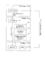
本実施例に係る工作機械のインターフェースシステムについての作業手順を図2のフローチャートを参照して説明する。
先ず、ステップT1にて、CAD/CAMメーカ10は外部機器(=CAD/CAM11)により工作機械の動かし方を記述した加工プログラムを作成し、次いで、ステップT2にて、工作機械メーカ20は外部機器にて作成された加工プログラムを工作機械21にインストールする。
先ず、ステップT1にて、CAD/CAMメーカ10は外部機器(=CAD/CAM11)により工作機械の動かし方を記述した加工プログラムを作成し、次いで、ステップT2にて、工作機械メーカ20は外部機器にて作成された加工プログラムを工作機械21にインストールする。
更に、ステップT3にて、工作機械メーカ20は外部機器により作成された加工プログラム中にデフォルト値として入力されていた値(事前設定情報)が検出手段40により検出された補正値により補正する必要があるか否か判定する。
ステップT3にて補正する必要があると判定されると、ステップT6にて、検出手段40により検出された補正値がインターフェース部50を介して外部機器へ引き渡される。
ステップT3にて補正する必要があると判定されると、ステップT6にて、検出手段40により検出された補正値がインターフェース部50を介して外部機器へ引き渡される。
一方、ステップT3にて補正する必要がないと判定されると、ステップT4にて、工作機械ユーザ30は工作機械21により上記加工プログラムに従い工具を動かし所要の形状にワーク(=被加工物31)を加工し、実際のワーク形状についての加工結果が、目標とするワーク形状に対して許容値を満たすか否か判定する。
そして、許容値を満たす場合には、ステップT5にて終了となる。一方、許容値を満たさない場合は、上記パラメータの修正値が工作機械ユーザ30からCAD/CAMメーカ10へフィードバックされる。
そして、許容値を満たす場合には、ステップT5にて終了となる。一方、許容値を満たさない場合は、上記パラメータの修正値が工作機械ユーザ30からCAD/CAMメーカ10へフィードバックされる。
このように、工作機械に関係するパラメータについての補正値が検出手段40により検出され、インターフェース部50を介して外部機器へ引き渡されるので、実際に加工を行って求めたパラメータの修正値が外部機器にフィードバックされる回数が低減し、実加工までに行う時間と費用を削減できるという効果を奏する。
つまり、上記パラメータの修正値が外部機器にフィードバックすることを無くすことが最善であるが、そうでなくてもフィードバックの繰り返し回数を減らし、早く加工に取り掛かりたいという要請を満たすことが可能となった。
更に、上述した実施例によれば、以下の効果も奏する。
つまり、上記パラメータの修正値が外部機器にフィードバックすることを無くすことが最善であるが、そうでなくてもフィードバックの繰り返し回数を減らし、早く加工に取り掛かりたいという要請を満たすことが可能となった。
更に、上述した実施例によれば、以下の効果も奏する。
(1)正確な工具形状を事前にCAM/CAM側に情報を渡すことで事前に正確な演算処理が可能となる。CAM/CAMは、演算処理時間を短縮する要求が強い。特に5軸機MCではオフセットが出来ない場合があるので都度再演算が必要となる。
(2)何枚刃の工具かの情報は工作機械側にないので、その情報があればチッピング(欠け)測定が可能となる。1回転で何枚刃があるかは、撮像で確認することが可能である。
(3)軸加工の機能にボールエンドミルの先端を避けて加工するモジュールがあるが、何度傾けて加工するようにCAM/CAMで設定したのか、工作機械側で判れば加工による磨耗個所がわかるため、磨耗測定計測指示が自動化される。
(4)5軸機MCにおいて2軸回転軸の直行座標が工作機械側からCAM/CAMに情報として引き渡されれば加工プログラム上で補正可能である。
(5)CAM/CAM側のモデル(コンピュータ内の形状)において測定点を設定しておき、座標軸を工作機械側に伝達することで、指定ポイントの測定を自動的に実施し、許容値を決めれば良否の判定が工作機械上で可能となる。
(6)工作機械のパラメータをCAM/CAM側に情報として伝えることで正確な加工時間の予測が可能である。
本発明は、工作機械と周辺機器とのインターフェースを行うシステムとして広く産業上利用可能なものである。
10 CAM/CAMメーカ
11 CAM/CAM
20 工作機械メーカ
21 工作機械
30 工作機械ユーザ
40 検出手段
50 インターフェース部
11 CAM/CAM
20 工作機械メーカ
21 工作機械
30 工作機械ユーザ
40 検出手段
50 インターフェース部
Claims (4)
- 工作機械に関するパラメータとして予めデフォルト値を入力して、前記工作機械の動かし方を記述した加工プログラムを作成する加工プログラム作成用コンピュータと、
前記加工プログラムに従い工具を動かして所定の形状にワークを加工する工作機械と、
前記工作機械の実態に基づいて前記加工プログラムにおける前記工作機械に関するパラメータについての補正値を自動的に検出する検出手段と、
前記検出手段により検出された補正値を前記コンピュータに認識できる形式として、前記コンピュータへ引き渡すインターフェース部とからなり、
前記コンピュータは前記インターフェース部から引き渡された前記補正値に基づき前記工作機械に関するパラメータの実態を反映するべく前記デフォルト値を補正する機能を有することを特徴とする工作機械のインターフェースシステム。 - 工作機械に関するパラメータとして予めデフォルト値を入力して作成され、工作機械の動かし方を記述した加工プログラムに従い工具を動かして所定の形状にワークを加工する工作機械と、
前記工作機械の実態に基づいて前記加工プログラムにおける前記工作機械に関するパラメータについての補正値を自動的に検出する検出手段と、
前記検出手段により検出された補正値を、前記加工プログラムを作成した加工プログラム作成用コンピュータに認識できる形式として、前記コンピュータへ引き渡すインターフェース部とからなる、
ことを特徴とする工作機械のインターフェースシステム。 - 請求項1又は2において、前記工作機械に関するパラメータとしては、前記工作機械の本体に関するパラメータ、前記工作機械の工具に関するパラメータ及び前記工作機械の本体又は工具の制約に関するパラメータが使用されることを特徴とする工作機械のインターフェースシステム。
- 請求項1又は2において、前記工作機械により加工された被加工物の実際のワーク形状と目標とするワーク形状との比較により求めた前記パラメータの修正値に基づき前記デフォルト値を修正する機能を前記コンピュータは有することを特徴とする工作機械のインターフェースシステム。
Priority Applications (3)
| Application Number | Priority Date | Filing Date | Title |
|---|---|---|---|
| US14/432,622 US20150261204A1 (en) | 2012-11-14 | 2013-06-26 | Interface system of industrial machine |
| EP13856036.2A EP2898984A4 (en) | 2012-11-14 | 2013-06-26 | INDUSTRIAL MACHINE INTERFACE SYSTEM |
| CN201380049582.6A CN104661793A (zh) | 2012-11-14 | 2013-06-26 | 机床的接口系统 |
Applications Claiming Priority (2)
| Application Number | Priority Date | Filing Date | Title |
|---|---|---|---|
| JP2012249975A JP5984630B2 (ja) | 2012-11-14 | 2012-11-14 | 工作機械のインターフェースシステム |
| JP2012-249975 | 2012-11-14 |
Publications (1)
| Publication Number | Publication Date |
|---|---|
| WO2014076996A1 true WO2014076996A1 (ja) | 2014-05-22 |
Family
ID=50730922
Family Applications (1)
| Application Number | Title | Priority Date | Filing Date |
|---|---|---|---|
| PCT/JP2013/067447 WO2014076996A1 (ja) | 2012-11-14 | 2013-06-26 | 工作機械のインターフェースシステム |
Country Status (5)
| Country | Link |
|---|---|
| US (1) | US20150261204A1 (ja) |
| EP (1) | EP2898984A4 (ja) |
| JP (1) | JP5984630B2 (ja) |
| CN (1) | CN104661793A (ja) |
| WO (1) | WO2014076996A1 (ja) |
Families Citing this family (9)
| Publication number | Priority date | Publication date | Assignee | Title |
|---|---|---|---|---|
| CN106808310A (zh) * | 2015-11-30 | 2017-06-09 | 湖南衡泰机械科技有限公司 | Cnc工具机的调整控制系统 |
| US10642251B2 (en) | 2016-04-14 | 2020-05-05 | David E Platts | Subtractive machining work center |
| EP3285125A1 (de) * | 2016-08-17 | 2018-02-21 | Siemens Aktiengesellschaft | Erzeugung optimierter bahndaten für eine werkzeugmaschine |
| US10401803B2 (en) * | 2016-09-26 | 2019-09-03 | General Electric Company | Apparatus and method for computer code adjustments in an industrial machine |
| WO2018101109A1 (ja) * | 2016-12-02 | 2018-06-07 | 三菱電機株式会社 | 複合加工システムおよび複合加工方法 |
| CA3062081A1 (en) * | 2017-06-23 | 2018-12-27 | Flow International Corporation | Autonomous modification of waterjet cutting systems |
| JP6813521B2 (ja) * | 2018-02-08 | 2021-01-13 | ファナック株式会社 | 温度計測装置 |
| JP7088872B2 (ja) * | 2019-04-03 | 2022-06-21 | ファナック株式会社 | 評価用ワークおよび加工プログラム |
| JP2022143423A (ja) * | 2021-03-17 | 2022-10-03 | 株式会社リコー | 診断装置、診断システム、診断方法及び診断プログラム |
Citations (2)
| Publication number | Priority date | Publication date | Assignee | Title |
|---|---|---|---|---|
| JPH079303A (ja) * | 1993-06-23 | 1995-01-13 | Kobe Steel Ltd | 工作機械の機械パラメータの補正方法及びその装置 |
| JP2002189510A (ja) | 2000-12-22 | 2002-07-05 | Mori Seiki Co Ltd | 加工関連情報生成装置、及びこれを備えた数値制御装置 |
Family Cites Families (16)
| Publication number | Priority date | Publication date | Assignee | Title |
|---|---|---|---|---|
| JPS5969248A (ja) * | 1982-10-12 | 1984-04-19 | Okuma Mach Works Ltd | 工具径自動計測補正方法 |
| JPS6332608A (ja) * | 1986-07-26 | 1988-02-12 | Fanuc Ltd | 数値制御装置 |
| CA2082708C (en) * | 1991-12-02 | 2004-01-13 | James Edward Randolph Jr. | Tool point compensation for hardware displacement and inclination |
| JPH05282021A (ja) * | 1992-03-31 | 1993-10-29 | Fanuc Ltd | Nc工作機械の加工条件生成方式 |
| JP3509964B2 (ja) * | 1994-11-22 | 2004-03-22 | 株式会社アマダ | Nc加工機用稼働記録方法および記録装置 |
| EP0881034B1 (en) * | 1996-11-07 | 2009-01-07 | Kabushiki Kaisha Mori Seiki Seisakusho | Method and device for analyzing nc program for nc machining |
| JP3593302B2 (ja) * | 1999-06-15 | 2004-11-24 | 株式会社ミツトヨ | 画像測定装置及び方法 |
| US6671572B1 (en) * | 2002-07-09 | 2003-12-30 | Agile Technology Partners, Llc | Method and computer program for automated design and manufacture of custom workholding fixtures requiring machining of substantially unique mounting geometries |
| WO2006016420A1 (ja) * | 2004-08-12 | 2006-02-16 | Makino Milling Machine Co., Ltd. | ワークを加工する加工方法 |
| US7583852B2 (en) * | 2004-10-26 | 2009-09-01 | Mitutoyo Corporation | Method of filtering an image for high precision machine vision metrology |
| US7090561B2 (en) * | 2004-12-07 | 2006-08-15 | General Electric Company | Method and apparatus for pivot point determination and machine tool adjustment |
| US8581162B2 (en) * | 2009-12-08 | 2013-11-12 | Mitutoyo Corporation | Weighting surface fit points based on focus peak uncertainty |
| CN101968641B (zh) * | 2010-07-08 | 2012-06-13 | 西华大学 | 一种机床xy平面误差修正系统 |
| CN102004466B (zh) * | 2010-10-25 | 2012-05-09 | 武汉华中数控股份有限公司 | 一种基于指令序列分析的数控机床加工动态误差补偿方法 |
| US8696271B2 (en) * | 2010-11-12 | 2014-04-15 | Cory Dickey | Fastening nut and tool bit holding system |
| CN102501136B (zh) * | 2011-10-10 | 2013-09-18 | 华中科技大学 | 一种数控机床在机检测测头及检测系统 |
-
2012
- 2012-11-14 JP JP2012249975A patent/JP5984630B2/ja not_active Expired - Fee Related
-
2013
- 2013-06-26 WO PCT/JP2013/067447 patent/WO2014076996A1/ja active Application Filing
- 2013-06-26 CN CN201380049582.6A patent/CN104661793A/zh active Pending
- 2013-06-26 EP EP13856036.2A patent/EP2898984A4/en not_active Withdrawn
- 2013-06-26 US US14/432,622 patent/US20150261204A1/en not_active Abandoned
Patent Citations (2)
| Publication number | Priority date | Publication date | Assignee | Title |
|---|---|---|---|---|
| JPH079303A (ja) * | 1993-06-23 | 1995-01-13 | Kobe Steel Ltd | 工作機械の機械パラメータの補正方法及びその装置 |
| JP2002189510A (ja) | 2000-12-22 | 2002-07-05 | Mori Seiki Co Ltd | 加工関連情報生成装置、及びこれを備えた数値制御装置 |
Non-Patent Citations (1)
| Title |
|---|
| See also references of EP2898984A4 |
Also Published As
| Publication number | Publication date |
|---|---|
| JP2014097543A (ja) | 2014-05-29 |
| EP2898984A4 (en) | 2015-11-04 |
| CN104661793A (zh) | 2015-05-27 |
| JP5984630B2 (ja) | 2016-09-06 |
| EP2898984A1 (en) | 2015-07-29 |
| US20150261204A1 (en) | 2015-09-17 |
Similar Documents
| Publication | Publication Date | Title |
|---|---|---|
| JP5984630B2 (ja) | 工作機械のインターフェースシステム | |
| US9895810B2 (en) | Cooperation system having machine tool and robot | |
| US8090557B2 (en) | Quality assurance method when operating an industrial machine | |
| CN103460151B (zh) | 用于借助数字控制的工件加工装置加工工件的方法以及工件加工装置 | |
| US10112304B2 (en) | Robot programming apparatus for teaching machining operation to robot | |
| US9205525B2 (en) | System and method for offsetting measurement of machine tool | |
| JPWO2013038529A1 (ja) | 加工誤差算出装置、加工誤差算出方法、加工制御装置および加工制御方法 | |
| JP2010052067A (ja) | 自動仕上げ装置とその制御方法 | |
| US20160103447A1 (en) | Numerical control unit with the option of modifying the sub-program | |
| CN109358567B (zh) | 数控机床刀具路径补偿及加工的方法 | |
| KR20220044506A (ko) | 정밀 지그 연삭 공정 중 가공오차 보정 시스템 및 방법 | |
| US20130041498A1 (en) | Numerical control method and device thereof | |
| CN101224562A (zh) | 用于控制可移动工具的方法和设备、输入装置和机械工具 | |
| JP6088190B2 (ja) | 加工システム、及びその加工方法 | |
| KR101960171B1 (ko) | 5축 가공장치의 피봇 교정 방법 | |
| US20140228996A1 (en) | System and method for virtually calibrating computer numeric controlled machine axes | |
| JP2007257606A (ja) | ツールの加工位置決め誤差補正方法 | |
| JP6166300B2 (ja) | 工具と被加工物の干渉チェックが可能な数値制御装置 | |
| CN105911959B (zh) | 具有车齿加工的工具修正功能的数值控制装置 | |
| KR101809244B1 (ko) | 보정지그를 이용한 5축 치아가공기 원점 보정방법 | |
| WO2015063912A1 (ja) | 位置決め精度の設定方法、位置決め精度設定装置および位置決め精度の設定プログラム | |
| JP2006305691A (ja) | Ncプログラム作成方法 | |
| JP2016038674A (ja) | 工作機械の補正値演算方法及び補正値演算プログラム | |
| KR102698345B1 (ko) | 공작 기계의 제어 방법 및 제어 시스템 | |
| JP2013059841A (ja) | 加工誤差算出装置、加工誤差算出方法、加工制御装置および加工制御方法 |
Legal Events
| Date | Code | Title | Description |
|---|---|---|---|
| 121 | Ep: the epo has been informed by wipo that ep was designated in this application |
Ref document number: 13856036 Country of ref document: EP Kind code of ref document: A1 |
|
| WWE | Wipo information: entry into national phase |
Ref document number: 14432622 Country of ref document: US |
|
| WWE | Wipo information: entry into national phase |
Ref document number: 2013856036 Country of ref document: EP |
|
| NENP | Non-entry into the national phase |
Ref country code: DE |