WO2014073048A1 - パワーステアリング装置及びその作動油供給方法 - Google Patents
パワーステアリング装置及びその作動油供給方法 Download PDFInfo
- Publication number
- WO2014073048A1 WO2014073048A1 PCT/JP2012/078809 JP2012078809W WO2014073048A1 WO 2014073048 A1 WO2014073048 A1 WO 2014073048A1 JP 2012078809 W JP2012078809 W JP 2012078809W WO 2014073048 A1 WO2014073048 A1 WO 2014073048A1
- Authority
- WO
- WIPO (PCT)
- Prior art keywords
- hydraulic pump
- hydraulic
- hydraulic oil
- flow rate
- vehicle
- Prior art date
- Legal status (The legal status is an assumption and is not a legal conclusion. Google has not performed a legal analysis and makes no representation as to the accuracy of the status listed.)
- Ceased
Links
Images





Classifications
-
- B—PERFORMING OPERATIONS; TRANSPORTING
- B62—LAND VEHICLES FOR TRAVELLING OTHERWISE THAN ON RAILS
- B62D—MOTOR VEHICLES; TRAILERS
- B62D5/00—Power-assisted or power-driven steering
- B62D5/06—Power-assisted or power-driven steering fluid, i.e. using a pressurised fluid for most or all the force required for steering a vehicle
- B62D5/065—Power-assisted or power-driven steering fluid, i.e. using a pressurised fluid for most or all the force required for steering a vehicle characterised by specially adapted means for varying pressurised fluid supply based on need, e.g. on-demand, variable assist
Definitions
- the present invention relates to a power steering apparatus and a hydraulic oil supply method thereof.
- an object of the present invention is to provide a power steering device capable of improving fuel consumption.
- the power steering apparatus operates on the first hydraulic pump driven by an electric motor, which supplies hydraulic oil to the steering force assist mechanism that assists the steering force by hydraulic pressure, and the steering force assist mechanism.
- An engine-driven second hydraulic pump that supplies oil, a hydraulic oil supplied by the first hydraulic pump, and a control device that controls two flow rates of the hydraulic oil supplied by the second hydraulic pump.
- the control device controls the flow rate so that the hydraulic oil supplied by the first hydraulic pump is supplemented by the hydraulic oil supplied by the second hydraulic pump according to the driving state of the vehicle.
- the hydraulic fluid supply method for the power steering apparatus includes a first hydraulic pump driven by an electric motor and an engine drive that supplies hydraulic fluid to a steering force assist mechanism that assists the steering force of the vehicle by hydraulic pressure.
- the control unit controls the second hydraulic pump
- the control unit supplements the hydraulic oil supplied by the first hydraulic pump with the hydraulic oil supplied by the second hydraulic pump according to the driving state of the vehicle.
- the flow rate of the hydraulic oil to the steering force assist mechanism is controlled.
- the hydraulic fluid supplied from the hydraulic pump driven by the electric motor is supplemented with the hydraulic fluid supplied from the hydraulic pump driven by the engine, thereby improving the fuel consumption. be able to.
- Schematic which shows an example of a power steering apparatus.
- Explanatory drawing explaining the required flow volume required for assistance of steering force in a steering force assistance mechanism.
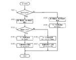
- the flowchart which shows the processing content of hydraulic oil supply control.
- Explanatory drawing explaining the rotational speed control of the electric motor which drives a 1st hydraulic pump.
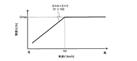
- Explanatory drawing explaining the opening degree control of a flow control valve.
- Explanatory drawing explaining the rotational speed control of the electric motor at the time of 2nd hydraulic pump abnormality.
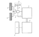
- Explanatory drawing which shows the example of application in a front biaxial vehicle. Schematic which shows another aspect of the hydraulic-oil supply mechanism of FIG.
- FIG. 1 shows an example of a power steering device mounted on a vehicle.
- the power steering device includes a hydraulic oil supply mechanism 10, a steering force generation mechanism 12, a steering force assist mechanism 14, and a control unit 16.
- the hydraulic oil supply mechanism 10 supplies the hydraulic oil whose flow rate is controlled by the control unit 16 to the steering force auxiliary mechanism 14, and the steering force auxiliary mechanism 14 uses the hydraulic pressure of the hydraulic oil, The steering force generated by the steering force generation mechanism 12 is assisted.
- the hydraulic oil supply mechanism 10 includes a first hydraulic pump 20 driven by the electric motor 18 and a second hydraulic pump 24 driven by the engine 22.
- the first hydraulic pump 20 supplies hydraulic oil from the oil tank 26 to the steering force assist mechanism 14 via the first supply pipe 28.
- the second hydraulic pump 24 supplies hydraulic oil from the oil tank 30 to the steering force assisting mechanism 14 via the second supply pipe 34 connected to the first supply pipe 28 at the connection portion 32.
- the hydraulic oil supplied to the steering force assisting mechanism 14 returns to the oil tank 26 and the oil tank 30 via the first return pipe 36 and the second return pipe 40 branched by the branch portion 38, respectively.
- the oil tank 26 and the oil tank 30 are connected by a communication pipe 42 so that hydraulic oil is not unevenly distributed in one oil tank.
- a first electromagnetic valve 46 capable of shutting off the hydraulic oil from the second hydraulic pump 24 is provided between the connection portion 32 and the flow restriction valve 44.
- a hydraulic sensor 48 that outputs a signal corresponding to the hydraulic pressure in the second supply pipe 34 is provided on the second hydraulic pump 24 side of the first electromagnetic valve 46.
- a second electromagnetic valve 50 is provided between the branch portion 38 and the flow rate control valve 44 in the second return pipe 40 so that the hydraulic oil returning from the steering force assist mechanism 14 can be shut off by closing the valve.
- the steering force generation mechanism 12 includes a steering wheel 52 for a driver to rotate, a steering shaft 54 coupled to the steering wheel 52, a gear box 56 including a pinion gear and a rack gear (not shown), And an output shaft 58 for transmitting the output of the gear box 56.
- the rotational force of the steering wheel 52 rotates the pinion gear of the gear box 56 via the steering shaft 54 and causes the rack gear meshing with the pinion gear to perform linear motion. Then, this linear motion is transmitted from the output shaft 58 to a knuckle (not shown) of the wheel 60 via, for example, a knuckle arm (not shown).
- the steering force generation mechanism 12 generates a steering force for steering the wheel 60.
- a tie rod arm (not shown) is connected between the knuckle of the wheel 60 and a knuckle (not shown) on the opposite side, and the steering force for the wheel 60 is transmitted to the opposite wheel via the tie rod arm. Also communicated.
- the steering force assist mechanism 14 includes a switching valve 62 and a power cylinder 64.
- the switching valve 62 includes three ports to which the first supply pipe 28 and the first return pipe 40 are selectively connected, that is, a neutral port 62N, a right turning port 62R, and a left turning port 62L.
- the switching valve 62 is configured so that the linear motion generated in the gear box 56 is transmitted via an interlocking member 62a that interlocks with the output shaft 58 or a rack gear.
- the switching valve 62 is driven by a linear motion transmitted from the gear box 56 via the interlocking member 62a, thereby switching the port connecting the first supply pipe 28 and the first return pipe 40.
- the switching valve 62 When the driver holds the steering wheel 52 in the neutral position, the switching valve 62 is fixed to the neutral port 62N. When the driver rotates the steering wheel 52 to the right, the switching valve 62 is switched to the right steering port 62R by being driven by the interlocking member 62a. On the other hand, when the driver rotates the steering wheel 52 counterclockwise, the switching valve 62 is driven by the interlocking member 62a and switches to the left steering port 62L.
- the power cylinder 64 includes a piston 64d that divides the inside of the cylinder tube 64a into a first cylinder chamber 64b and a second cylinder chamber 64c, and a piston rod 64e that is integrated with the piston 64d and moves within the cylinder tube 64a.
- the oil passage 66 communicating with the first cylinder chamber 64b and the oil passage 68 communicating with the second cylinder chamber 64c are connected to the port switched by the switching valve 28.
- the piston rod 64e is connected to the output shaft 58.
- the switching valve 62 When the driver holds the steering wheel 52 in the neutral position, the switching valve 62 is fixed to the neutral port 62N, and therefore flows into the neutral port 62N from the first hydraulic pump 20 or the second hydraulic pump 24.
- the hydraulic oil does not flow into the power cylinder 64 but returns to the oil tank 26 or the oil tank 30 via the first return pipe 36 or the second return pipe 40 branched therefrom.
- the switching valve 62 switches to the right steering port 62R, so that the hydraulic oil flows into the right steering port 62R from the first hydraulic pump 20 or the second hydraulic pump 24.
- the piston rod 64 e applies a tensile force to the output shaft 58 to assist the steering force of the wheel 60.
- the steering force is assisted in substantially the same manner as when the steering wheel 52 is rotated clockwise.
- the control unit 16 has a built-in computer and controls the flow rate of hydraulic oil supplied from the hydraulic oil supply mechanism 10 to the steering force assist mechanism 14 in accordance with the driving state of the vehicle, and is output from the hydraulic sensor 48.
- the electric motor 18, the flow control valve 44, the first electromagnetic valve 46, and the second electromagnetic valve 50 are controlled based on input signals such as a hydraulic pressure signal, a vehicle speed signal, and an ignition signal.
- the required flow rate Fneed of the hydraulic oil necessary for assisting the steering force in the steering force assist mechanism 14 gradually decreases as the vehicle speed V increases.
- the flow rate of hydraulic oil discharged from the engine-driven hydraulic pump depends on the rotational speed of the engine, even if the vehicle speed increases, it does not decrease but rather tends to increase. For this reason, the engine-driven hydraulic pump discharges an excess amount of hydraulic oil as the vehicle speed increases, and the engine is performing useless work.
- the hydraulic pump driven by the electric motor can discharge the flow rate corresponding to the required flow rate Fneed by controlling the rotation speed of the electric motor, the ratio of the electric motor doing useless work is small. Therefore, it is conceivable to use a hydraulic pump driven by an electric motor alone to supply all the hydraulic fluid having the required flow rate Fneed. However, since the electric motor increases in size and affects the vehicle weight, fuel consumption can be reduced. It is not necessarily effective.
- two small-capacity hydraulic pumps that is, a first hydraulic pump 20 driven by an electric motor 18 and a first hydraulic pump driven by an engine 22 are compared with a hydraulic pump when an engine-driven hydraulic pump is used alone.
- the hydraulic fluid with the required flow rate Fneed is supplied in combination with the hydraulic pump 24.
- the size of the second hydraulic pump 24 driven by the engine 22 can be reduced to reduce the waste of the engine 22. The work amount is reduced, and the fuel oil supply mechanism 10 as a whole is improved in fuel consumption.
- the specific supply of the first hydraulic pump 20 and the second hydraulic pump 24 is supplied from the first hydraulic pump 20 driven at the upper limit rotational speed at which the electric motor 18 can be stably used, that is, the rated rotational speed Nmax.
- the rated flow rate Fmax of the hydraulic oil is insufficient with respect to the required flow rate Fneed, this shortage (shaded portion in FIG. 2) is hydraulic oil supplied by the second hydraulic pump 24 driven by the engine 22. compensate.
- the rotational speed of the electric motor 18 is controlled so that the discharge amount of the first hydraulic oil pump 20 becomes the required flow rate Fneed.
- the rated flow rate Fmax is a minimum flow rate that assists the steering force so that the vehicle can be steered at a minimum level even when an abnormality occurs in the second hydraulic pump 24.
- FIG. 3 shows the processing content of hydraulic oil supply control that is repeatedly executed at predetermined time ⁇ t in the control unit 16 when the ignition switch is turned on.
- step 101 whether or not the second hydraulic pump 24 is discharging hydraulic oil, that is, whether or not an abnormality has occurred in the second hydraulic pump 24.
- the predetermined pressure Pd is a threshold value that defines whether or not an abnormality has occurred in the second hydraulic pump 24. If the hydraulic pressure P is greater than or equal to the predetermined pressure Pd, it is estimated that the second hydraulic pump 24 is normal, and the process proceeds to step 102 (YES). If the hydraulic pressure P is less than the predetermined pressure Pd, the second It is estimated that an abnormality has occurred in the hydraulic pump 24, and the routine proceeds to step 108 (NO).
- step 102 the first solenoid valve 46 and the second solenoid valve 50 are controlled to maintain the opened state, and the hydraulic oil between the second hydraulic pump 24 and the oil tank 30 and the steering force assist mechanism 14 is controlled. Enable distribution.
- step 103 the magnitude relationship between the vehicle speed V detected from the vehicle speed signal and the predetermined speed Vd is determined.
- the predetermined speed Vd is a vehicle speed when the rated flow rate Fmax and the required flow rate Fneed are equal, as shown in FIG. That is, it is a threshold value that defines whether or not supply of hydraulic oil by the second hydraulic pump 24 is required. If the vehicle speed V is less than the predetermined speed Vd, the routine proceeds to step 104 (YES). On the other hand, when the vehicle speed V is equal to or higher than the predetermined speed Vd, the routine proceeds to step 106 (NO).
- step 104 the electric motor 18 is controlled so that the rotational speed N of the electric motor 18 becomes the rated rotational speed Nmax as shown in FIG.
- A is the pump efficiency of the second hydraulic pump 24, and S is a constant.
- the discharge amount of the first hydraulic pump 20 is brought close to the necessary flow rate Fneed.
- the rotational speed N of the electric motor 18 is maintained at a constant rotational speed Nmin so that the steering force can be assisted at least even when the vehicle is traveling at high speed.
- step 107 the flow rate control valve 44 is controlled so that the opening degree G [%] of the flow rate control valve 44 becomes Gmax (fully open) as shown in FIG.
- step 108 control is performed so that the first electromagnetic valve 46 and the second electromagnetic valve 50 are closed, and the hydraulic oil between the second hydraulic pump 24 and the oil tank 30 and the steering force assist mechanism 14 is controlled. Block distribution. Thereby, the inflow of hydraulic oil from the first supply pipe 28 to the second supply pipe 34 and from the first return pipe 36 to the second return pipe 40 is suppressed.
- step 109 the electric motor 18 is controlled so that the rotational speed N of the electric motor 18 always becomes the rated rotational speed Nmax regardless of the vehicle speed, as shown in FIG. This is to ensure a rated flow rate Fmax that assists the steering force so that the vehicle can be steered at a minimum level by such control.
- two hydraulic pumps having a small capacity compared to a hydraulic pump in the case where an engine-driven hydraulic pump is used alone, that is, a first driven by an electric motor 18 are used.
- 1 hydraulic pump 20 and the second hydraulic pump 24 driven by the engine 22 are used in combination to supply hydraulic oil at a required flow rate Fneed.
- downsizing the second hydraulic pump 24 driven by the engine 22 reduces the wasteful work of the engine 22. Since the amount is reduced, it is possible to improve the fuel consumption of the hydraulic oil supply mechanism 10 as a whole.
- the first hydraulic pump 20 used when an abnormality occurs in the second hydraulic pump 24 is always used even when the second hydraulic pump 24 is normal.
- the frequency of use is extremely high, and it is difficult for the engine 22 to become an extra load.
- a hydraulic pump that is used only in the event of an abnormality is driven by a member that interlocks with the rotation of the wheel. I will let you. For this reason, according to the 1st hydraulic pump 20, a fuel consumption can be improved.
- the vehicle on which the power steering apparatus is mounted may be a front biaxial vehicle having a pair of front and rear front two shafts on the front side and at least one rear shaft on the rear side.
- the steering force generating mechanism 12 is connected to these wheels 60 and wheels.
- Steering force for 60 ' is generated, and the steering force assisting mechanism 14 assists this steering force.
- the driving state of the vehicle in the above-described embodiment is not limited to the vehicle speed, and may be the rotational speed or the steering angle of the steering wheel 52.
- the control unit 16 is operated by the second hydraulic pump 24 so that the vehicle can be steered at a minimum level when an abnormality occurs in the first hydraulic pump 20.
- the steering force may be assisted by oil.
- the hydraulic fluid from the first hydraulic pump 20 can be shut off by closing the connection between the connection portion 32 and the first hydraulic pump 20 in the first supply pipe 28.
- a third electromagnetic valve 70 is provided.
- a hydraulic sensor 72 that outputs a signal corresponding to the hydraulic pressure in the first supply pipe 28 is provided between the first hydraulic pump 20 and the third electromagnetic valve 70.
- a fourth electromagnetic valve 74 is provided between the branch portion 38 and the oil tank 26 so that the hydraulic oil returning from the steering force assisting mechanism 14 can be shut off by closing the valve. Then, in the control unit 16, if the hydraulic pressure P detected from the hydraulic pressure signal is less than the predetermined pressure Pd, it is estimated that an abnormality has occurred in the first hydraulic pump 20. In this case, the control unit 16 controls the third electromagnetic valve 70 and the fourth electromagnetic valve 74 to close, and the flow control valve 44 is discharged from the second hydraulic pump 24 with the opening degree of the flow control valve 44 being substantially zero. Substantially all of the hydraulic oil is supplied to the steering force assist mechanism 14.
- the steering force assisting mechanism 14 in the above-described embodiment is merely an example, and is not limited to this.
- the steering force assisting mechanism 14 may have any configuration as long as it is a known one that receives the supply of hydraulic oil from the hydraulic oil supply mechanism 10 and assists the steering force generated by the steering force generation mechanism 12 in some form.
- the selected embodiment is merely selected to illustrate and explain the present invention, and the present invention as defined in the appended claims. It will be apparent to those skilled in the art from this disclosure that various changes and modifications can be made without departing from the scope of the invention.
Landscapes
- Engineering & Computer Science (AREA)
- Chemical & Material Sciences (AREA)
- Combustion & Propulsion (AREA)
- Transportation (AREA)
- Mechanical Engineering (AREA)
- Steering Control In Accordance With Driving Conditions (AREA)
Abstract
電動モータ駆動の第1油圧ポンプ、及びエンジン駆動の第2油圧ポンプが、油圧により車両の操舵力を補助する操舵力補助機構に対して作動油を供給する場合、第1油圧ポンプからの供給量を電動モータにより、第2油圧ポンプからの供給量を流量制御弁により、夫々、流量制御する。第2油圧ポンプが正常で、かつ、車速Vが所定速度Vd未満である場合、定格回転速度Nmaxの電動モータにより駆動される第1油圧ポンプが供給する流量を、第2油圧ポンプの吐出量が流量制御弁により車速に応じて制御された流量で補う(S104及びS105)。第2油圧ポンプが正常で、かつ、車速Vが所定速度Vd以上である場合、電動モータにより車速に応じて制御された流量を供給する(S106及びS107)。第2油圧ポンプが異常の場合、電動モータを定格回転速度Nmaxにして駆動される第1油圧ポンプが吐出する流量を供給する(S109)。
Description
本発明は、パワーステアリング装置及びその作動油供給方法に関する。
パワーステアリング装置として、エンジン駆動の油圧ポンプが正常である場合は、この油圧ポンプが発生する油圧により操舵力を補助し、エンジン駆動の油圧ポンプに故障が発生した場合は、例えば、トランスファなど、車輪の回転に連動する部材により駆動される別ポンプで油圧を発生して、この油圧が、エンジン駆動の油圧ポンプで発生する油圧に代替するものが知られている(例えば、特許文献1参照)。
しかしながら、操舵力の補助に必要な油圧は車速が増大するにつれて徐々に低くなるのに対し、エンジン駆動の油圧ポンプでは、エンジン回転速度の上昇に応じて油圧が高くなる。このため、車速によっては、エンジン駆動の油圧ポンプに無駄な仕事をさせてしまい、燃費の低下を招いているという問題があった。また、エンジン駆動の油圧ポンプが正常であり、車輪の回転に連動する部材にエンジン出力が伝達されている場合には、前記別ポンプはエンジン負荷を増大させるため、燃費を低下させる一因となっていた。
そこで、本発明は、燃費の向上が可能なパワーステアリング装置を提供することを目的とする。
このため、本発明に係るパワーステアリング装置は、油圧により操舵力を補助する操舵力補助機構に対して作動油を供給する、電動モータ駆動の第1油圧ポンプと、操舵力補助機構に対して作動油を供給する、エンジン駆動の第2油圧ポンプと、第1油圧ポンプが供給する作動油、及び第2油圧ポンプが供給する作動油の2つの流量を制御する制御装置と、を含んで構成され、制御装置は、第1油圧ポンプが供給する作動油を、車両の運転状態に応じて、第2油圧ポンプが供給する作動油で補うように、流量を制御することを特徴とする。
また、本発明に係るパワーステアリング装置の作動油供給方法は、油圧により車両の操舵力を補助する操舵力補助機構に対して作動油を供給する、電動モータ駆動の第1油圧ポンプ、及びエンジン駆動の第2油圧ポンプを、コントロールユニットが制御する場合に、コントロールユニットは、第1油圧ポンプが供給する作動油を、車両の運転状態に応じて、第2油圧ポンプが供給する作動油で補うように、操舵力補助機構に対する作動油の流量を制御することを特徴とする。
本発明のパワーステアリング装置及びその作動油供給方法によれば、電動モータ駆動の油圧ポンプから供給される作動油を、エンジン駆動の油圧ポンプから供給される作動油で補うことにより、燃費を向上させることができる。
以下、添付された図面を参照して本発明を実施するための実施形態を詳述する。
図1は、車両に搭載されたパワーステアリング装置の一例を示す。
パワーステアリング装置は、作動油供給機構10と、操舵力発生機構12と、操舵力補助機構14と、コントロールユニット16と、を含んで構成される。このパワーステアリング装置において、作動油供給機構10は、コントロールユニット16により流量制御された作動油を操舵力補助機構14に供給し、操舵力補助機構14は、この作動油の油圧を用いることにより、操舵力発生機構12で発生した操舵力を補助する。
図1は、車両に搭載されたパワーステアリング装置の一例を示す。
パワーステアリング装置は、作動油供給機構10と、操舵力発生機構12と、操舵力補助機構14と、コントロールユニット16と、を含んで構成される。このパワーステアリング装置において、作動油供給機構10は、コントロールユニット16により流量制御された作動油を操舵力補助機構14に供給し、操舵力補助機構14は、この作動油の油圧を用いることにより、操舵力発生機構12で発生した操舵力を補助する。
作動油供給機構10は、電動モータ18で駆動される第1油圧ポンプ20と、エンジン22で駆動される第2油圧ポンプ24と、を備える。第1油圧ポンプ20はオイルタンク26から第1供給管28を介して操舵力補助機構14に対して作動油を供給する。第2油圧ポンプ24は、第1供給管28に接続部32で接続される第2供給管34を介して、オイルタンク30から操舵力補助機構14へ作動油を供給する。操舵力補助機構14に供給された作動油は、第1戻り管36、及び分岐部38で分岐する第2戻り管40を介して、それぞれオイルタンク26及びオイルタンク30へ戻る。オイルタンク26及びオイルタンク30は、一方のオイルタンクに作動油が偏在しないように、連通管42により連通されている。
第2油圧ポンプ24の吐出口から接続部32までの第2供給管34と、第2戻り管40との間には、第2油圧ポンプ24から操舵力補助機構14へ供給される作動油の流量を制御する、外部制御可能な流量制御弁44が接続される。また、第2供給管34のうち、接続部32と流量制限弁44との間には、第2油圧ポンプ24からの作動油を閉弁により遮断可能な第1電磁弁46が設けられる。さらに、第1電磁弁46よりも第2油圧ポンプ24側には、第2供給管34内の油圧に応じた信号を出力する油圧センサ48が設けられる。またさらに、第2戻り管40のうち、分岐部38と流量制御弁44との間には、操舵力補助機構14から戻る作動油を閉弁により遮断可能な第2電磁弁50が設けられる。
操舵力発生機構12は、運転者が回転操作するためのステアリングホイール52と、ステアリングホイール52に連結されるステアリングシャフト54と、ピニオンギアとラックギア(図示省略)などで構成されるギアボックス56と、ギアボックス56の出力を伝達する出力軸58と、を備える。ステアリングホイール52の回転力は、ステアリングシャフト54を介して、ギアボックス56のピニオンギアを回転させ、ピニオンギアに噛合するラックギアに直線運動を行わせる。そして、この直線運動を、出力軸58から、例えば、ナックルアーム(図示省略)などを介して、車輪60のナックル(図示省略)へ伝達する。これにより、操舵力発生機構12は、車輪60を操舵するための操舵力を発生する。なお、車輪60のナックルと反対側の車輪のナックル(図示省略)との間には、図示省略のタイロッドアームが連結され、車輪60に対する操舵力は、このタイロッドアームを介して、反対側の車輪にも伝達される。
操舵力補助機構14は、切換弁62と、パワーシリンダ64と、を備える。
切換弁62は、第1供給管28及び第1戻り管40が選択的に接続されるポートを3つ、すなわち、中立ポート62N、右転舵ポート62R、及び左転舵ポート62Lを備える。また、切換弁62は、ギアボックス56で生じる直線運動が、出力軸58あるいはラックギアなどと連動する連動部材62aを介して伝達されるように構成される。そして、切換弁62は、ギアボックス56から連動部材62aを介して伝達される直線運動で駆動されることにより、第1供給管28及び第1戻り管40を接続するポートを切り換える。運転者がステアリングホイール52を中立位置に保持している場合には、切換弁62は、中立ポート62Nに固定される。また、運転者がステアリングホイール52を右回転した場合、切換弁62は、連動部材62aにより駆動されることにより、右転舵ポート62Rへ切り換えを行う。一方、運転者がステアリングホイール52を左回転した場合、切換弁62は、連動部材62aにより駆動されて、左転舵ポート62Lへ切り換えを行う。
切換弁62は、第1供給管28及び第1戻り管40が選択的に接続されるポートを3つ、すなわち、中立ポート62N、右転舵ポート62R、及び左転舵ポート62Lを備える。また、切換弁62は、ギアボックス56で生じる直線運動が、出力軸58あるいはラックギアなどと連動する連動部材62aを介して伝達されるように構成される。そして、切換弁62は、ギアボックス56から連動部材62aを介して伝達される直線運動で駆動されることにより、第1供給管28及び第1戻り管40を接続するポートを切り換える。運転者がステアリングホイール52を中立位置に保持している場合には、切換弁62は、中立ポート62Nに固定される。また、運転者がステアリングホイール52を右回転した場合、切換弁62は、連動部材62aにより駆動されることにより、右転舵ポート62Rへ切り換えを行う。一方、運転者がステアリングホイール52を左回転した場合、切換弁62は、連動部材62aにより駆動されて、左転舵ポート62Lへ切り換えを行う。
パワーシリンダ64は、シリンダチューブ64a内を第1シリンダ室64b、第2シリンダ室64cに区切るピストン64dと、このピストン64dに一体化されてシリンダチューブ64a内を移動するピストンロッド64eと、を備える。第1シリンダ室64bに連通する油路66、及び第2シリンダ室64cに連通する油路68は、切換弁28により切り換えられたポートに接続される。ピストンロッド64eは出力軸58と連結される。
運転者がステアリングホイール52を中立位置に保持している場合には、切換弁62は、中立ポート62Nに固定されるので、第1油圧ポンプ20又は第2油圧ポンプ24から中立ポート62Nに流入する作動油は、パワーシリンダ64へ流入せず、第1戻り管36又はこれから分岐する第2戻り管40を介して、夫々、オイルタンク26又はオイルタンク30へ戻る。運転者がステアリングホイール52を右回転した場合、切換弁62は、右転舵ポート62Rへ切り換えを行うので、第1油圧ポンプ20又は第2油圧ポンプ24から右転舵ポート62Rへ流入する作動油は、パワーシリンダ64の第1シリンダ室64bに供給され、パワーシリンダ64の第2シリンダ室64c内がオイルタンク26又はオイルタンク30と連通するので、ピストン64dが第2シリンダ室64cを縮小する方向に移動する。そして、ピストンロッド64eが出力軸58に引張力を加えることにより、車輪60の操舵力を補助する。なお、ステアリングホイール52を左回転した場合も、右回転した場合とほぼ同様にして、操舵力の補助が行われる。
コントロールユニット16は、コンピュータを内蔵し、車両の運転状態に応じて、作動油供給機構10から操舵力補助機構14に供給する作動油の流量を制御するものであり、油圧センサ48から出力される油圧信号、車速信号、イグニッション信号などの入力信号に基づいて、電動モータ18、流量制御弁44、第1電磁弁46及び第2電磁弁50を制御する。
ここで、図2を参照して、第1油圧ポンプ20及び第2油圧ポンプ24により供給される作動油の供給分担について説明する。
図2に示すように、操舵力補助機構14において操舵力の補助に必要な作動油の必要流量Fneedは、車速Vの増大に応じて徐々に減少する。しかし、エンジン駆動の油圧ポンプが吐出する作動油の流量は、エンジンの回転速度に依存するため、車速が増大しても、減少しないばかりか、むしろ増大する傾向にある。このため、エンジン駆動の油圧ポンプは、車速が増大するほど余分な流量の作動油を吐出するので、エンジンが無駄な仕事をしていることになる。これに対し、電動モータ駆動の油圧ポンプは、電動モータの回転速度を制御することにより、必要流量Fneedに応じた流量を吐出できるので、電動モータが無駄な仕事をする割合は少ない。したがって、電動モータ駆動の油圧ポンプを単独で使用して必要流量Fneedの作動油を全て供給することも考えられるが、電動モータが大型化して車両重量に影響を与えてしまうため、燃費の低減に必ずしも有効であるとはいえない。
本実施形態では、エンジン駆動の油圧ポンプを単独で使用する場合の油圧ポンプに比べて、小容量の油圧ポンプを2つ、すなわち、電動モータ18駆動の第1油圧ポンプ20とエンジン22駆動の第2油圧ポンプ24とを併用して必要流量Fneedの作動油を供給する。この構成において、作動油の供給効率が良い電動モータ18を小型化することにより車両重量への影響を緩和する代わりに、エンジン22駆動の第2油圧ポンプ24を小型化することによりエンジン22の無駄な仕事量を低減して、作動油供給機構10全体として燃費の向上を図る。第1油圧ポンプ20及び第2油圧ポンプ24の具体的な供給分担としては、電動モータ18を安定使用できる上限の回転速度、すなわち定格回転速度Nmaxで駆動される第1油圧ポンプ20から供給される作動油の定格流量Fmaxが、必要流量Fneedに対して不足している場合には、この不足分(図2中の網掛け部分)をエンジン22駆動の第2油圧ポンプ24が供給する作動油で補う。また、定格流量Fmaxが必要流量Fneed以上である場合には、第1油圧オイルポンプ20の吐出量が必要流量Fneedとなるように電動モータ18の回転速度を制御する。ただし、定格流量Fmaxは、第2油圧ポンプ24に異常が生じた場合であっても、車両の操舵が最低限のレベルで可能となるように、操舵力を補助する最低の流量である。
図3は、イグニッションスイッチONを契機として、コントロールユニット16において所定時間Δtごとに繰り返し実行される作動油供給制御の処理内容を示す。
ステップ101(図では「S101」と略記する。以下、同様。)では、第2油圧ポンプ24が作動油を吐出しているか否か、すなわち、第2油圧ポンプ24に異常が発生しているか否かを確認すべく、油圧信号から検出された油圧Pと所定圧Pdとの大小関係を判定する。所定圧Pdは、第2油圧ポンプ24に異常が発生しているか否かを画する閾値である。油圧Pが所定圧Pd以上である場合には、第2油圧ポンプ24が正常であると推定して、ステップ102へ進み(YES)、油圧Pが所定圧Pd未満である場合には、第2油圧ポンプ24に異常が生じていると推定して、ステップ108へ進む(NO)。
ステップ102では、第1電磁弁46及び第2電磁弁50が開弁した状態を保持するように制御し、第2油圧ポンプ24及びオイルタンク30と操舵力補助機構14との間の作動油の流通を可能にする。
ステップ103では、車速信号から検出された車速Vと所定速度Vdとの大小関係を判定する。ここで、所定速度Vdは、図2に示すように、定格流量Fmaxと必要流量Fneedが等しくなる場合の車速である。すなわち、第2油圧ポンプ24による作動油の供給を必要とするか否かを画する閾値である。車速Vが所定速度Vd未満の場合には、ステップ104へ進む(YES)。一方、車速Vが所定速度Vd以上の場合には、ステップ106へ進む(NO)。
ステップ104では、電動モータ18の回転速度Nが、図4に示すように、定格回転速度Nmaxとなるように電動モータ18を制御する。
ステップ105では、流量制御弁44の開度G[%]を、図5に示すように、G=A×S×車速Vなる数式に従うように流量制御弁44を制御する。ここで、Aは第2油圧ポンプ24のポンプ効率であり、Sは定数である。このように制御することにより、第2油圧ポンプ24からの吐出量が必要流量Fneedから定格流量Fmaxを減じた流量を超える余剰流量に関しては、第2供給管34から流量制御弁44を経て第2戻り管40へ流入させて、オイルタンク30へ戻す。
ステップ105では、流量制御弁44の開度G[%]を、図5に示すように、G=A×S×車速Vなる数式に従うように流量制御弁44を制御する。ここで、Aは第2油圧ポンプ24のポンプ効率であり、Sは定数である。このように制御することにより、第2油圧ポンプ24からの吐出量が必要流量Fneedから定格流量Fmaxを減じた流量を超える余剰流量に関しては、第2供給管34から流量制御弁44を経て第2戻り管40へ流入させて、オイルタンク30へ戻す。
ステップ106では、電動モータ18の回転速度Nが、図4に示すように、N=-ポンプ効率A×車速V+定格回転速度Nmaxなる数式に従うように電動モータ18を制御する。このような制御により、第1油圧ポンプ20の吐出量を必要流量Fneedに近づける。なお、車速がVh以上となった場合には、車両の高速走行時においても、操舵力を最低限補助できるようにすべく、電動モータ18の回転速度Nを一定回転速度Nminに保持する。
ステップ107では、流量制御弁44の開度G[%]が、図5に示すように、Gmax(全開)となるように流量制御弁44を制御する。このような制御により、第2油圧ポンプ24から吐出された作動油は略全て、第2供給管34から流量制御弁44を経て第2戻り管40へ流入させ、オイルタンク30へ戻す。したがって、第2油圧ポンプ24から吐出された作動油は、操舵力補助機構14へは殆ど供給されない。
ステップ108では、第1電磁弁46及び第2電磁弁50が閉弁した状態を保持するように制御し、第2油圧ポンプ24及びオイルタンク30と操舵力補助機構14との間の作動油の流通を遮断する。これにより、第1供給管28から第2供給管34、及び第1戻り管36から第2戻り管40への作動油の流入を抑制する。
ステップ109では、電動モータ18の回転速度Nが、図6に示すように、車速にかかわらず、常に定格回転速度Nmaxとなるように電動モータ18を制御する。このような制御により、車両の操舵が最低限のレベルで可能となるように、操舵力を補助する定格流量Fmaxを確保するためである。
このようなパワーステアリング装置及びその作動油供給方法によれば、エンジン駆動の油圧ポンプを単独で使用する場合の油圧ポンプに比べて小容量の油圧ポンプを2つ、すなわち、電動モータ18駆動の第1油圧ポンプ20とエンジン22駆動の第2油圧ポンプ24とを併用して必要流量Fneedの作動油を供給している。そして、作動油の供給効率が良い電動モータ18を小型化することにより車両重量への影響を緩和する代わりに、エンジン22駆動の第2油圧ポンプ24を小型化することによりエンジン22の無駄な仕事量を低減しているので、作動油供給機構10全体として燃費の向上を図ることができる。
また、第2油圧ポンプ24に異常が発生した場合に使用される第1油圧ポンプ20は、第2油圧ポンプ24が正常である場合でも常に使用されるので、異常時にのみ操舵力の補助に使用される油圧ポンプに比べ、使用頻度が極めて高く、エンジン22にとって余分な負荷となりにくい。特に、異常時にのみ使用される油圧ポンプが、車輪の回転に連動する部材により駆動されるものであり、異常時以外においては、この部材にエンジン出力が伝達される場合、エンジンに無駄な仕事をさせてしまう。このため、第1油圧ポンプ20によれば燃費の向上を図ることができる。
前述の実施形態において、パワーステアリング装置が搭載される車両を、前側に前後一対の前2軸と、後側に少なくとも1つの後軸と、を備えた前2軸車としてもよい。例えば、図7に示すように、前2軸に設けられた前後一対の車輪60及び車輪60´を出力軸58とリンクで連結することにより、操舵力発生機構12は、これらの車輪60及び車輪60´に対する操舵力を発生し、操舵力補助機構14は、この操舵力を補助する。
前述の実施形態における車両の運転状態は、車速に限られず、ステアリングホイール52の回転速度や舵角であってもよい。
前述の実施形態において、コントロールユニット16は、第1油圧ポンプ20に異常が生じている場合に、車両の操舵が最低限のレベルで可能となるように、第2油圧ポンプ24から供給される作動油により操舵力を補助してもよい。具体的には、図8に示すように、第1供給管28のうち、接続部32と第1油圧ポンプ20との間には、第1油圧ポンプ20からの作動油を閉弁により遮断可能な第3電磁弁70を設ける。また、第1油圧ポンプ20と第3電磁弁70との間には、第1供給管28内の油圧に応じた信号を出力する油圧センサ72を設ける。さらに、第1戻り管36のうち、分岐部38とオイルタンク26との間には、操舵力補助機構14から戻る作動油を閉弁により遮断可能な第4電磁弁74を設ける。そして、コントロールユニット16において、油圧信号から検出された油圧Pが所定圧力Pd未満であれば、第1油圧ポンプ20に異常が生じていると推定する。この場合、コントロールユニット16は、第3電磁弁70及び第4電磁弁74を閉弁するように制御するとともに、流量制御弁44の開度を略0として、第2油圧ポンプ24から吐出される作動油を略全て操舵力補助機構14へ供給する。
前述の実施形態における操舵力補助機構14は単なる例示であり、このようなものに限定するものではない。操舵力補助機構14は作動油供給機構10から作動油の供給を受けて、操舵力発生機構12で発生する操舵力を何らかの形で補助する公知のものであれば、いかなる構成のものでもよい。また、操舵力補助機構14に限らず、選択した実施形態は、本発明を図示・説明するために選択されたものにすぎないことに加え、添付の特許請求の範囲に定義されたように本発明の範囲から離れることなく、様々な変更及び修正が可能であることは、当業者にとれば、本開示から明白である。
さらに、本発明による実施形態の前述の説明は例示のためにのみ提供され、本発明(添付した特許請求の範囲で請求されるような発明やそれらと均等な発明)を限定するためのものではない。
10 作動油供給機構
12 操舵力発生機構
14 操舵力補助機構
16 コントロールユニット
18 電動モータ
20 第1油圧ポンプ
22 エンジン
24 第2油圧ポンプ
44 流量制御弁
46 第1電磁弁
48 油圧センサ
50 第2電磁弁
12 操舵力発生機構
14 操舵力補助機構
16 コントロールユニット
18 電動モータ
20 第1油圧ポンプ
22 エンジン
24 第2油圧ポンプ
44 流量制御弁
46 第1電磁弁
48 油圧センサ
50 第2電磁弁
Claims (18)
- 油圧により車両の操舵力を補助する操舵力補助機構に対して作動油を供給する、電動モータ駆動の第1油圧ポンプと、
前記操舵力補助機構に対して作動油を供給する、エンジン駆動の第2油圧ポンプと、
前記第1油圧ポンプが供給する作動油、及び前記第2油圧ポンプが供給する作動油の2つの流量を制御するコントロールユニットと、
を含んで構成され、
前記コントロールユニットは、前記第1油圧ポンプが供給する作動油を、前記車両の運転状態に応じて、前記第2油圧ポンプが供給する作動油で補うように、流量を制御することを特徴とするパワーステアリング装置。 - 前記車両の操舵力を補助するのに必要な作動油の最大流量は、前記第1油圧ポンプが供給する作動油の流量に前記第2油圧ポンプが供給する作動油の流量を補うことで達成可能であることを特徴とする請求項1に記載のパワーステアリング装置。
- 前記車両の運転状態は、車速であることを特徴とする請求項1に記載のパワーステアリング装置。
- 前記コントロールユニットは、前記車速が所定速度未満の場合に、前記第1油圧ポンプ及び前記第2油圧ポンプの両方から作動油を供給するように流量を制御する一方、前記車速が前記所定速度以上の場合に、前記第1油圧ポンプからのみ作動油を供給するように流量を制御することを特徴とする請求項3に記載のパワーステアリング装置。
- 前記コントロールユニットは、前記車速が所定速度未満の場合に、前記第1油圧ポンプが定格能力で一定流量の作動油を供給するとともに、前記第2油圧ポンプが車速に応じた流量の作動油を供給するように流量を制御する一方、前記車速が所定速度以上の場合に、前記第1油圧ポンプが車速に応じた流量の作動油を供給するように流量を制御することを特徴とする請求項3に記載のパワーステアリング装置。
- 前記コントロールユニットは、前記第2油圧ポンプから作動油が吐出されていない場合、車両の運転状態にかかわらず、第1油圧ポンプのみが作動油を供給するように流量を制御することを特徴とする請求項1に記載のパワーステアリング装置。
- 前記第2油圧ポンプから作動油が吐出されていない場合は、前記第2油圧ポンプから吐出される作動油の油圧が所定圧未満となった場合であることを特徴とする請求項6に記載のパワーステアリング装置。
- 前記コントロールユニットは、前記第1油圧ポンプが定格能力で一定流量の作動油を供給するように流量を制御することを特徴とする請求項6に記載のパワーステアリング装置。
- 前記車両は、前側に前後一対の前2軸を備えた前2軸車であって、前記操舵力補助機構は、前記前2軸に設けられた前後一対の車輪の操舵力を補助するものであることを特徴とする請求項1~請求項8のいずれか1つに記載のパワーステアリング装置。
- 油圧により車両の操舵力を補助する操舵力補助機構に対して作動油を供給する、電動モータ駆動の第1油圧ポンプ、及びエンジン駆動の第2油圧ポンプを、コントロールユニットが制御する場合に、
前記コントロールユニットは、前記第1油圧ポンプが供給する作動油を、前記車両の運転状態に応じて、前記第2油圧ポンプが供給する作動油で補うように、前記操舵力補助機構に対する作動油の流量を制御することを特徴とするパワーステアリング装置の作動油供給方法。 - 前記車両の操舵力を補助するのに必要な作動油の最大流量は、前記第1油圧ポンプが供給する作動油の流量に前記第2油圧ポンプが供給する作動油の流量を補うことで達成可能であることを特徴とする請求項10に記載のパワーステアリング装置。
- 前記車両の運転状態は、車速であることを特徴とする請求項10に記載のパワーステアリング装置の作動油供給方法。
- 前記コントロールユニットは、前記車速が所定速度未満の場合に、前記第1油圧ポンプ及び前記第2油圧ポンプの両方から作動油を供給するように流量を制御する一方、前記車速が前記所定速度以上の場合に、前記第1油圧ポンプからのみ作動油を供給するように流量を制御する請求項12に記載のパワーステアリング装置の作動油供給方法。
- 前記コントロールユニットは、前記車速が所定速度未満の場合に、前記第1油圧ポンプが定格能力で一定流量の作動油を供給するとともに、前記第2油圧ポンプが車速に応じた流量の作動油を供給するように流量を制御する一方、前記車速が所定速度以上の場合に、前記第1油圧ポンプが車速に応じた流量の作動油を供給するように流量を制御することを特徴とする請求項12に記載のパワーステアリング装置の作動油供給方法。
- 前記コントロールユニットは、前記第2油圧ポンプから作動油が吐出されていない場合、車両の運転状態にかかわらず、第1油圧ポンプのみが作動油を供給するように流量を制御する請求項10に記載のパワーステアリング装置の作動油供給方法。
- 前記第2油圧ポンプから作動油が吐出されていない場合は、前記第2油圧ポンプから吐出される作動油の油圧が所定圧未満となった場合であることを特徴とする請求項15に記載のパワーステアリング装置の作動油供給方法。
- 前記コントロールユニットは、前記第1油圧ポンプが定格能力で一定流量の作動油を供給するように流量を制御することを特徴とする請求項15に記載のパワーステアリング装置の作動油供給方法。
- 前記車両は、前側に前後一対の前2軸を備えた前2軸車であって、前記操舵力補助機構は、前記前2軸に設けられた前後一対の車輪の操舵力を補助するものであることを特徴とする請求項10~請求項17のいずれか1つに記載のパワーステアリング装置の作動油供給方法。
Priority Applications (1)
| Application Number | Priority Date | Filing Date | Title |
|---|---|---|---|
| PCT/JP2012/078809 WO2014073048A1 (ja) | 2012-11-07 | 2012-11-07 | パワーステアリング装置及びその作動油供給方法 |
Applications Claiming Priority (1)
| Application Number | Priority Date | Filing Date | Title |
|---|---|---|---|
| PCT/JP2012/078809 WO2014073048A1 (ja) | 2012-11-07 | 2012-11-07 | パワーステアリング装置及びその作動油供給方法 |
Publications (1)
| Publication Number | Publication Date |
|---|---|
| WO2014073048A1 true WO2014073048A1 (ja) | 2014-05-15 |
Family
ID=50684186
Family Applications (1)
| Application Number | Title | Priority Date | Filing Date |
|---|---|---|---|
| PCT/JP2012/078809 Ceased WO2014073048A1 (ja) | 2012-11-07 | 2012-11-07 | パワーステアリング装置及びその作動油供給方法 |
Country Status (1)
| Country | Link |
|---|---|
| WO (1) | WO2014073048A1 (ja) |
Cited By (1)
| Publication number | Priority date | Publication date | Assignee | Title |
|---|---|---|---|---|
| CN108313121A (zh) * | 2017-01-18 | 2018-07-24 | 郑州宇通客车股份有限公司 | 一种集成式复合附件装置及使用该装置的电动汽车 |
Citations (5)
| Publication number | Priority date | Publication date | Assignee | Title |
|---|---|---|---|---|
| JPS5715064A (en) * | 1980-06-28 | 1982-01-26 | Koyo Seiko Co Ltd | Power steering device |
| JPS57140587A (en) * | 1981-02-23 | 1982-08-31 | Fuji Electric Co Ltd | Method of controlling operation of pump |
| JPH08127357A (ja) * | 1994-10-28 | 1996-05-21 | Mitsubishi Motors Corp | ステアリングシステム |
| JPH1199952A (ja) * | 1997-09-29 | 1999-04-13 | Mitsubishi Automob Eng Co Ltd | パワーステアリング装置 |
| JP2003312500A (ja) * | 2002-04-17 | 2003-11-06 | Mitsubishi Fuso Truck & Bus Corp | シリーズ方式ハイブリッド車用ステアリングシステム |
-
2012
- 2012-11-07 WO PCT/JP2012/078809 patent/WO2014073048A1/ja not_active Ceased
Patent Citations (5)
| Publication number | Priority date | Publication date | Assignee | Title |
|---|---|---|---|---|
| JPS5715064A (en) * | 1980-06-28 | 1982-01-26 | Koyo Seiko Co Ltd | Power steering device |
| JPS57140587A (en) * | 1981-02-23 | 1982-08-31 | Fuji Electric Co Ltd | Method of controlling operation of pump |
| JPH08127357A (ja) * | 1994-10-28 | 1996-05-21 | Mitsubishi Motors Corp | ステアリングシステム |
| JPH1199952A (ja) * | 1997-09-29 | 1999-04-13 | Mitsubishi Automob Eng Co Ltd | パワーステアリング装置 |
| JP2003312500A (ja) * | 2002-04-17 | 2003-11-06 | Mitsubishi Fuso Truck & Bus Corp | シリーズ方式ハイブリッド車用ステアリングシステム |
Cited By (2)
| Publication number | Priority date | Publication date | Assignee | Title |
|---|---|---|---|---|
| CN108313121A (zh) * | 2017-01-18 | 2018-07-24 | 郑州宇通客车股份有限公司 | 一种集成式复合附件装置及使用该装置的电动汽车 |
| CN108313121B (zh) * | 2017-01-18 | 2023-12-15 | 宇通客车股份有限公司 | 一种集成式复合附件装置及使用该装置的电动汽车 |
Similar Documents
| Publication | Publication Date | Title |
|---|---|---|
| EP2805871B1 (en) | Power steering system | |
| JP4941651B2 (ja) | ステアリング装置 | |
| US10759471B2 (en) | Power steering device | |
| JP6118064B2 (ja) | 商用ハイブリッド電動操舵装置とその制御による性能および燃費改善方法 | |
| JP5617524B2 (ja) | 油圧式パワーステアリング装置 | |
| JP5772294B2 (ja) | パワーステアリング装置 | |
| JP2008260329A (ja) | 動力舵取装置 | |
| CN102351004B (zh) | 一种汽车转向助力系统 | |
| KR20100072906A (ko) | Mdps와 ehps 병행형 차량용 조향장치 | |
| CN103764496B (zh) | 舵机 | |
| JP5823932B2 (ja) | 建設機械の油圧駆動装置 | |
| CN103359163A (zh) | 液压式动力转向装置 | |
| CN110015282B (zh) | 车辆液压缓速器 | |
| JP2009119899A (ja) | パワーステアリング装置 | |
| WO2014073048A1 (ja) | パワーステアリング装置及びその作動油供給方法 | |
| CN209739147U (zh) | 一种基于线控转向的多模式助力转向系统 | |
| KR101481302B1 (ko) | 친환경 차량의 전기 유압식 파워 스티어링 장치의 제어 방법 | |
| CN111824252B (zh) | 转向系统 | |
| CN216761891U (zh) | 转向系统及作业机械 | |
| JP2015160447A (ja) | パワーステアリング装置 | |
| CN202783349U (zh) | 电控液压助力转向系统 | |
| JPH11245831A (ja) | 油圧式動力舵取装置 | |
| JP4884844B2 (ja) | パワーステアリング装置 | |
| CN113895515A (zh) | 一种助力转向系统及车辆 | |
| JP2010202084A (ja) | 電動液圧式パワーステアリング装置 |
Legal Events
| Date | Code | Title | Description |
|---|---|---|---|
| 121 | Ep: the epo has been informed by wipo that ep was designated in this application |
Ref document number: 12888081 Country of ref document: EP Kind code of ref document: A1 |
|
| NENP | Non-entry into the national phase |
Ref country code: DE |
|
| 122 | Ep: pct application non-entry in european phase |
Ref document number: 12888081 Country of ref document: EP Kind code of ref document: A1 |